Article

Development and Application of Fuzzy Proportional-Integral Control Scheme in Pitch Angle Compensation Loop for Wind Turbines

1
Department of Electrical Engineering, Faculty of Engineering, Al Baha University, Al Aqiq 65779-7738, Saudi Arabia
2
Department of Electrical Engineering, Faculty of Engineering, South Valley University, Qena 83523, Egypt
*
Author to whom correspondence should be addressed.
Submission received: 2 June 2021 / Revised: 1 July 2021 / Accepted: 13 July 2021 / Published: 16 July 2021
(This article belongs to the Section Turbomachinery)

Abstract

:
Wind energy is regarded as one of the oldest energy sources and has played a significant role. As the nature of wind changes continuously, the generated power varies accordingly. Generation of the pitch angle of a wind turbine’s blades is controlled to prevent damage during high wind speed. This paper presents the development and application of a fuzzy proportional integral control scheme combined with traditional proportional control in the dynamic behavior of pitch angle-regulated wind turbine blades. The combined control regulates rotor speed and output power, allowing control of the power while maintaining the desired rotor speed and avoiding equipment overloads. The studied model is a large-scale wind farm of 120 MW in the Gulf El-Zayt region, Red Sea, Egypt. The control system validity is substantiated by studying different cases of wind speed function: ramp, step, random, and extreme wind speed. The results are compared with the traditional combined control. The model is simulated using MATLAB/SIMULINK software. The simulation results proved the effectiveness of fuzzy tuned PI against traditional PI control.

1. Introduction

Wind energy is considered one of the oldest clean and renewable energy sources and its penetration into the electrical system is continuously increasing. The power contained in the wind is in the form of kinetic energy, and the wind turbines recover only a part of this power. There are two types of wind turbines: fixed speed and variable speed with a horizontal or vertical axis [1]. Many types of generators are used with wind turbines such as a doubly-fed induction generator (DFIG) and permanent magnet synchronous generator (PMSG). DFIG is one of the most popular schemes with a special connection to the grid using a small-scale back-to-back converter that provides complete active and reactive power control [2,3]. Wind turbines can perform mitigation of the fluctuations in output power and torque, and this is employed by using a pitch control system. The variable pitch wind turbine type can adjust the pitch angle of the blades to enhance the aerodynamic performance [4]. There are two control techniques: individual pitch control (IPC) and collective pitch control (CPC). In collective control, the pitch angles of all the turbine blades are controlled in the same manner unlike in the individual technique, where each blade pitch angle is controlled individually [5]. Those techniques can be employed electrically or by hydraulic drives. Compared to the electric–mechanical driver, the hydraulic driver is more reliable in extreme weather but its drawback is the high maintenance cost [6]. The most common controller for early efforts is the traditional control, consisting of a P, PI, or PID regulator for power and rotor speed control. The aerodynamic characteristics of wind energy conversion systems (WECS) are non-linear and this, in turn, affects the performance of a traditional controller that tunes its parameter for one operating point. Some techniques have been developed to vary the parameter for many operating points, but wind speed needs to be measured accurately, which is very difficult. To face these challenges, artificially intelligent control is applied to WECS for pitch control as this control can operate with non-linear models and overcome the uncertainties in WECS [7]. Fuzzy logic control (FLC) is a type of intelligent control and is characterized by its simplicity and can adapt the control parameters depending on the operating point. Nowadays, FLC is used in many applications with WECS. In [8], FLC is employed with DFIG to improve performance during grid voltage failure or changing machine parameters. The research in [9] proposed an approach using FLC with a supercapacitor to reduce the power fluctuations of a full-converter generator. Fuzzy system is proposed in [10] to control reactive power using a Takagi–Sugeno fuzzy representation. An adaptive neuro fuzzy system was used with a wind–photovoltaic system in [11] for the power management strategy.
There are many types of research on pitch angle control uses, whether collective or individual techniques, with different control methods: traditional control or intelligent artificial control. Research in [12,13,14,15,16,17,18] implement collective control with different control methods. The authors of [12] use traditional control to change the pitch angle. The authors of [13] suggest a pitch control scheme using a nonlinear adaptive controller. In [14,15] the pitch angle is controlled using a predictive controller with fuzzy to limit the output power. A PI pitch controller with a radial basis function neural network is used in [16]. The authors of [17] use light detection and ranging (LIDAR) with a variable bandwidth to reduce speed fluctuation. In [18], an adaptive collective pitch controller is designed to regulate generator speed. The authors of [19] validate the effectiveness of individual pitch control. The authors of [20] present robust pitch angle control by means of a proportional integral derivative controller. In [21], a robust adaptive controller is designed for pitch and torque control, implemented on 2 MW and 5 MW wind turbines. FLC is compared with the PD controller and the input to both controllers is the rotor speed error; this is investigated in [22]. The authors of [23] propose a variable pitch controller combining a back-propagation neural network with PID. To overcome frequent pitch angle, the pitch angle and the speed rotor regulation are integrated in [24]. The pitch system is controlled by depending on a hydraulic servo in [25]. In [26], linear active disturbance rejection control combined with PD control of pitch angle is adopted to suppress disturbance and increase stability. The research in [27] uses frequency control implemented by fuzzy logic to regulated pitch angle and compares the result with that of the PI controller. In [28], the authors propose a synergistic frequency regulation control mechanism to improve wind farm response and obtain optimal pitch dynamics. References [29,30] studied the flow field and load changes of wind turbines via computational fluid dynamics (CFD) at different values of pitch angle.
In this paper, a combination of the traditional P control and fuzzy adaptive PI is applied for pitch angle control in DFIG. The fuzzy adaptive PI control is designed and implemented in the pitch compensation control loop block. The output of pitch control compensation is added to proportional control to adjust the reference pitch angle. In comparison to the previous work, this research methodology regulates both the output power and rotor speed to adjust the reference pitch angle by applying a fuzzy tuned PI approach to the power control. Other previous research, such as [31,32], use combined control but with conventional control methods.
The advantages of the methodology developed in this paper can be summarized as follows:
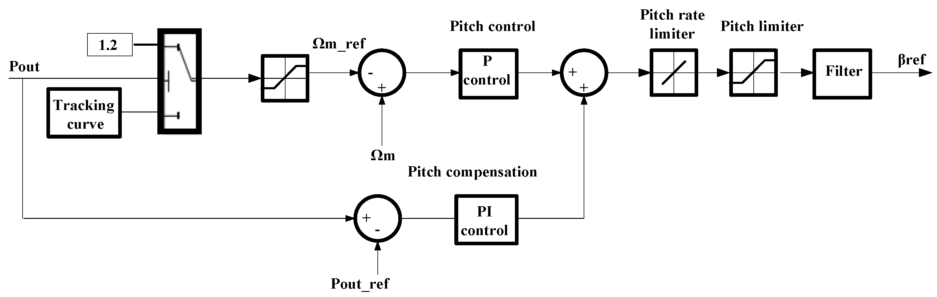
  • The combination of the control of rotor speed and output power using fuzzy tuned PI in power control, allowing the changeable tuning of PI parameters depending on system conditions;
  • Regulating the output power while maintaining the desired rotor speed and avoiding equipment overloads;
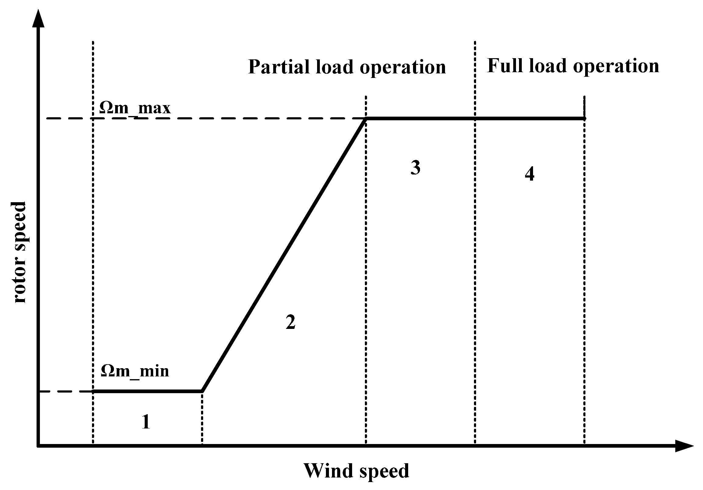
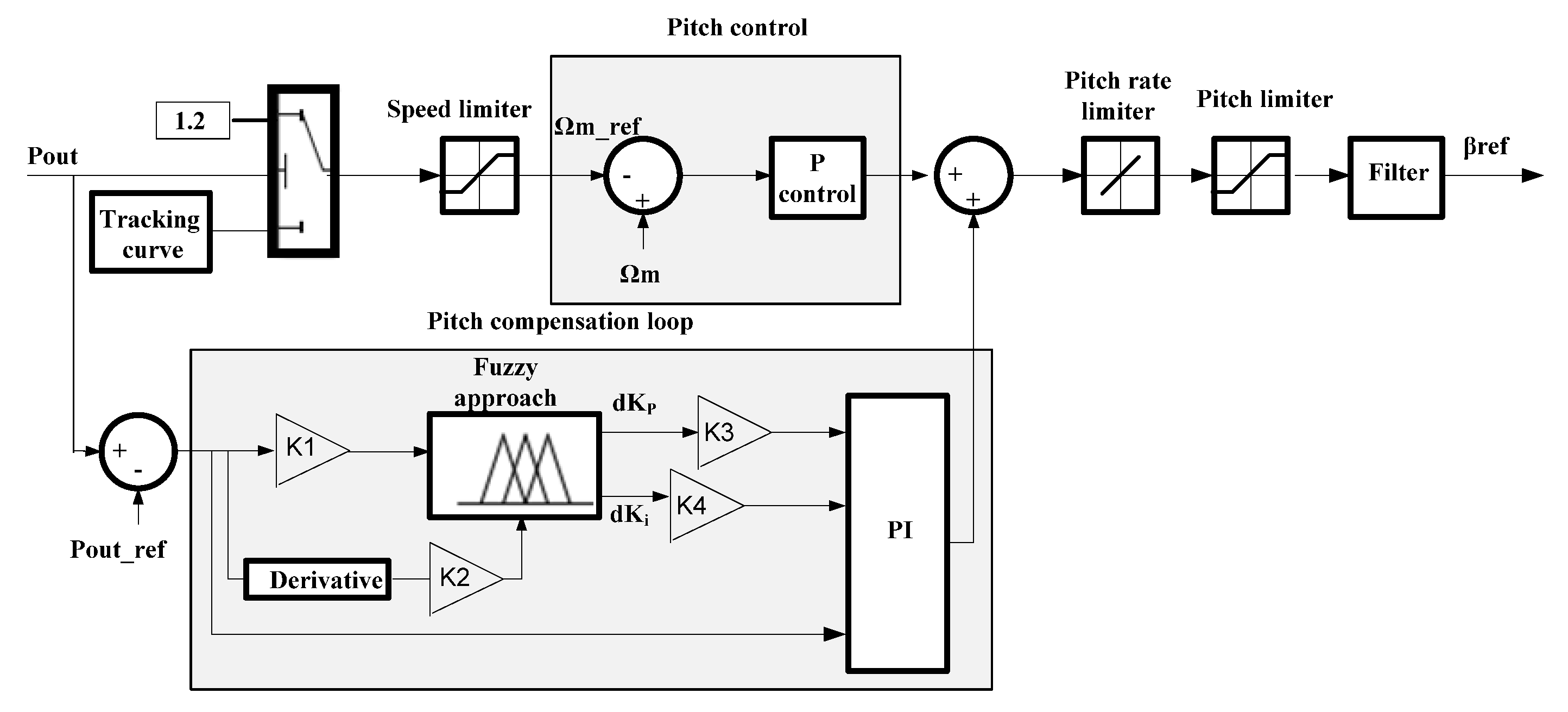
  • For power levels below a nominal value, the power is controlled to reduce the turbine speed according to the power–speed curve (tracking curve) illustrated in [31]. This is approximated by adjusting the reference speed.
The case study for the studied model is a large-scale wind farm consisting of six rows of DFIG based wind turbines with a total capacity of 120 MW in the Gulf El-Zayt region, Red Sea, Egypt [33]. The system’s validity is substantiated by studying different cases of wind speed variation: ramp, step, random, and extreme wind speed. The result is compared with conventional combined control; the comparison illustrates the effectiveness of the fuzzy PI system over that of conventional control. This paper is organized as follows: Section 2 describes how the wind turbine extracts power. The control of the pitch angle is illustrated in Section 3, and Section 4 shows a brief discussion about fuzzy control. Section 5 describes the methodology of pitch control used in the paper. In Section 6, the model’s configuration is illustrated, and discussion of the results verifies the methodology. Finally, a brief conclusion is presented.

2. Wind Turbine Aerodynamics

The wind turbine can extract power Pt from kinetic energy of the wind and is given by:
P t = 0.5 ρ π R 2 V v 3 C p ,
where ρ is the air density, R is the wind rotor radius, Vv is the wind speed, and Cp is the power coefficient, which is a function of tip speed ratio λ (TSR) and the blade pitch angle [34]. TSR is a function of the angular speed of the rotor Ωm and is given by:
λ = R Ω m / V v .
The mechanical drive train consists of blades that link to the hub and are then coupled to the slow shaft, which is connected to the gearbox, which transfers the rotational motion to the fast shaft, which drives the generator [34]. There are two techniques for the power control of wind turbines; stall, or passive, control and pitch control. The stall control is very simple as it works passively by changing the angle at which the wind strikes the blade, and when wind speed increases, it automatically increases. On the other hand, the aerodynamic design required is very complex and is also exposed to some challenges such as induced vibration and low efficiency at low wind speed [12]. The pitch control checks the rotor speed and the output electric power of the turbines. When the wind speed increases beyond a specified limit, the controller sends a signal to the blade mechanism to turn out of the wind, increasing the pitch angle to decrease the area of attack. The rate of change of the pitch angle is limited to about 10 deg/s [35]. The wind turbine can also control the power by mixing both types of control and this has many advantages: the ability to achieve smooth limited power without high power fluctuations and to compensate for variations in air density.
The control of wind turbines aims to extract the maximum energy and keep the turbines in safe operation while also decreasing the mechanical loads. This is performed by calculating the pitch angle and the generator torque references. DFIG is one of the most common electric techniques applied to wind turbines. DFIG with power converters can provide power control by means of a pitchable blade. DFIG has preferable features such as fewer power losses, flexible control of active and reactive power, and low converter cost. DFIG is constructed as illustrated in Figure 1, where the stator is connected directly to the grid and the rotor is connected via a bidirectional converter. The DFIG develops an electromagnetic torque Te that is a function of the stator flux φ and rotor current ir and is given by the following equation:
T e = 1.5 P ( ϕ d s i q r ϕ q s i d r ) L m / L s ,
where, Ls, Lm are stator and magnetizing inductance. P is the number of pole pairs. d and q subscripts refer to the d-q axis components in the synchronous frame [36].

3. Pitch Angle Control

The design of wind turbines is based on generating electrical energy as cheaply as possible. Therefore, wind turbines are designed so that they generate maximum power at a wind speed of around 15 m per second. For stronger winds, it is necessary to waste part of the excess energy of the wind to avoid damaging the wind turbine [35]. Therefore, all wind turbines are designed with a power controller. Pitch control is a sort of power control where a blade pitch mechanism changes the rotor blade’s angle. The strategy of wind turbine control consists of four operation zones [37] as illustrated in Figure 2. In the first region, the wind generator starts to run at cut-in wind speed with a minimum speed of operation. In the second region, the rotor speed is less than the maximum limit, so the pitch control does not operate until the third region, where the rotor speed reaches the maximum. The output power must be limited at the fourth region, where the wind turbine’s operation is at full load [35].
There are many control techniques of pitch angle adjustment that are applied to wind turbines. The pitch control loop simulated by MATLAB uses combined control loops, which are the traditional proportional controller, to regulate rotor speed along with traditional PI control compensation to regulate the rated power output of wind turbines; this is illustrated in Figure 3. The input to the first part is the error of the rotor speed that drives the proportional controller, and the input to the compensation part is the output power error that drives the PI controller. The output of two parts is added to extract the reference pitch angle (βref). The reference rotor speed is adjusted according to the power speed curve (tracking curve) for power levels below a nominal value. For high wind speeds, the reference rotor speed is limited to 1.2 p.u. [8,31,32].

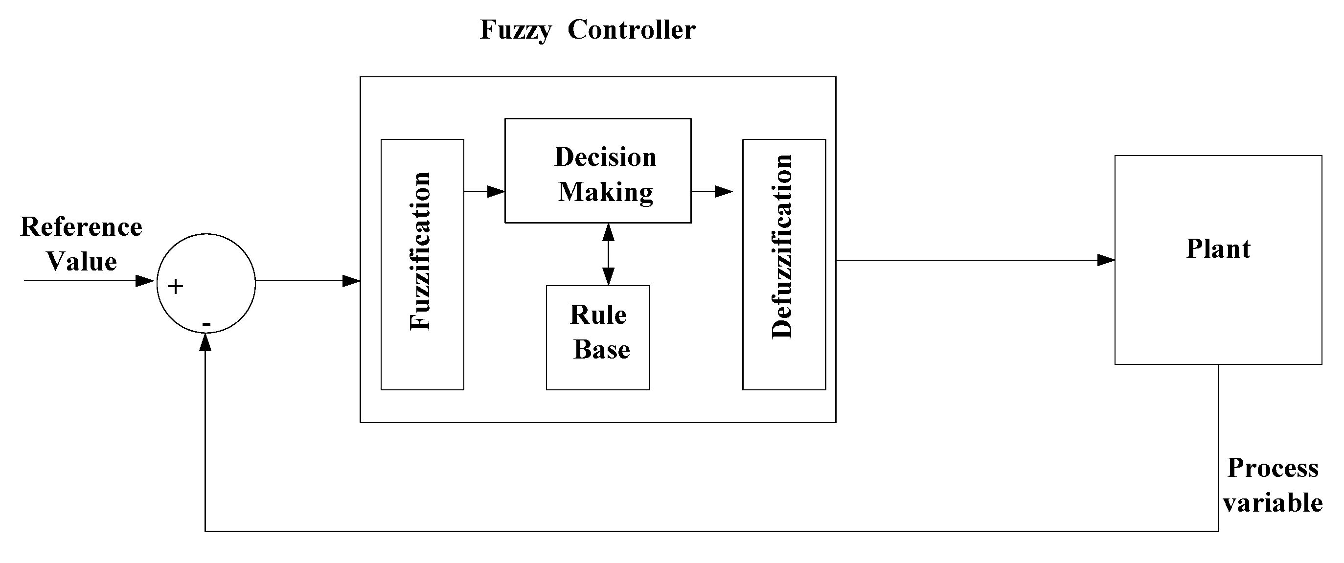
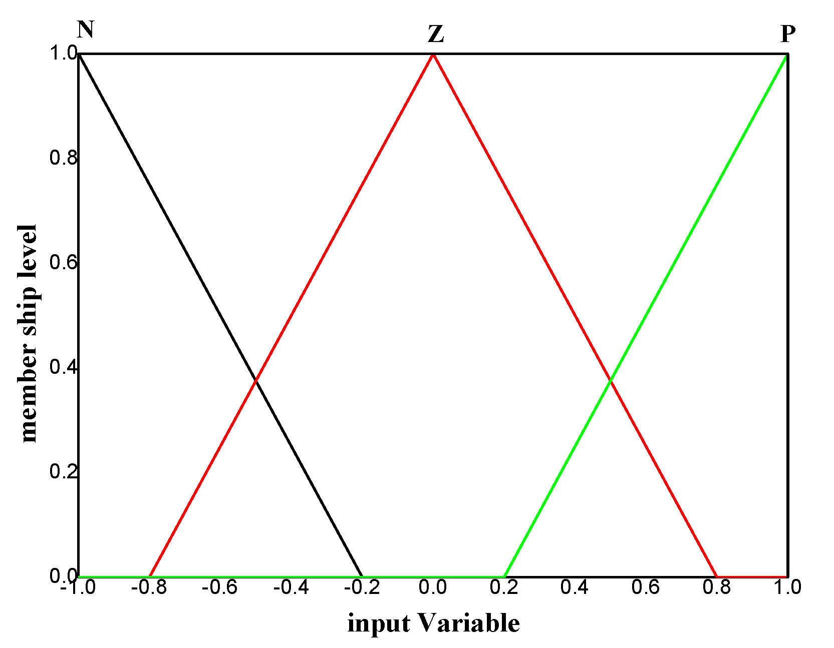
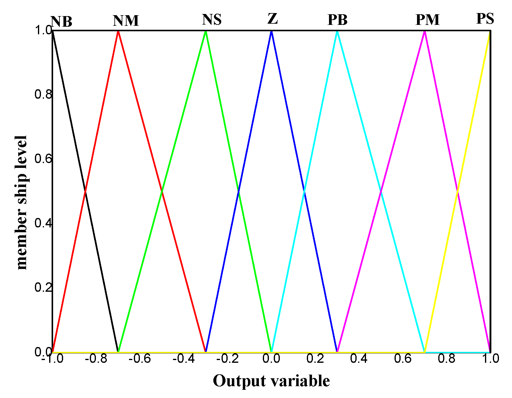
4. Fuzzy Logic Approach

In fuzzy logic approach, the element is expressed by membership degree unlike in the crisp logic approach, where the variable is expressed by two values, 1 or 0. The membership degree of the fuzzy element is provided by different types of membership functions, which convert the crispy input within a range between 0 and 1. The membership function can be trapezoidal, triangular, or Gaussian. For example, the triangular membership with start point α, end point γ, and mid-point β is expressed as follows [38,39]:
A = { 0 , x < α ( x α ) / ( β α ) , α x β ( γ x ) / ( γ β ) , β x γ 0 , x > γ } .
Fuzzy approach uses if–then rules to relate the input variables to the output variables, then the fuzzy output is converted to crispy values—this is named defuzzification. There are many methods of defuzzification such as bisector, centroid or (mean, largest, or smallest) value of maximum, and the most common one is the centroid. Figure 4 shows the fuzzy approach in a control system [38].

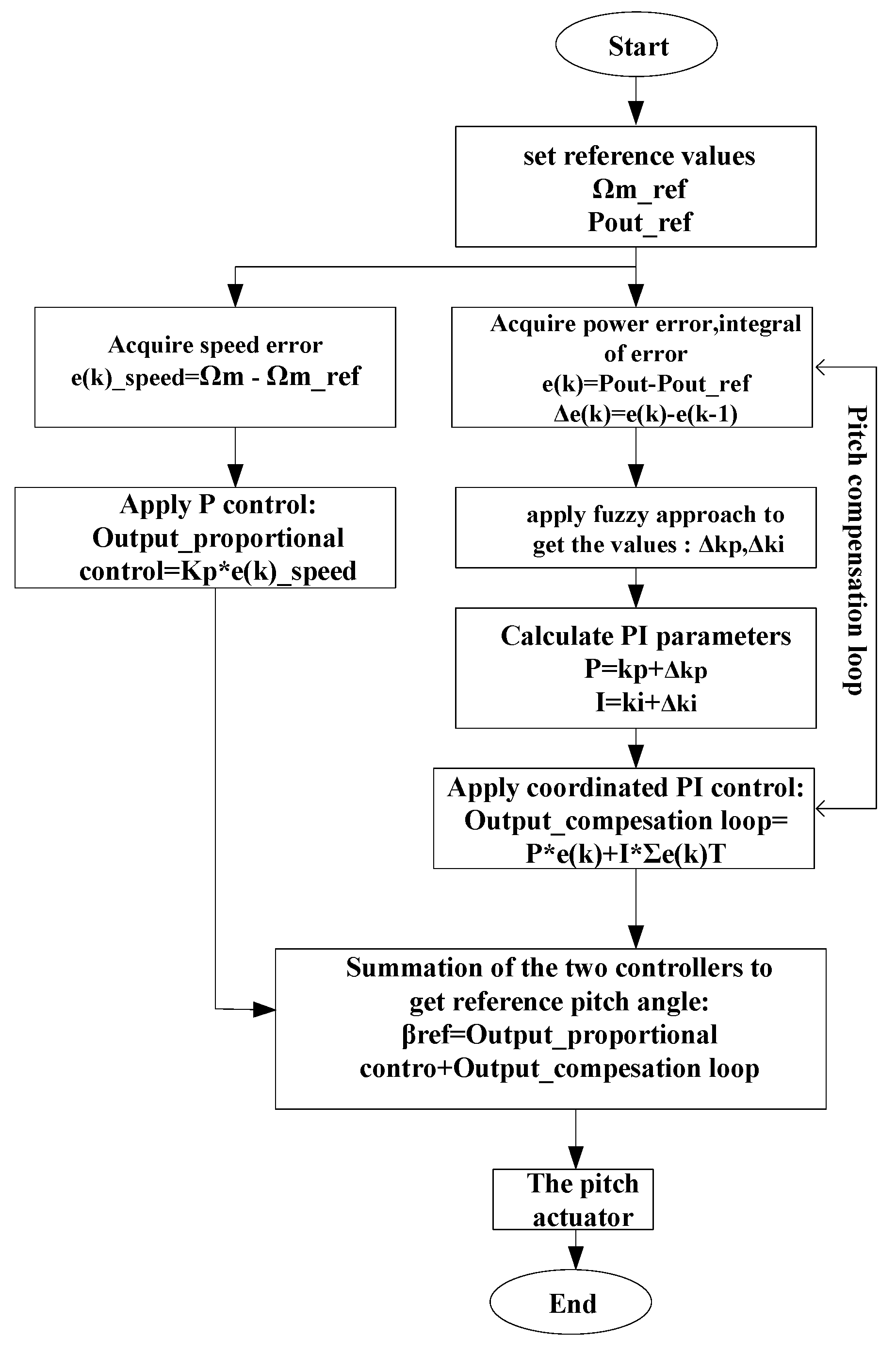
5. Designing and Applying Fuzzy PI in Pitch Angle Control

In this paper, a combination of the traditional P control and fuzzy adaptive PI is applied for pitch angle control in DFIG. The combined control regulates rotor speed and output power, which enables the avoidance of equipment overloads. The fuzzy adaptive PI is applied to pitch compensation instead of the traditional PI control, as shown in Figure 5. The fuzzy system is used in such a way to modify the parameters of the conventional controller.
The fuzzy inputs are the power error and the derivative of the error; the outputs are the amount of change of the PI constant (dkp, dki). Then the PI controller output is added to proportional pitch control to generate the reference pitch angle. In this paper, the fuzzy is double-input and double-output and uses the rule-based Mamdani type and the centroid defuzzification method. The amount of change of the PI constants is added to the main values of the PI parameter; whether it is to be increased or decreased depends on the error change, so that minimizing the error finally accelerates the stability of the system output. The specified rule base of fuzzy logic determines the change amount of PI parameters; the dkp rules are shown in Table 1. The rule base of the dki parameter is the same as in the dkp table. The fuzzy sets of the fuzzy input (the error and change of error) and the fuzzy output are shown in Figure 6 and Figure 7, respectively.
When the power error is negative, the reference signal is greater than the measured value. Therefore, the PI parameters should be set in a way that accelerates the measured power to decrease the error. This is achieved by increasing kp. In this case, if the derivative of the error is negative, extension of the failure is accelerated, and if the derivative of the error is positive, the extension of kp is slowed down to prevent the exceedance. The triangular fuzzy membership functions of the fuzzy inputs are displayed for the three linguistic variables of P, Z and N, and the fuzzy outputs are displayed for the seven linguistic variables of PB, PM, PS, Z, NS, NM and NB. Below are some of the fuzzy rules.
  • IF e is P and Δe is P THEN dkp is NB.
  • IF e is Z and Δe is P THEN dkp is Z.
  • IF e is N and Δe is N THEN dkp is PB.
The error and the change of the error of output active power, which are the inputs to the fuzzy, are calculated as follows [39,40]:
e ( k ) = P o u t P o u t r e f
Δ e ( k ) = e ( k ) e ( k _ p r e v i o u s ) T ,
where T > 0, is the sampling period. The fuzzy outputs give the amount of change of the PI parameters (P, I) and the output of the PI controller is given by the following equation [39]:
c o m p e n s a t i o n _ o u t p u t = P e ( k ) + T I n = 0 t e ( n ) .
The flow chart in Figure 8 illustrates the steps of fuzzy coordinated PI implementation in pitch angle control. Initially, the reference values of rotor speed and output power are set. The rotor speed is compared to its reference value (Ωm_ref) and the output power is compared with the nominal value of 1 p.u. The rotor speed error is regulated by the first control loop (proportional control). The output power error and its derivative are entered to the fuzzy approach in a compensation control loop. The fuzzy generates the change in the PI parameters and the PI control regulates the output power error. The summation of the two control outputs is the reference pitch angle.
The objective of the combined control is to regulate power production and maintain it in the specified limit while maintaining the desired rotor speed and avoiding equipment overloads with the implementation of fuzzy PI, which improves the performance of the control. Other previous work controls the output power or rotor speed to adjust the pitch angle. The authors of [41] adjust the reference pitch angle by controlling the output power with fuzzy PID. Reference [42] designs the pitch angle control based on fuzzy PID for small scale wind turbine systems. The fuzzy PID controller operates based on the error of the rotor speed. In [43], the reference pitch angle is adjusted by controlling the rotor speed with fuzzy PI control. The research in [44] uses an IPC control process, by obtaining the tilt moment and yaw moment at the hub center, so the output of the fuzzy PI controller obtains the tilt direction and yaw direction pitch angle. In [45], the authors propose a fuzzy predictive algorithm for the collective pitch control of large wind turbines; however, the fuzzy rules depend on wind speed as a linguistic variable. On the other hand, measurements of the wind speed are inaccurate with the high level of noise due to its variations across the blades’ swept area. The research in [32] applied control to the active power and rotor speed with traditional p control and fractional order PI control.

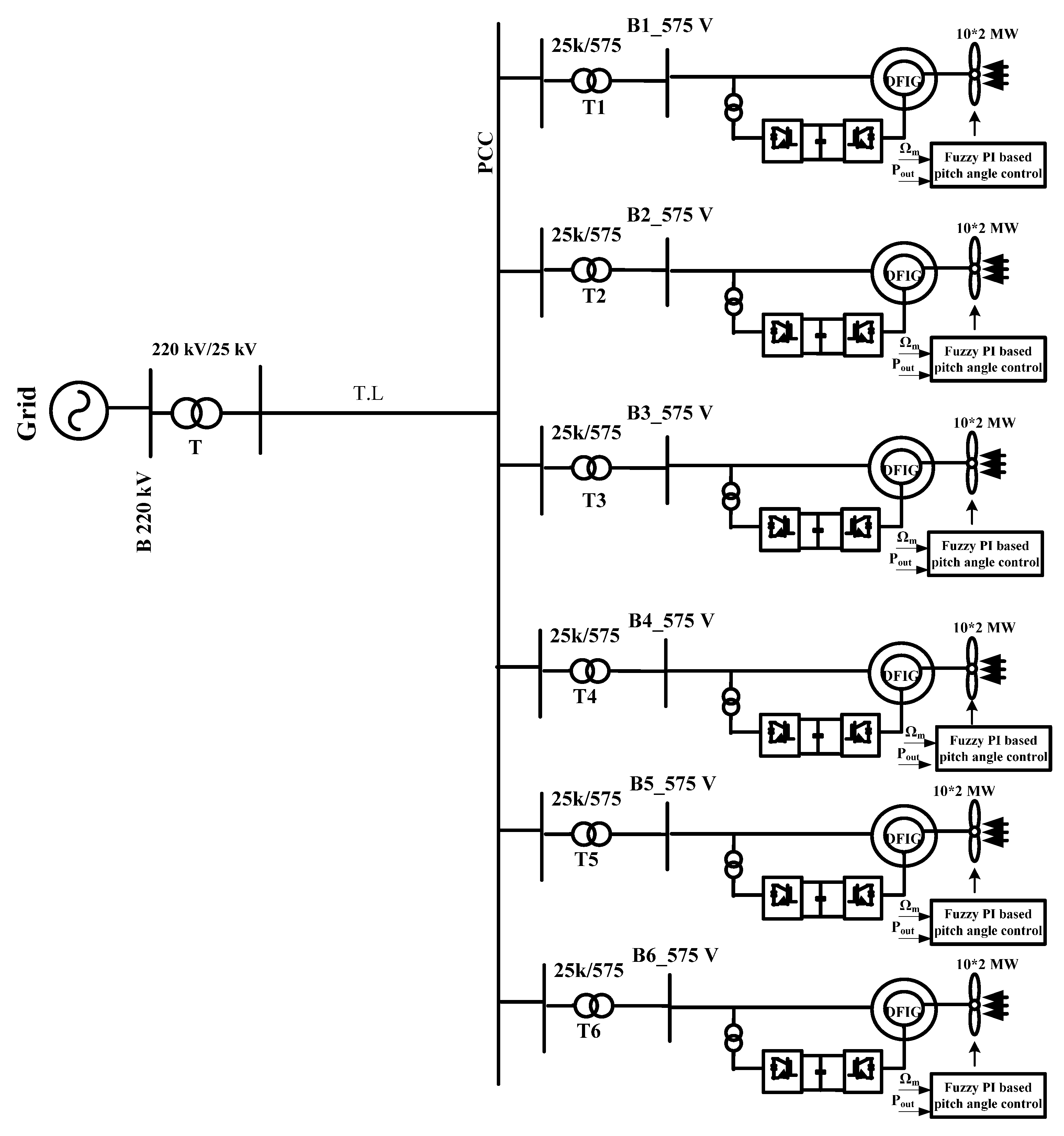
6. Model Configuration and Results Discussion

A large-scale wind farm with a total rated capacity of 120 MW in the Gulf El-Zayt region, Red Sea, Egypt, was simulated as a case study [33]. It consists of six rows of wind turbines operated with DFIG, where each row has ten turbines each with a capacity of 2 MW, and each turbine is controlled by the combined pitch angle control (proportional control and fuzzy PI control). The farm is connected to a 220 kV electrical grid and the output power is exported through a 25 kV transmission line that is 30 km long. Figure 9 shows the single line diagram of the studied wind farm.
The system simulation studied three different cases of wind speed with a performance comparison between fuzzy coordinated PI with corresponding conventional PI in the combined pitch angle control to validate the advantages of applying fuzzy coordinated PI in the pitch angle control compensation. The wind speed was applied, with different functions, to the system model, such as ramp, step, random, and extreme wind speed. In the simulated model, all rows were subjected to the same condition (same wind speed) as the delay time was neglected between rows for simplicity.

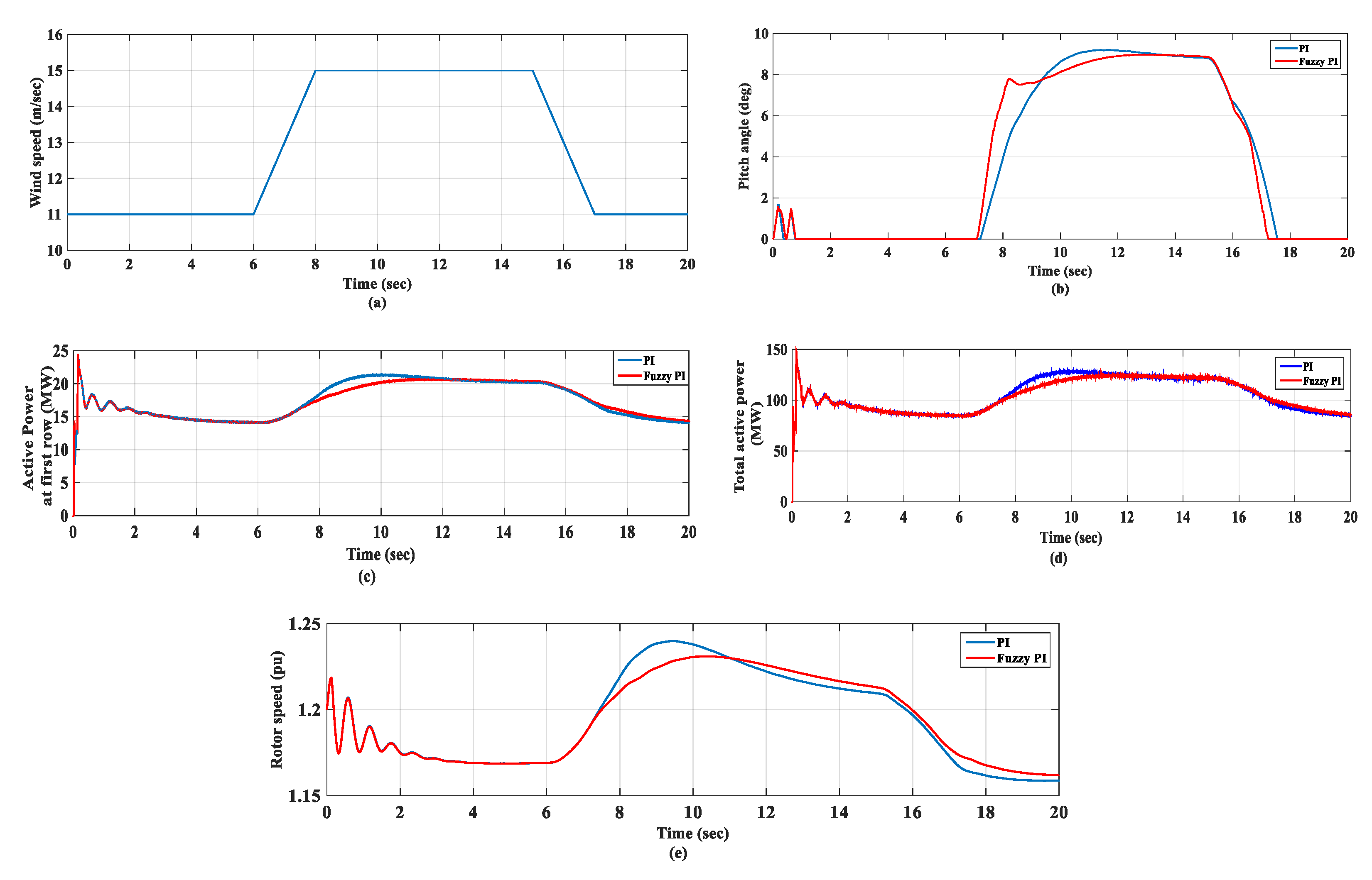
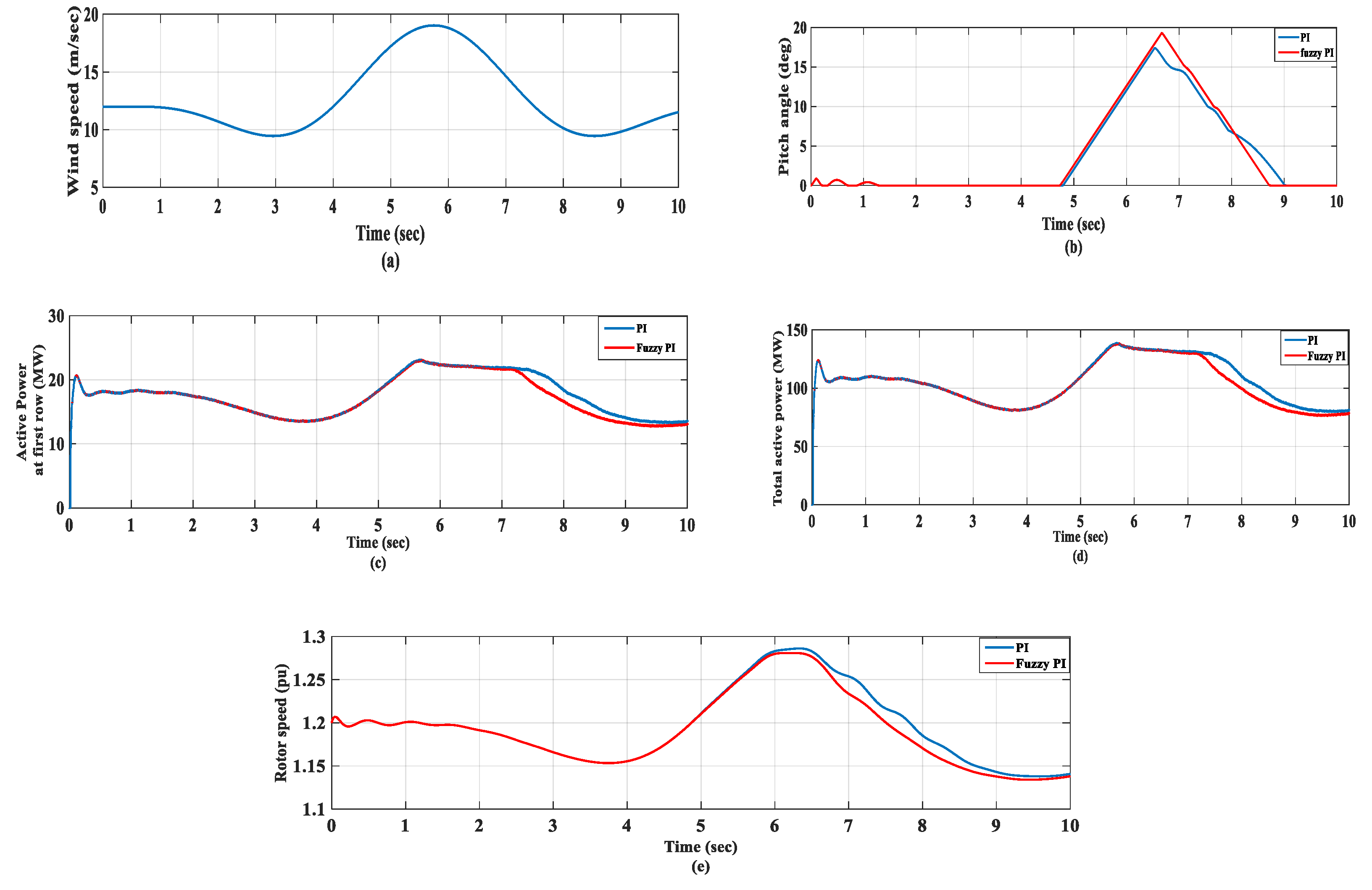
6.1. Ramp Wind Speed

In this case, wind speed was applied to the system as a ramp function as shown in Figure 10a. Initially, the wind speed was 11 m/s then changed at 6 s to 15 m/s for a short duration (2 s), then returned to the previous value starting at 15 s for the same duration to get to the final value of 17 s. The response of the system was studied on the pitch angle, active power at the first row, total active power, and the rotor speed, as shown in Figure 10b–e. Until 6 s, the wind speed was at 11 m/s, corresponding to the nominal rotor speed so the pitch angle was zero and the corresponding total power was at 85 MW. When the wind speed increased from 11 to 15 m/s, the pitch angle, active power at the first row and total active power had overshoots of 9.18 deg, 21.3 MW and 128 MW, respectively, with PI, but with fuzzy PI, there was no overshoot and it smoothly achieved a steady-state value of 8.8 deg, 20 MW and 120 MW, respectively. The rotor speed had overshoot of 1.24 p.u. with PI, and 1.23 p.u. with fuzzy PI. When the wind speed changed from 15 to 11 m/s, the pitch angle returned to zero at 17.6 s with PI but took less time with fuzzy PI, as it reached zero at 17.2 s and the active power and rotor speed achieved the final value faster with fuzzy PI compared to traditional PI.

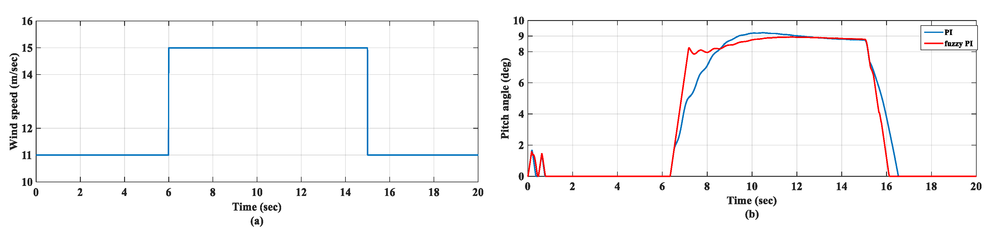
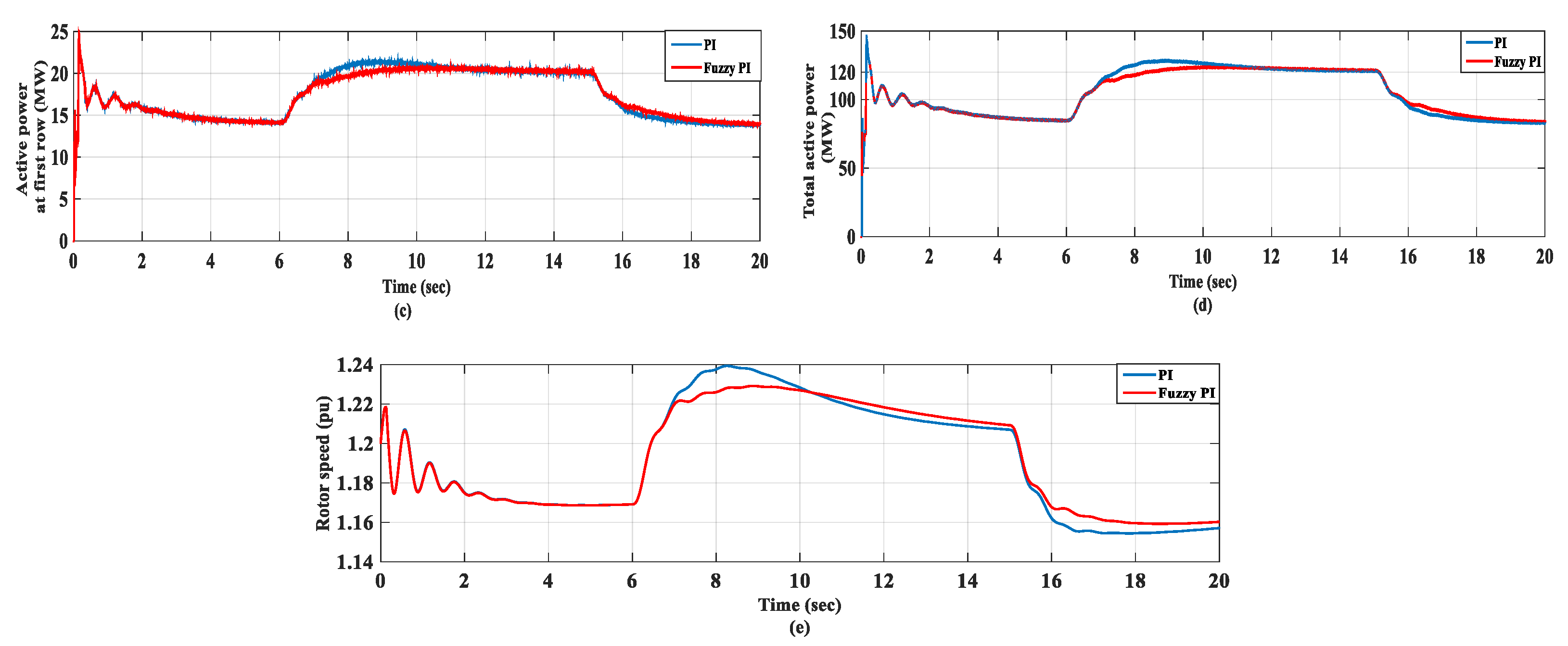
6.2. Step Wind Speed

In this case, wind speed was applied to the system as a step function as shown in Figure 11a. Initially, the wind speed was 11 m/s then changed at 6 s to 15 m/s, then returned to its previous value at 15 s. The pitch angle, active power at the first row, total active power, and the rotor speed response were studied on the system as shown in Figure 11b–e, respectively. In the beginning, the wind speed was at 11 ms so the pitch angle was zero and the corresponding total power was at 85 MW. The rotor speed was also at 1.17 p.u. When the wind speed increased instantaneously to 15 m/s, the pitch angle, active power at the first row, and the total active power had overshoots of 9.21 deg, 21.4 MW and 128.2 MW, respectively, with PI, but with fuzzy PI, there was no overshoot and it smoothly reached a steady-state value of 8.8 deg, 20 MW and 120 MW, respectively. The rotor speed had overshoot of 1.24 p.u. with PI, and 1.23 p.u. with fuzzy PI. When the wind speed returned instantaneously to 11 m/s, the pitch angle returned to zero at 16.54 s with PI but took less time with fuzzy PI as it reached zero at 16.12 s and the active power and rotor speed achieved the final value faster with fuzzy PI compared to traditional PI.

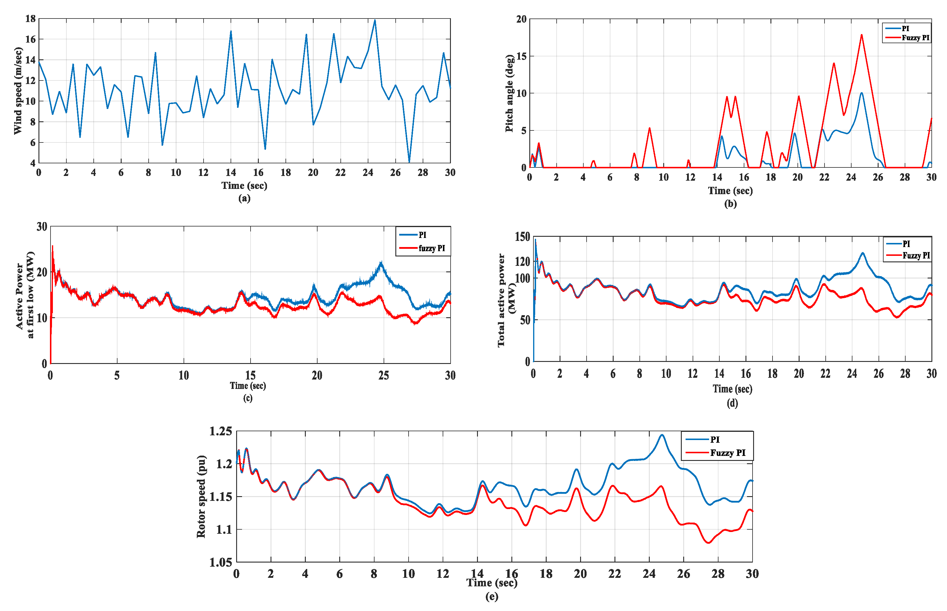
6.3. Random Wind Speed

In this case, wind speed was changed as a random function as shown in Figure 12a. The response of the pitch angle, active power at the first row, total active power, and rotor speed is shown in Figure 12b–e, respectively. The response of the pitch angle was faster with fuzzy PI than with traditional PI as, for example, at 8.5 s the wind speed reached 15 m/s, which required changing of the pitch angle, and the traditional PI could not keep up this change while keeping the pitch angle at zero. However, fuzzy PI made the pitch angle increase. With traditional PI, the active power was more than its rated value at 25 s during random speed and the rotor speed also changed to a high value of 1.24 p.u. which did not happen with fuzzy PI.

6.4. Extreme Wind Speed

In this case, wind speed was changed as an extreme wind function, from 12 to 9.4 ms then increased to 19 m/s and decreased again to 9.4 m/s as shown in Figure 13a. The response of the pitch angle, active power at the first row, total active power, and rotor speed is shown in Figure 13b–e, respectively. The response of the pitch angle was faster with fuzzy PI than with traditional PI, as when the wind speed increased to 19 ms, the pitch angle began to increase at 4.72 s with fuzzy PI but began to increase at 4.8 s with PI. When the wind speed decreased again to 9.4 ms, the pitch angle also decreased and reached zero at 8.7 s with fuzzy PI but reached this value at 9 s with PI. Active power and the rotor speed response were faster with fuzzy PI than with traditional PI, which was illustrated more clearly when the wind speed decreased from 19 to 9.4 ms.

7. Conclusions

The main objective of this paper was to develop and apply a fuzzy proportional integral control scheme combined with traditional proportional control to the dynamic behavior of pitch angle-regulated wind turbine blades. Depending on the operating point of the system, the fuzzy approach determines the best values for PI parameters and the output of a pitch compensation loop added to the proportional pitch control to generate the reference pitch angle. The simulation is carried out on a case study of a large-scale wind farm in the Gulf El-Zayt region, Red Sea, Egypt, with a total rated capacity of 120 MW connected to a 220 kV electrical grid. The validity of the fuzzy system is approved by studying different cases of wind speed. The utilization of fuzzy adaptive PI control is compared with conventional PI; the results illustrate the performance of the affected parameters: active power, pitch angle and rotor speed. The ramp wind speed varies from 11–15–11 m/s, and the pitch angle and total active power have overshoots of 9.18 deg and 128 MW, respectively, with PI, but with fuzzy PI, there is no overshoot and it smoothly reaches a steady-state value of 8.8 deg and 120 MW, respectively. Rotor speed has an overshoot of 1.24 p.u. with PI, and 1.23 p.u. with fuzzy PI. The step wind speed varies from 11–15–11 m/s, and the pitch angle and total active power have overshoots of 9.21 deg and 128.2 MW, respectively, with PI, but with fuzzy PI, there is no overshoot and it smoothly reaches a steady-state value of 8.8 deg and 120 MW, respectively. Rotor speed has an overshoot of 1.24 p.u. with PI, and 1.23 p.u. with fuzzy PI. When the wind speed changes as a random function and as an extreme wind speed, the responses of the parameters are faster with fuzzy PI than with traditional PI. The comparison illustrates the effectiveness of the fuzzy PI system over conventional combined control. Despite the advantages of the fuzzy logic approach, there are some problems with finding suitable membership values and requiring fine tuning before operation. For future work, a neuro-fuzzy integrated approach is suggested, to apply to the system to overcome these demerits.

Author Contributions

Conceptualization, I.H.; Investigation, I.H. and O.N.; Methodology, I.H.; Software, I.H. and M.M.M.Y.; Supervision, I.H. and O.N.; Validation, S.A. and M.M.M.Y.; Visualization, S.A.; Writing—original draft, M.M.M.Y.; Writing—review & editing, S.A., I.H. and O.N. All authors have read and agreed to the published version of the manuscript.

Funding

The authors extend their appreciation to the Deputyship for Research & innovation, Ministry of Education in Saudi Arabia for funding this research work through the project number: MOE-BU-8-2020.

Data Availability Statement

Not applicable.

Conflicts of Interest

The authors declare no conflict of interest.

References

  1. Whittlesey, R. Vertical axis wind turbines: Farm and turbine design. In Wind Energy Engineering; Elsevier: Amsterdam, The Netherlands, 2017; pp. 185–202. [Google Scholar]
  2. Giaourakis, D.G.; Safacas, A.N. Effect of short-circuit faults in the back-to-back power electronic converter and rotor terminals on the operational behavior of the doubly-fed induction generator wind energy conversion system. Machines 2015, 3, 2–26. [Google Scholar] [CrossRef] [Green Version]
  3. Abdelrahem, M.; Hackl, C.M.; Kennel, R. Limited-Position Set Model-Reference Adaptive Observer for Control of DFIGs without Mechanical Sensors. Machines 2020, 8, 72. [Google Scholar] [CrossRef]
  4. Habibi, H.; Howard, I.; Simani, S. Reliability improvement of wind turbine power generation using model-based fault detection and fault tolerant control: A review. Renew. Energy 2019, 135, 877–896. [Google Scholar] [CrossRef]
  5. Lio, W.H.; Jones, B.L.; Rossiter, J.A. Estimation and control of wind turbine tower vibrations based on individual blade-pitch strategies. IEEE Trans. Control Syst. Technol. 2018, 27, 1820–1828. [Google Scholar] [CrossRef] [Green Version]
  6. Apata, O.; Oyedokun, D. An Overview of Control Techniques for Wind Turbine Systems. Sci. Afr. 2020, 10, e00566. [Google Scholar] [CrossRef]
  7. Yang, Q.; Jiao, X.; Luo, Q.; Chen, Q.; Sun, Y. L1 adaptive pitch angle controller of wind energy conversion systems. ISA Trans. 2020, 103, 28–36. [Google Scholar] [CrossRef]
  8. Dida, A.; Merahi, F.; Mekhilef, S. New grid synchronization and power control scheme of doubly-fed induction generator based wind turbine system using fuzzy logic control. Comput. Electr. Eng. 2020, 84, 106647. [Google Scholar] [CrossRef]
  9. De Carvalho, W.C.; Bataglioli, R.P.; Fernandes, R.A.; Coury, D.V. Fuzzy-based approach for power smoothing of a full-converter wind turbine generator using a supercapacitor energy storage. Electr. Power Syst. Res. 2020, 184, 106287. [Google Scholar] [CrossRef]
  10. Samet, H.; Ketabipoor, S.; Vafamand, N. EKF-based TS fuzzy prediction for eliminating the extremely fast reactive power variations in Manjil wind farm. Electr. Power Syst. Res. 2021, 199, 107422. [Google Scholar] [CrossRef]
  11. Fekry, H.M.; Eldesouky, A.A.; Kassem, A.M.; Abdelaziz, A.Y. Power Management Strategy Based on Adaptive Neuro Fuzzy Inference System for AC Microgrid. IEEE Access 2020, 8, 192087–192100. [Google Scholar] [CrossRef]
  12. Prakash, A.O.; Banu, R.N.; Devaraj, D. Maximum Energy Extraction of a Wind Farm Using Pitch Angle Control. In Proceedings of the 2019 IEEE International Conference on Intelligent Techniques in Control, Optimization and Signal Processing (INCOS), Tamilnadu, India, 11–13 April 2019; pp. 1–7. [Google Scholar]
  13. Li, P.; Song, Y.D.; Li, D.Y.; Cai, W.C.; Zhang, K. Control and monitoring for grid-friendly wind turbines: Research overview and suggested approach. IEEE Trans. Power Electron. 2014, 30, 1979–1986. [Google Scholar] [CrossRef]
  14. Iqbal, A.; Ying, D.; Saleem, A.; Hayat, M.A.; Mehmood, K. Efficacious pitch angle control of variable-speed wind turbine using fuzzy based predictive controller. Energy Rep. 2020, 6, 423–427. [Google Scholar] [CrossRef]
  15. Bououden, S.; Chadli, M.; Filali, S.; El Hajjaji, A. Fuzzy model based multivariable predictive control of a variable speed wind turbine: LMI approach. Renew. Energy 2012, 37, 434–439. [Google Scholar] [CrossRef]
  16. Poultangari, I.; Shahnazi, R.; Sheikhan, M. RBF neural network based PI pitch controller for a class of 5-MW wind turbines using particle swarm optimization algorithm. ISA Trans. 2012, 51, 641–648. [Google Scholar] [CrossRef] [PubMed]
  17. Jia, C.; Wang, L.; Meng, E.; Chen, L.; Liu, Y.; Jia, W.; Bao, Y.; Liu, Z. Combining LIDAR and LADRC for intelligent pitch control of wind turbines. Renew. Energy 2021, 169, 1091–1105. [Google Scholar] [CrossRef]
  18. Frost, S.A.; Balas, M.J.; Wright, A.D. Direct adaptive control of a utility-scale wind turbine for speed regulation. Int. J. Robust Nonlinear Control IFAC-Affil. J. 2009, 19, 59–71. [Google Scholar] [CrossRef]
  19. Badihi, H.; Zhang, Y.; Pillay, P.; Rakheja, S. Fault-Tolerant Individual Pitch Control for Load Mitigation in Wind Turbines with Actuator Faults. IEEE Trans. Ind. Electron. 2020, 68, 532–543. [Google Scholar] [CrossRef]
  20. Sarkar, M.R.; Julai, S.; Tong, C.W.; Uddin, M.; Romlie, M.; Shafiullah, G. Hybrid pitch angle controller approaches for stable wind turbine power under variable wind speed. Energies 2020, 13, 3622. [Google Scholar] [CrossRef]
  21. Bashetty, S.; Guillamon, J.I.; Mutnuri, S.S.; Ozcelik, S. Design of a robust adaptive controller for the pitch and torque control of wind turbines. Energies 2020, 13, 1195. [Google Scholar] [CrossRef] [Green Version]
  22. Rashid, A.; Ying, D. Fuzzy Inference Based Approach for Pitch Angle Control of Variable Speed Variable Pitch Wind Turbine. In Proceedings of the 2020 Asia Energy and Electrical Engineering Symposium (AEEES), Chengdu, China, 28–31 May 2020; pp. 1051–1056. [Google Scholar]
  23. Ren, H.; Hou, B.; Zhou, G.; Shen, L.; Wei, C.; Li, Q. Variable pitch active disturbance rejection control of wind turbines based on BP neural network PID. IEEE Access 2020, 8, 71782–71797. [Google Scholar] [CrossRef]
  24. Tang, X.; Yin, M.; Shen, C.; Xu, Y.; Dong, Z.Y.; Zou, Y. Active power control of wind turbine generators via coordinated rotor speed and pitch angle regulation. IEEE Trans. Sustain. Energy 2018, 10, 822–832. [Google Scholar] [CrossRef]
  25. Yin, X.; Zhao, X. Composite hierarchical pitch angle control for a tidal turbine based on the uncertainty and disturbance estimator. IEEE Trans. Ind. Electron. 2019, 67, 329–339. [Google Scholar] [CrossRef]
  26. De, T.; Rashid, A.; Ying, D.; Sheng, L.H. Pitch Angle Control of Modern Variable Speed Variable Pitch Wind Turbine Based on Linear Active Disturbance Rejection Control Approach. In Proceedings of the 2020 IEEE/IAS Industrial and Commercial Power System Asia (I&CPS Asia), Chengdu, China, 13–16 July 2020; pp. 1382–1387. [Google Scholar]
  27. Datta, U.; Shi, J.; Kalam, A. Primary frequency control of a microgrid with integrated dynamic sectional droop and fuzzy based pitch angle control. Int. J. Electr. Power Energy Syst. 2019, 111, 248–259. [Google Scholar] [CrossRef]
  28. Prasad, R.; Padhy, N.P. Synergistic frequency regulation control mechanism for DFIG wind turbines with optimal pitch dynamics. IEEE Trans. Power Syst. 2020, 35, 3181–3191. [Google Scholar] [CrossRef]
  29. Rezaeiha, A.; Kalkman, I.; Blocken, B. Effect of pitch angle on power performance and aerodynamics of a vertical axis wind turbine. Appl. Energy 2017, 197, 132–150. [Google Scholar] [CrossRef] [Green Version]
  30. Chen, C.C.; Kuo, C.H. Effects of pitch angle and blade camber on flow characteristics and performance of small-size Darrieus VAWT. J. Vis. 2013, 16, 65–74. [Google Scholar] [CrossRef]
  31. Miller, N.W.; Sanchez-Gasca, J.J.; Price, W.W.; Delmerico, R.W. Dynamic modeling of GE 1.5 and 3.6 MW wind turbine-generators for stability simulations. In Proceedings of the 2003 IEEE Power Engineering Society General Meeting (IEEE Cat. No. 03CH37491), Toronto, ON, Canada, 13–17 July 2003; pp. 1977–1983. [Google Scholar]
  32. Mahvash, H.; Taher, S.A.; Rahimi, M.; Shahidehpour, M. Enhancement of DFIG performance at high wind speed using fractional order PI controller in pitch compensation loop. Int. J. Electr. Power Energy Syst. 2019, 104, 259–268. [Google Scholar] [CrossRef]
  33. Noureldeen, O.; Rashad, A. Modeling and investigation of Gulf El-Zayt wind farm for stability studying during extreme gust wind occurrence. Ain Shams Eng. J. 2014, 5, 137–148. [Google Scholar] [CrossRef] [Green Version]
  34. Pathak, D.; Gaur, P. A fractional order fuzzy-proportional-integral-derivative based pitch angle controller for a direct-drive wind energy system. Comput. Electr. Eng. 2019, 78, 420–436. [Google Scholar] [CrossRef]
  35. Abad, G.; Lopez, J.; Rodriguez, M.; Marroyo, L.; Iwanski, G. Doubly Fed Induction Machine: Modeling and Control for Wind Energy Generation; John Wiley & Sons: Hoboken, NJ, USA, 2011; Volume 85. [Google Scholar]
  36. Smajo, J.; Vukadinovic, D. Electromagnetic torque analysis of a DFIG for wind turbines. WSEAS Trans. Syst. 2008, 7, 479–488. [Google Scholar]
  37. Tiwari, R.; Babu, N.R. Recent developments of control strategies for wind energy conversion system. Renew. Sustain. Energy Rev. 2016, 66, 268–285. [Google Scholar] [CrossRef]
  38. Kose, U. Fundamentals of fuzzy logic with an easy-to-use, interactive fuzzy control application. Int. J. Mod. Eng. Res. 2012, 2, 1198–1203. [Google Scholar]
  39. Kanagaraj, N.; Sivashanmugam, P.; Paramasivam, S. Fuzzy coordinated PI controller: Application to the real-time pressure control process. Adv. Fuzzy Syst. 2008, 2008, 691808. [Google Scholar] [CrossRef] [Green Version]
  40. Amarendra Reddy, B.; Ram Charan, K.; Kranti Kiran, A.; Ramalingeswara Prasad, K. Control of Non-Linear Systems Using Parallel Structure of Fuzzy PI+PD Controller. Int. J. Eng. Sci. Technol. 2010, 2, 3422–3433. [Google Scholar]
  41. Civelek, Z.; Lüy, M.; Çam, E.; Barışçı, N. Control of pitch angle of wind turbine by fuzzy PID controller. Intell. Autom. Soft Comput. 2016, 22, 463–471. [Google Scholar] [CrossRef]
  42. Ngo, Q.V.; Chai, Y.; Nguyen, T.T. The fuzzy-PID based-pitch angle controller for small-scale wind turbine. Int. J. Power Electron. Drive Syst. 2020, 11, 135. [Google Scholar] [CrossRef] [Green Version]
  43. Badihi, H.; Zhang, Y.; Hong, H. Fuzzy gain-scheduled active fault-tolerant control of a wind turbine. J. Frankl. Inst. 2014, 351, 3677–3706. [Google Scholar] [CrossRef]
  44. Pan, T.; Ma, Z. Wind turbine individual pitch control for load reduction based on fuzzy controller design. Proc. Inst. Mech. Eng. Part I J. Syst. Control Eng. 2013, 227, 320–328. [Google Scholar] [CrossRef]
  45. Lasheen, A.; Elshafei, A.L. Wind-turbine collective-pitch control via a fuzzy predictive algorithm. Renew. Energy 2016, 87, 298–306. [Google Scholar] [CrossRef]
Figure 1. DFIG configuration.
Machines 09 00135 g001
Figure 2. Wind turbine operation zones.
Machines 09 00135 g002
Figure 3. The traditional pitch angle control.
Machines 09 00135 g003
Figure 4. Fuzzy approach system.
Machines 09 00135 g004
Figure 5. Pitch angle control with fuzzy adaptive PI.
Machines 09 00135 g005
Figure 6. Fuzzy sets of the inputs.
Machines 09 00135 g006
Figure 7. Fuzzy sets of the outputs.
Machines 09 00135 g007
Figure 8. Flow chart of the proposed control.
Machines 09 00135 g008
Figure 9. Large-scale wind farm model configuration.
Machines 09 00135 g009
Figure 10. System response during ramp wind speed: (a) wind speed, (b) pitch angle, (c) active power of first row, (d) total active power, (e) rotor speed.
Machines 09 00135 g010
Figure 11. System response during step wind speed: (a) wind speed, (b) pitch angle, (c) active power of first row, (d) total active power, (e) rotor speed.
Machines 09 00135 g011aMachines 09 00135 g011b
Figure 12. System response during random wind speed: (a) wind speed, (b) pitch angle, (c) active power of first row, (d) total active power, (e) rotor speed.
Machines 09 00135 g012
Figure 13. System response during extreme wind speed: (a) wind speed, (b) pitch angle, (c) active power of first row, (d) total active power, (e) rotor speed.
Machines 09 00135 g013
Table 1. Fuzzy PI Rule Table.
dkpDerivative of Error
PZN
ErrorPNBNMNS
ZZZZ
NPSPMPB
Publisher’s Note: MDPI stays neutral with regard to jurisdictional claims in published maps and institutional affiliations.

