
Passive Gravity Balancing with a Self-Regulating Mechanism for Variable Payload


1
Department of Engineering and Mathematics, Sheffield Hallam University, Sheffield S1 1WB, UK
2
Department of Management and Engineering, University of Padova, 36100 Vicenza, Italy
3
Department of Industrial Engineering, University of Padova, 35131 Padova, Italy
*
Author to whom correspondence should be addressed.
Machines 2021, 9(8), 145; https://0-doi-org.brum.beds.ac.uk/10.3390/machines9080145
Submission received: 21 May 2021
/
Revised: 22 July 2021
/
Accepted: 27 July 2021
/
Published: 29 July 2021
(This article belongs to the Section Machine Design and Theory)
Abstract
:Gravity balancing techniques allow for the reduction of energy consumptions in robotic systems. With the appropriate arrangements, often including springs, the overall potential energy of a manipulator can be made configuration-independent, achieving an indifferent equilibrium for any position. On the other hand, such arrangements lose their effectiveness when some of the system parameters change, including the mass. This paper proposes a method to accommodate different payloads for a mechanism with a single degree-of-freedom (DOF). By means of an auxiliary mechanism including a slider, pulleys and a counterweight, the attachment point of a spring is automatically regulated so as to maintain the system in indifferent equilibrium regardless of the position, even when the overall mass of the system varies. Practical implications for the design of the mechanism are also discussed. Simulation results confirm the effectiveness of the proposed approach.
1. Introduction
Constant force mechanisms exert forces with predetermined magnitude and direction, regardless of the mechanism configuration [1,2]. A common application of such systems in robotics is passive gravity balancing for manipulators. With no gravity-related burden on the actuators, these only need to compensate for inertial effects, resulting in reduced energy consumptions and a smaller actuator size (hence less weight and cost).
Passive gravity balancing is widely used in plenty of fields, including industry [3], medicine [4] and even everyday objects such as Anglepoise lamps [5,6]. Many literature contributions describe clever designs to achieve passive gravity balancing using counterweights [7], cams and springs [8,9,10,11,12]. In most spring-based designs, springs are assumed to have zero free length, i.e., to exert a force proportional to their length, rather than to the displacement with respect to a neutral position. While zero-free length springs do not physically exist, there are interesting solutions to mimic such a behavior with real springs [13,14,15,16]. Another practical aspect of gravity balancing is the need for auxiliary links. Such links are normally used to build parallelograms required to effectively anchor some springs, especially in serial manipulators [17]. Ref. [18] shows how to achieve static balancing without auxiliary links if the manipulator has a limited number of degrees of freedom. Interestingly, Ref. [19] proposes a generic solution avoiding auxiliary links, which, however, might be difficult to implement and might reduce the workspace of the manipulator.
The vast majority of the existing solutions assume that the weight of the system is fixed. Once the gravity balancing system is designed, it will keep the system in indifferent (neutral) equilibrium indefinitely. But in practice, the load might change, e.g., due to different payloads applied to the system during its operation. In that case, the system would no longer be in indifferent equilibrium. In principle, for a single Degree of Freedom (DOF) mechanism, it is sufficient to move one of the attachment points of the spring by a certain amount. However, this requires some calculations and manual intervention on the spring, which is practically inconvenient. Moreover, depending on the application, the forces applied by the spring might be significant. Ref. [20] suggests changing the stiffness of the spring, not by physically changing the spring, but through the idea of a virtual spring, practically obtained by two real springs and a pantograph mechanism. Ref. [21] proposes the use of a movable counterweight. Ref. [22] suggests installing two orthogonal springs and modifying their position. In [23], a self-regulating system is proposed, which requires moving the pivot of the link, which is also required by [24]. In recent works, the usage of gear springs modules has been investigated for the balancing against the gravity of planar articulated robotic arms [25] and of delta parallel robots [26]. In [27], non-linear spring configurations have been employed for the gravity compensation of robotic manipulators. In [28], a system combining a spring and a counterweight is employed. Ref. [29] proposes an analysis that explicitly divides parameters in payload-dependent and payload independent. Interestingly, Ref. [30] proposes a self-regulator mechanism for a 1-DOF link that does not require manual locking/releasing interventions. However, it requires changing the kinematics of the system, provoking a significant decrease in terms of workspace.
This paper presents a self-regulating mechanism for a 1-DOF link that allows for a change in the configuration of the system in order to accommodate different payloads, without the need of recalculating relevant parameters of the balancing system and then amending it accordingly. Practically, the mechanism is able to vary the position of one of the spring anchor points, exactly as required to balance the system with the new payload, without additional springs or manual intervention on the existing spring. The key features of the proposed approach, compared to similar works in the literature, are that the kinematics of the system is not affected, nor is the workspace of the system, and the pivot point of the link is not required to move.
The remainder of the paper is structured as follows. Section 2 presents the main principles and an analysis of the internal forces of a balanced single DOF link. Section 3 describes the proposed self-regulating mechanism and the required procedure to use it. After some remarks, Section 4 presents a simulation case-study. The main conclusions of the paper are presented in Section 5.
2. Balancing a Single DOF Link: Force Analysis
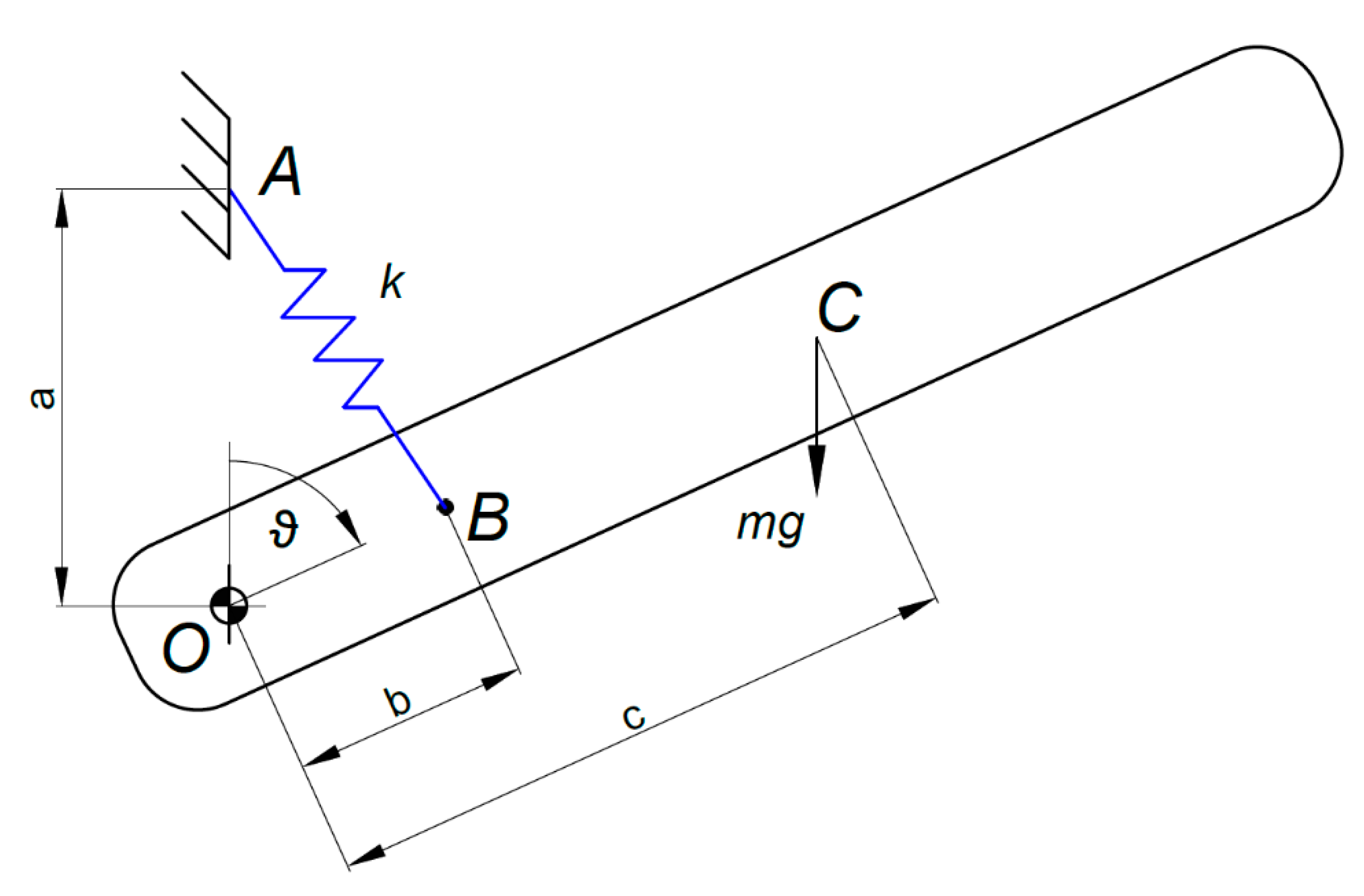
The system studied in this paper is a planar link with mass m, with a rotational degree of freedom defined by a hinge in point O (Figure 1). The distance between O and the center of mass of the link, C, is . To balance the system regardless of the configuration , a zero free-length spring, with stiffness , is anchored between point A (frame) and point B (link), defined respectively by the distances and with respect to the pivot O.
The total potential energy of the system, , is the sum of potential energy of the link and the elastic potential energy of the spring [8]:
To ensure that the system is in indifferent equilibrium, i.e., by imposing :
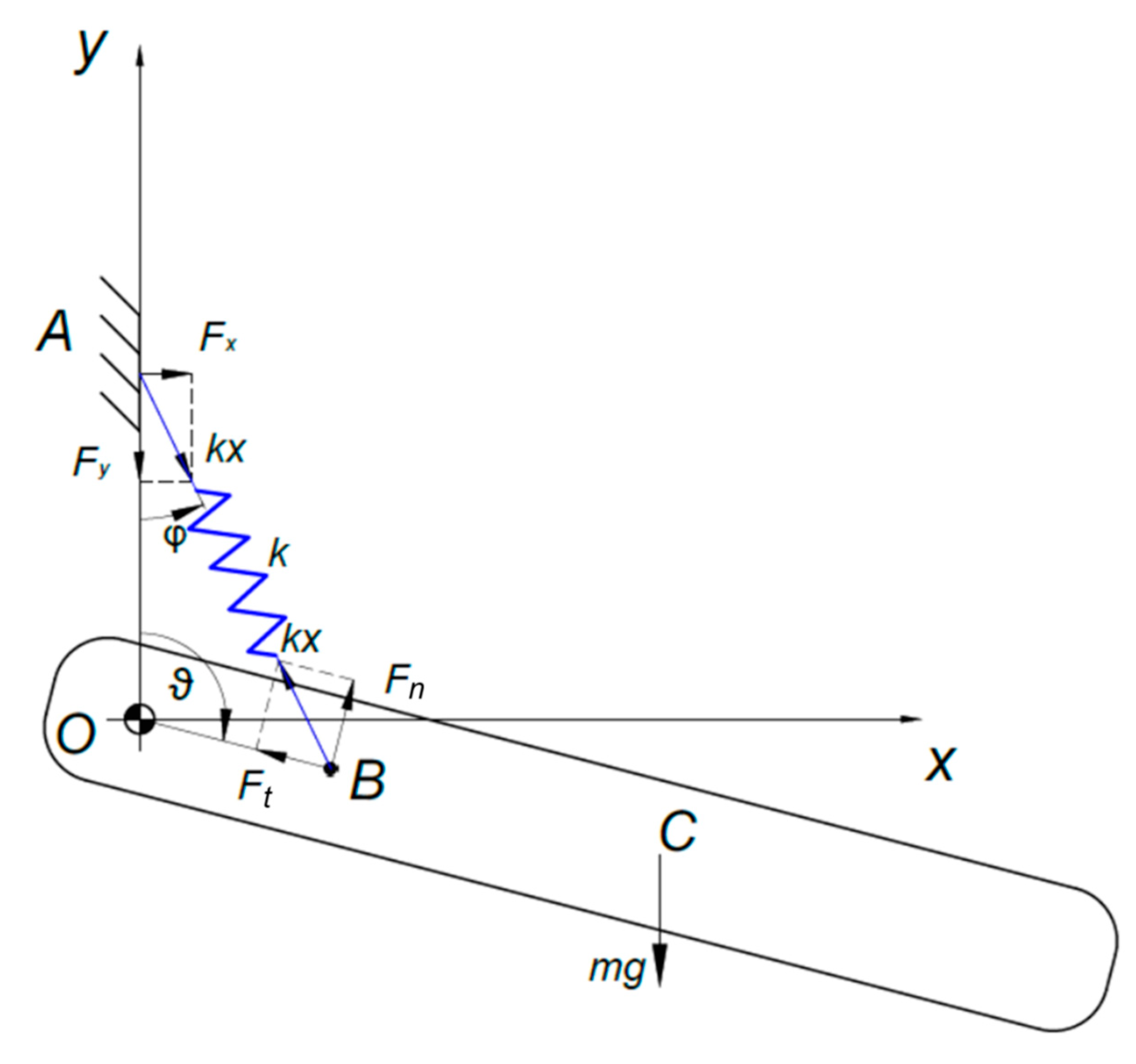
It is convenient to study the effects of the (zero free-length) spring force on the frame (A) and on the link (B). As shown in Figure 2, in points A and B the force is:
where the spring length is:
The force at point A may be split into and , whose expressions are not reported for the sake of brevity. More interestingly, the force at point B can be conveniently split into:
3. Self-Regulating Mechanism
If the mass changes, either the length or (or potentially both) should change to keep Equation (2) satisfied, maintaining the system in indifferent equilibrium. Theoretically, changes in could also be accommodated by changing the stiffness , but that would imply replacing the spring with another one each time the payload changes, which is impractical.
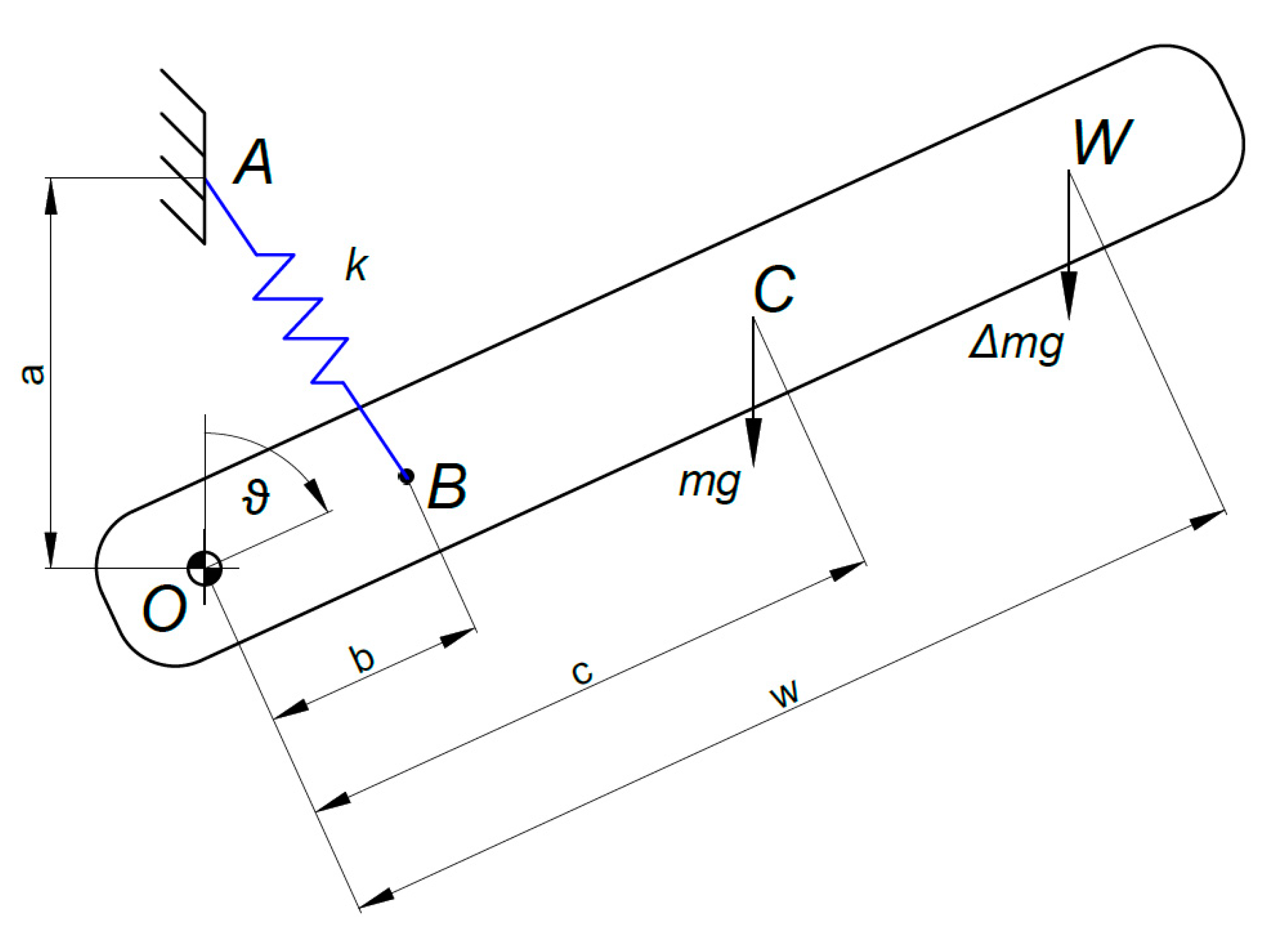
It is customary to consider variable payloads applied at potentially different positions along the link. Figure 3 shows the link with the addition of a generic payload at point W, i.e., at distance from O.
.
Again, to ensure that the mechanism remains in indifferent equilibrium, some of the spring anchoring points should be amended. This can be done by moving point B along the link. By adding the potential energy contribution of to Equation (1), Equation (2) changes into:
indicating that b should be changed into . Clearly, if , then and Equation (7) is reduced to Equation (2). Rearranging Equation (7) for :
showing a linear relationship between and (note that in case is fixed and is changed into , one obtains ).
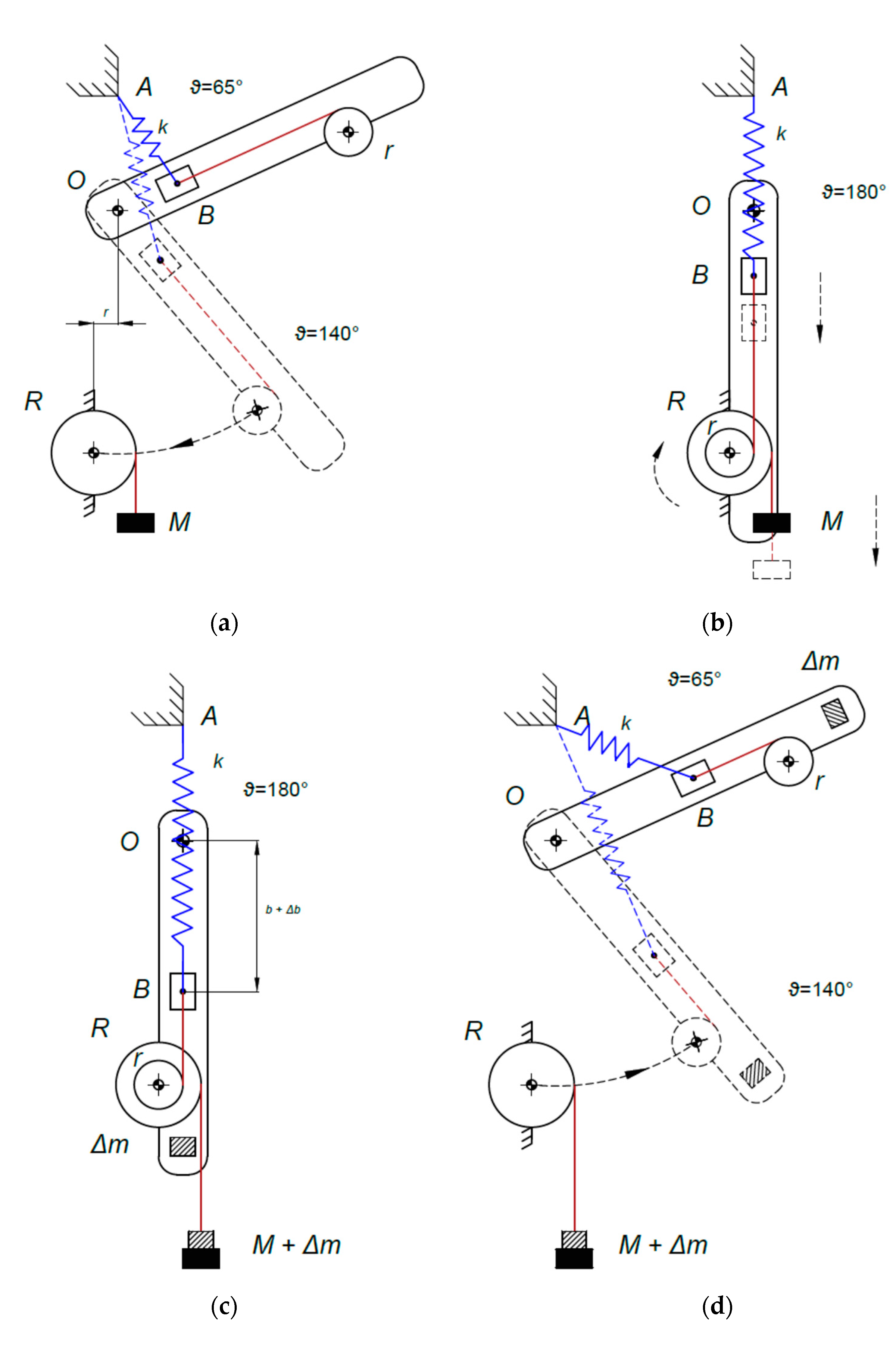
To achieve this, point B can be anchored to a slider able to move along the link, i.e., allowing a variable , regulated by an auxiliary mechanism. Such mechanism is made of two pulleys and a counterweight (Figure 4a). One pulley has radius and is fixed to the frame. The other pulley has radius and is integral with the link, in such a position that the slider and the pulley are connected by means of a wire parallel to the link. Another wire is used to attach the counterweight, with initial mass (the procedure to determine is in Section 4), to the fixed pulley.
The procedure can be summarized as follows (Figure 4):
- -
- Bring the link to the position (Figure 4a)
- -
- Connect the link to the pulley with radius and release the slider, which will not move because of Equation (10) (Figure 4b)
- -
- Add the new payload to the link, and add the same amount to the counterweight (Figure 4c)
- -
- Lock the slider to the link and the pulley with radius to the frame
- -
- The link is now in indifferent equilibrium with the new payload, and can move where required (Figure 4d)
The purpose of the counterweight is to fully balance the force when the payload is changed. Otherwise, would balance and move point B in an unpredictable manner. To ensure that the system is still in indifferent equilibrium with the new payload, Equation (8) must be satisfied, i.e., a specific is required.
According to Equation (5), depends on the configuration of the link, . So, a reference configuration for the link needs to be defined. In this paper, the reference position is defined as (Figure 4b). From Equations (4) and (5):
The moment balance around the pulley axis, when the two pulleys are fixed together, is:
which provides a relationship between the initial mass of the counterweight, , and the radiuses and .
Once the payload is added, the moment balance equation reads:
By using Equation (8) in Equation (11), and accounting for Equation (10):
which is simplified as:
4. Remarks and Simulation Results
The self-regulating mechanism allows us to vary the payload on the link while keeping the system in indifferent equilibrium. Essentially, three values need to be determined (, , ) while respecting two constraints (Equations (10) and (13)). can be immediately obtained as:
Hence, practically, the radiuses and must be chosen, ensuring their ratio is according to Equation (13).
Interestingly, the maximum payload that can be applied depends on the difference between the length of the link and the initial value of , since any payload produces an increase of , , as in Equation (8). It is more realistic to assume that the slider position cannot travel further than :
Consequently, the maximum applicable payload, , can be calculated combining Equations (15) and (8) and rearranging for :
Further interesting considerations can be made studying the effect of the additional payload on the length of the spring: by using Equation (8) into (4), considering that is replaced by :
which implies, for the same , an increase of with . This is also clear observing Figure 1 and bearing in mind that the presence of causes an increase of . As discussed above, is limited, and this is reflected in the spring length.
To validate the presented approach, a simple simulation is carried out for a system with the sample parameters listed in Table 1. The simulation includes the following steps:
- I.
- The link (in indifferent equilibrium since ), with no payload, is at for 4 s.
- II.
- Some payload needs to be added. The link moves to the configuration in 10 s.
- III.
- The link is connected to the pulley with radius the slider is released and the new payload, kg, is added. The mass of the counterweight is increased by the same amount. As a result, the slider moves to mm. All of this takes 3 s.
- IV.
- The slider is locked and the pulley with radius is disconnected—this takes another 3 s.
- V.
- The link is then required to reach the configuration in 10 s, and then it stays in that position for a while.
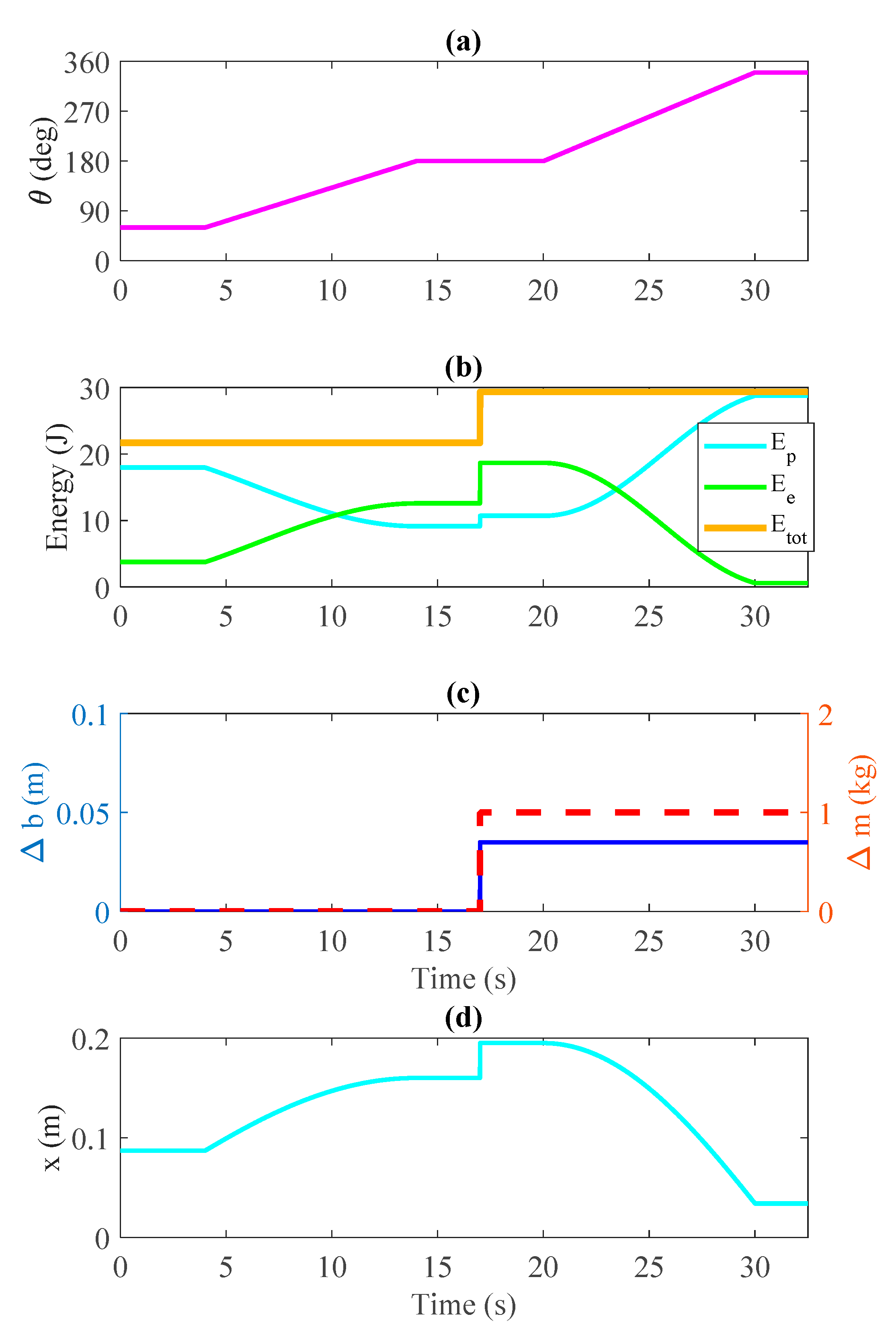
Figure 5 depicts the trends of the most relevant quantities. Specifically, Figure 5b shows the gravitational potential energy, , the elastic potential energy, , and the total energy, . During step I, obviously, they are constant. While varies in step II (Figure 5a, between 4 and 14 s), so do and , with their sum remaining constant, showing that the system is in indifferent equilibrium. At the end of step III, both and increase due to the variation of and respectively (Figure 5c). During step 5 (Figure 5a, between 20 and 30 s), again, and vary as varies, while remains constant at the value reached at the end of step III. This demonstrates that the system is again in indifferent equilibrium. Finally, Figure 5d shows the length of the spring which, according to Equation (17), is affected by both and . The design phase of the spring (e.g., wire diameter, coil diameter, number of coils, etc.) will need to take into account the potential variation in spring length, along with structural resistance considerations.
.
5. Conclusions
This paper presented a method to achieve passive gravity balancing for a 1-DOF link while accounting for variations of the payload. During standard operation, the manipulator is in neutral equilibrium, i.e., it will not move from whatever configuration the user puts it in. When the payload needs to be changed, the link is brought to a specific configuration, and then an auxiliary mechanism is exploited to automatically regulate one of the attachment points of the spring. Then, the link with the new payload is in equilibrium, again, regardless of the configuration.
Simulation results confirmed the effectiveness of the proposed approach in a generic scenario characterized by different link configurations and payloads.
Future works will be devoted to the development and to the validation of a physical prototype of the proposed architecture. The possibility of modifying the proposed approach to overcome the use of counterweights will be investigated.
Author Contributions
Conceptualization, D.F., G.B. and B.L.; methodology, D.F., G.B. and B.L.; investigation, D.F., G.B. and B.L.; writing—original draft preparation, D.F., G.B. and B.L.; writing—review and editing, D.F., G.B. and B.L.; All authors have read and agreed to the published version of the manuscript.
Funding
This research received no external funding.
Institutional Review Board Statement
Not applicable.
Informed Consent Statement
Not applicable.
Data Availability Statement
Not applicable.
Conflicts of Interest
The authors declare no conflict of interest.
References
- Keung, G.; Chen, C. Novel Design of an Adjustable Constant Force Mechanism Based on Cam and Spring. In IFToMM World Congress on Mechanism and Machine Science; Springer International Publishing: Cham, Switzerland, 2019; pp. 1481–1490. [Google Scholar]
- Lenzo, B.; Zanotto, D.; Vashista, V.; Frisoli, A.; Agrawal, S. A new Constant Pushing Force Device for human walking analysis. In Proceedings of the 2014 IEEE International Conference on Robotics and Automation (ICRA), Hong Kong, China, 3 May 2014; pp. 6174–6179. [Google Scholar]
- Ou, M.; Qi, L.; Jesse, M.; Ken, R. Concepts Study of a Passive Reduced-Gravity Simulator for Training Astronauts. In Proceedings of the ASME Design Engineering Technical Conference, Montreal, QC, Canada, 15–18 August 2010. [Google Scholar]
- Banala, S.K.; Agrawal, S.K.; Fattah, A.; Rudolph, K.; Scholz, J. A gravity balancing leg orthosis for robotic rehabilitation. In Proceedings of the IEEE Conference (ICRA 2004), New Orleans, LA, USA, 26 April–1 May 2004. [Google Scholar]
- French, M.J.; Widden, M.B. The spring-and-lever balancing mechanism, George Carwardine and the Anglepoise lamp. Proc. Inst. Mech. Eng. Part C J. Mech. Eng. Sci. 2000, 214, 501–508. [Google Scholar] [CrossRef] [Green Version]
- Herder, J.L.; Tuijthof, G.J.M. Two Spatial Gravity Equilibrators. In Proceedings of the ASME Design Engineering Technical Conference, MECH-14120, Baltimore, MD, USA, 10–13 September 2000. [Google Scholar]
- Lenzo, B.; Fontana, M.; Marcheschi, S.; Salsedo, F.; Frisoli, A.; Bergamasco, M. Trackhold: A novel passive arm-support device. J. Mech. Robot. 2016, 8, 021007. [Google Scholar] [CrossRef] [Green Version]
- Lee, G.; Lee, D.; Oh, Y. One-piece gravity compensation mechanism using cam mechanism and compression spring. Int. J. Precis. Eng. Manuf.-Green Technol. 2018, 5, 415–420. [Google Scholar] [CrossRef]
- Chheta, Y.R.; Joshi, R.M.; Gotewal, K.K.; Manoah, S.M. A Review on Passive Gravity Compensation. In Proceedings of the International Conference on Electronics, Communication and Aerospace Technology (ICECA 2017), Coimbatore, India, 20–22 April 2017. [Google Scholar]
- Agrawal, S.; Fattah, A. Gravity-balancing of spatial robotic manipulators. Mech. Mach. Theory 2004, 39, 1331–1344. [Google Scholar] [CrossRef]
- Franco, J.A.; Gallego, J.A.; Herder, J.L. Static Balancing of Four-Bar Compliant Mechanisms with Torsion Springs by Exerting Negative Stiffness Using Linear Spring at the Instant Center of Rotation. J. Mech. Robot. 2021, 13, 031010. [Google Scholar] [CrossRef]
- Barents, R.; Schenk, M.; van Dorsser, W.D.; Wisse, B.M.; Herder, J.L. Spring-to-spring balancing as energy-free adjustment method in gravity equilibrators. J. Mech. Des. 2011, 133, 061010. [Google Scholar] [CrossRef]
- Agrawal, A.; Agrawal, S.K. Design of gravity balancing leg orthosis using non-zero free length springs. Mech. Mach. Theory 2005, 40, 693–709. [Google Scholar] [CrossRef]
- Zhang, Y.; Arakelian, V.; Le Baron, J.P. Linkage Design for Gravity Balancing by Means of Non-zero Length Springs. In ROMANSY 22-Robot Design, Dynamics and Control; Springer International Publishing: Cham, Switzerland, 2019; pp. 163–170. [Google Scholar]
- Delissen, A.A.; Radaelli, G.; Herder, J.L. Design and optimization of a general planar zero free length spring. Mech. Mach. Theory 2017, 117, 56–77. [Google Scholar] [CrossRef] [Green Version]
- Lenzo, B.; Frisoli, A.; Salsedo, F.; Bergamasco, M. New gravity balancing technique and hybrid actuation for spatial serial manipulators. In Advances in Robot Kinematics; Springer International Publishing: Cham, Switzerland, 2014; pp. 419–427. [Google Scholar]
- Rahman, T.; Ramanathan, R.; Seliktar, R.; Harwin, W. A Simple Technique to Passively Gravity-Balance Articulated Mechanisms. J. Mech. Des. 1995, 117, 655–658. [Google Scholar] [CrossRef]
- Lenzo, B. Gravity balancing of a spatial serial 4-dof arm without auxiliary links using minimum number of springs. In Proceedings of the AIMETA XXIII Conference-The Italian Association of Theoretical and Applied Mechanics, Salerno, Italy, 4–7 September 2017. [Google Scholar]
- Deepak, S.R.; Ananthasuresh, G.K. Static balancing of spring-loaded planar revolute-joint linkages without auxiliary links. In Proceedings of the 14th National Conference on Machines and Mechanism (NaCoMM09), Durgapur, India, 18 December 2009. [Google Scholar]
- Wisse, B.M.; Van Dorsser, W.D.; Barents, R.; Herder, J.L. Energy-free adjustment of gravity equilibrators using the virtual spring concept. In Proceedings of the 2007 IEEE 10th International Conference on Rehabilitation Robotics, Noordwijk, The Netherlands, 13–15 June 2007; pp. 742–750. [Google Scholar]
- Van Der Wijk, V.; Herder, J.L. Force balancing of variable payload by active force-balanced reconfiguration of the mechanism. In Proceedings of the 2009 ASME/IFToMM International Conference on Reconfigurable Mechanisms and Robots, London, UK, 22–24 June 2009; pp. 323–330. [Google Scholar]
- Takesue, N.; Ikematsu, T.; Murayama, H.; Fujimoto, H. Design and prototype of variable gravity compensation mechanism (VGCM). J. Robot. Mechatron. 2011, 23, 249–257. [Google Scholar] [CrossRef]
- Shieh, W.B.; Chen, C.K. Conceptual Design of a Two-Stage Variable Gravity Compensated Mechanism. In IFToMM World Congress on Mechanism and Machine Science; Springer International Publishing: Cham, Switzerland, 2019; pp. 1535–1543. [Google Scholar]
- Chew, D.X.; Wood, K.L.; Tan, U. Design of a passive self-regulating gravity compensator for variable payloads. J. Mech. Des. 2019, 141. [Google Scholar] [CrossRef]
- Nguyen, V.L.; Lin, C.-Y.; Kuo, C.-H. Gravity compensation design of planar articulated robotic arms using the gear-spring modules. J. Mech. Robot. 2020, 12, 031014. [Google Scholar] [CrossRef]
- Nguyen, V.L.; Lin, C.-Y.; Kuo, C.-H. Gravity compensation design of Delta parallel robots using gear-spring modules. Mech. Mach. Theory 2020, 154, 104046. [Google Scholar] [CrossRef]
- Gatti, G.; Carbone, G. Gravity Compensation of Robotic Manipulators Using Non-linear Spring Configurations, Mechanisms and Machine Science 91; Springer: Cham, Switzerland, 2021; pp. 310–317. [Google Scholar]
- Woo, J.; Seo, J.T.; Yi, B.J. A static balancing method for variable payloads by combination of a counterweight and spring and its application as a surgical platform. Appl. Sci. 2019, 9, 3955. [Google Scholar] [CrossRef] [Green Version]
- Chiang, W.H.; Chen, D.Z. Design of planar variable-payload balanced articulated manipulators with actuated linear ground-adjacent adjustment. Mech. Mach. Theory 2017, 109, 296–312. [Google Scholar] [CrossRef]
- Chu, Y.L.; Kuo, C.H. A single-degree-of-freedom self-regulated gravity balancer for adjustable payload. J. Mech. Robot. 2017, 9, 021006. [Google Scholar] [CrossRef]
Figure 1.
Single DOF link with balancing zero free-length spring.

Figure 2.
Analysis of the forces applied by the spring to the link and frame.

Figure 3.
Single DOF link, no longer balanced due to the added payload .

Figure 4.
(a) The system is in indifferent equilibrium, and the auxiliary mechanism is fixed to the frame; (b) The link is fixed on the auxiliary mechanism. (c) Variation of the load on the link and variation on the counterweight. (d) The system is in the new configuration of equilibrium, and the auxiliary mechanism is fixed on the frame.

Figure 5.
Results of the simulation: (a) link configuration; (b) potential energy, elastic energy and total energy; (c) variation and payload ; (d) spring length .
Figure 5.
Results of the simulation: (a) link configuration; (b) potential energy, elastic energy and total energy; (c) variation and payload ; (d) spring length .


Table 1.
Parameters of the simulated system.
| Quantity | Symbol | Value and Unit |
|---|---|---|
| Mass of the link | 3 kg | |
| Distance between point O and W | 0.35 m | |
| Distance between points O and A | 0.1 m | |
| Distance between points O and B | 0.06 m | |
| Distance between O and C | 0.2 m | |
| Radius of pulley integral with the frame | 0.035 m | |
| Radius of the pulley integral with the link | 0.01 m | |
| Spring stiffness | 981 N/m |
Publisher’s Note: MDPI stays neutral with regard to jurisdictional claims in published maps and institutional affiliations. |
© 2021 by the authors. Licensee MDPI, Basel, Switzerland. This article is an open access article distributed under the terms and conditions of the Creative Commons Attribution (CC BY) license (https://creativecommons.org/licenses/by/4.0/).
Share and Cite
MDPI and ACS Style
Franchetti, D.; Boschetti, G.; Lenzo, B. Passive Gravity Balancing with a Self-Regulating Mechanism for Variable Payload. Machines 2021, 9, 145. https://0-doi-org.brum.beds.ac.uk/10.3390/machines9080145
AMA Style
Franchetti D, Boschetti G, Lenzo B. Passive Gravity Balancing with a Self-Regulating Mechanism for Variable Payload. Machines. 2021; 9(8):145. https://0-doi-org.brum.beds.ac.uk/10.3390/machines9080145
Chicago/Turabian StyleFranchetti, Diego, Giovanni Boschetti, and Basilio Lenzo. 2021. "Passive Gravity Balancing with a Self-Regulating Mechanism for Variable Payload" Machines 9, no. 8: 145. https://0-doi-org.brum.beds.ac.uk/10.3390/machines9080145
Note that from the first issue of 2016, this journal uses article numbers instead of page numbers. See further details here.