
Reconfigurable Machine Tool Design for Box-Type Part Families


1
School of Mechanical and Precision Instrument Engineering, Xi’an University of Technology, Xi’an 710048, China
2
School of Mechanical Engineering, HuBei University of Automotive Technology, Shiyan 442002, China
*
Author to whom correspondence should be addressed.
Machines 2021, 9(8), 148; https://0-doi-org.brum.beds.ac.uk/10.3390/machines9080148
Submission received: 30 May 2021
/
Revised: 22 July 2021
/
Accepted: 27 July 2021
/
Published: 29 July 2021
(This article belongs to the Special Issue Robotic Machine Tools)
Abstract
:The reconfigurable manufacturing system (RMS) is a new manufacturing technology and paradigm that resolves the contradictions regarding high efficiency, low cost and flexible production in the mass production of part families. Reconfigurable machine tools (RMTs) are the core components of RMSs. A new approach is proposed for the design of RMTs, which is closely related to the process planning of a given box-type part family. The concepts of the processing unit and the processing segment are presented; they are not only the basic elements of the processing plans of machined parts, but also closely related to the structural design of RMTs. Processing units created by processing features can be combined into various processing segments. All the processing units of one processing segment correspond to the machining operations performed by one RMT. By arranging the processing segments according to the processing sequence, a variety of feasible processing plans for a part can be obtained. Through analysis of the established similarity calculation model for processing plans, the most similar processing plans for the parts in a given part family can be determined and used for the structural design of RMTs. Therefore, the designed RMTs can achieve rapid conversion of processing functions with the least module replacement or adjustment to realize the production of the parts in the part family. Taking the production of a gearbox part family as an example, the validity of the presented method is verified.
1. Introduction
With the continuous development of the global economy, the updating of products has become faster and faster and enterprises are increasingly facing unpredictable market changes. These changes include the high-frequency introduction of new products, new product demand, new process technologies, etc. [1]. To survive in this new manufacturing environment, companies must be able to react to changes rapidly and cost-effectively [2]. In the mid-1990s, Koren and other researchers at the University of Michigan in the United States proposed a new type of factory with a “reconfigurable manufacturing system” as a new system architecture to solve the problem of fierce competition in the global manufacturing industry regarding the mass production of multiple varieties of products. As a new type of manufacturing system, the RMS can quickly and economically change its system structure and resource allocation so that the system can obtain precise functions and the capacity to meet production requirements at any time [3].
In the production process, machine tools are critical, and their reconfigurable ability and work performance are crucial to the construction of high-quality and -efficiency reconfigurable manufacturing systems. Therefore, companies need advanced modular machine tools and corresponding reconfigurable manufacturing systems to quickly respond to rapidly changing market demands such as drastic changes in product varieties and product quantities [4]. In current, traditional manufacturing systems, there are two types of machine tools: dedicated machine tools (DMTs) and computer numeric controlled tools (CNCs). Because DMTs are customized for a certain process corresponding to one type of product, they take the least resources (no functional redundancy) and have low cost. Therefore, they have high throughput and efficiency in batch processing [5]. In contrast, CNCs have a large reserve of functions and can respond to different processing requirements. CNCs, however, require a large investment and do not have the advantages of low cost and high efficiency over DMTs in batch processing, but they are suitable for multi-variety, single-piece and small-batch product processing [6]. In this context, Koren et al. [5] at the University of Michigan, put forward the concept of a reconfigurable machine tool. Since then, as one of the core reconfiguration technologies to realize RMS application, the design method for RMTs has always been a research hotspot and also a research difficulty. The design of the RMT is usually focused on a specific part family and should be rapidly adjustable to changes in its structure and/or operations to manufacture various parts of that part family [3,7]. For this reason, RMTs are core components of future intelligent manufacturing systems [8]. Consequently, studies of the design methodology of RMTs have far-reaching practical significance for the transformation of traditional manufacturing industries and the construction of reconfigurable manufacturing systems [9].
Application of RMTs can realize the processing conversion of machined parts in a given part family. The processing plans of the parts directly affect the configuration of the RMT functional modules and the choice of RMT reconfiguration schemes. Therefore, research on the process planning method for part families in reconfigurable manufacturing will be of great significance for the reasonable and effective design of RMTs and RMSs [10]. At present, there has already been a lot of research on reconfigurable manufacturing system and the modular design of machine tools [11,12,13,14,15,16,17,18,19]. Among the research, the concept of the delayed reconfigurable manufacturing system (D-RMS) was proposed to improve the convertibility of RMSs by grouping parts with common former operations into the same part family and selecting appropriate machine types including dedicated machines, flexible machines, and reconfigurable machines [12]. A reconfigurable machine tool that provided a flexible platform for turning and milling was invented [13]. According to the production demand, the study of reconfigurable drilling machine selection and process parameter optimization was carried out [14]. A new class of reconfigurable parallel kinematic machines [17] and reconfigurable micro-machine tools for desktop machining micro-factories [18] were designed. A method for selecting RMT modules based on RMT ontology was proposed [20] in which the appropriate RMT modules were selected according to the established knowledge base, and the selection of RMT modules was studied according to RMT performance indicators. Ming et al. proposed a highly efficient calculation method for sensitive, position-dependent geometric error (PDGE) identification of a five-axis reconfigurable machine tool [21]. Using this method, sensitive PDGEs can be calculated directly according to a mapping expression, which eliminates the process of error modeling and analysis. A multi-objective optimization method for the RMT based on the cuckoo search algorithm was proposed [22], and there were two proposed objective functions: minimizing the design cost of the RMS and maximizing the reconfiguration index so as to design an RMS with a low cost and high reconfigurable capability. Various research on RMTs is primarily in three areas: architecture design, configuration design and optimization, and system integration and control [23]. Most of the research focuses on optimizing existing production lines to save costs and increase production capacity [3,24,25]. There are still a number of issues that need to be further addressed for developing implementable industrial RMTs. The design of RMTs is closely related to reconfigurable manufacturing process planning [2], but there is still a lack of design research that combines the two closely, which makes it difficult to verify the practical application of RMSs [23]. Although the concept of RMT was proposed in the year 2020 as one key technology for the future of manufacturing [26], it still lacks broad application now. One reason is the necessary technological progress, especially regarding the hardware of machine tools [27].
The function of each RMT is customized according to the processing plans of the machined parts. That is to say, these processing plans directly affect the structure design and the overall performance of RMTs. Therefore, in the RMT design stage, determining the parallel design method an RMT is closely related to for part family process planning will be of great significance for obtaining RMTs that can not only meet the processing demand of the part family, but also achieve rapid processing conversion between parts. In this paper, based on the structural characteristics of RMTs, a new RMT design method based on the process planning of box-type part families is presented. Taking the production of a gearbox part family as an example, the effectiveness of this method is verified.
2. Processing Characteristics of Box-Type Parts
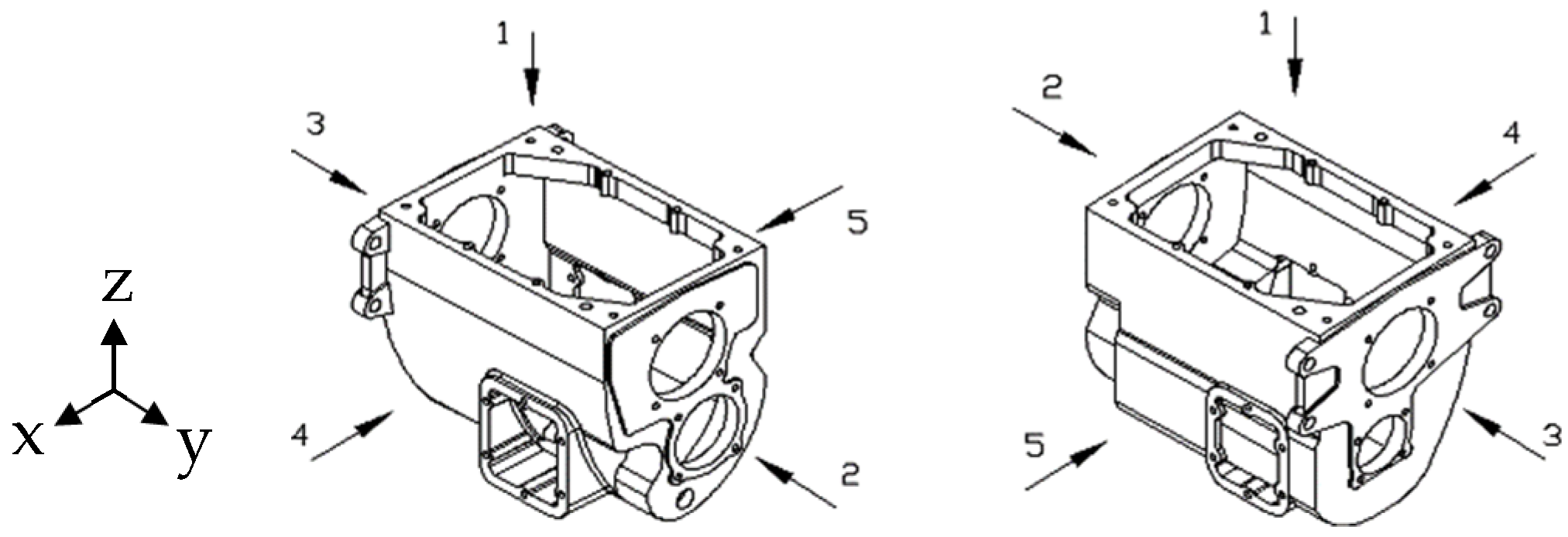
In mechanical products, box-type parts such as an automobile-gearbox housing are mainly used to install, contain, and support other parts, as shown in Figure 1.
The function of a box-type part determines its complex shape, thin wall, large size, heavy weight, high strength, and good rigidity. Generally, the machining accuracy of box-type parts is relatively high, and there are many surfaces and holes to be machined on this kind of part. There are complicated shape–position relationships between machined surfaces, machined holes, machined surfaces, and the machined holes of the part. The processing of box-type parts is complicated and difficult and has many working procedures, so this kind of part is a typical representative of complex machining parts.
Because box-type parts have complex shapes and many machining features and belong to thin-walled parts, their machining-locating datums can be divided into two categories: rough machining-locating datums and finishing-locating datums. When this kind of part is mass produced, one plane and two holes are usually selected as the unified finishing-locating datum as much as possible so as to ensure the machining accuracy of the part and facilitate the clamping of the workpiece. In order to ensure the size and geometric accuracy of the holes and planes on the part, the following processing principles should generally be followed: The processing features used as the locating datums must be processed first, before other processing features. The plane features must be processed firstly, and then their hole features them can be processed stably and reliably through plane locating, which can also reduce the installation deformation of the workpiece and improve the processing accuracy of the holes. Due to the thin wall, low rigidity, and easy deformation of box-type parts, the cutting forces and cutting heat generated by rough machining are relatively large, so the rough machining and finish machining of such parts should be carried out separately. In order to reduce the number of machine tools, thereby improving production efficiency and processing accuracy and reducing processing costs, all holes on one surface should be processed together to the maximum extent. Especially in mass processing, the benefits of process concentration are particularly obvious.
3. Part Process Planning Closely Related to RMT Design
To complete the processing of a machined part, the first step is to obtain its processing plan, which means to determine all processing methods used and their corresponding processing sequence. The processing functions of the designed machine tools must be able to meet all the processing requirements of the part processing plan.
3.1. Establish the Mapping Relationship between the Part Processing Plan and the Machine Tool Processing Functions
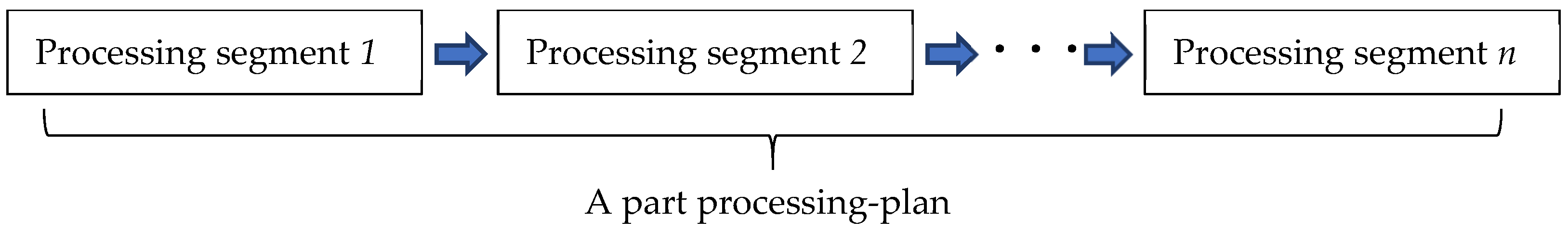
The RMT is a kind of non-redundant function machine tool that can precisely meet the processing requirements of a machined part and has high processing economy. Moreover, RMTs can perform rapid processing conversion among parts in a specific part family through structural reconstruction and have processing flexibility for part family production. Therefore, establishing a process planning method for specific part family production that closely considers the RMT design is the key to realizing the practical application of RMTs. A new method of process planning for part-families is proposed herein. As shown in Figure 2, a part-processing plan consists of several processing segments arranged according to their processing sequence. All machining operations corresponding to a processing segment will be performed by an RMT.
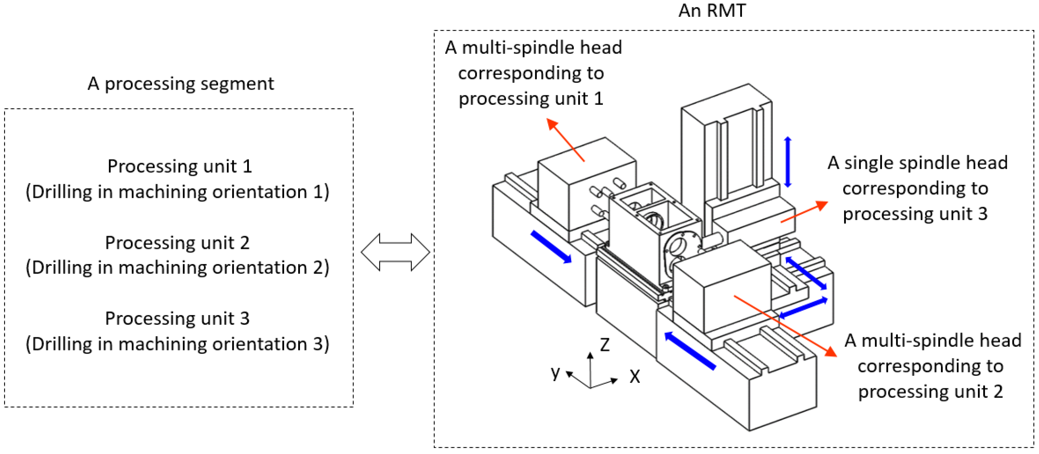
The mapping relationship between a processing segment and its corresponding RMT is shown in Figure 3. An RMT is usually composed of multiple processing units corresponding to various machining orientations. For each processing unit, a single spindle head or a multi-spindle head may be used to complete different types of machining operations such as drilling, boring, tapping, etc.
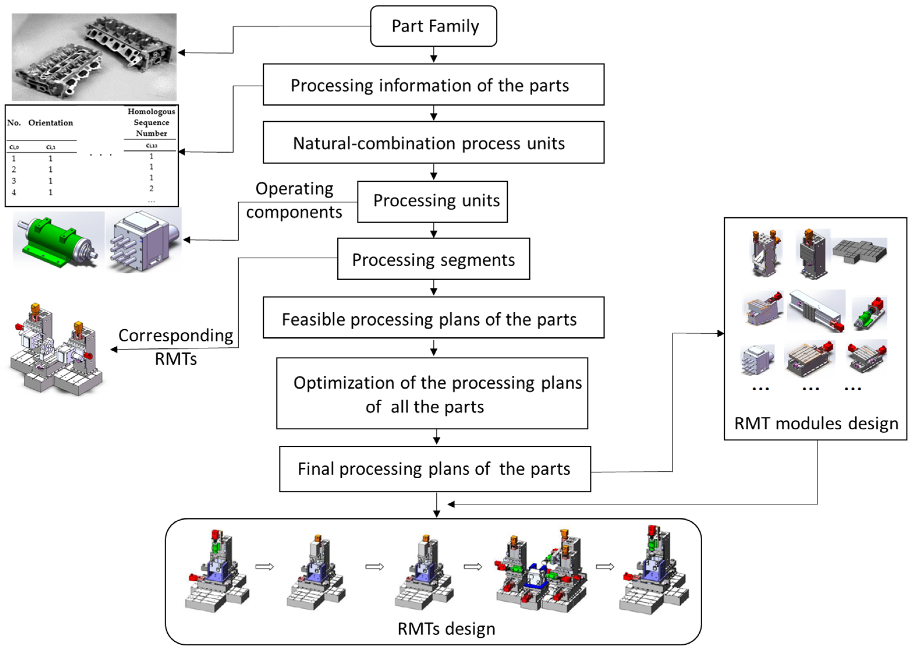
In order to realize rapid processing conversion among the parts in the part family, the processing plans for all the parts in the part family must be optimized and selected as an important basis for the RMT design. Then, based on the design of the RMT module groups for the production of a specific part family, RMT structure schemes can be generated according to their processing function requirements. A general scheme of the design methodology of reconfigurable machine tools is shown in Figure 4.
3.2. Acquisition of the Processing Information of the Part
In order to quickly create the processing plans for the parts in a part family, it is necessary to establish a computer-aided process planning method. First, all processing information for the part needs to be extracted totally. By analyzing the final structure’s features and the processing technical requirements of the part, its final processing features can be obtained. After tracing the final processing features layer by layer, all required pre-processing features of the part can be determined. Finally, a processing information table containing all processing features of the part is established.
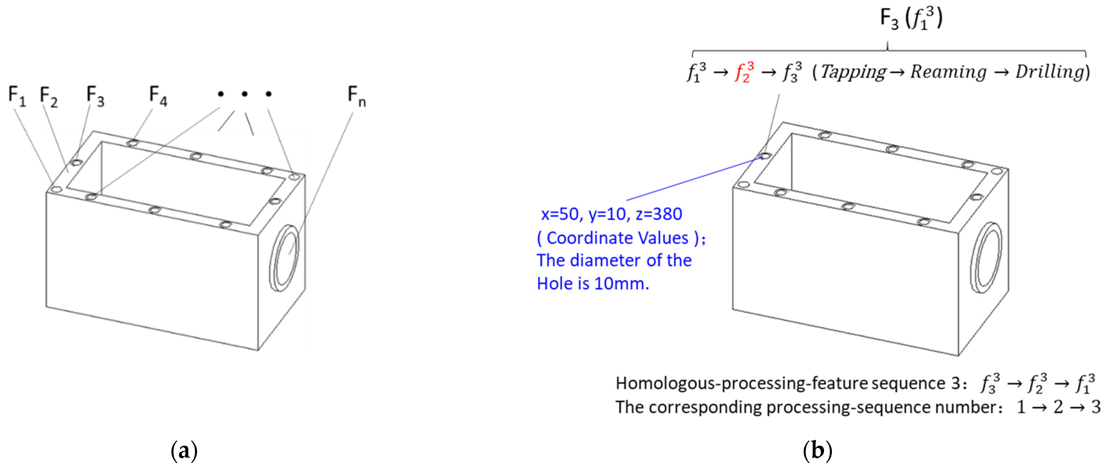
As shown in Figure 5a, all final processing features of the part are directly obtained by analyzing the detailed drawing to form a processing feature set indicated by A, which is described in Equation (1):
represents the ith final processing feature of the machined part in set A, and n is the total number of the final processing features, i = 1…n.
The second step is to trace back all of the pre-processing features from each final processing feature. Taking the ith final processing feature as an example, all the processing features obtained can form a processing feature set (including ) as in Equation (2):
is the total number of the processing features in set . For example, if a final processing feature of a machined part is finish boring, the pre-processing features are rough boring and semi-finish boring; that is,.
For ease of description, the definition of homogeneous processing features is given herein; that is, a series of processing features that belong to a processing feature set are collectively referred to as homogeneous processing features. A final processing feature may be traced back to a plurality of homologous processing features, which can form a homologous processing feature sequence in the order of processing, such as the example shown in Figure 5b. Obviously, homogenous processing features have the same spatial position coordinates.
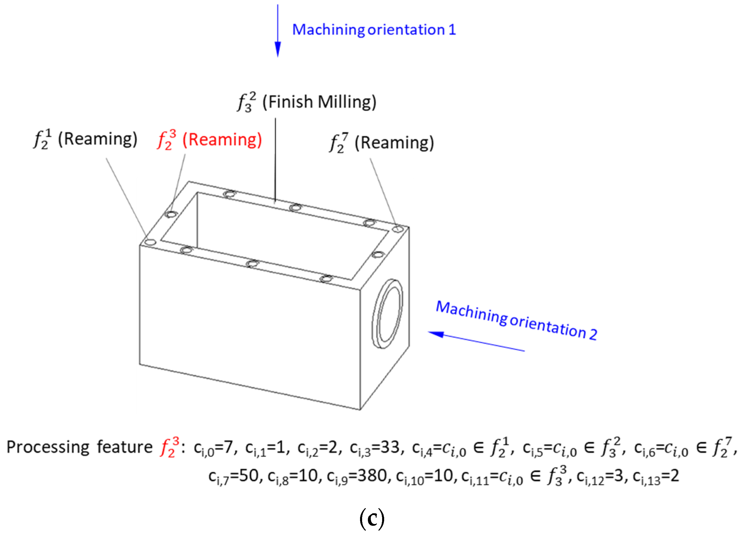
The third step is to create a processing information table for the machined part. Here, it is specified that the table is created for each single value, as shown in Figure 6, which contains the processing information for the processing features. Fourteen kinds of processing information, which are represented by numbers, are included in each row. Among them, ci,0 represents the code of a processing feature, ci,1 indicates the machining orientation corresponding to the processing feature (ci,1 = 1, 2, …, 7), 1~6 represent the machining orientations along the coordinate axis in the Cartesian coordinate system, respectively, and 7 represents the oblique machining orientation that is inclined to the coordinate axis. Figure 1 illustrates an automobile gearbox housing with six machining orientations. ci,2 is the feature type code (=1 means plane machining and =2 means inner surface machining, mainly for various hole machining such as unthreaded hole machining, threaded hole machining, etc.). ci,3 is the processing type code (=11 means the rough milling, =12 means the finishing milling, =21 means the rough boring, =22 means the finish boring, etc.). The codes ci,4, ci,5, ci,6 represent three locating datums of a processing feature, respectively; that is, the codes correspond to other processing features used as the locating datums, and if the locating datums of rough processing features are non-processing features, the codes are assigned values of 0. ci,7, ci,8, ci,9 are the X, Y, and Z coordinate values of a processing feature in the overall coordinate system respectively. If the processing feature is a hole-machining feature, ci,10 represents the diameter value of the hole; otherwise, it is assigned a value of 0. ci,11 corresponds to a processing feature that must be processed before the current processing feature according to the basic principles of the processing sequence, which expresses the processing sequence relationship between the two processing features. Code ci,11 is also called the sequence label. The homologous processing feature sequences are represented by numerical symbols. Code ci,12 is the numerical symbol of the homologous processing feature sequence to which the current processing feature belongs. Code ci,13 is the processing sequence number of the current processing feature in its homologous processing feature sequence. For example, the homologous processing feature sequence mentioned above includes the three processing features of rough boring, semi-finish boring, and finish boring; their codes, ci,13, are 1, 2, and 3 respectively such as in an example shown in Figure 5c. The processing information table of the part will be used as the basis for its process planning.
3.3. The Creation of Processing Units
RMTs can be split into a set of autonomous functional modules that can be plug-and-play interfaced to form complete systems for particular needs [2]. In order to realize the rapid reconstruction of the structures and functions of RMTs, each autonomous functional module should have a specific processing function such as performing a definite machining operation. For an autonomous functional module with processing functions, the component that performs the machining operations may be a single spindle head or a multi-spindle head. On an RMT, there may be multiple operating components corresponding to the processing units of a processing segment of a machined part, and they operate in parallel and enable the RMT to achieve high-efficiency processing like a dedicated machine tool.
As shown in Figure 7, in general, there may be several processing units that constitute a processing segment, and several processing segments combine into the processing plan of a machined part. Therefore, a processing unit refers to a set of processing features that have the same feature type, locating datums, and machining orientation with no processing conflicts between them.
The processing units can be established according to the processing information table of the machined part. First, the processing features that have the same processing type, locating datums, and machining orientation are combined into a natural combination process unit. Second, the natural combination process units are combined into form a processing unit by five principles as follows:
- (1)
- The processing unit must be formed by the natural combination process units that have the same machining orientation.
- (2)
- Natural combination process units with large processing differences cannot be combined into processing units. In general, planar machining features and hole machining features cannot be combined and rough machining features and finish machining features cannot be combined. For example, due to the large differences in cutting force, cutting vibration, etc., rough milling and fine milling cannot be combined; otherwise, the quality of the finishing surface will decrease.
- (3)
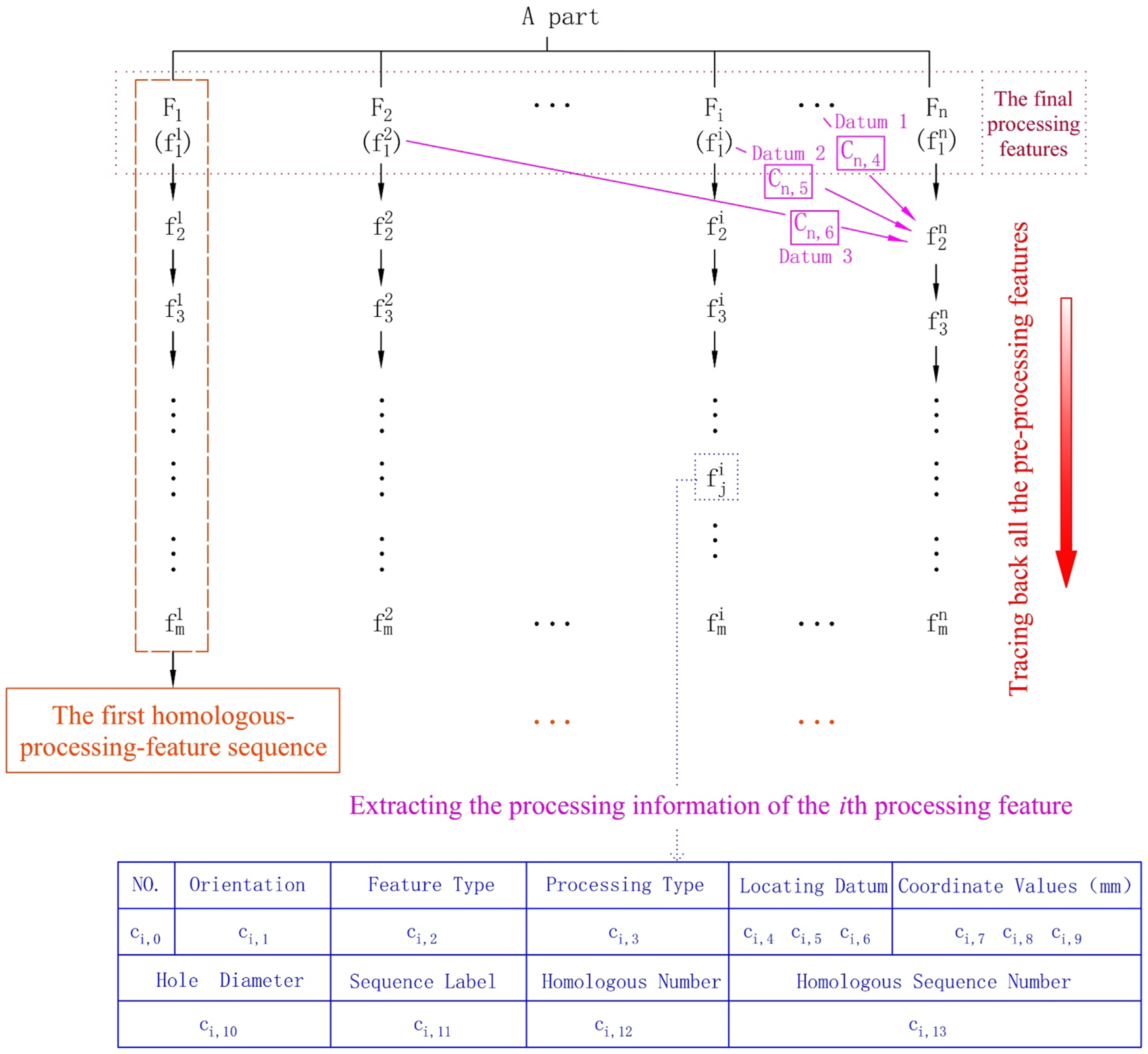
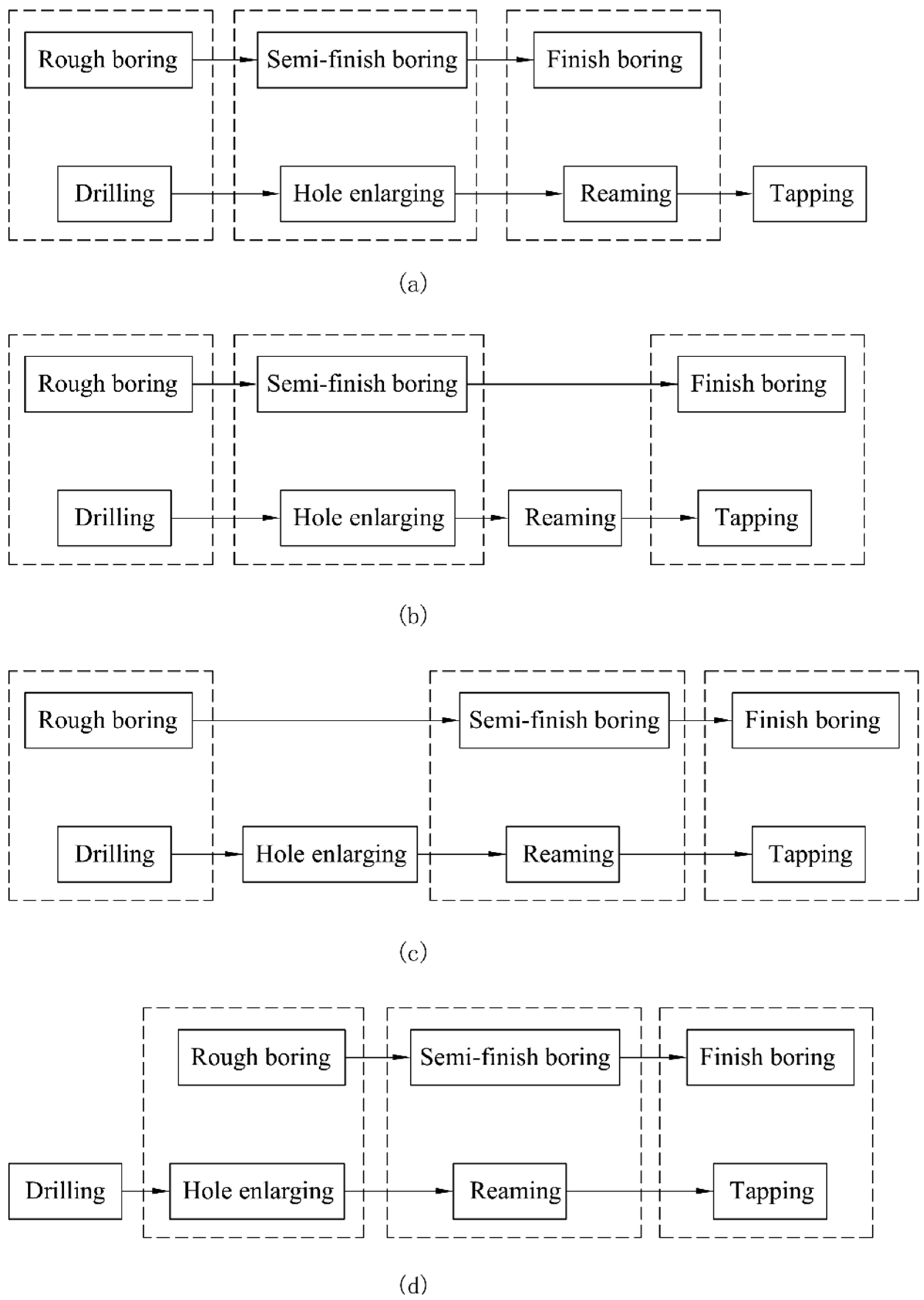
- There must be no processing sequence conflicts between the natural combination process units to be combined. For example, natural combination process units that contain homologous processing features cannot be combined because they have clear pre- and post-processing sequential relationships. In the four cases shown in Figure 8, the natural combination process units without homologous relationships can be combined into multiple processing units, and the processing features to be combined are enclosed by a rectangular dashed frame.
- (4)
- The locating datums of the natural combination process units to be combined cannot conflict with each other. Whether the natural combination process units can be combined or not should be judged and determined by the three locating datum codes they contain.
- (5)
- If the machining operations corresponding to a processing unit are performed by a multi-spindle head, all of the processing features contained therein must meet the minimum spindle spacing condition and the feed rate consistency condition.
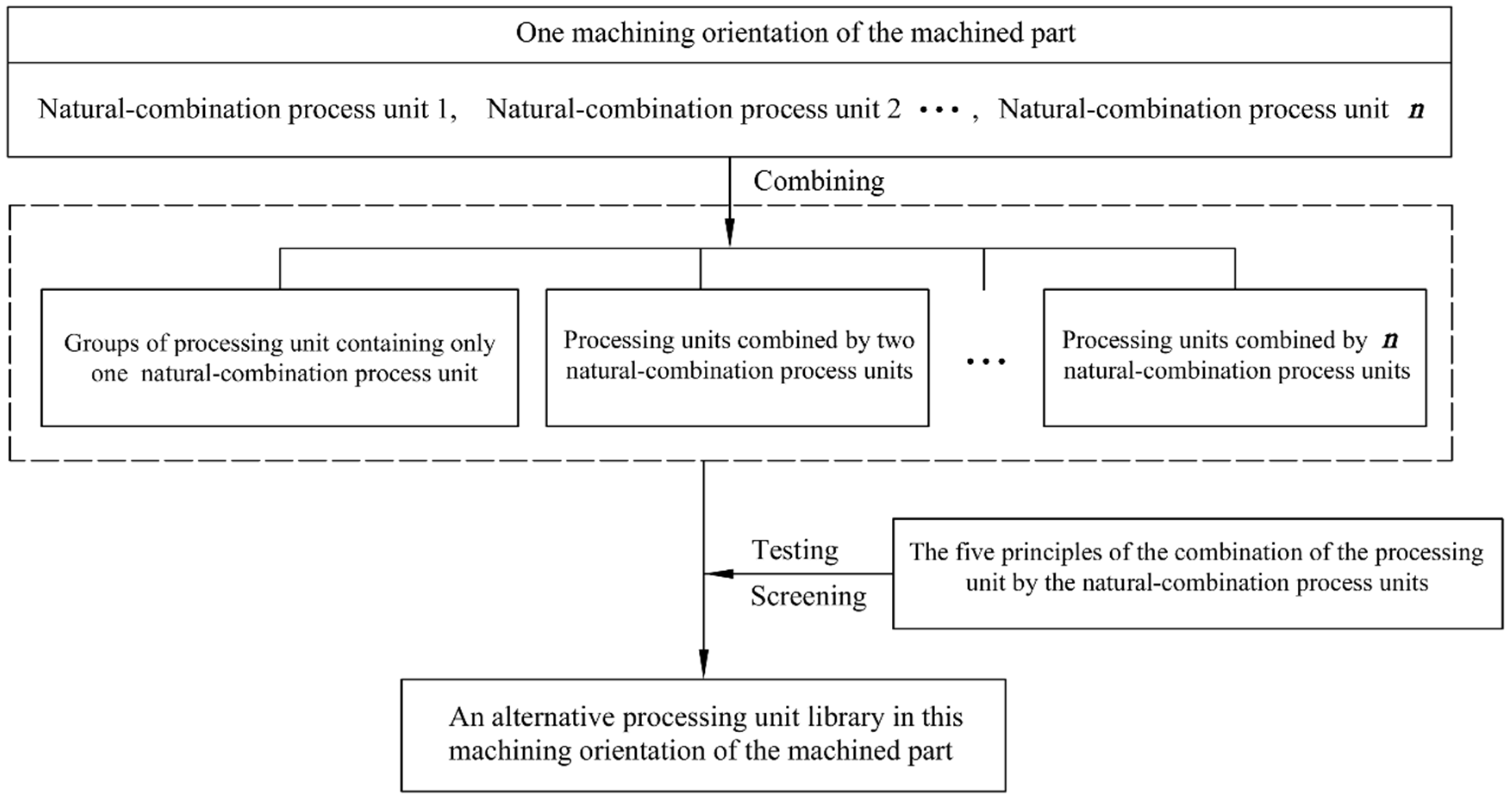
All feasible processing units must be created in each machining orientation of the part, and the processing plans of the part must be generated from these base elements. The processing units can be created through ergodic combination of the obtained natural combination process units by means of retrieval. Assuming that the number of natural combination process units in one machining orientation of the machined part is n, each natural combination process unit can be considered independently as a processing unit, followed by two combinations, three combinations, …, n combinations. Next, all feasible processing units meeting the five principles of the combination of the processing units by the natural combination process units can be screened out, and they can form an alternative processing unit library, shown in Figure 9.
The processing information of a processing unit includes its machining orientation code, the numerical symbols of the processing features contained therein, and the locating datum codes and sequence labels of these processing features.
3.4. The Creation of Processing Segments
A processing segment generally consists of several processing units that correspond to various machining operations in multi-machining orientations of the machined part to be performed in parallel. Therefore, the processing units to be combined into a processing segment must meet the following three principles:
- (1)
- The locating datums contained in these processing units cannot conflict with each other;
- (2)
- The processing features contained in these processing units cannot have large processing differences; otherwise, they will interfere with each other in parallel processing;
- (3)
- There must be no processing sequence conflict between these processing units due to parallel processing. The processing sequence relation matrix of all of the processing units needs to be established to describe the processing sequence relationship among them, which is represented by S, . In the matrix, if the processing unit i must be processed before the processing unit j, the corresponding matrix element aij=1, otherwise aij = 0, as shown in Table 1.
In general, machined parts have up to six machining orientations (shown in Figure 1). Since at least one surface of the part is usually used as a locating and support surface during processing, there are, at most, five parallel machining orientations on an RMT. For various combinations of machining orientations, groups of processing segments can be formed by the processing units screened out by the three combination principles mentioned above. Next, five sets of processing segments can be created in turn: the set of processing segments formed by the five processing units corresponding to five machining orientations and similarly, the set of processing segments formed by the four processing units, the set of processing segments formed by the three processing units, the set of processing segments formed by the two processing units, and the set of process segments formed by one processing unit.
Next, from the processing segments obtained above, a group of processing segments can be screened out, which not only contain all the processing features of the machined part, but also do not contain the same processing features among them. This group of processing segments is one processing segment scheme that can be directly used to create the processing plans of the part. Obviously, for parts with complicated machining features, a large number of processing segment schemes may be obtained.
3.5. The Generation of Processing Plans
All the processing segments in each processing segment scheme can be arranged and combined to form several processing segment sequences. Through a test of the processing sequence relation matrix of all the processing units, the processing segment sequences without processing sequence conflict can be screened out as the processing plans of the part.
Next, a variety of processing plans for the production of the parts in a given part family can be generated. In order to facilitate the production of the part family, the optimized processing plans of all the parts should serve as the basis for the design of RMTs.
4. The Optimization of the Processing Plans of Each Part in the Part Family
In fact, the design of RMT is extremely complex, and a lot of factors should be considered. The two key characteristics of RMT, precise production functionality and rapid processing conversion, are considered when studying RMT design methods in this paper. Accordingly, the processing plans of the parts in the part family are optimized to drive RMT design. If RMTs are designed according to the most similar processing plans of the parts in the part family, they can be quickly reconstructed or adjusted to realize the processing conversion between the parts.
4.1. Similarity Evaluation of Processing Segments
The similarity coefficient of two processing plans corresponding to two parts is obtained by the similarity comparison of the processing segments contained therein. The similarity between two processing segments is evaluated using two aspects. The first is the similarity evaluation of the parallel machining orientations of the two RMTs corresponding to the two processing segments, and the second is the similarity evaluation of the processing units contained therein. The more similar the parallel machining orientations and the processing types of the processing units corresponding to the two processing segments, the lesser the RMT conversion operation.
The similarity coefficient of the parallel machining orientations corresponding to the two processing segments is always different because of the direction of conversion between them. When the original processing segment is converted to the new processing segment, the similarity coefficient Sf of the parallel machining orientations corresponding to the two processing segments can be calculated by Equation (3):
where Ns is the number of the same machining orientations of the two processing segments and Nn is the number of machining orientations of the new processing segment.
For example, as shown in Figure 10, two types of parallel machining orientation combinations are represented by A and B, respectively. If the original type B is converted to a new type A because type B contains all the machining orientations of type A, the original RMT corresponding to type B does not need to change its machining orientations and can directly meet the new parallel machining orientation requirements, and, after calculation, their similarity coefficient is 1. However, if type A, as the original type, is converted to type B, the original RMT needs to add a new machining orientation to meet the new processing requirements, and, after calculation, their similarity coefficient is 0.5.
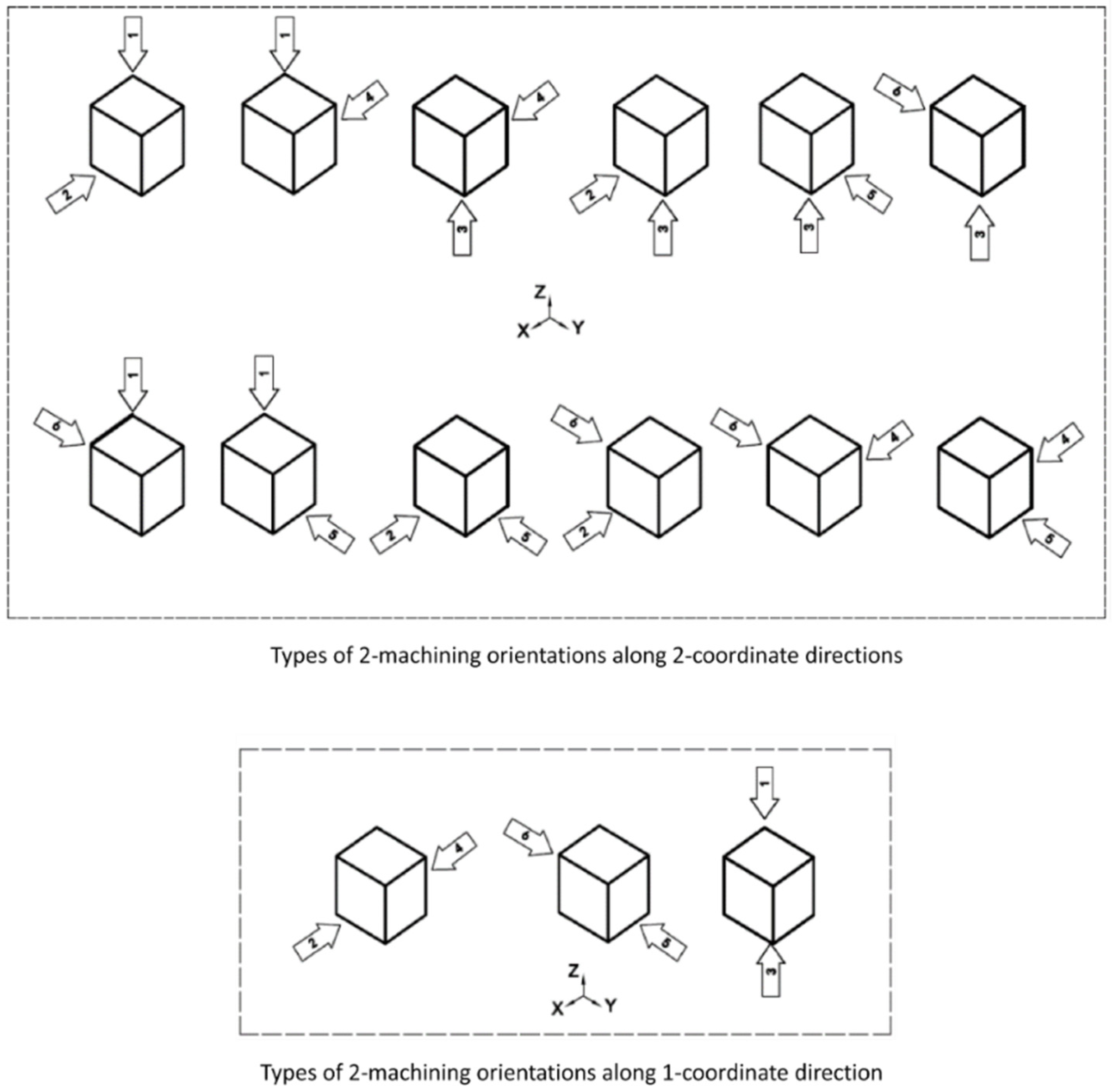
As shown in Figure 11, when the part is machined in 2 parallel machining orientations, there are 2 major categories corresponding to 15 types of parallel machining orientation combinations, which contain 12 types of 2-machining orientations along 2-coordinate directions and 3 types of 2-machining orientations along a 1-coordinate direction.
By analogy, all kinds of parallel machining orientation combinations can be determined. It should be pointed out that the types of parallel machining orientation combinations belonging to one major category can be adjusted to one type by adjusting the orientation of the workpiece through the workpiece turnover device or rotary table.
For the similarity evaluation of the processing types of the processing units corresponding to the two processing segments, because of a great machining difference between the processing segment containing planar machining features and that containing hole machining features, their similarity coefficient is set to 0, and in other cases, their similarity coefficient Sn is set to 1.
Finally, the similarity coefficient S1,2 between processing segment 1 and processing segment 2 can be calculated by Equation (4), and it must be stated that the similarity coefficient S1,2 corresponds to the processing conversion from processing segment 1 to processing segment 2:
4.2. Similarity Evaluation of Processing Plans of the Parts
In general, a processing plan of a part consists of several processing segments, which are arranged in order of processing, and the RMTs corresponding to the processing segments are also arranged in the same order. Therefore, the similarity of two processing plans corresponding to two parts should consider not only the similarity of the processing segments contained in them, but also the similarity of the processing sequence corresponding to the similar processing segments among them.
For example, a processing plan P of part 1 in a part family is as follows:
Another processing plan Q of part 2 in the part family is as follows:
Because the similarity of the two processing plans is comprehensively evaluated by comparing the similarity of the processing segments contained therein, their similarity coefficient must be calculated according to the processing conversion from the processing plan containing more processing segments to that containing fewer processing segments. In this way, the number of comparisons of the processing segments are minimized, and the similarity coefficient of the two processing plans can be quickly obtained.
Using m, n to represent two values, respectively, processing plan P of part 1 includes m processing segments, which are represented by P1~Pm. Processing plan Q of part 2 includes n processing segments, which are represented by Q1~Qn. If m < n, the similarity coefficient SQP of processing plan Q and processing plan P can be calculated by Equation (5), and the similarity coefficient corresponds to the processing conversion from processing plan Q to processing plan P:
where Si is the similarity coefficient of the ith processing segment of processing plan P and its corresponding processing segment of processing plan Q, Ni is the number of the processing units contained in the ith processing segment of processing plan P, and N is the total number of the processing units contained in processing plan P.
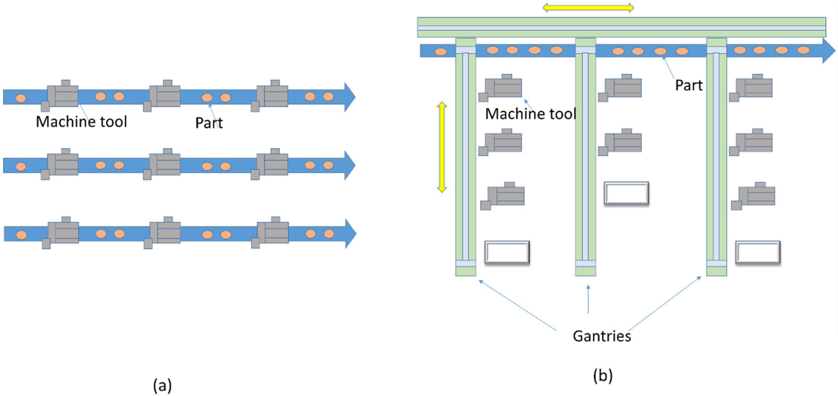
The configuration that consists of several serial lines arranged in parallel (SLP) and the RMS configuration are shown in Figure 12 [3]. The principal difference between the SLP and RMS configurations is that RMS has crossover connections that enable operating several machines in each processing segment in a parallel mode. In practice, a gantry that operates in each processing segment enables these connections. The machine tool is considered a processing module in the RMS configuration. RMTs corresponding to various processing segments can be reconstructed, exchanged, moved, or increased according to the demands of production changes and capacity, and workpieces are transported through the gantry between the machine tools. Obviously, the workpiece can be moved relatively easily and freely between three adjacent machine tools, which correspond to three adjacent processing segments in order of processing. Next, the similarity coefficient Si in Equation (5) can be calculated by Equation (6):
where Si,i−1 are the similarity coefficients of the ith and i−1th processing segments contained in processing plans P and Q, respectively. Similarly, Si,i and Si,i+1 are the other two similarity coefficients.
If processing plans P and Q contain the same number of processing segments, i.e., m = n, the similarity coefficient SQP corresponding to the processing conversion from processing plan Q to P and the similarity coefficient SPQ corresponding to the processing conversion from processing plan P to Q must be calculated, respectively. Finally, the similarity coefficient S between the two processing plans is calculated by Equation (7):
If the most similar processing plans of two parts in a given part family are used for the design of RMTs, it can greatly facilitate rapid processing conversion from one part to another.
5. Validation
5.1. Process Planning of a Given Part Family
Taking the production of a gearbox part family consisting of three parts as an example, as shown in Figure 13, the proposed method was used to create reconfigurable manufacturing processing plans for their processing. In order to improve the processing efficiency, in this application example, RMTs were equipped with as many multi-spindle heads as possible. The machining orientations of each part were represented by numbers 1 to 6 (shown in Figure 13). The steps to create reconfigurable manufacturing processing plans for the processing of the part family were as follows:
- (1)
- The processing information tables of the three parts were created firstly. For example, the processing information for part 1 is shown in Table 2; due to the large amount of information, some processing information is omitted;
- (2)
- For each part, by means of retrieval, those processing features that had the same processing type, locating datums, and machining orientation and could be processed using one multi-spindle head were combined to form natural combination process units;
- (3)
- According to the five combination principles mentioned above, the natural combination process units were combined to form various processing units in each machining orientation of the parts. Next, for each part, a group of processing units could be screened out as a processing unit scheme. There were 27, 23, and 21 processing units in the three processing unit schemes obtained corresponding to part 1, part 2, and part 3, respectively. For example, the processing unit scheme of part 1 is listed in Table 3. Next, for each part, the processing sequence relation matrix of all of the processing units could be created by analyzing their processing sequence information;
- (4)
- For the processing unit scheme of a part, based on the three principles of combining the processing units into a processing segment, the processing segments could be created through the combinations of its processing units. Through the arrangement of the processing segments and the following test using the processing sequence relation matrix of all the processing units, a variety of processing plans of the part could be obtained;
- (5)
- Firstly, the similarity coefficients between all the processing plans corresponding to any two parts in the part family were calculated. Through the comparison and analysis of the similarity coefficients of the processing plans of the three parts, three processing plans corresponding to the three parts with the largest similarity coefficient could be obtained as follows:
The processing plan of part 1 consisted of 13 processing segments and was expressed as follows:
(1)-(2)-(3)-(4,5,6)-(7)-(9,10,11)-(12,15,21)-(13,16,23)-(14,17,25)-(22,8)-(18,26)-(19,27)-(20,24).
The processing plan of part 2 consisted of 12 processing segments and was expressed as follows:
(1)-(4)-(5)-(2,3,6)-(7)-(9,10,11)-(18,12,15)-(13,16,19)-(14,17,20)-(8,21)-(22)-(23).
The processing plan of part 3 consisted of 11 processing segments and was expressed as follows:
(1)-(2)-(3)-(4,5)-(6)-(10,11)-(7,12,17)-(8,14,18)-(9,15,19)-(13,20)-(16,21).
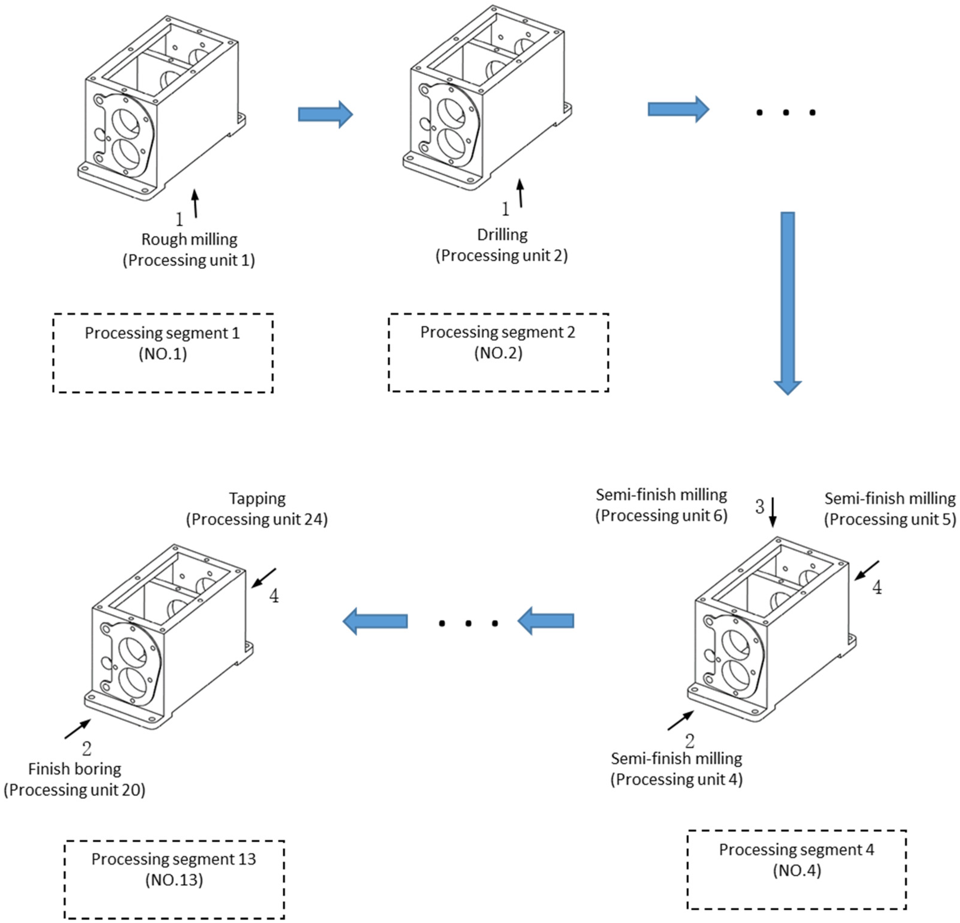
In the above three processing plans, the symbol “-” is the delimiter between two adjacent processing segments. Processing units are indicated by numbers, and the numbers in the parentheses indicate a set of processing units that belong to one processing segment. The processing segments of each processing plan are arranged in the order of processing. The processing information of the three parts’ processing plan is shown in Table 4, and the schematic diagram of the processing information of the processing segments in the plan of part 1 is shown in Figure 14. RMTs should be designed according to the three processing plans of the three parts, and the designed RMTs can be reconstructed and adjusted rapidly to realize the processing conversion of the three parts.
5.2. Design of Reconfigurable Machine Tools
Based on the processing plan of a part, RMT motion schemes that met the processing requirements of all the processing units contained in each processing segment were first created. Autonomous functional modules are autonomous and independently workable [2]. Autonomous functional modules that meet the motion requirements of RMTs can be created by the predefined RMT module groups, which can be obtained by the modular setting of reconfigurable machine tools based on the generative design method [28].
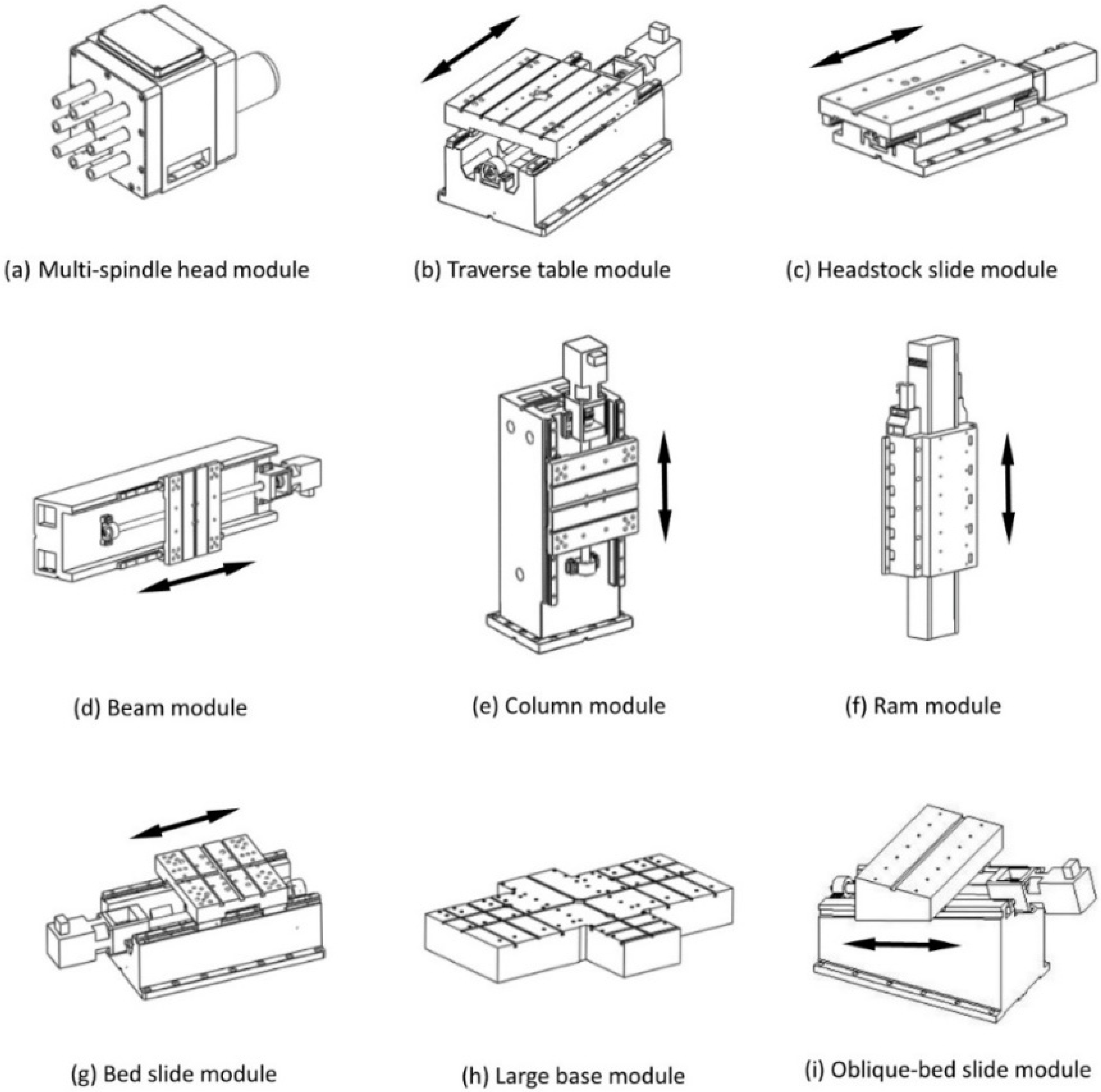
For the production of the above gearbox family, some of the autonomous functional modules obtained were as shown in Figure 15. Next, according to the motion requirements of an RMT, through the selection and connection of these modules, the RMT structural configurations corresponding to each processing segment could be generated.
According to the RMT configurations obtained and the workspace range of the RMTs for the production of the parts in the part family, groups of RMT modules with sizes and detailed structures could be designed. Therefore, RMT modules are dedicated modules that can meet the production demand of a specific part family.
In order to create RMT structural configurations conveniently, the coordinate system of the RMT was established as same as that of the parts shown in Figure 13. RMT motion schemes should be generated to achieve machining operations corresponding to the processing segments of a parts’ processing plan.
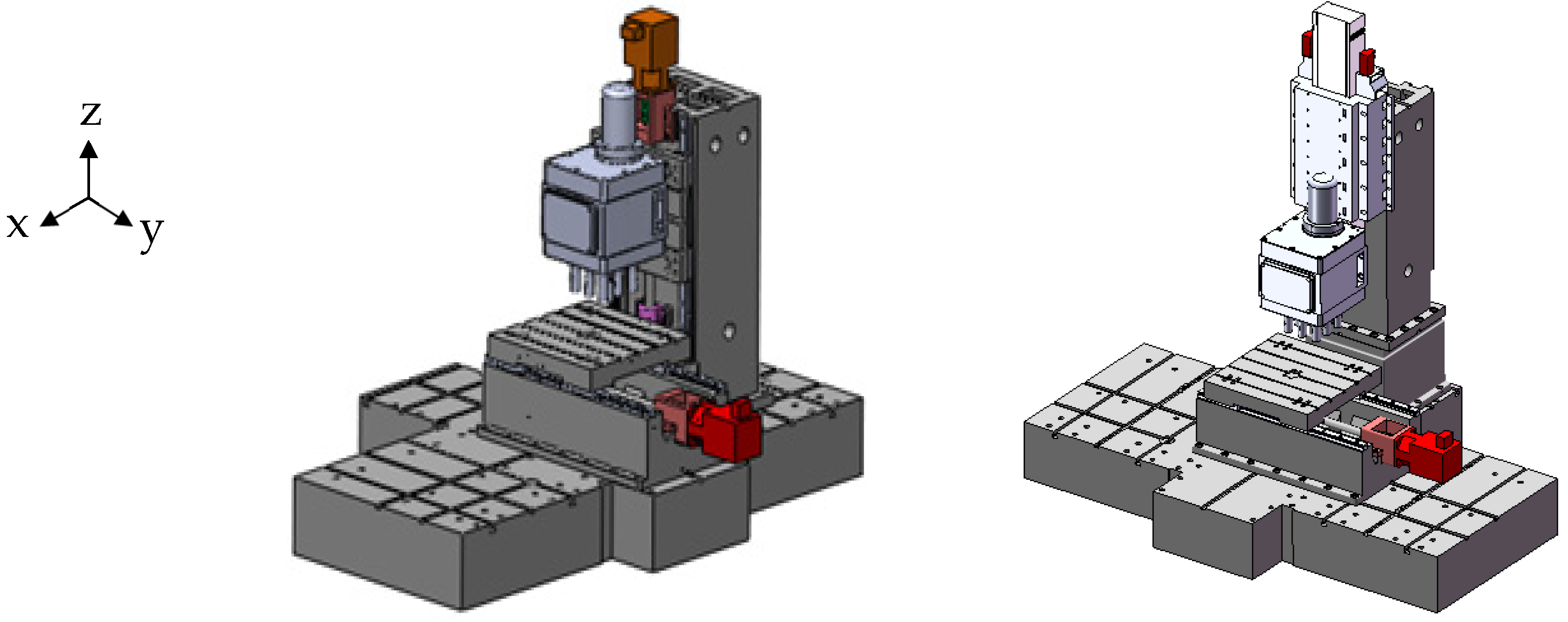
Taking the second processing segment of the processing plan of part 1 as an example, if multi-spindle heads were used for machining, several RMT motion schemes could be generated for the RMT design. This processing segment contained only one processing unit, which corresponded to hole drilling in machining orientation 1 along the Z axis shown in Figure 16. The motion requirements of the RMT can be expressed as T/ZY/W, where Z, Y represent the linear motion degrees of freedom along the Z axis and Y axis, W represents the workpiece, and T represents the tool. The position of the machine base is indicated by inserting the symbol “·” between the T side and the W side of the RMT. According to the selection of the possible positions of the machine base, several RMT motion-schemes could be generated. One of the motion-schemes was T/Z·Y/W, as an example to introduce the construction process of the corresponding RMTs.
For the construction of the machine structures of the T side, the spindle head should be selected firstly as the head-end module. In this case, a multi-spindle head module was selected, as shown in Figure 15a. Next, the module of the Z-direction motion was designed in sequence. A lot of autonomous functional modules of Z-direction motion were generated by the combinations of various RMT modules. Two of them were selected, as shown in Figure 15e,f. For the construction of the machine structures of the W side, the autonomous functional module, which had the function of feeding and withdrawing the workpiece along the Y axis, was needed. One autonomous functional module was selected, as shown in Figure 15b. There were some holes and slots machined on the interface of the RMT modules, which were used to locate and connect the modules during assembly. The large base module shown in Figure 15h was selected as the ground connection module of the RMT. Several guide keyways and connection holes machined on the upper surface of the large base module are used to locate and connect the upper modules mounted on it. Therefore, the modules of the T side and the W side mounted on the large base module could be moved along the guide keyway in directions X and Y. The autonomous functional modules obtained above were connected by fixed mechanical interfaces that aimed to achieve a rapid reconstruction of RMTs. Finally, two RMTs designed by the above configurations are shown in Figure 16.
Obviously, because there may be various autonomous functional modules that can be applied to meet the motion requirements of an RMT, a variety of viable RMT configurations can be generated. Therefore, the obtained RMT configurations can form an abundant RMT configuration library from which the best RMT can be selected to use according to the actual processing conditions.
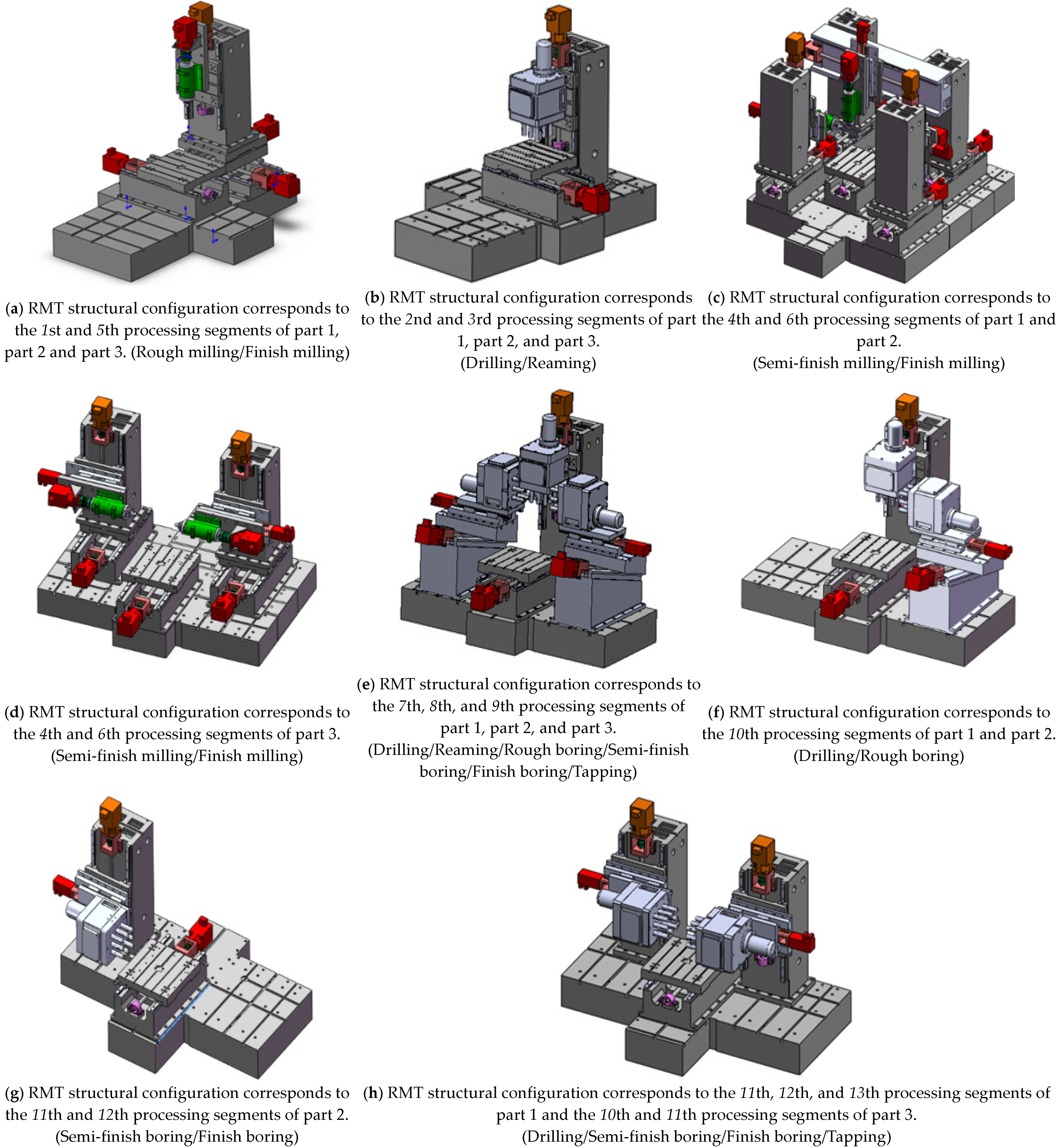
As shown in Figure 17, several RMT configuration schemes were taken as cases, which were generated by the above three processing plans corresponding to part 1, part 2, and part 3, respectively.
As shown in Table 5, RMTs generated by the three processing plans corresponding to part 1, part 2, and part 3, respectively were arranged according to processing sequence, and each RMT corresponded to the processing segment of the part processing plan in order of processing. Processing conversion between RMTs corresponding to the three parts is represented by symbols. The meanings of the processing conversion symbols are as follows.
○: An RMT could be reused to perform all the machining operations of other RMTs;
Δ: Conversion from one RMT to another RMT required replacing the multi-spindle heads;
▼: Conversion from one RMT to another RMT required the operation of adding the workpiece turnover devices to adjust the orientation of the workpiece;
□: Conversion from one RMT to another RMT required the operation of adding the processing components to one machining orientation.
In Table 5, because RMTs enclosed by rectangular dashed frames required the least reconfiguration during processing conversion between the parts within the part family, these RMTs could be used as a preferred design solution for the production of the part family.
Obviously, in this example, the designed RMTs could achieve rapid processing conversion with a small amount of module replacement or adjustment for the production of the given part family of three parts. It shows that RMTs designed by the proposed method based on process planning have significant advantages over existing dedicated machine tools and computerized, numeric-controlled tools in the mass production of part families.
6. Conclusions
At present, for reconfigurable manufacturing (RM), there is still a lack of breakthrough research on key technologies such as reconfigurable process planning, RMT design methods, and RMT module classification, which is also a key problem that hinders the practical application of RM.
An RMS is designed for the production of a given part family and only has production flexibility within the specific part family. Therefore, the process planning of processed parts for reconfigurable manufacturing is completely different from their traditional process planning. It is necessary to carry out parallel process planning of each part in the part family and also consider the tight relationship between reconfigurable manufacturing process planning and RMS construction. RMTs are the core facilities of RMSs, and the structural design of an RMT is the fundamental step in the implementation of an RMS. The idea of designing RMTs closely related to the process planning of a given part family was proposed, an important key technology for realizing the practical application of RMTs and RMSs.
Box-type parts have complex shapes and many machining features, and the processing of box-type parts is also complicated, so this kind of part is a typical representative of complex machining parts. Therefore, through research on the processing characteristics of box-type parts such as their multi-machining orientations and multi-processing types, the mapping relationship between the processing plan and RMT design was established, and a RMT design method for the processing of box-type part families based on parallel process planning of the part families was proposed. This also has important reference value for other types of part family processing.
In order to realize the programmed operation of creating reconfigurable manufacturing processing plans, the method for creating the processing information table of a part was given first, and accordingly, the principles of creating natural combination process units, processing units, and processing segments from processing features were developed. According to the established processing segment schemes, the processing plans of the part could be obtained. Finally, in order to realize rapid processing conversion among the parts in the part family, the similarity comparison model of the processing plans was established, and accordingly, the similarity between the processing plans of two machined parts could be calculated in a quantified form, and the most similar processing plans of the parts could be determined, which served as the basis for the design of RMTs.
According to the processing plans of the machined parts obtained, the machine motion schemes that met the processing requirements of each processing unit in a segment could be generated, and the RMT motion schemes corresponding to each processing segment could be created by the combination of the motions corresponding to all processing units therein. The autonomous functional modules that met the motion requirements of an RMT could be created by the predefined RMT module groups, and through the connection between the modules, RMT structural configurations corresponding to each processing segment could be finally generated.
Because RMTs are designed according to the most similar processing plans of the parts in the part family, they can be quickly reconstructed or adjusted to realize the processing conversion between any two parts. In this way, the goals of high efficiency, low cost, and flexible production for a given part family can be realized.
As mentioned above, because box-type parts have more complicated structures and processing process, the proposed RMT design method for box-type part families can also be roughly applied to the processing of other types of parts families. For example, the structure and processing process of bracket-type parts and box-type parts are generally similar, and the proposed RMT design method can be applied to the processing of such part families. The structures and processing of shafts, sleeves, and plate wheels are relatively simple, but these parts often need to be turned. A special machining orientation can be assigned to the turning features, and the proposed RMT design method can be further improved to obtain the corresponding RMT design method for such parts. In summary, the proposed RMT design method for box-type part families provides a new RMT design idea and useful reference for the processing of various types of part families. In the future, it can be applied to the processing of more types of parts through further expanded research on specific practices.
Author Contributions
Conceptualization, Y.W. and G.Z.; methodology, Y.W. and G.Z.; software, P.L. and Y.W.; validation, Y.W. and G.Z.; formal analysis, Y.W.; investigation, Y.W. and N.W.; resources, Y.W. and J.W.; data curation, J.W. and P.L.; writing—original draft preparation, Y.W. and J.W.; writing—review and editing, J.W. and G.Z.; visualization, P.L. and Y.W.; supervision, G.Z.; project administration, G.Z.; funding acquisition, Y.W. and G.Z. All authors have read and agreed to the published version of the manuscript.
Funding
This research was funded by the National Natural Science Foundation of China, grant number 50875208, and the Scientific & Technological Research Project of the Hubei Provincial Department of Education, grant number D20181803.
Institutional Review Board Statement
Not applicable.
Informed Consent Statement
Not applicable.
Data Availability Statement
Not applicable.
Acknowledgments
The authors would like to gratefully thank the National Natural Science Foundation of China (Grant Nos. 50875208) and the Scientific & Technological Research Project of the Hubei Provincial Department of Education (Grant Nos. D20181803) for the provision of project funding and resources during this research.
Conflicts of Interest
The authors declare no conflict of interest.
References
- Shneor, Y. Reconfigurable machine tool: CNC machine for milling, grinding and polishing. Procedia Manuf. 2018, 21, 221–227. [Google Scholar] [CrossRef]
- Koren, Y.; Heisel, U.; Jovane, F.; Moriwaki, T.; Brussel, H.V. Reconfigurable Manufacturing Systems. CIRP Ann. Manuf. Technol. 1999, 48, 527–540. [Google Scholar] [CrossRef]
- Koren, Y.; Xi, G.U.; Guo, W. Reconfigurable manufacturing systems: Principles, design, and future trends. Front. Mech. Eng. 2018, 13, 121–136. [Google Scholar] [CrossRef] [Green Version]
- Wang, G.; Shang, X.; Yan, Y.; Allen, J.K.; Mistree, F. A tree-based decision method for the configuration design of reconfigurable machine tools. J. Manuf. Syst. 2018, 49, 143–162. [Google Scholar] [CrossRef]
- Koren, Y.; Kota, S. Reconfigurable Machine Tool. U.S. Patent No. 5943750, 31 August 1999. [Google Scholar]
- Koren, Y. General RMS characteristics, comparison with dedicated and flexible systems. In Reconfigurable Manufacturing Systems and Transformable Factories; Springer: New York, NY, USA, 2006; pp. 27–45. [Google Scholar]
- Rösiö, C.; Jackson, M. Enable changeability in manufacturing systems by adopting a life cycle perspective. In Proceedings of the 3rd International Conference on Changeable, Agile, Reconfigurable and Virtual Production, Munich, Germany, 6–9 October 2009; pp. 612–621. [Google Scholar]
- Mehrabi, M.G.; Ulsoy, A.G.; Koren, Y. Reconfigurable manufacturing systems: Key to future manufacturing. J. Intell. Manuf. 2000, 11, 403–419. [Google Scholar] [CrossRef]
- Lee, J.; Bagheri, B.; Kao, H.A. A Cyber-Physical Systems architecture for Industry 4.0- based manufacturing systems. Manuf. Lett. 2015, 3, 18–23. [Google Scholar] [CrossRef]
- Azab, A.; Elmaraghy, H.A. Mathematical modeling for reconfigurable process planning. CIRP Ann. Manuf. Technol. 2007, 56, 467–472. [Google Scholar] [CrossRef]
- Goyal, K.K.; Jain, P.K.; Jain, M. A novel methodology to measure the responsiveness of RMTs in reconfigurable manufacturing system. J. Manuf. Syst. 2013, 32, 724–730. [Google Scholar] [CrossRef]
- Huang, S.; Yan, Y. Design of delayed reconfigurable manufacturing system based on part family grouping and machine selection. J. Prod. Res. 2019, 58, 4471–4488. [Google Scholar] [CrossRef]
- Aguilar, A.; Roman, F.A.; Huegel, J.C. Design, refinement, implementation and prototype testing of a reconfigurable lathe-mill. J. Manuf. Syst. 2013, 32, 364–371. [Google Scholar] [CrossRef]
- Vafadar, A.; Hayward, K.; Tolouei-rad, M. Drilling reconfigurable machine tool selection and process parameters optimization as a function of product demand. J. Manuf. Syst. 2017, 45, 58–69. [Google Scholar] [CrossRef] [Green Version]
- Padayachee, J.; Bright, G. Modular machine tools: Design and barriers to industrial implementation. J. Manuf. Syst. 2012, 31, 92–102. [Google Scholar] [CrossRef]
- Scholz-reiter, B.; Lappe, D.; Grundstein, S. Capacity adjustment based on reconfigurable machine tools-harmonising throughput time in job-shop manufacturing. CIRP Ann. Manuf. Technol. 2015, 64, 403–406. [Google Scholar] [CrossRef]
- Carbonari, L.; Callegari, M.; Palmieri, G.; Palpacelli, M.C. A new class of reconfigurable parallel kinematic machines. Mech. Mach. Theory 2014, 79, 173–183. [Google Scholar] [CrossRef]
- Pérez, R.; Dávila, O.; Molina, A.; Ramírez-Cadena, M. Reconfigurable micro-machine tool design for desktop machining micro-factories. IFAC Proc. Vol. 2013, 46, 1417–1422. [Google Scholar] [CrossRef]
- Bejlegaard, M.; Brunoe, T.D.; Bossen, J.; Andersen, A.L.; Nielsen, K. Reconfigurable Manufacturing potential in small and medium enterprises with low volume and high variety. Procedia CIRP 2016, 51, 32–37. [Google Scholar] [CrossRef] [Green Version]
- Ming, Z.J.; Zeng, C.; Wang, G.X.; Hao, J.; Yan, Y. Ontology-based module selection in the design of reconfigurable machine tools. J. Intell. Manuf. 2020, 31, 301–317. [Google Scholar] [CrossRef]
- Song, Z.Q.; Ding, S.; Chen, Z.W.; Lu, Z.W.; Wang, Z.Z. High-Efficient Calculation Method for Sensitive PDGEs of Five-Axis Reconfigurable Machine Tool. Machines 2021, 9, 84. [Google Scholar] [CrossRef]
- Wang, T.Y.; Sun, X.R.; Tian, S.L.; Zhang, L.; Ma, M.Z. Multi-Objective Optimization Selection Method for the Reconfigurable Machine Tool. J. Tianjin Univ. (Sci. Technol.) 2021, 54, 881–889. [Google Scholar]
- Andersen, A.L.; Brunoe, T.D.; Nielsen, K.; Rosio, C. Towards a generic design method for reconfigurable manufacturing systems: Analysis and synthesis of current design methods and evaluation of supportive tools. J. Manuf. Syst. 2017, 42, 179–195. [Google Scholar] [CrossRef]
- Hees, A.; Bayerl, C.; Vuuren, B.V.; Schutte, C.S.L.; Braunreuther, S.; Reinhart, G. A production planning method to optimally exploit the potential of reconfigurable manufacturing systems. Procedia CIRP 2017, 62, 181–186. [Google Scholar] [CrossRef]
- Kurniadi, K.A.; Ryu, K. Development of IOT-based reconfigurable manufacturing system to solve reconfiguration planning problem. Procedia Manuf. 2017, 11, 965–972. [Google Scholar] [CrossRef]
- Europeans Factories of the Future Research Association. Factories of the Future: Multi-Annual Roadmap for the Contractual PPP under Horizon 2020; Publications Office of the European Union: Brussels, Belgium, 2013. [Google Scholar]
- Uhlmann, E.; Peukert, B. Reconfiguring machine tool behavior via smart building block systems. Procedia Manuf. 2019, 28, 127–134. [Google Scholar] [CrossRef]
- Zhang, G.P.; Wang, L.; Wang, Y.Q.; Hu, X.D. Modular setting of reconfigurable machine tools based on generative design method. China Mech. Eng. 2013, 24, 30–35. [Google Scholar] [CrossRef]
Figure 1.
An automobile gearbox housing with five numbers indicating five machining orientations respectively.
Figure 1.
An automobile gearbox housing with five numbers indicating five machining orientations respectively.

Figure 2.
A part processing plan composed of several processing segments.

Figure 3.
The mapping relationship between a processing segment and its corresponding RMT.

Figure 4.
The general scheme of the design methodology of reconfigurable machine tools.

Figure 5.
An example of extracting the processing information of a part: (a) Obtain all of the final processing features of the part; (b) obtain a homologous processing feature sequence by tracing back from a final processing feature; (c) extract the processing information of processing feature .
Figure 5.
An example of extracting the processing information of a part: (a) Obtain all of the final processing features of the part; (b) obtain a homologous processing feature sequence by tracing back from a final processing feature; (c) extract the processing information of processing feature .


Figure 6.
Schematic diagram of the establishment of the processing information table of the machined part.
Figure 6.
Schematic diagram of the establishment of the processing information table of the machined part.

Figure 7.
Mapping relationship between the part’s processing plan and the reconfigurable manufacturing system.
Figure 7.
Mapping relationship between the part’s processing plan and the reconfigurable manufacturing system.

Figure 8.
The processing units obtained by the combination of the natural combination process units without homologous relationships: (a) Get the first case of multiple processing units (b) Get the second case of multiple processing units (c) Get the third case of multiple processing units (d) Get the fourth case of multiple processing units.

Figure 9.
Flow chart for establishing an alternative processing unit library of a machined part in one machining orientation.
Figure 9.
Flow chart for establishing an alternative processing unit library of a machined part in one machining orientation.

Figure 10.
Two types of parallel machining orientation combinations are represented by A and B, respectively.
Figure 10.
Two types of parallel machining orientation combinations are represented by A and B, respectively.

Figure 11.
Types of parallel machining orientation combinations when a part is machined in two parallel machining orientations.
Figure 11.
Types of parallel machining orientation combinations when a part is machined in two parallel machining orientations.

Figure 12.
Schematic layout of (a) SLP configuration and (b) RMS configuration. Reprinted with permission from ref. [3]. Copyright 2018 Springer.
Figure 12.
Schematic layout of (a) SLP configuration and (b) RMS configuration. Reprinted with permission from ref. [3]. Copyright 2018 Springer.

Figure 13.
A gearbox part family of three parts.

Figure 14.
Schematic diagram of the processing information of the processing segments in the plan for part 1.
Figure 14.
Schematic diagram of the processing information of the processing segments in the plan for part 1.

Figure 15.
Several generated autonomous functional modules.

Figure 16.
Two generated RMTs corresponding to the machining operations of the 2nd processing segment of the processing plan of part 1.
Figure 16.
Two generated RMTs corresponding to the machining operations of the 2nd processing segment of the processing plan of part 1.

Figure 17.
Several RMT structural configurations generated by the obtained three most-similar processing plans corresponding to part 1, part 2, and part 3, respectively.
Figure 17.
Several RMT structural configurations generated by the obtained three most-similar processing plans corresponding to part 1, part 2, and part 3, respectively.


Table 1.
The processing sequence relation matrix of all of the processing units.
| Processing Unit | U1 | U2 | … | Uj | … | Un |
|---|---|---|---|---|---|---|
| U1 | 0 | a12 | … | a1j | … | a1n |
| U2 | a21 | 0 | … | a2j | … | a2n |
| ⋮ | … | … | … | … | … | … |
| Ui | ai1 | ai2 | … | aij | … | ain |
| ⋮ | … | … | … | … | … | … |
| Un | an1 | an2 | … | anj | … | 0 |
Table 2.
Processing information for part 1.
| No. | Orientation | Feature Types | Processing Type | Locating Datum | Coordinate Values (mm) | Hole Diameter | Sequence Label | Homologous Number | Homologous Sequence Number | ||||
|---|---|---|---|---|---|---|---|---|---|---|---|---|---|
| ci,0 | ci,1 | ci,2 | ci,3 | ci,4 | ci,5 | ci,6 | ci,7 | ci,8 | ci,9 | ci,10 | ci,11 | ci,12 | ci,13 |
| 1 | 1 | 1 | 11 | 0 | 0 | 0 | 0 | 0 | 0 | 0 | 0 | 1 | 1 |
| 2 | 1 | 2 | 31 | 1 | 0 | 0 | 183 | −80 | 0 | 13 | 1 | 2 | 1 |
| 3 | 1 | 2 | 31 | 1 | 0 | 0 | −183 | 80 | 0 | 13 | 1 | 3 | 1 |
| 4 | 1 | 2 | 33 | 1 | 0 | 0 | 183 | −80 | 0 | 13 | 2 | 2 | 2 |
| … | … | … | … | … | … | … | … | … | … | … | … | … | … |
| 93 | 4 | 2 | 23 | 4 | 5 | 9 | −163 | −15 | 155 | 72 | 91 | 35 | 2 |
| 94 | 4 | 2 | 23 | 4 | 5 | 9 | −163 | −15 | 77 | 72 | 92 | 36 | 2 |
Table 3.
Processing units of part 1.
| No. | Orientation | Locating Datums | Sequence Label | Processing Features | Notes |
|---|---|---|---|---|---|
| 1 | 1 | 0, 0, 0 | 0 | 1 | Rough milling |
| 2 | 1 | 1, 0, 0 | 1 | 2, 3 | Drilling |
| 3 | 1 | 1, 0, 0 | 2, 3 | 4, 5 | Reaming |
| 4 | 2 | 1, 4, 5 | 5 | 6 | Semi-finish milling |
| 5 | 4 | 1, 4, 5 | 5 | 7 | Semi-finish milling |
| 6 | 3 | 1, 4, 5 | 5 | 8 | Semi-finish milling |
| 7 | 1 | 6, 7, 8 | 8 | 9 | Finish milling |
| 8 | 1 | 4, 5, 9 | 9 | 10, 11 | Drilling |
| 9 | 2 | 4, 5, 9 | 9 | 12 | Finish milling |
| 10 | 4 | 4, 5, 9 | 9 | 13 | Finish milling |
| 11 | 3 | 4, 5, 9 | 9 | 14 | Finish milling |
| 12 | 2 | 4, 5, 9 | 12 | 15-21 | Drilling |
| 13 | 2 | 4, 5, 9 | 15–21 | 22–28 | Reaming |
| … | … | … | … | … | … |
| 26 | 4 | 4, 5, 9 | 13, 74 | 91, 82 | Semi-finish boring/Reaming |
| 27 | 4 | 4, 5, 9 | 13 | 92 | Semi-finish boring |
Table 4.
Comparison of the processing information of the three parts’ processing plans.
| Processing plan of part 1 | Number of each processing segment | 1 | 2 | 3 | 4 | 5 | 6 | 7 | 8 | 9 | 10 | 11 | 12 | 13 |
| The numbers corresponding to processing units in each processing segment | 1 | 2 | 3 | 4, 5, 6 | 7 | 9, 10, 11 | 12, 15, 21 | 13, 16, 23 | 14, 17, 25 | 22, 8 | 18, 26 | 19, 27 | 20, 24 | |
| Machining operations of each processing segment | Rough milling | Drilling | Reaming | Semi-finish milling | Finish milling | Finish milling | Drilling | Reaming | Finish boring/Reaming | Drilling | Semi-finish boring | Semi-finish boring | Finish boring/Tapping | |
| Corresponding machining orientations | 1 | 1 | 1 | 2, 4, 3 | 1 | 2, 4, 3 | 2, 3, 4 | 2, 3, 4 | 2, 3, 4 | 1, 4 | 2, 4 | 2, 4 | 2, 4 | |
| Processing plan of part 2 | Number of each processing segment | 1 | 2 | 3 | 4 | 5 | 6 | 7 | 8 | 9 | 10 | 11 | 12 | |
| The numbers corresponding to processing units in each processing segment | 1 | 4 | 5 | 2, 3, 6 | 7 | 9, 10, 11 | 18, 12, 15 | 13, 16, 19 | 14, 17, 20 | 8, 21 | 22 | 23 | ||
| Machining operations of each processing segment | Rough milling | Drilling | Reaming | Semi-finish milling | Finish milling | Finish milling | Drilling/Rough boring | Reaming/Semi-finish boring | Finish boring/Tapping | Drilling/Rough boring | Semi-finish boring | Finish boring | ||
| Corresponding machining orientations | 1 | 1 | 1 | 2, 4, 3 | 1 | 2, 4, 3 | 2, 3, 4 | 2, 3, 4 | 2, 3, 4 | 1, 2 | 2 | 2 | ||
| Processing plan of part 3 | Number of each processing segment | 1 | 2 | 3 | 4 | 5 | 6 | 7 | 8 | 9 | 10 | 11 | ||
| The numbers corresponding to processing units in each processing segment | 1 | 2 | 3 | 4, 5 | 6 | 10, 11 | 7, 12, 17 | 8, 14, 18 | 9, 15, 19 | 13, 20 | 16, 21 | |||
| Machining operations of each processing segment | Rough milling | Drilling | Reaming | Semi-finish milling | Finish milling | Finish milling | Drilling | Reaming | Tapping | Drilling/Semi-finish boring | Finish boring | |||
| Corresponding machining orientations | 1 | 1 | 1 | 2, 4 | 1 | 2, 4 | 1, 2, 4 | 1, 2, 4 | 1, 2, 4 | 2, 4 | 2, 4 |
Table 5.
Processing conversion of RMTs generated by the three processing plans corresponding to part 1, part 2, and part 3, respectively.
Table 5.
Processing conversion of RMTs generated by the three processing plans corresponding to part 1, part 2, and part 3, respectively.

Publisher’s Note: MDPI stays neutral with regard to jurisdictional claims in published maps and institutional affiliations. |
© 2021 by the authors. Licensee MDPI, Basel, Switzerland. This article is an open access article distributed under the terms and conditions of the Creative Commons Attribution (CC BY) license (https://creativecommons.org/licenses/by/4.0/).
Share and Cite
MDPI and ACS Style
Wang, Y.; Zhang, G.; Wang, J.; Liu, P.; Wang, N. Reconfigurable Machine Tool Design for Box-Type Part Families. Machines 2021, 9, 148. https://0-doi-org.brum.beds.ac.uk/10.3390/machines9080148
AMA Style
Wang Y, Zhang G, Wang J, Liu P, Wang N. Reconfigurable Machine Tool Design for Box-Type Part Families. Machines. 2021; 9(8):148. https://0-doi-org.brum.beds.ac.uk/10.3390/machines9080148
Chicago/Turabian StyleWang, Yongquan, Guangpeng Zhang, Jiali Wang, Pan Liu, and Nina Wang. 2021. "Reconfigurable Machine Tool Design for Box-Type Part Families" Machines 9, no. 8: 148. https://0-doi-org.brum.beds.ac.uk/10.3390/machines9080148
Note that from the first issue of 2016, this journal uses article numbers instead of page numbers. See further details here.