
Numerical Computation and Analysis of Electromagnetic Field in Magnetic Suspension and Balance System

College of Intelligence Science and Technology, National University of Defense Technology, Changsha 410073, China
*
Author to whom correspondence should be addressed.
Magnetochemistry 2021, 7(3), 33; https://0-doi-org.brum.beds.ac.uk/10.3390/magnetochemistry7030033
Submission received: 30 December 2020
/
Revised: 31 January 2021
/
Accepted: 2 February 2021
/
Published: 26 February 2021
(This article belongs to the Special Issue Advances in Computational Electromagnetics)
Abstract
:The magnetic suspension wind tunnel balance (MSBS) is an entirely new device for aerodynamic measurement, and it makes the best of the electromagnetic force to suspend the aircraft model in the wind tunnel without contact. Compared with conventional wind tunnel balance, it absolutely abandons the model support and airflow interference. Therefore, the aerodynamic measurement environment is more authentic and the aerodynamic measurement results are more accurate. The electromagnetic field in MSBS plays a major role in bearing the force of wind. The numerical computation and finite element numerical analysis are performed to investigate key factors of electromagnetic force under different conditions. The calculation results based on finite element method (FEM) have revealed that the diameter and the spacing of of the axial coil, the number of segments and the pitch angle of the suspension model are key factors of electromagnetic force. Based on the above key factors, the structure of the magnetic suspension balance is optimized to maximize the electromagnetic force under multiple constraints.
1. Introduction
With the development of the aerospace industry, there is more and more demand for high subsonic aircraft, and its aerodynamic test problem attracts more and more attention. The aircraft is prone to dynamic instability in a high subsonic state [1]. Therefore, it is necessary to further study the aerodynamic characteristics of the atmospheric reentry module of the spacecraft in a high subsonic state through a high subsonic wind tunnel test [2,3]. In general wind tunnel test, the model of the tested vehicle is supported by the support [4,5], and the aerodynamic test is carried out through the strain balance [6,7] connected with the support. In most wind tunnel tests, especially in forced vibration wind tunnel tests, the support mechanism will vibrate with the model [8,9], which will increase the interference of the support mechanism in the flow field. In addition, the existence of the model support seriously interferes with the real flow field of the wind tunnel, resulting in the distortion of the flow field around the model, which makes the wind tunnel aerodynamic test results deviate from the actual value, affects the accuracy of the model aerodynamic test data, and limits the range of translation and rotation of the model. For the dynamic test, the amplitude and frequency are greatly limited, which limits the ability of the wind tunnel test [10,11].
In order to solve this problem, the experimental device of unsupported wind tunnel has been studied all over the world. The support of the suspension model completely depends on electromagnetic force, and its stiffness is affected by the control system. The control system can make the tested model suspend stably through feedback control. Suspension train is a good application example which is feasible. In 2017, the National Aeronautics and Space Administration (NASA) green research center carried out a feasibility study on the application of MSBS in the 225 cm2 supersonic wind tunnel (5wt) to measure the dynamic derivatives of reentry blunt bodies, and Langley Research Center is also upgrading the MSBS system developed by Massachusetts Institute of Technology(MIT) [12]. The Old Dominion University of the United States is also carrying out the research on the dynamic stability measurement of the re-entry capsule by MSBS, which is planned to be carried out in the 6ft low-speed wind tunnel of NASA Langley Research Center [13,14]. The existing specifications of 0.1 M MSBS developed by Japan in 2019 are as follows: diameter is 100 mm, gas velocity is 0.6 to 0.8 mach, the maximum axial current is 120 A, and maximum axial load force is 2.5 N [15].
The difficulty and emphasis of the magnetic suspension balance without support is the axial force provided by the electromagnetic coil. The factors influencing the axial force of the MSBS are complex and diverse, such as the coil structure, spatial arrangement, and so on. The coil current has a limit value. When the limit value is exceeded, the electromagnet coil is heated seriously. The inner diameter and outer diameter of the coil are restricted by the mechanical structure, which should not be too small and too large at the same time. In order to understand the influence of various factors on the axial force, this paper studies the axial coil of the 0.1 m high subsonic MSBS, establishes an accurate model of the MSBS and combines with the numerical simulation method to study the factors affecting the axial electromagnetic field strength and the electromagnetic force. By optimizing the coil size, structure, and suspension model parameters of MSBS, the axial electromagnetic force load of 0.1 m-high subsonic MSBS is increased.
This paper is organized as follows. In Section 2, the system and mechanical structure of MSBS will be introduced. In Section 3, the simplified model of the axial electromagnetic field of MSBS will be established, the mathematical expression will be deduced, and the three-dimensional simulation model and numerical analysis parameters of the axial electromagnetic system will be set up with electromagnetic analysis software Maxwell. In Section 4, the analysis results will be presented, which factors will affect the axial electromagnetic field, and what is the variation law? In Section 5, we will discuss how to select the optimal parameters, what the optimized parameters are, and what problems exist, and what we need to continue to study later. Finally, the conclusions of this study are given in Section 6.
2. Magnetic Suspension System
2.1. System Compositions
The axial coil current control of magnetic suspension balance is similar to that of NMR, but the working frequency is lower than 1 kHz. Its current is large and its fluctuation range is small, so it can be regarded as a static magnetic field. The working frequency of NMR is higher than 1 MHz [16], the current is small, the fluctuation range is large, it is a mainly dynamic magnetic field.
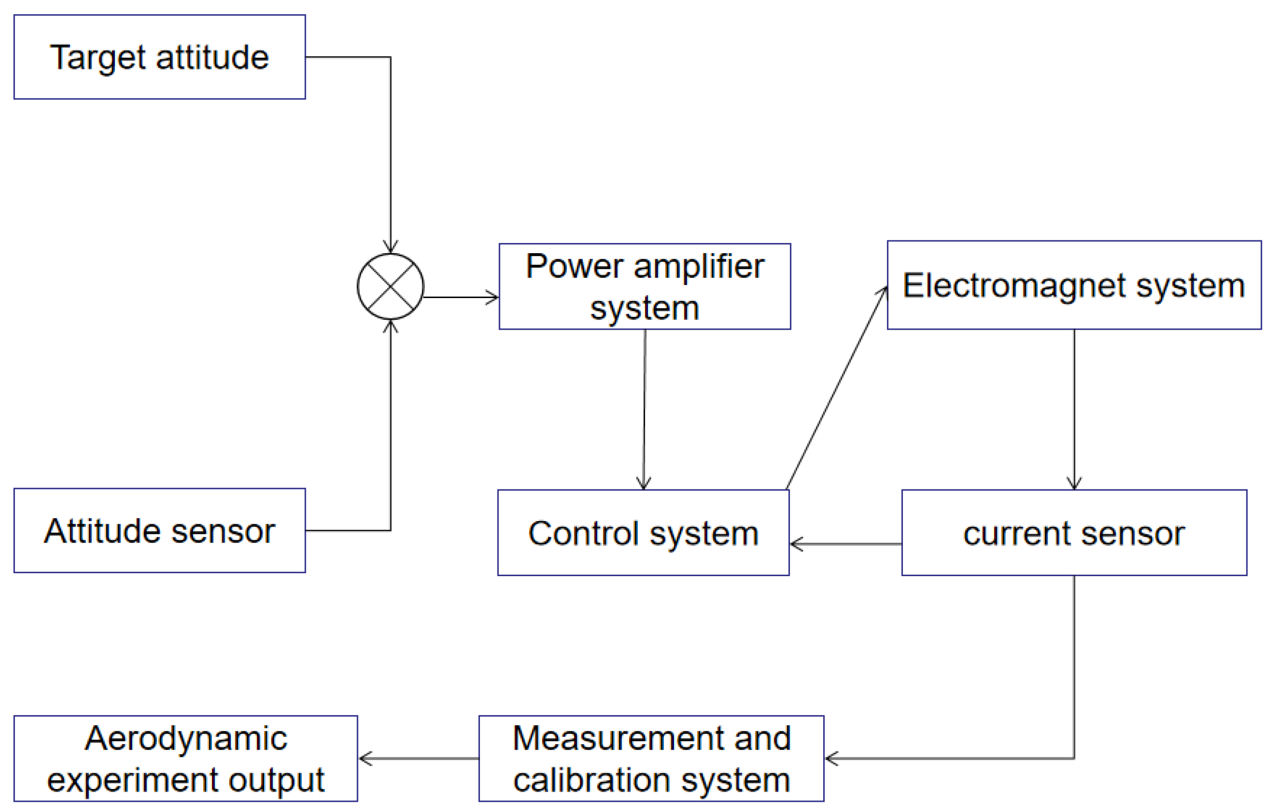
As shown in Figure 1, MSBS is mainly composed of an electromagnetic system, control system and measurement system. In order to realize the suspension of the suspension model, it is necessary to obtain information from the position and attitude measurement sensor and the current sensor as the feedback signal, and then calculate according to the feedback signal, output the control signal to the power amplifier system, and the power amplifier system outputs the corresponding voltage and current to the electromagnet system to generate electricity. The magnetic force is used to balance the gravity and aerodynamic load of the suspended model. The electromagnetic system of MSBS is the most basic and important.
2.2. Mechanical Structure
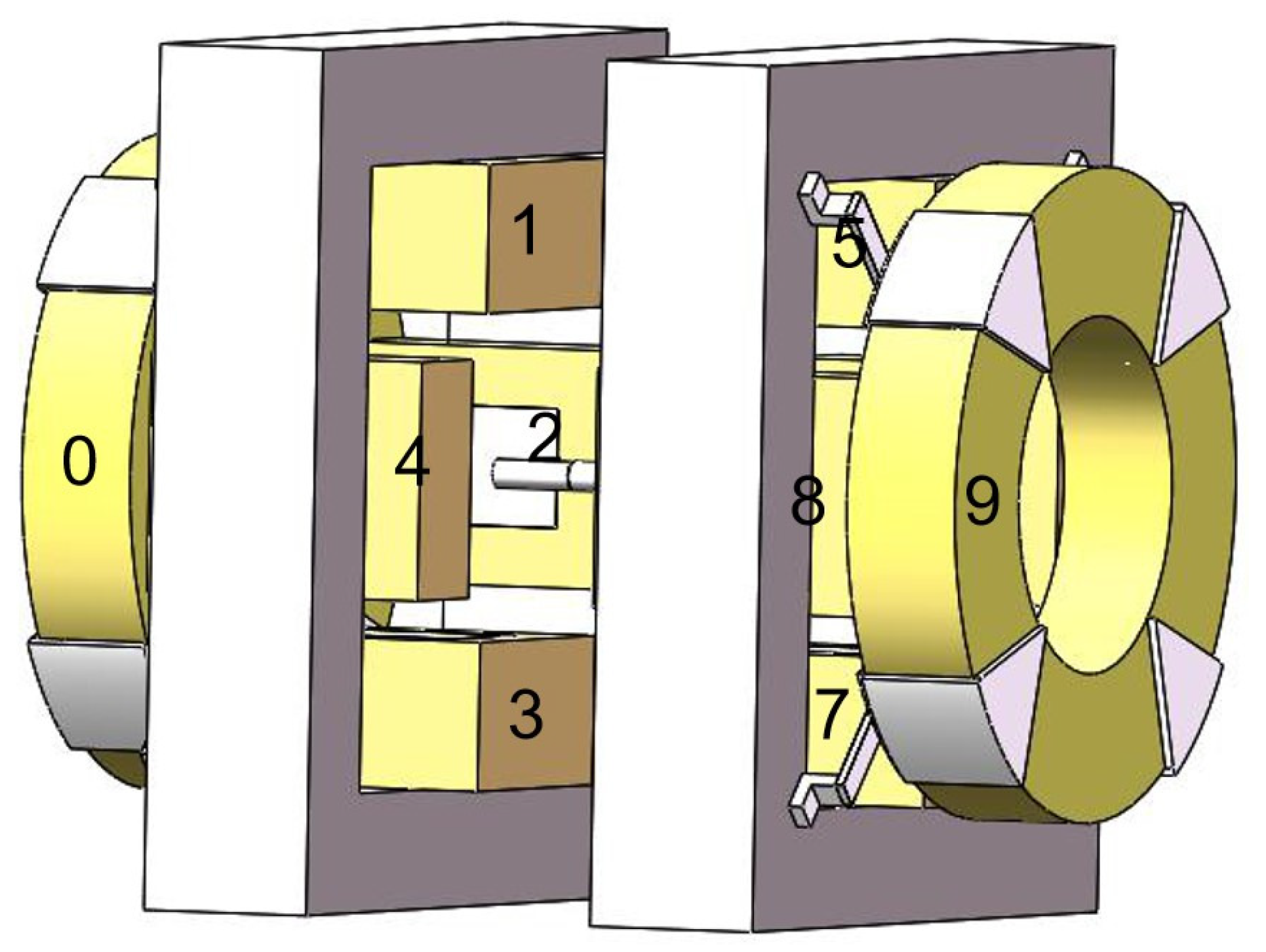
Firstly, by modeling the system, the magnetic structure is designed correctly to ensure the independence of each channel control and reduce the mutual interference. The electromagnetic coil distribution structure as shown in Figure 2 is proposed, and the symmetrical structure of ten electromagnets (two hollow cores and eight iron cores) with five channels is adopted. The displacement in each direction of freedom is regulated and controlled by the corresponding degree of freedom control coil.
As shown in Figure 2, the electromagnetic coils of the magnetic suspension balance are divided into five pairs, one in the axial direction, two in the vertical direction and two in the lateral direction. A pair of vertical coils is distributed in the head and tail of the suspension model, and a pair of lateral coils is also distributed in the head and tail of the suspension model. A permanent magnet electromagnetic suspension structure is adopted, and the suspension model contains a permanent magnet. The displacement adjustment in each direction depends on the repulsion of one coil to the suspension model and the suction of another coil to the suspension model. Coils 0 and 9 are axial coils to control the axial movement of the suspension model. Coils 1, 3, 5 and 7 are vertical coils, which control the up-down and pitch motion. Coils 2, 4, 6 and 8 are lateral coils, which control the movement of left and right and yaw direction. The rolling motion is controlled by the rotating magnetic field superposed by 5, 6, 7 and 8 coils. According to the technology of electromagnet permanent magnet hybrid suspension, the number, size, shape and spatial position arrangement of electromagnet coils and the shape and size of suspension model permanent magnet core are preliminarily designed through magnetic circuit analysis. Then the finite element analysis method is proposed to simulate and analyze the magnetic field and magnetic force. The magnetic field of the permanent magnet can be calculated from the magnetization curve and shape size of the permanent magnet model material. After setting the shape and number of turns of the electromagnet coil, a certain current is applied to the electromagnet coil to initially calculate the magnetic field distribution and electromagnetic force.
3. Electromagnetic Analysis
On the one hand, the electromagnet coil is the actuator, so we need to master the characteristics of the actuator in order to better carry out real-time control. On the other hand, the characteristic curves of current, attitude, and electromagnetic force can be obtained to prepare for the subsequent real-time aerodynamic measurement and calibration.
3.1. Mathematical Model
Because the axial coil is a hollow coil, the size and current of the axial coil are the largest. The axial electromagnetic field simulation analysis is carried out, as shown in Figure 3.
3.2. Simulations
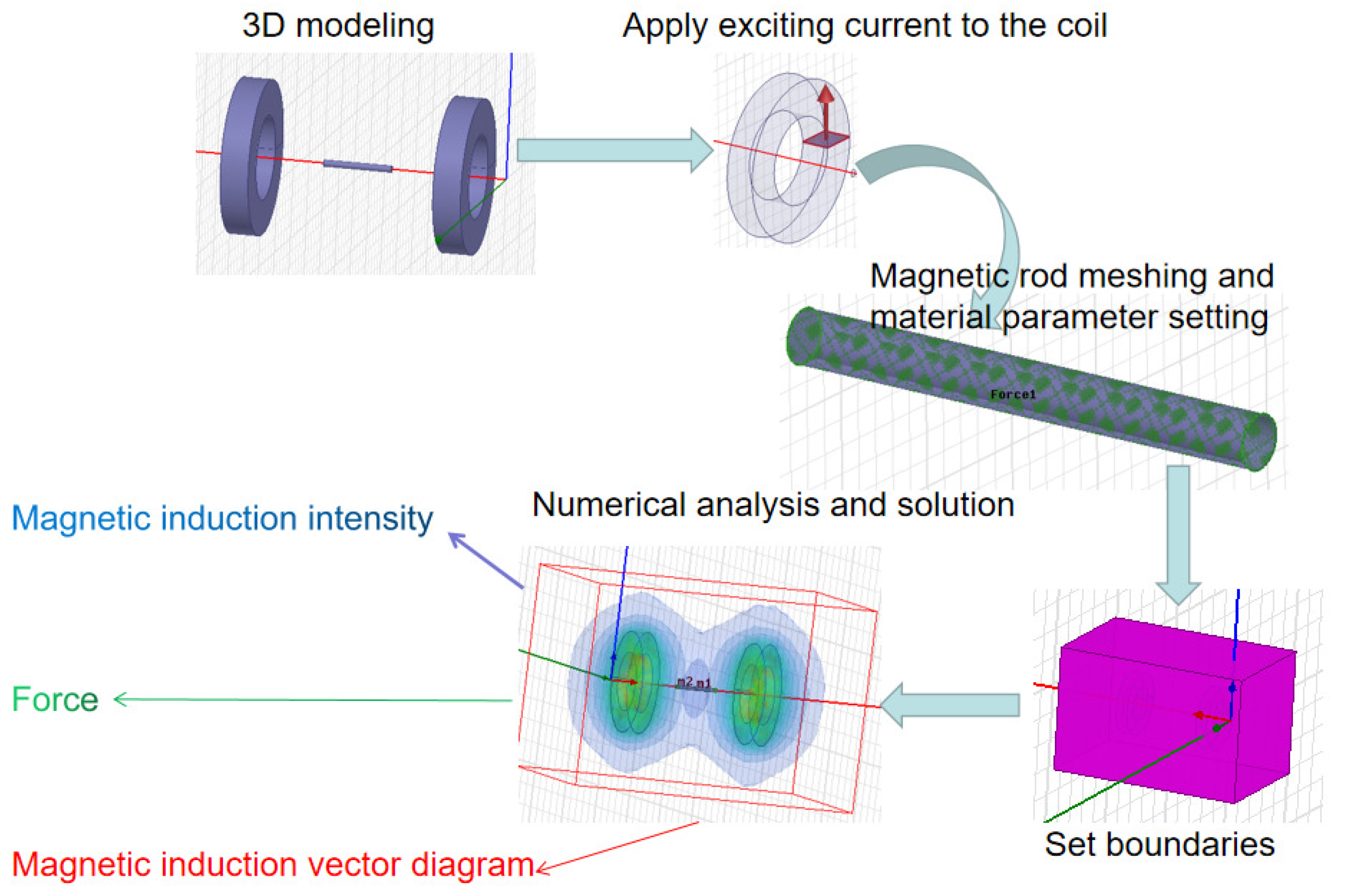
The two-dimensional model can not accurately reflect the magnetic field of the MSBS, and the calculated force is not accurate, so the three-dimensional model is established. When the model is established, the three-dimensional diagram is drawn according to the accurate size of the designed coil, and the accurate ampere-turns are set. For the characteristics of the suspension model magnet, it is more practical to use NdFeB material to set its parameters. This model is more accurate. The simulation calculation flow of MSBS is shown in Figure 4. The electromagnetic field model of magnetic suspension balance is established in the finite element software. The numerical model is calculated by Maxwell. Firstly, the material properties are added. The coil material is copper wire and the magnetic rod material is NdFeB. Then the current cross-section is set and the exciting current is applied to the cross-section. Finally, the solver is set to solve the problem, and the distribution of magnetic field intensity is shown. By changing the model parameters, we can observe the influence of the parameters.
The detailed steps of the finite element simulation method are as follows:
- (1)
- Choosing solution type [20]The MSBS can be regarded as a static magnetic field. Static magnetic field solver is selected as the simulation type in order to solve the problems.
- (2)
- Establishing the 3D modelThe diameter area of the axial electromagnet coil is 16 mm, the shape is oblong, the length is 8 mm, the thickness is 2 mm, and the number of turns of the coil is 125. The length of the middle magnetic rod is 96 mm and the diameter is 10 mm. According to the size parameters of the MSBS, the mathematical coordinates are established, the parameters are input, and the model is established.
- (3)
- Apply exciting current to the coilDraw a section on the axial coil. The section is perpendicular to the inner and outer rings. The area of the section is the coil width multiplied by the difference between the inner and outer rings. The current is increased from 20 A to 100 A, and one data is recorded every 20 A.
- (4)
- Magnetic rod meshing and material parameter settingThe mesh number of the model is 1000 for the middle magnetic rod model, and 10,000 for the coil model because it is larger than the magnetic rod model, which is 10 times of the middle magnetic rod model. The force parameters are set on the suspension model.
- (5)
- Set boundariesAlthough the boundary of the actual physical system is infinite, the electromagnetic field is very small or tends to zero when the distance is far away, so it is necessary to limit the solution area and boundary, and set the shape of the solution area as a square, and the size increases by 50% compared with the size of the original model.
- (6)
- Numerical analysis and solutionThe error tolerance is 1% After each step of the calculation, the calculation matrix is updated.
- (7)
- Results acquisition and analysis.
Different parameters, such as the shape and size of the coil, the distance of the axial coil and the number of segments of the magnetic bar, are changed to obtain different electromagnetic fields and forces, and the results are analyzed and studied.
4. Results
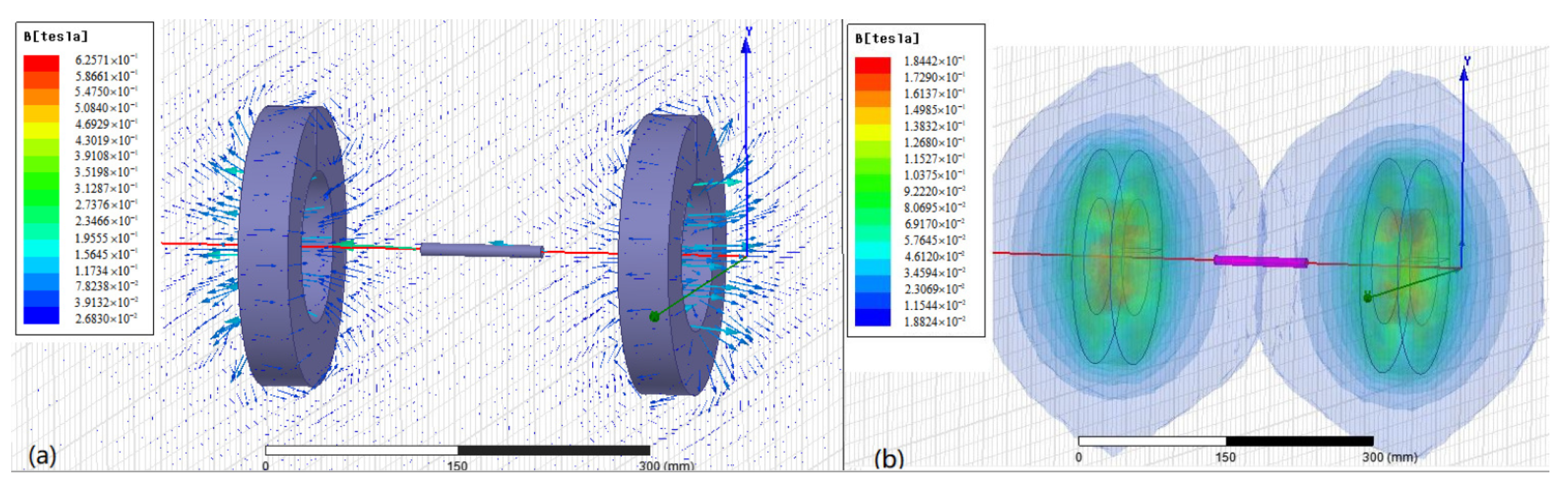
Figure 5a shows the vector diagram and cloud diagram of the axial magnetic induction intensity calculated by the finite element electromagnetic method. It can be seen from the figure that the magnetic fields generated by the front and rear axial coils are in opposite directions, and the magnetic induction lines in the coil center are relatively dense. Figure 5b is the cloud picture of magnetic field intensity. The shape is two oblate spheres. The gradient in the center of the coil is larger, and the gradient in the outer layer of the sphere is smaller.
The influence of different coil diameters on the axial coil is studied under the condition of the same coil turns. Four groups of coil direct structures were studied, including coil inner diameter and coil outer diameter. The parameters of coil shape 1 are: the inner diameter is 100 mm and the outer diameter is 200 mm. The parameters of coil shape 1 are: the inner diameter is 100 mm and the outer diameter is 200 mm. The parameters of coil shape 2 are: inner diameter 120 mm, outer diameter 220 mm. The parameters of coil shape 3 are: inner diameter 140 mm, outer diameter 240 mm. The parameters of coil shape 4 are: inner diameter 160 mm, outer diameter 260 mm. The curve of the simulation experiment is drawn in Figure 6a. It can be seen that the larger the coil diameter, the greater the electromagnetic force. When the coil shape changes from coil shape 1 to coil shape 2, the electromagnetic force increases greatly; when the coil shape 3 changes to the coil shape 4 parameter, the electromagnetic force increases slowly. Figure 6b shows the magnetic induction produced by the axial coil at the end of the magnetic rod, and its variation trend is the same as that of the electromagnetic force.
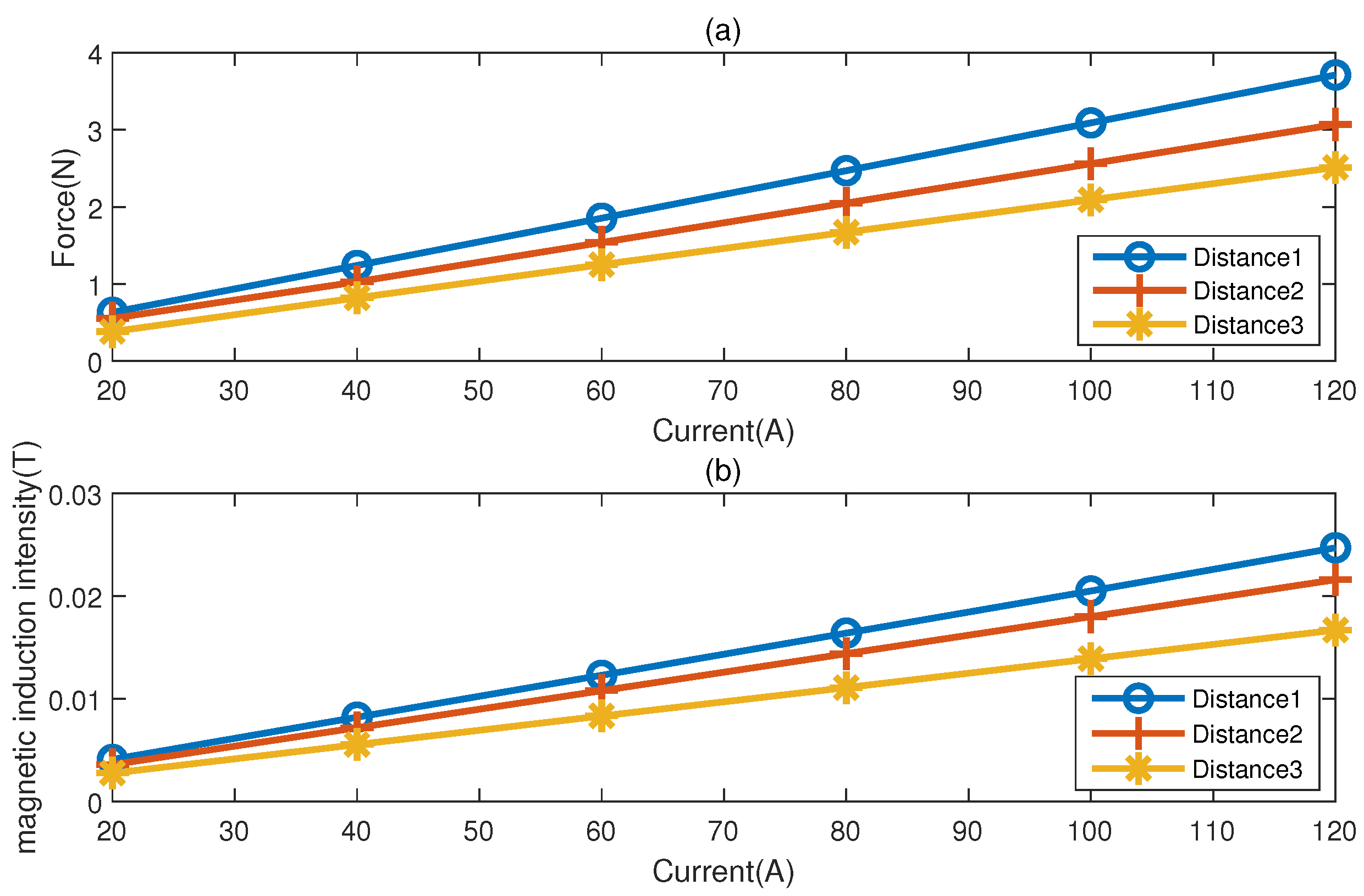
Under the condition that other parameters remain unchanged, the influence of the axial coil spacing on the electromagnetic characteristics of the axial coil is studied by changing the distance between the axial coils. Coil distance 1 represents axial coil distance 244 mm, coil distance 2 represents axial coil distance 264 mm, coil distance 3 represents axial coil distance 284 mm. The results of the simulation experiment are drawn into a curve. It can be seen from Figure 7a that the characteristics of the electromagnetic force current curve are greatly affected by the distance. The farther the distance is, the less the electromagnetic force will be. Figure 7b shows the magnetic induction produced by the axial coil at the end of the magnetic rod, and its variation trend is the same as that of the electromagnetic force.
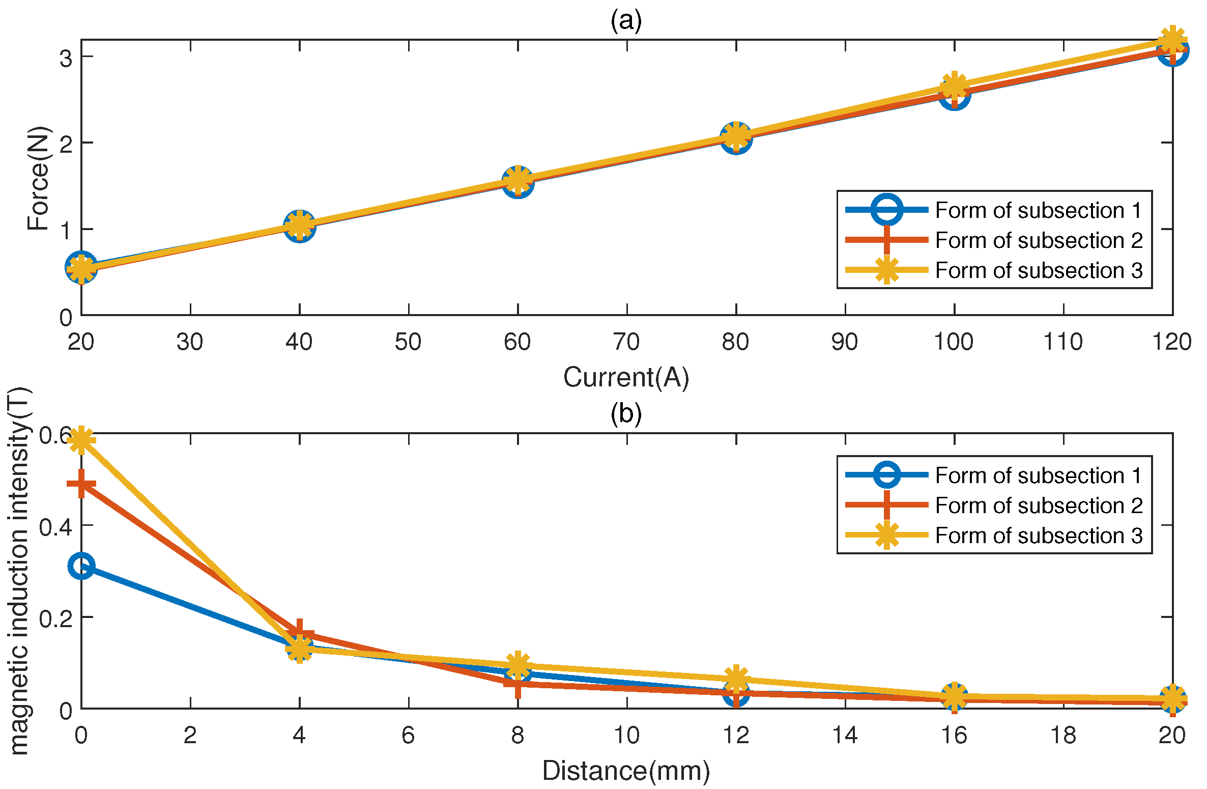
The influence of the number of permanent magnet segments on the axial electromagnetic force is studied by suspending the number of segments of the model magnetic rod while other parameters remain unchanged. The number of segments form 1 represents that the suspension model is a total of 1 segment with a length of 96 mm. The number of segments form 2 represents that the suspension model is 3 segments in total, and the segment length is 32 mm. The number of segments form 3 represents that the suspension model is six segments in total, and the segment length is 16 mm. The results of the simulation experiment are drawn in Figure 8a, which shows that the characteristics of the electromagnetic force current curve are less affected by the number of suspension model segments. The more the number of suspension model segments, the electromagnetic force decreases slowly. The number of magnetic field segments has little effect on the intensity of the magnetic field near the bar, but the intensity of the magnetic field near the bar has little effect on the intensity of the magnetic field near the bar. It can be seen from Figure 8b, that when the distance exceeds 4 mm, there is almost no influence.
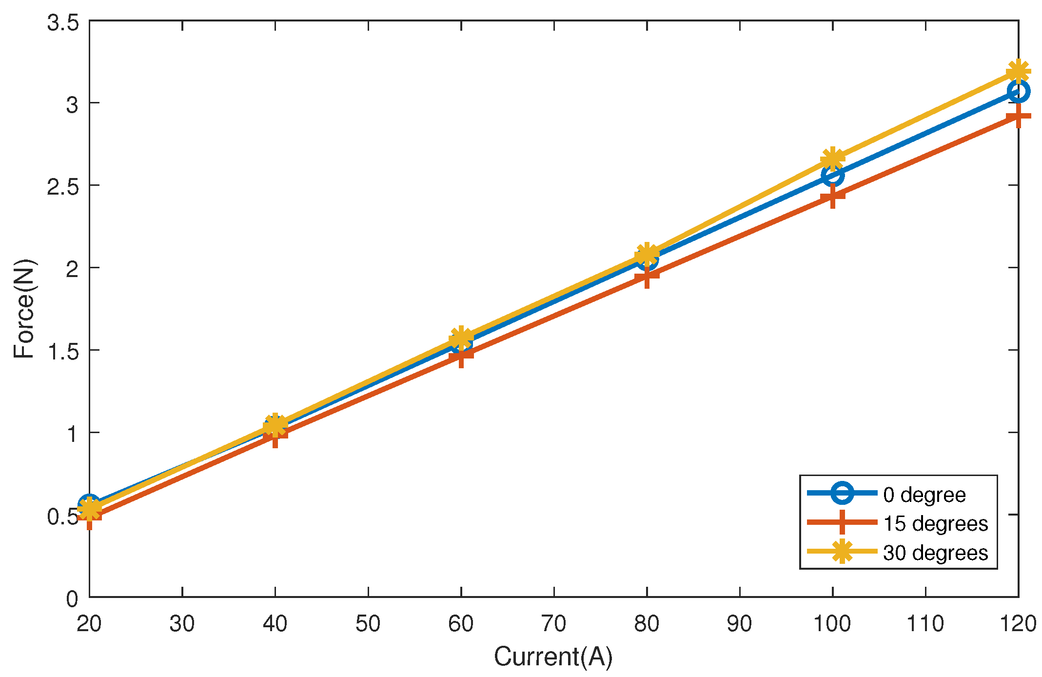
The influence of the angle between the magnetic rod and the horizontal plane on the axial electromagnetic force is studied. The characteristics of electromagnetic force are simulated and analyzed when pitch angles are 0 degrees, 15 degrees and 30 degrees respectively. The results of the simulation experiment are drawn in Figure 9, which shows that the characteristics of the electromagnetic force current curve are affected by the pitch angle of the suspension model. In a certain range which is 0 degrees to 15 degrees, reducing the attached elevation angle of the suspension model can increase the electromagnetic force, but beyond this range, it is not tenable, because the axial electromagnetic field is nonlinear.
5. Discussion
By analyzing the coil size, space layout, suspension model segment number, and pitch angle, the structure of MSBS is optimized. When the inner diameter is 120 mm and the outer diameter is 220 mm, the distance between axial coils is 264 mm, the suspension model segment number is 1, the pitch angle of suspension model is 0 degree, the magnetic force is equal to 2.5 N, the required current is 100 A, while the magnetic suspension balance of the same size needs a current of 120 A in Japan, and reducing the current by 20 A can reduce the power consumption and heating. When the current is 120 A, the axial force is 3.07 N. In this paper, the influence of the pitch angle of the suspension model on the axial force is considered. When the angle is 30 degrees and the current is 120 A, the axial force energy is as high as 2.8 N. The detailed parameters of the axial coil are shown in Table 1.
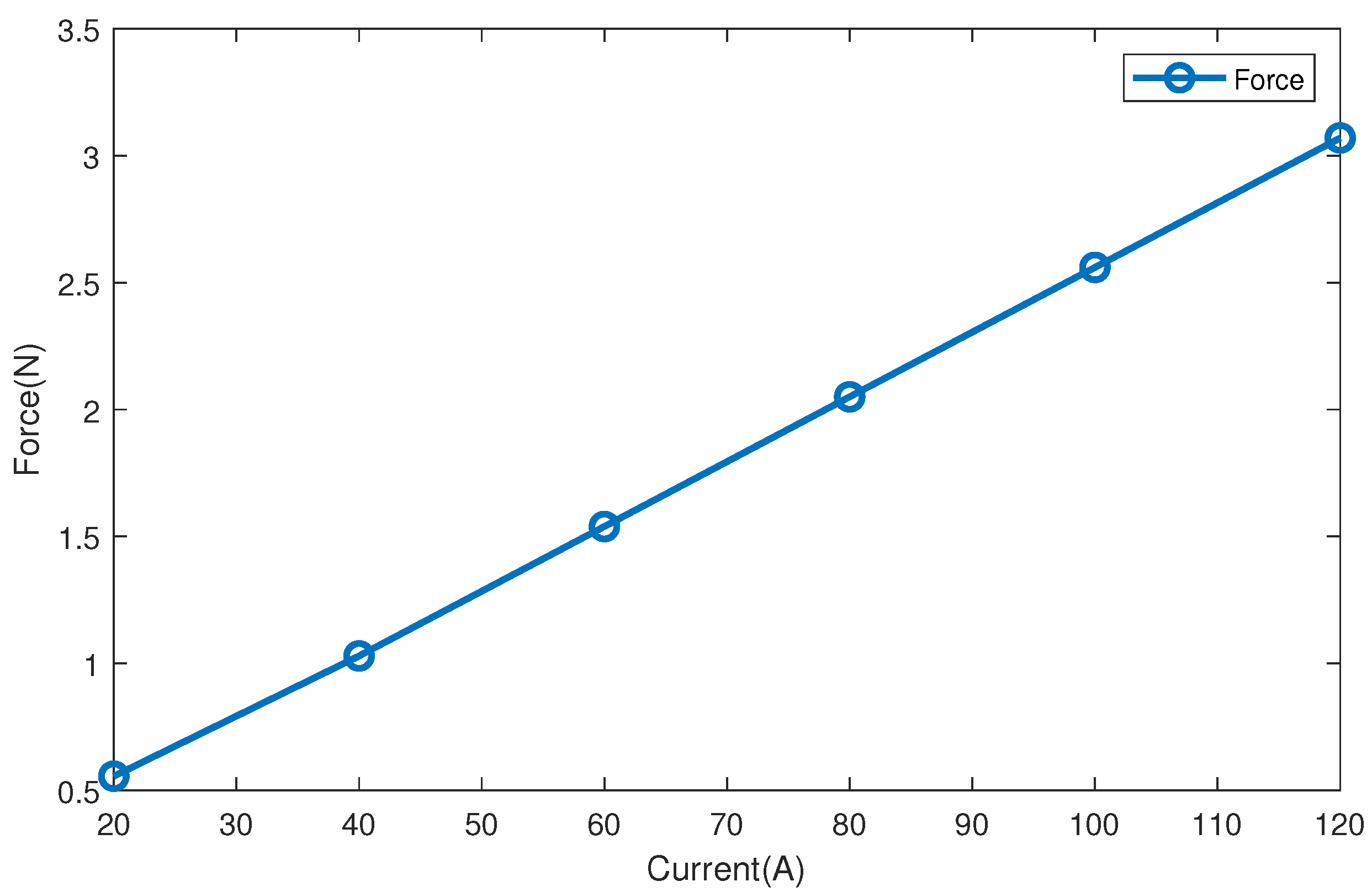
As shown in Figure 10, the relationship between electromagnetic force and current presents a linear trend. When the current increases by 20 A, the electromagnetic force increases by 0.5 N. Because the cross-sectional area of copper wire of electromagnet winding is limited, the maximum current is 120 A and the corresponding axial force is 3.07 N. When the current is 20 A, the corresponding axial force is 0.555 N. Electromagnetic force and the current characteristic table is Table 2.
However, this paper mainly analyzes the axial electromagnetic field of the magnetic suspension balance. The magnetic suspension model is stable in the wind tunnel, and the magnetic force and gravity of other degrees of freedom have been balanced, so the influence on the axial electromagnetic force is very small. For the convenience of analysis and calculation, the influence of electromagnetic coils in other directions is ignored.
In the actual operation, the model is transferred to the center of the experimental section with auxiliary tooling, and then a specific magnetic field is generated by applying current to each electromagnetic coil. A specific magnetic field allows the model to be suspended in the experimental section. When the stable model is suspended, remove the auxiliary tooling, and then pass high-speed airflow in the axial direction. At this time, the model will move backward. At this time, increase the current of the axial coil to make the model return to its original position. It can also adjust the magnetic field distribution to make the model present different attitudes and positions in space.
Some use the calculation formula of the electromagnetic force, ignoring the influence of magnetic flux leakage, some use two-dimensional model calculation, ignoring the nonlinearity of space magnetic field. The three-dimensional model is considered in this paper. The electromagnetic field is a space magnetic field, and the large gap magnetic flux leakage is also considered. The error between each calculation result is less than 4%, but because the experimental device has not been used well, it cannot be compared with the experimental curve for accuracy analysis. This is also a research point in the future.
Due to the principle prototype of magnetic suspension balance in the production process, it is unable to carry out relevant experimental tests. Therefore, it is impossible to compare the simulation results with the experimental results. In the actual system, there may be some factors that are not taken into account. The next step is to build and test the prototype of the magnetic suspension balance.
6. Conclusions
This paper analyzes the electromagnetic field of the axial coil of the magnetic suspension wind tunnel balance, gives the expression of the spatial magnetic field of the magnetic suspension wind tunnel balance, and carries out the digital modeling, design, and analysis of the magnetic field generated by the axial coil of the magnetic suspension wind tunnel balance. The influence of the shape, size and distance of coil, and the segment number and a pitch angle of suspension model on the electromagnetic system is studied. The calculation results show that the axial electromagnetic force can be increased by increasing the diameter of the axial coil and the number of segments of the magnetic rod, reducing the distance between the axial coil and the angle of the suspension model in a certain range. The larger the electromagnetic force is, the higher the bearing capacity of the wind tunnel will be. The conclusion of the whole paper can guide the design and development of the prototype.
Author Contributions
M.Z. is responsible for research ideas and revise of the paper. W.X. is responsible for the calculation and Simulation of electromagnetic field and the writing and communication of the paper. Z.L. and F.D. provide ideas for the platform construction and guidance for the paper. All authors have read and agreed to the published version of the manuscript.
Funding
This work was supported by the National Key R D Program of China under Grant 2016YFB1200600.
Institutional Review Board Statement
The study did not involve humans or animals.
Informed Consent Statement
The study did not involve humans.
Data Availability Statement
The study did not report any data.
Acknowledgments
Thanks to Liming Yin for his special assistance and valuable experience for our research.
Conflicts of Interest
The authors declare no conflict of interest.
References
- Ocokoljić, G.; Damljanović, D.; Rašuo, B.; Isaković, J. Testing of a standard model in the VTI’s large-subsonic wind-tunnel facility to establish users’ confidence. FME Trans. 2014, 42, 212–218. [Google Scholar] [CrossRef]
- Koga, S.; Hidaka, A.; Tagai, R.; Kimura, T.; Yoshinaga, T.; Shinji, N. Dynamic Stability Testing of a Reentry Lifting Capsule in a Transonic Wind Tunnel. In Proceedings of the 52nd Aerospace Sciences Meeting, National Harbor, MD, USA, 13–17 January 2014.
- Sato, T.; Kubota, T.; Fujita, K.; Okada, T. Overview of the “MELOS1” Mars Exploration Mission. In Proceedings of the 57th Space Sciences and Technology Conference, Hai Phong City, Vietnam, 14–19 July 2013. [Google Scholar]
- Iizuka, H.; Morimoto, T. Conformal Contact Between a Rubber Band and Rigid Cylinders. ASME J. Appl. Mech. 2012, 79, 1–4. [Google Scholar]
- Buehrle, R.D.; Young, C.P., Jr.; Balakrishna, S.; Kilgore, W. Experimental study of dynamic interaction between model support structure and a high speed research model in the national transonic facility. In Proceedings of the 35th Structures, Structural Dynamics, and Materials Conference, Hilton Head, SC, USA, 18–20 April 1994; pp. 2428–2437. [Google Scholar] [CrossRef]
- Fan, Z. Measurement of Aerodynamic Forces and Moments in Wind Tunnels. Encycl. Aerosp. Eng. 2010. [Google Scholar] [CrossRef]
- Rhew, R.D. NASA LaRC Strain Gauge Balance Design Concepts. In First International Symposium on Strain Gauge Balances; NASA/CP-1999-209101/PT2; NASA Langley Research Cente: Hampton, VA, USA, March 1999; Volume 2, pp. 525–541. [Google Scholar]
- Morgenstern, J.M. How to Accurately Measure Low Sonic Boom or Model Surface Pressure in Supersonic Wind Tunnels. In Proceedings of the 30th AIAA Applied Aerodynamics Conference, New Orleans, LA, USA, 25–28 June 2012. [Google Scholar] [CrossRef]
- Hefer, G. Wind Tunnel Model Support with Vibration Detection Balance and Counter Vibration Means. U.S. Patent 5,644,075, 1 July 1997. [Google Scholar]
- Uselton, B.L.; Haberman, D.R. Summary of Sting Interference Effects for Cone, Missile, and Aircraft Configurations as Determined by Dynamic and Static Measurements. In Proceedings of the 9th Atmospheric Flight Mechanics Conference, San Diego, CA, USA, 9–11 August 1982. [Google Scholar] [CrossRef]
- Ericsson, L.E.; Reding, J.P. Transonic Sting Interference. J. Spacecr. Rocket. 1980, 17, 140–144. [Google Scholar] [CrossRef]
- Kai, D.; Sugiura, H.; Tezuka, A. Development of Magnetic Suspension and Balance System for High-Subsonic Wind Tunnel. In Proceedings of the 2018 AIAA Aerospace Sciences Meeting, Kissimmee, FL, USA, 8–12 January 2018. [Google Scholar]
- Jenkins, T.P.; Plemmons, D.H. Improving measurement with spinning mirrors, schlieren images and magnetic suspension. Aerosp. Am. 2017, 55, 17. [Google Scholar]
- Zhai, M.; Long, Z.; Li, X. A New Strategy for Improving the Tracking Performance of Magnetic Levitation System in Maglev Train. Symmetry 2019, 11, 1053. [Google Scholar] [CrossRef] [Green Version]
- Kai, D.; Sugiura, H.; Tezuka, A. Magnetic Suspension and Balance System for High-Subsonic Wind Tunnel. AIAA J. 2019, 57, 2489–2495. [Google Scholar] [CrossRef]
- Di Tullio, V.; Proietti, N. New Insights to Characterize Paint Varnishes and to Study Water in Paintings by Nuclear Magnetic Resonance Spectroscopy (NMR). Magnetochemistry 2020, 6, 21. [Google Scholar] [CrossRef] [Green Version]
- Zhai, M.; Long, Z.; Li, X. Calculation and evaluation of load performance of magnetic levitation system in medium-low speed maglev train. Int. J. Appl. Electromagn. Mech. 2019, 61, 519–536. [Google Scholar] [CrossRef] [Green Version]
- Ahmadivand, A.; Gerislioglu, B. Directional Toroidal Dipoles Driven by Oblique Poloidal and Loop Current Flows in Plasmonic Meta-Atoms. J. Phys. Chem. C 2018, 122, 24304–24308. [Google Scholar] [CrossRef]
- Gerislioglu, B.; Ahmadivand, A. The Observation of High-Order Charge–Current Configurations in Plasmonic Meta-Atoms: A Numerical Approach. Photonics 2019, 6, 43. [Google Scholar] [CrossRef] [Green Version]
- Zhang, J.; Wang, C. Numerical Study of Lateral Migration of Elliptical Magnetic Microparticles in Microchannels in Uniform Magnetic Fields. Magnetochemistry 2018, 4, 16. [Google Scholar] [CrossRef] [Green Version]
Figure 1.
Structure diagram of magnetic suspension wind tunnel system.

Figure 2.
Structure diagram of magnetic suspension balance body.

Figure 3.
Simplified diagram of axial coil position relationship.

Figure 4.
Finite element analysis of magnetic suspension wind tunnel balance (MSBS).

Figure 5.
(a) Magnetic field intensity vector diagram. (b) Magnetic induction intensity.

Figure 6.
(a) The influence of coil shape on the relation curve between current and electromagnetic force. (b) The influence of coil shape on the relation curve between current and magnetic induction intensity.
Figure 6.
(a) The influence of coil shape on the relation curve between current and electromagnetic force. (b) The influence of coil shape on the relation curve between current and magnetic induction intensity.

Figure 7.
(a) The influence of coil distance on the relation curve between current and electromagnetic force. (b) The influence of coil distance on the relation curve between current and magnetic induction intensity.
Figure 7.
(a) The influence of coil distance on the relation curve between current and electromagnetic force. (b) The influence of coil distance on the relation curve between current and magnetic induction intensity.

Figure 8.
(a) Influence of magnetic rod in suspension model on relation curve of current and electromagnetic force. (b) The influence of magnetic rod on the relation curve between distance and magnetic induction intensity. The distance refers to the distance from the point to the end of the magnetic rod, and the point is on the axial line of the magnetic rod.

Figure 9.
Influence of pitch angle of suspension model on relation curve of current and electromagnetic force.
Figure 9.
Influence of pitch angle of suspension model on relation curve of current and electromagnetic force.

Figure 10.
Relation curve of electromagnetic force and current.axial coil distance 264 mm.


Table 1.
The parameters of axial coil.
| Inductance | Resistance Value | Intimate Size | Coil Size | Section Size | Total Turns |
|---|---|---|---|---|---|
| 5.52 (mH) | 0.5 (Ohm) | none | 120 × 220 (mm) | 2 × 8 (mm) | 125 |
Table 2.
Electromagnetic force and current characteristic table.
| Current (A) | 20 | 40 | 60 | 80 | 100 | 120 |
|---|---|---|---|---|---|---|
| Ampere turns | 2500 | 5000 | 7500 | 10,000 | 12,500 | 15,000 |
| axial force (N) | 0.555 | 1.029 | 1.539 | 2.050 | 2.560 | 3.070 |
Publisher’s Note: MDPI stays neutral with regard to jurisdictional claims in published maps and institutional affiliations. |
© 2021 by the authors. Licensee MDPI, Basel, Switzerland. This article is an open access article distributed under the terms and conditions of the Creative Commons Attribution (CC BY) license (http://creativecommons.org/licenses/by/4.0/).
Share and Cite
MDPI and ACS Style
Zhai, M.; Xia, W.; Long, Z.; Dou, F. Numerical Computation and Analysis of Electromagnetic Field in Magnetic Suspension and Balance System. Magnetochemistry 2021, 7, 33. https://0-doi-org.brum.beds.ac.uk/10.3390/magnetochemistry7030033
AMA Style
Zhai M, Xia W, Long Z, Dou F. Numerical Computation and Analysis of Electromagnetic Field in Magnetic Suspension and Balance System. Magnetochemistry. 2021; 7(3):33. https://0-doi-org.brum.beds.ac.uk/10.3390/magnetochemistry7030033
Chicago/Turabian StyleZhai, Mingda, Wentao Xia, Zhiqiang Long, and Fengshan Dou. 2021. "Numerical Computation and Analysis of Electromagnetic Field in Magnetic Suspension and Balance System" Magnetochemistry 7, no. 3: 33. https://0-doi-org.brum.beds.ac.uk/10.3390/magnetochemistry7030033
Note that from the first issue of 2016, this journal uses article numbers instead of page numbers. See further details here.