Article

A Decision-Making Methodology Based on Expert Systems Applied to Machining Tools Condition Monitoring

by
Manuel Casal-Guisande
*,
Alberto Comesaña-Campos
*,
Alejandro Pereira
,
José-Benito Bouza-Rodríguez
and
Jorge Cerqueiro-Pequeño
Department of Design in Engineering, University of Vigo, 36208 Vigo, Spain
*
Authors to whom correspondence should be addressed.
Mathematics 2022, 10(3), 520; https://doi.org/10.3390/math10030520
Submission received: 29 December 2021 / Revised: 25 January 2022 / Accepted: 4 February 2022 / Published: 6 February 2022
(This article belongs to the Special Issue Fuzzy Applications in Industrial Engineering)

Abstract

:
The workers operating and supervising machining tools are often in charge of monitoring a high number of parameters of the machining process, and they usually make use of, among others, cutting sound signals, for following-up and assessing that process. The interpretation of those signals is closely related to the operational conditions of the machine and to the work environment itself, because such signals are sensitive to changes in the process’ input parameters. Additionally, they could be considered as a valid indicator for detecting working conditions that either negatively affect the tools’ lifespan, or might even put the machine operators themselves at risk. In light of those circumstances, this work deals with the proposal and conceptual development of a new methodology for monitoring the work conditions of machining tools, based on expert systems that incorporate a reinforcement strategy into their knowledge base. By means of the combination of sound-processing techniques, together with the use of fuzzy-logic inference engines and hierarchization methods based on vague fuzzy numbers, it will be possible to determine existing undesirable behaviors in the machining tools, thus reducing errors, accidents and harmful failures, with consequent savings in time and costs. Aiming to show the potential for the use of this methodology, a concept test has been developed, implemented in the form of a short case study. The results obtained, even if they require more extensive validation, suggest that the methodology would allow for improving the performance and operation of machining tools, as well as the ergonomic conditions of the workplace.

1. Introduction

Machining processes are pervasive in many different environments, such as, for example, the biomedical [1], aerospace and automotive industries [2,3], among many others.
Generally speaking, the last few decades have seen an increasing trend toward the reduction in the costs associated with the manufacturing process, while at the same time aiming as much as possible to increase product quality and to reduce process times [4,5]. Said costs are not only related to the process itself, nor to its quality control operations, but also to the machine’s own infrastructure, and to the workers’ training. Additionally, several other potential factors must be considered that could result—either directly or indirectly—in additional process-related costs.
In order to achieve those goals, it is fundamental to keep the process under tight control, it being common that companies put human operators in charge of monitoring computer numerical control (CNC) machine tools and making decisions about when to replace the cutting tool [6]. It is frequent in those cases to find operators that barely show the expertise and skills that are required to properly assess the wear degree of the tool [7]. Delaying tool replacement might lead to unpredictable process failures, to excessive energy demanded by the machine, or to the emerging of surface defects on parts, among other potential undesirable consequences for the machine and for the product itself [6,7,8,9,10,11,12].
Under these circumstances, tool condition monitoring might be of help to determine its wear level. Several methodologies exist helping in such monitoring, either partially or completely, which in a general way might be classified into two categories [7,8,11,12,13,14,15,16]: direct and indirect methods. Direct methods are those that extract characteristics directly from the tool itself [7,8,11,12,13,14,15,16]. Despite their immediacy in geometry measurement, the fact that the tool is most of the time in contact with the machined part, and the potential presence of other elements also in contact with it, such as chips or the cutting fluid itself, makes it difficult to use these methods in industrial environments, leaving them mainly for laboratory use [13,15]. On the other hand, indirect methods rely on capturing data derived from the process that might be related to the wear of the tool itself [7,8,11,12,13,14,15,16]. Indirect methods are less accurate than direct ones, but they are more appropriate for applications in industrial environments [15]. Among the indirect approaches, the analysis of the cutting sound emissions derived from the machining process, which can be easily captured, stands out, thus establishing itself as one of the less costly process condition monitoring methods [17].
In this paper, a new methodology is proposed and developed at a conceptual level, based on expert systems that incorporate a reinforcement strategy into their knowledge base, oriented towards the monitoring of the machining tool condition. Our goal is to extend the operator’s capabilities, making it a complementary element in the decision related to the interpretation of the quality of the machining operations in real time. Starting with the information coming from several sources, both qualitative and quantitative (for example, the cutting sounds), the methodology allows for identifying those process input variables with a major influence on tool wear, decreasing its lifespan, and that therefore must be reviewed. To do so, a system is proposed in which audio processing algorithms are combined with a decision manager grounded in the use of fuzzy inference engines and the application of hierarchization techniques based on vague fuzzy numbers.
This work is organized as follows. In the rest of this section, an explanation about expert systems and its applications in the machining sector is given. Furthermore, a description of hierarchization systems is developed. After that, in the “Materials and Methods”, in Section 2.1, a general schematic of the methodology is presented and described. After that, in Section 2.2, a detailed implementation of the methodology is proposed. Thereafter, in Section 3, a brief demonstration of the methodology is developed to verify it. Finally, in Section 4, a comparative analysis is made, while Section 5 summarizes the conclusions and future works.

1.1. Expert Systems as Complementary Elements in Decision-Support Systems

Decision-support systems, included amongst the information systems, have established themselves as their own discipline because of their versatility and adaptability [18,19,20,21]. They are multi-disciplinary grade systems that allow the integration of different techniques and methods of information management. Such systems have been used in the field of artificial intelligence (AI), and have been used as parts of AI components, which become complementary elements in the decision-making process. In this line, the use of expert systems as decision-support complementary elements has been a regular practice since the last years of the 20th Century. Expert systems, whose development started in the 1960s [22,23,24], possess the ability to solve problems by simultaneously combining the knowledge of many experts that complement and optimize the decision-making process, supported by decision-support systems [25]. Generally speaking, for the definition of an expert system, it is necessary to have a knowledge base, a human–machine interface, an inference engine, and a defined process for collecting and processing the data from the problem [22,23,26,27,28,29,30]. After being designed, these systems can be supported by the use of different techniques and approaches that allow the representation of the previously mentioned components [31,32], with the objective of transforming the input information until an appropriate result is obtained. In this sense, and because of their relevance in the field of study, rule-based systems [33], neural networks [34] and fuzzy logic-based inference systems [35,36], among others, deserve to be highlighted.
From all that has been explained above, and taking into account the fundamentals of design science research established by Hevner et al. [21,37], it is possible to work on the development of software-supported artifacts that allow us to solve human problems by using expert systems, and which could in turn be integrated into true decision-support methodologies. This is basically what is achieved in this paper: the design of a methodology that allows us to manage decisions related to the lifespans of machining tools.

1.2. Expert Systems in Machining Applications

There are many applications related to the monitoring of cutting tools’ conditions, some of them applying expert systems and differing in the inference engine used. In relation to this, the work by Elangovan et al. from 2010 [38] proposed to discover hidden relationships within vibration signals by applying data mining techniques. The authors of that article collected vibration signals from a lathe tool under different wear conditions. Next, a series of statistical and histogram-related parameters were determined. Because of the amount of parameters available, the authors applied feature selection techniques to reduce dimensionality and thus facilitate the calculations. With the resulting characteristics, the authors trained two different architectures: (1) Bayes Net and (2) Naïve Bayes. Better performance was observed in the statistical features case, with a slightly higher accuracy over the test set: the Bayes Net case achieved 86.34%, compared to the 85.28% of Naïve Bayes. In an article from 2011 that presents a work methodology similar to that from their 2010 work, Elangovan et al. [39] propose the use of a decision tree, the algorithm C4.5, for dimensionality reduction and failure condition detection applied to the characteristics extracted from tool vibration signals in CNC turning operations. In their best configuration, the authors observed an accuracy in the classification of the tool condition of 77.22% with respect to the test set. The authors indicate the simplicity and power of the proposed system, even if they also point out that their results cannot be applied indiscriminately to other operations. Mesina et al. [40] propose a neuro-fuzzy system aimed towards the prediction of tool conditions in milling processes. The information input into the system comes from the cutting forces, the acoustic emissions, the spindle current, the cutting parameter index, and the condition of the tool. First, the authors trained a multilayered neural network oriented towards the determination of the tool’s wear. After that, taking the previously determined architecture as a reference, a fuzzy logic-based algorithm was built and adapted, aiming to emulate the behavior of the previously defined neural network, which allows one to estimate the tool condition. Broadly speaking, the authors claim the benefits associated with the use of a neuro-fuzzy system for the detection of tool wear, which allows one to determine a linguistic model from the knowledge that is embedded into a neural network. In the same line, Saglam and Unuvar [41] propose a monitoring system, applied to face milling processes, based on the study of the cutting forces and general process parameters (cutting speed, cutting, feed rate, and axial cutting depth) using a multi-layer neural network, oriented towards the prediction of tool wear and surface finish. The authors mention that the proposed architecture is capable of determining flank wear with a 23% (30 to 40 µm) mean error value, and surface roughness with a 20% (5 to 30 µm) mean error value, thus providing an alternative means of assessing tool condition, free from the subjectivity associated with human operators. The work by Li and Elbestawi [42] proposes a Multiple Principal Component Fuzzy Neural Network for the classification of patterns in the monitoring of machining conditions, taking into account multiple information sources (such as forces, vibrations, and power used by the driving shaft). The authors indicate that their architecture achieved accuracy levels of 84% in tests carried out using new data in similar working conditions, while these values dropped to 80% when the working conditions were different from those in the model’s definition. In the work by Patange et al. [43], a Machine Learning approach is proposed aimed at the condition monitoring of a milling cutter in a vertical machining center. By acquiring the signals associated with the vibration of four milling cutter inserts, and applying statistical-based approaches to extract features together with decision trees and random forest, the authors were able to determine the most relevant characteristics influencing the tool wear. The authors tested different algorithms, such as J84, random forest and logistic model tree classifier, obtaining accuracy levels of 85.5%, 88.16% and 88.33%, respectively. Even though the logistic model tree classifier showed a higher accuracy, the authors point out that the best architecture was random forest, because of its lower time needed to train the architecture. In the work by Zaloha et al. [44], an expert system is designed for the condition monitoring of a machining tool that uses an adaptive neuro-fuzzy inference system (ANFIS) as its engine, aiming to describe the relationship between the cutting tool’s flank wear and the power of the vibration signal. The authors implemented the system into MATLAB®, and they indicate that the best results were obtained using triangular membership functions for the input variables, and constant ones for the output variables. They point out that the mean error in tool wear determination was 2.03%. The work by Silva et al. [45] proposes the combination of two neural networks and an expert system that uses Taylor’s equation for the calculation of the tool’s lifespan, operating on the features extracted from a collection of sensors (vertical vibration, sound emission, forces and spindle current), aiming to classify the tool wear condition. The authors used two network architectures: self-organizing map and adaptive resonance theory, with the former showing a higher accuracy level. They also mention that the use of a Taylor model focused on the identification and removal of outliers, together with the neural network, helps to improve its performance. In the work by Aralikatti et al. [46], starting with the cutting force and the vibration signals and extracting from them a series of features by applying wavelet transformations, a dataset was built from which the most representative characteristics can be derived by using the J48 algorithm, which, in turn, are used to train the Naïve Bayes classification algorithm. The authors indicate that the Naïve Bayes algorithm showed accuracy levels of 96.667% when using the information coming from the cutting forces, and 70% when the information coming from the vibrations was used, hence their conclusion that the cutting forces signals are better data for diagnosing tool failure than the vibrations signals. In the work by Zuperl et al. [47], starting from the cutting force signals, the use of ANFIS-based approaches and a neural network for the monitoring of tool conditions in end-milling processes is proposed. ANFIS is used to determine the flank wear derived from the cutting forces, showing an accuracy level of 95.3% with varying work conditions. After that, a neural network is used to determine the tool condition (normal or broken/worn). In the work by Lin et al. [48], an intelligent system is presented, oriented towards machine tool condition monitoring in milling processes. Spindle electrical current data are compiled, and the relevant features are extracted by means of the wavelet transform, all of which is used for training a least squares support vector machine (LS-SVM) classification algorithm. The authors indicate that the developed classifier showed an AUC level of 0.974, very close to one, with high capabilities to determine the milling tool condition. Additionally, they also indicate that a motor current sensor is inexpensive, and because of that, it is a cheaper option than other alternatives for monitoring tool condition.
Generally speaking, it can be observed that most of the analyzed articles either choose cutting forces or vibrations as input data signals. Additionally, it is common to use approaches related with statistical artificial intelligence models that need to be trained, i.e., they need a prior dataset to exist in order to train a learning algorithm, which will later be in charge of the prediction. The use of these approaches implies the identification of results from data that might not be evident or easily deduced, which involves assuming a lack of explicit knowledge on the machining process to be studied. The use of hybrid approaches incorporating neural networks and fuzzy logic within ANFIS systems partially improves this interpretation and understanding of results. Because of all this, proposing symbolic intelligence models does not only optimize knowledge representation, but it also diversifies its interpretation, and formalizes its transmission among experts.

1.3. Hierarchization Processes

The use of expert systems within a decision methodology framework may require other complementary perspectives to enrich the initial data dumped into these systems. In the case of complex decisions, such as the one presented in this paper, data must be processed within the scope of multi-criteria problems, which may require a hierarchy of values from a certain number of valuation criteria. Two different approaches might result [49]: (1) multi-objective problems, in which the search for an optimized value is performed according to the established criteria, and (2) multi-attribute problems, in which it is necessary to determine which one of the values best satisfies the initial criteria from a certain number of values. In this work, multi-attribute hierarchization techniques are used because both the values and the criteria are delimited and defined. These kinds of approaches, however, among which the scoring and the pair-comparison methods are the most representative, must always consider the efficient reduction or concision of the number of values and criteria to be considered. In this sense, Miller [50] established that human abilities of consideration are limited to seven simultaneous facts.
Different methods exist that we could consider as “classic”, and these allow us to make a choice from a triad of values and to establish a classification. We might highlight Pugh’s Decision Matrix [51,52], the Hierarchical–Analytical Method [53,54], distance-based methods such as TOPSIS [49,55] or VIKOR [56], outranking methods such as PROMETHEE [57,58], and the methods based on the “utility” concept, such as MAUT [59], among others.
In the last decade, and as a consequence of the development of inference systems, hierarchization methods have been developed, aiming to reduce the inconsistency, uncertainty and inaccuracy issues commonly associated with the methods considered “classic”. The use of fuzzy algebra [60,61] has involved the incorporation of an efficient uncertainty control into hierarchization processes. In this sense, the algebra of vague sets is of special interest [62], which might be interpreted as intuitionistic fuzzy sets [63]. This is an approach that arises from the re-interpretation of the classical fuzzy set, extending the use of the membership function concept, and which is being used for multi-attribute problems with multiple decision-makers [64]. In essence, a vague fuzzy set [62] determines the interval within which the degree of membership of a value to a given fuzzy set lies, defining the limits of the membership and non-membership levels to that fuzzy set. Vague numbers were developed later than intuitionistic numbers, although they are in essence the same, using a similar reasoning and interpretation [65,66]. Both in the classic fuzzy sets and in the generalization that the fuzzy vague sets represent, the “membership” concept is associated with a degree of membership, in which a specific value complies with—or affirms—a certain premise when evaluated within a closed interval [0, 1], with 0 being the null degree and 1 the maximum degree of membership, respectively. Based on that definition, intuitionistic numbers—being vague numbers for all intents and purposes [63]—introduce the “non-membership” function concept, similar to the abovementioned classic fuzzy set, that is, a measurement of the degree, between 0 and 1, to which a specific value does not meet, or negates, a given premise. This conceptualization was adopted by Gau and Buehrer [62] in their vague numbers definition, establishing similar “truth-membership” and “false-membership” functions.
Based on this definition, which extends the concept of “membership” associated to the fuzzy set by establishing evidence of membership and non-membership to the set, different hierarchization methods have been developed. Combining the algebra of vague numbers with aggregation operators such as the Weighted Geometric (WG) and the Ordered Weighted Geometric (OWG) [67,68], Xu and Yager [67] proposed in 2006 a set of hierarchization operators derived from those already mentioned for this type of number: the Intuitionistic Fuzzy Weighted Geometric (IFWG) operator, the Intuitionistic Fuzzy Ordered Weighted Geometric (IFOWG) operator, and the Intuitionistic Fuzzy Hybrid Geometric (IFHG) operator [64,67]. These operators allow us to improve the multi-attribute hierarchization process, starting from the expression of value comparison with respect to criteria such as the vague fuzzy numbers. In this sense, these methods are able to improve the accuracy and control the uncertainty of the hierarchization process [67].

2. Materials and Methods

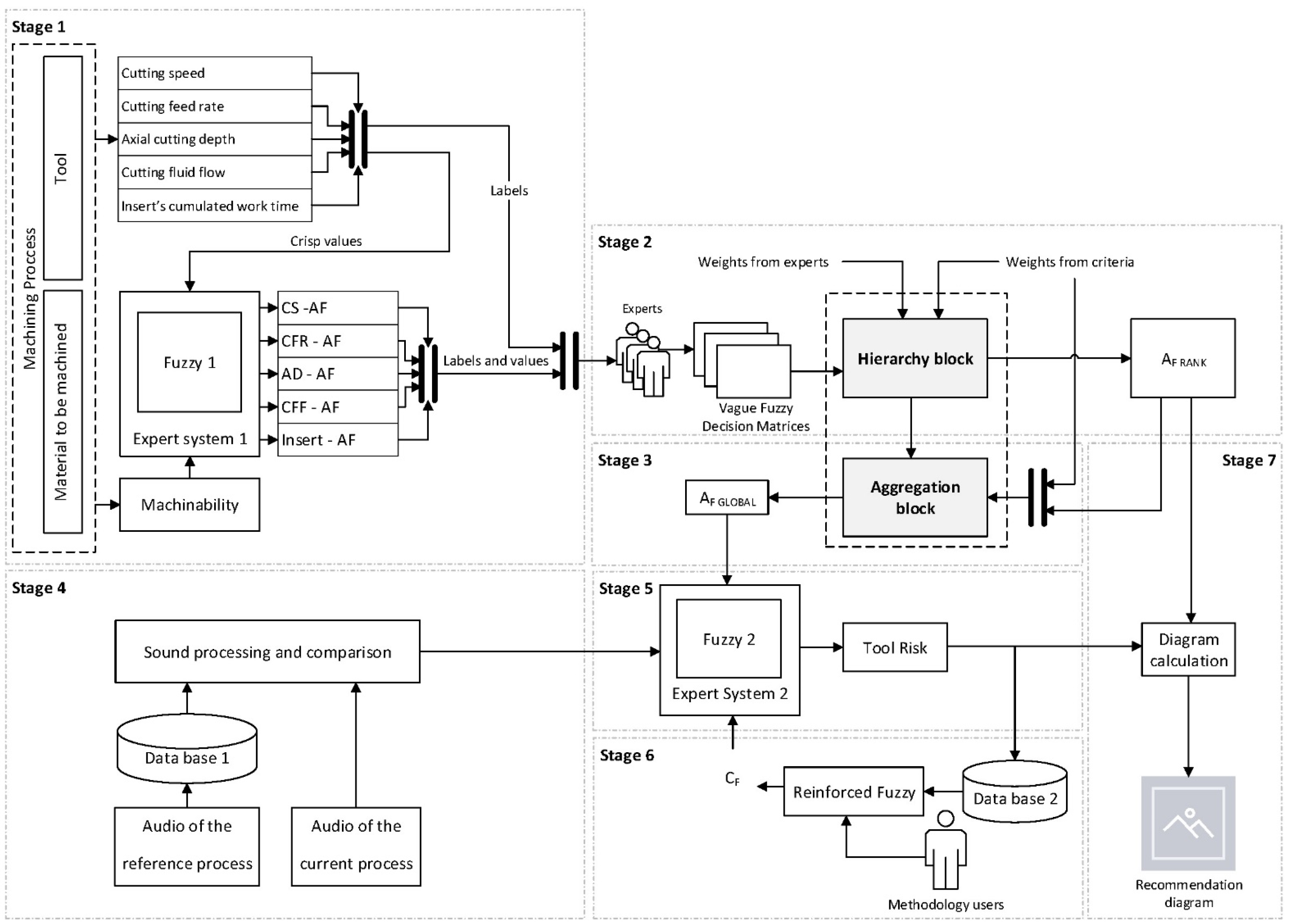
2.1. Definition of the Methodology

As already mentioned, the objective of this paper is to propose and develop a new methodology, based on expert systems with reinforced fuzzy, aimed at the monitoring of machining tools’ condition.
As explained in Section 1, the use of expert systems is common in decision-making processes involving a large amount of heterogeneous data, both from quantitative and qualitative sources. Any industrial process is affected by the decisions that determine all the phases of its correct operation. In the case of the condition monitoring of machining tools, the decisions related to their operation are conditioned by a series of well-known and studied parameters, whose influence on the manufacturing process is derived from both individual parameters and collective behaviors. Even if the isolated influence can be estimated by means of quantitative statistical methods, the multi-criteria assessment—i.e., the conjoint influence of all the parameters—responds to heuristic knowledge models. The experts that manage the process and the machines are the ones who know their behavior when different values of the machining parameters are obtained. Collecting and representing the knowledge and expertise of those experts, not only assessing the quantitative data but also considering the qualitative influence derived from the heuristic interpretation, is the main potential value of expert systems. By creating that knowledge base, and defining a suitable inference mechanism, the expert system has the potential to replicate human reasoning, and to produce enough information to complement the decision process. The proposed methodology, therefore, will provide support to the decision-making process related to the lifespan of the machining tools, by integrating its behavior detection and inferring a risk value that is associated with its usage. After that, the methodology will produce a sector diagram with recommendations to be followed to help preserve the machining tool and avoid mistakes.
Figure 1 shows a schematic of the proposed methodology, which considers a series of stages/blocks that are elementary constituents of the expert systems that will be developed in more detail in Section 2.2., “Implementation of the Methodology”.
Generally speaking, the methodology consists of 7 differentiated stages that can be seen in Figure 1. First, Stage 1, Expert System 1, which uses a Mamdani-type fuzzy inference engine, is in charge of processing the general parameters (cutting speed, cutting feed rate, axial cutting depth, use of coolant, and cumulated use hours of the tool), determining as its output a series of factors associated to each one of the process parameters, named as “aggressiveness factors”: CS-AF (cutting speed aggressiveness factor), CFR-AF (cutting feed rate aggressiveness factor), AD-AF (axial depth aggressiveness factor), CFF-AF (cutting fluid flow aggressiveness factor) and Insert-AF (insert aggressiveness factor), which aim to determine how damaging each one of those process parameters is to the tool’s lifespan. After that, in Stage 2, by contemplating a series of experts and criteria, the hierarchization of those aggressiveness factors is carried out using vague fuzzy numbers, determining a ranking of said factors, and in Stage 3, the Global Aggressiveness Factor of the tool derived from the aggregation process is calculated. In parallel, in Stage 4, the machining process audio data are captured and processed, determining a series of characteristic metrics that, together with the tool’s Global Aggressiveness Factor, are fed into Expert System 2. In Stage 5, Expert System 2, which also uses a Mamdani-type fuzzy inference system, produces the Tool Risk level as its output. It is relevant to highlight a distinctive feature of this second expert system: it incorporates a reinforcement block, implemented in Stage 6 and named “Reinforcement Fuzzy”, which represents a reinforcement strategy based on Expert System 2′s knowledge base. This block will determine a correction factor that will allow for correcting potential undesired operations in the system by adjusting the logical structure and the importance of the production rules of Expert System 2. Finally, in the 7th and last stage, by contemplating the tool risk level and the different aggressiveness factors, it will be possible to construct a sector diagram that will be used to graphically visualize the factors’ values (sector areas) and the tool risk level (thickness).

2.2. Implementation of the Methodology

The methodology under development is based on the definition of two sequential expert systems whose main flowchart is shown in Figure 1, which includes the stages that will be described next. Table 1 shows the general parameters to be defined before using the methodology, which will be specified in Table 5 for the case study.

2.2.1. First Expert System

The first expert system that the methodology integrates aims to solve the problem that the modeling of the factors potentially affecting the machining process involves. Its goal is to provide support to the multi-criteria decision problem by establishing the knowledge base, the application interface and the inference engine.
The input and output variables are not represented as directly measurable variables, but as parameters influencing the operation of the machining tool used. With this, the knowledge base for the first expert system is created, based on the use of a deductive approach that starts from the input variables, so that by means of symbolic reasoning it succeeds in establishing a value for the output variables. First-order logic based on “IF-THEN”-type declarative rules is used for said reasoning. For example: IF (Cutting_speed is Low) AND (Machinability is Low) THEN (Cutting_speed_aggressiveness_factor is Medium); IF (Cutting_speed is Low) AND (Machinability is Medium) THEN (Cutting_speed_aggressiveness_factor is Low); IF (Insert_working_hours is High) AND (Machinability is Low) THEN (Insert_working_hours_agressiveness_factor is High).
The set of declarative rules makes up the knowledge base for the first expert system, and were created based on the input of a collection of machining experts who, by means of these rules, are able to represent their specific expertise and knowledge. This abstract knowledge can be connected to specific evidence, defining in this way the set of inference rules. Therefore, the knowledge base will be composed of all those syllogisms that relate the input variables with the output variables, and that reflect the specific expert knowledge, considering the correct operation of the machine as a basic premise to be observed. In this case, the inference engine is a fuzzy inference system, indicated as the “Fuzzy 1” block in Figure 1. It is in charge of processing the general variables in the machining process—in this instance those shown in Table 1 in the “General Variables of the Machining Process” cell: cutting speed and tool feed rate, axial cutting depth, cooling fluid flow, cumulated work time (expressed in minutes) of the current tool, and material type of the part to be machined, among other possible ones.
The output of that system produces a factor linked to each of the input variables, by means of the inference obtained after the qualitative valuation derived from their fuzzyfication, named the “aggressiveness factor” of the variable considered. This is a new term that aims to group together the effects of other well-known factors, as well as other machining process descriptors. Clearly, it is not a term that groups together the statistical influence of other elements derived from specific studies, but it does represent their experimental or observed influence. The inference system will be of a Mamdani type [69,70,71,72]. The Mamdani system is a deductive inference method based in the use of declarative rules expressed in a common language and combined by means of fuzzy sets. The main characteristics of this inference system are determined by the nature of its variables. In this case, both the input variables—or antecedents—and the output variables—or consequents—are represented by means of trapezoidal membership functions, and they are linked using rules articulated with AND-type [72] operators. The Mamdani system implication method entails that the consequent is expressed as a fuzzy set, and the antecedents are combined by means of implication functions, such as the minimum and maximum [72]. The fact that the membership functions are mostly trapezoidal addresses the limitation of not being able to guarantee full membership before the specific qualification of each of the input and output variables.
On the other hand, “AND”-type antecedent implications are used, which use the minimum function for the combination of the input variables, ensuring that the creation of the rules implies the combination of several input variables to achieve a single consequent. Alternatively, if single antecedents or maximum implications with “OR”-type conjunctions are used, then the knowledge would be represented in a very biased way, as only one variable would be considered in each rule. When using “AND”-type implications, the participation of several rules in the evaluation of the consequent is necessary, which thus demands a more complex and deeper knowledge that has a clearer multi-criteria consideration. The output variables are aggregated using a disjunctive approach that determines the defuzzified set by means of the centroid method [72]. There is an exception related to the type of material to be machined, which will be used as a general consideration variable, and which will not determine any specific aggressiveness factor. In this way, for the characterization of the material, a choice was made for a technical parameter associated with that material type’s machinability, obtained in this case from the CES Edupack 2019 software [73]. Said parameter might be interpreted as the relative easiness for a material type to be machined. Thus, a material type would have good machinability if the tool wear and the cutting forces were low, while at the same time the cutting speed could be high for an acceptable surface finish.
Other parameters associated with the processability of the material also exist, such as its conformability or its weldability, which might be integrated into the methodology. Nevertheless, in the current scheme, only the machinability is used, because, besides characterizing the material for machining processes by grouping different mechanical properties, it also expresses relationships with other already-defined general process parameters, such as the cutting speed. Therefore, the different aggressiveness factors aim to express the impacts on the tool’s lifespan, related to each of the general variables corresponding to the process. For example, the factor linked to the cutting speed is the Cutting Speed Aggressiveness Factor (CS-AF).
Despite the fact that Mamdani inference systems [69,70,71,72] are well known, it is required to point out that the inference system that they use is not related to their implication, but to the tautology used to combine and to simulate the knowledge derived from the set of declarative rules representing the knowledge base. Generally speaking, a tautology based in the modus ponens deduction is used, in which the consequent of a premise to be evaluated is a function of the degree of certainty of the antecedent of the rule representing the knowledge used to evaluate such premise. Therefore, in this first expert system, the inference mechanism tautology is related to the different common-language qualifiers used to analyze each one of the input variables, and to relate them to the output variable. Thus, for example, if the variable associated to the cutting speed belongs to a “high” qualification and the material machinability is “low”, then the knowledge is modeled according to the experts’ expertise, resulting in the production of an aggressiveness factor associated to a “high” cutting speed. This implies that, when a premise related to the speed and the machinability is introduced, from this premise a conclusion must be derived. If the premise presents the same membership degree as the one represented in the declarative rule, then its consequent will be the same as the one represented in said rule, using modus ponens reasoning.
Table 2 defines the initial configuration of the inference system for the first expert system, which is used for the calculation of the particular aggressiveness factors related to the different input variables, as has been already mentioned.

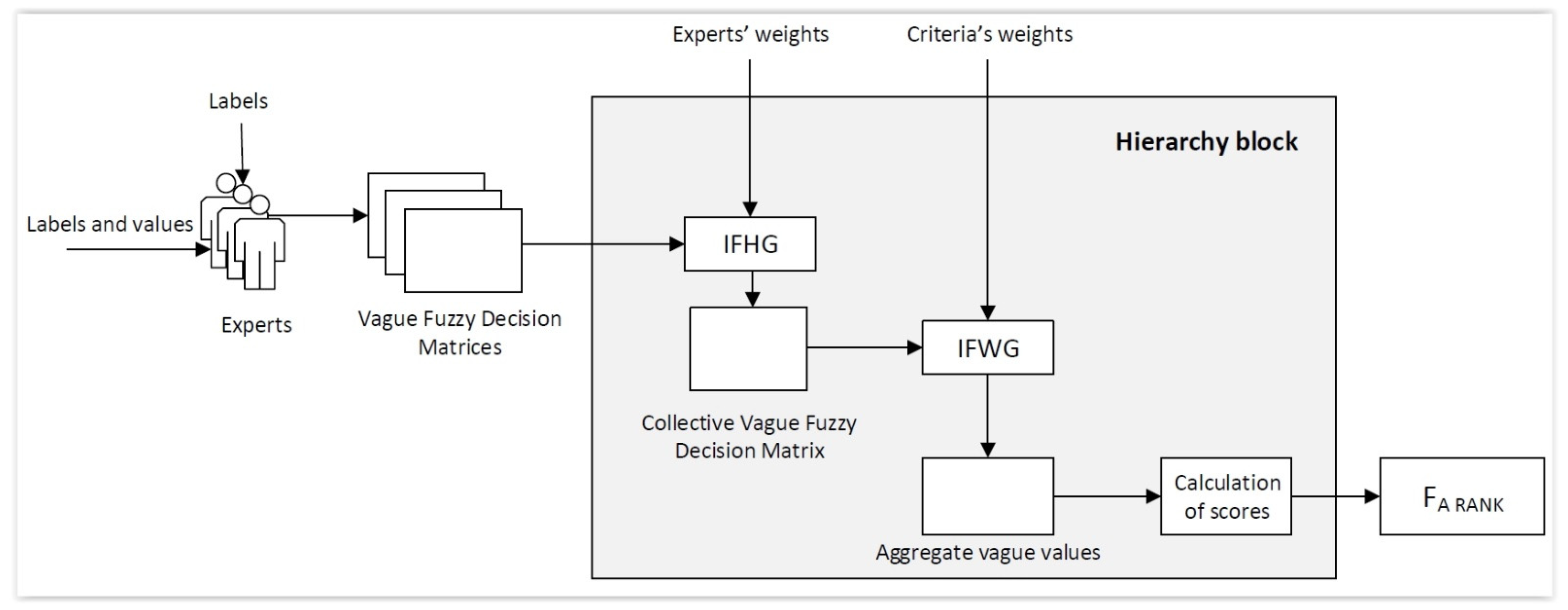
2.2.2. Hierarchization of the Aggressiveness Factors

The hierarchization block in Figure 1 is shown in more detail in Figure 2. This block is in charge of performing the hierarchization of the aggressiveness factors, taking into account multiple criteria and multiple experts.
  • First, a group of experts participates in the processes of the evaluation and hierarchization of a set of values, associated to the aggressiveness factors, taking into account a specific set of criteria. The results of such evaluations are expressed using vague fuzzy numbers [62] because of their capabilities, not just for modeling qualitative linguistic environments with higher accuracy, but also for extending uncertainty by controlling the determination of the membership functions. This allows for working on intervals in which it can be considered that the evaluations performed on the different values may have a membership degree that is independent of the function that links them to their respective criteria. Thus, for example, a certain value would not have a precise membership function that determines the degree to which it belongs, for instance, to the correct accomplishment of a criterion, but instead it would have an interval wherein such membership function could be contained. In the specific case of this work, the values to be hierarchized are the aggressiveness factors, while the associated criteria are the process variables. Furthermore, the vague number will describe the interval wherein the membership function that represents the membership of the aggressiveness factor in the risk associated with one of the input variables will lie. There will be, therefore, a vague number for each input value associated to each aggressiveness factor. In conclusion, these vague numbers will represent how close the corresponding aggressiveness factor is to belonging to a function that describes the risk associated with an input value. The evaluation results issued by each expert are stored in a matrix, named the Vague Fuzzy Decision Matrix, which may differ depending on the expert in charge of its elaboration.
  • Afterwards, a set of weights associated with the experts and the criteria is defined, thus allowing us to prioritize those that show a higher importance level. For example, in the case of the experts, it allows us to distinguish those with more expertise, or in the case of the criteria, to identify those with a higher impact on the tool’s lifespan. For the determination of the experts’ weights, a sequential process will be followed. In this way, each expert will first perform a self-assessment, after which they will assess their colleagues, always using a 0–100 scoring scale. Once these assessments are obtained, the mean value of the scores for each expert will be calculated, thus determining their respective weights. In the case of the criteria’s weights, the different experts will assess their respective importance for and influence on the tool’s lifespan, determining the weight of each criterion using the median value, a metric that is more robust when faced with extreme values, because the determination of the influence of the dominant criteria can be equally valued, no matter who the expert is.
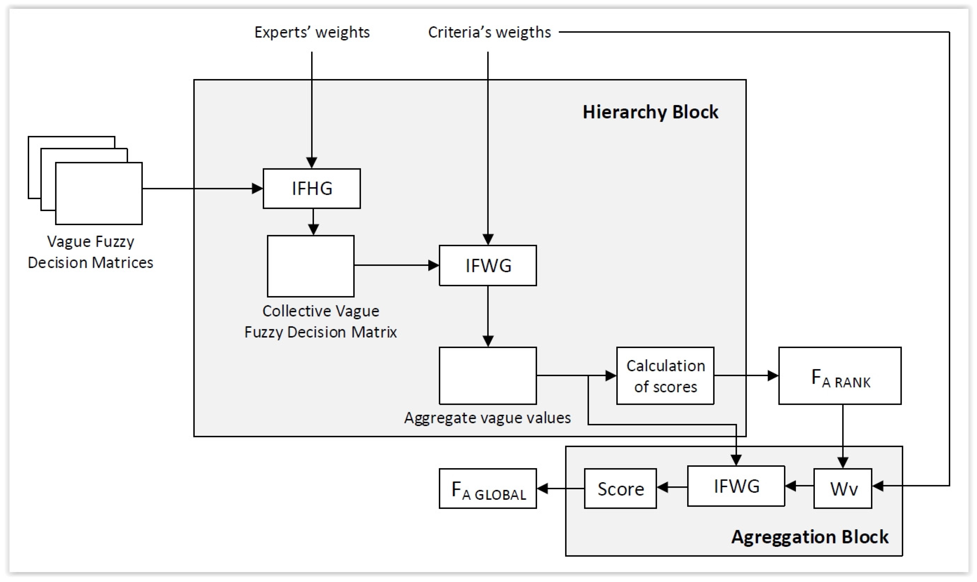
  • Making use of a series of operators derived from the Intuitionistic Fuzzy Set concept [62,74], which are applicable to vague numbers as these are essentially intuitionistic fuzzy numbers [63], it is possible to perform an aggregation and a subsequent defuzzification of the vague numbers that compose the previously defined matrices (the Vague Fuzzy Decision Matrix). Such operators, among which the Intuitionistic Fuzzy Weighted Geometric (IFWG) operator, the Intuitionistic Fuzzy Ordered Weighted Geometric (IFOWG) operator, and the Intuitionistic Fuzzy Hybrid Geometric (IFHG) operator [67] are perhaps the most representative, allow us to group all the matrices into a new Collective Vague Fuzzy Decision Matrix, and after that, to generate the Aggregate Vague Values associated with each alternative. Using those values, it is possible to calculate a score for each aggressiveness factor, and thus to determine the hierarchization depending on the value of the weight obtained. The hierarchization will be performed by calculating the scores value of the aggregate vague numbers that represent each aggressiveness factor. These score values will lie within the [−1, 1] interval [75], with “1” indicating that the corresponding aggressiveness factor has to belong to the risk function of each of the input variables.

Implementation of the Hierarchization Process

To expand on point no. 3 above, obtaining an effective hierarchization requires a prior definition of the relationship between the criteria and the aggressiveness factors, these being expressed as vague values. These values will be later defined as intuitionistic values, following the relationships indicated in the equations shown in Table 3.
If we assume that μ A and v A are respectively the membership and non-membership functions associated to intuitionistic set A, and that t A and f A are, respectively, the truth-membership function and the false-membership function of the vague set A [62], considering the work by [63], we may claim that the fuzzy vague set AV is an intuitionistic set itself. We will employ in this article the vague set notation when expressing the different intuitionistic aggregators that will be used in the development of the methodology.
Once all the vague values are available, they are applied with different intuitionistic operators expressed using vague diffuse set notation. First, the Intuitionistic Fuzzy Hybrid Geometric (IFGH) operator is applied—see Equation (1) [67], where a ˜ = [ t a ˜ , 1 f a ˜ ] is an intuitionistic fuzzy value and ω = ( ω 1 , ω 2 , , ω n ) T is the weights vector—on the Vague Fuzzy Decision Matrices, taking into account the weights from the experts, which allows us to determine the Collective Vague Fuzzy Decision Matrix, i.e., the matrix that conjointly represents the valuations given by the different experts.
IFHG ω , w a ˜ 1 , a ˜ 2 , , a ˜ n = j = 1 n t a ˜ σ ( j ) w j , j = 1 n 1 f a ˜ σ ( j ) ω j
Later, the Intuitionistic Fuzzy Weighted Geometric (IFWG) operator is applied—see Equation (2) [67], where a ˜ = [ t a ˜ , 1 f a ˜ ] is an intuitionistic fuzzy value and ω = ( ω 1 , ω 2 , , ω n ) T is the weights vector—and this, operating on the Collective Vague Fuzzy Decision Matrix and taking into account the criteria, allows us to determine the Aggregate Vague Values.
IFWG ω a ˜ 1 , a ˜ 2 , , a ˜ n = j = 1 n t a ˜ j ω j , j = 1 n 1 f a ˜ j ω j
Finally, from these Aggregate Vague Values, it is possible to calculate the score for each aggressiveness factor—see Equation (3) [67]—and determine their hierarchization.
S ( a ˜ ) = t a ˜ f a ˜

2.2.3. Determination of the Global Aggressiveness Factor

In this sub-section, the aggregation block from Figure 1 is described, which is shown in more detail in Figure 3.
In the same way, by applying one of the formerly mentioned operators (IFWG, for example), it is possible to achieve the aggregation of the aggressiveness factors: the Global Aggressiveness Factor is obtained then through the use of an operator and the subsequent calculation of its score as a defuzzification step.
To apply IFWG, it is necessary to define a weighting vector (Wv) associated with the aggressiveness factors. Such a weighting vector is derived from the weighting vector of the input variables—previously normalized to a [0, 10] scale—once it has been weighted by means of the power using the value associated with the normalization of the aggressiveness factor hierarchy, in a [0, 10] interval, to highlight the influence of the hierarchy of factors on the criteria weights. This normalization to the [0, 10] interval aims to homogenize both the power and the exponent of the weighting vector, highlighting the influences of the different aggressiveness factors. The score value will be determined by the last vague number aggregated from the list of vague numbers determining the hierarchy of aggressiveness factors, lying within the [−1, 1] closed interval. This is because a score value of “1” would mean that the aggressiveness factors are collectively prone to belong to the risk functions of their input variables, and vice versa, and a score value of “−1” would mean that the risk factors are prone to not belonging to the risk function of their input variables.

2.2.4. Capture and Processing of the Machining Process Audio Signals

The system features a series of characteristic audio signals, representative of the different machining conditions, and these are stored in a data base. When a CNC machine is in operation, the capturing of the emitted sounds is carried out with the help of a microphone. The resulting captured audio signal files and their equivalents from the data base are then processed.
The process for quantifying the audio signals used in the methodology proceeds according to four steps:
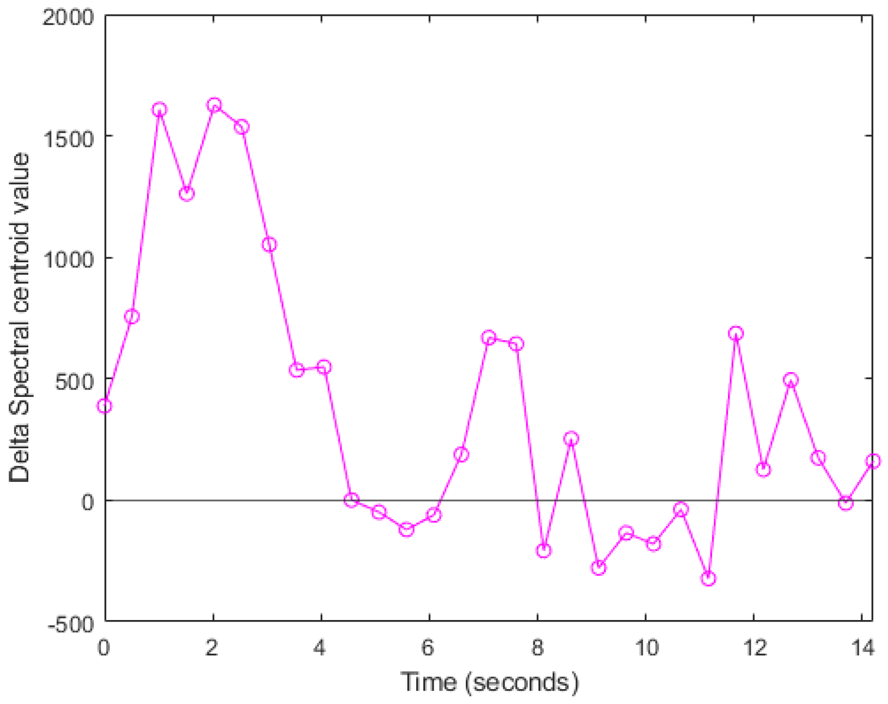
  • Step 1—The centroids are calculated for the audio signal spectrum every 0.5 s, both for the current audio sample and for the reference sample stored in the database;
  • Step 2—The difference function between the centroid functions associated with each audio sample is determined;
  • Step 3—Once the centroid graphs for the spectra of both signal samples have been established, it is possible to calculate the difference between them, and later to determine the area associated with a given time interval;
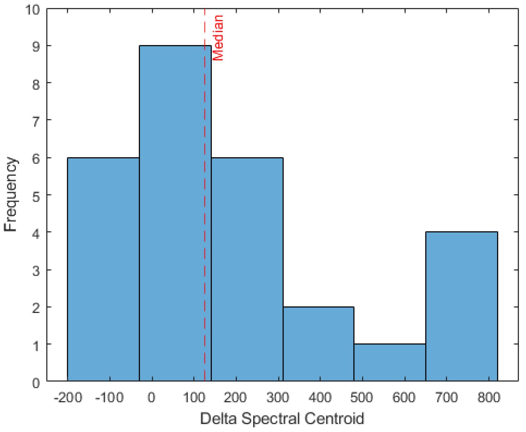
  • Step 4—After that, the median value is calculated for the different areas obtained, and a value is determined that represents the distortion associated with the spectrum, taking into account that the ideal median value should be close to zero.

2.2.5. Second Expert System

Subsequently to the first one, the second expert system aims to determine the characterization of the tool risk by taking into consideration the results of the audio processing and the Global Aggressiveness Factor.
Just as for the first expert system, the knowledge base here will be composed of the whole set of declarative rules representing the expertise and the knowledge of the experts involved in the assessment of the machining tools’ conditions. In this case, the system combines three types of input variables. On the one hand, the Global Aggressiveness Factor derived from the previous calculation block, and on the other hand, both the interpretation of the variable associated with the machine sound and a corrective variable that complements and corrects the final results. In this case, determining the form in which the different variables are combined is a particularly complex task, wherein it is unavoidable that the experts might differ. Because of this, the knowledge base must contain a variable, previously described as a “corrective”, which allows for reducing the uncertainty involved in the knowledge representation, and thus improving the reliability of the prediction. As an example of the declarative rules used in the knowledge base of the second expert system, the following can be mentioned: IF (Global_agressiveness_factor is Low) AND (Audio_delta_area is Low) then (Tool_risk is Low); IF (Global_agressiveness_factor is Low) AND (Audio_delta_area is Medium) then (Tool_risk is Low); IF (Global_agressiveness_factor is Low) AND (Audio_delta_area is High) then (Tool_risk is High). It is relevant to point out that the reinforcement variable is not taken into account in the first iterations of use, as this is incorporated later to allow for weighting the importance of the different rules. This rule set will be later incorporated into the inference mechanism, allowing us in this way to collect the final result.
In this case, the inference engine is indicated as the “Fuzzy 2” block in Figure 1. It is in charge of the information derived from the audio processing operation—the median value of the difference in the areas of the centroids in the frequency spectrum—and from the recollection of the general process conditions, comprehended as the previously calculated Global Aggressiveness Factor. The output of the Mamdani-type [69,70,71,72] inference engine, after deffuzzification, produces a factor named the Tool Risk, which is associated with a decrease in the tool lifespan. The characteristics of this inference system are similar to those described in 2.2.1., “First expert system”, defining input and output variables by means of trapezoidal membership functions, implicated with an AND-operator and aggregating the consequents with a disjunctive approach [72].
The inference mechanism used in the second expert system is similar to the modus ponens deductive tautology that was previously described and used in the first expert system.
Just as in the case of that first expert system, now, for the second expert system, Table 4 gathers the initial configuration of the inference system used in the calculation of the Tool Risk value.

2.2.6. Strategy for the Reinforcement of the Knowledge Base

Within the wide scope of artificial intelligence, the “reinforcement” term is usually associated with a Machine Learning-related learning approach, a paradigm of statistical intelligence numerical models. In symbolic intelligence, “learning” is not a usual term because reasoning capabilities are associated with inference processes that are based on symbolic representations of reality, i.e., the knowledge base implemented by means of logical rules. However, the evolution and modification of this knowledge base implies a learning process, not just in a statistical but in a symbolic context. This point is intended to complement the expert systems with reinforcement strategies applied to their knowledge base, that is, analyzing and understanding the results obtained in order to propose and modify both the logical structure of the rules and their influence within the inference engine. Therefore, in this sub-section, the “Reinforced Fuzzy” block from Figure 1 is described. In this case, the expert (i.e., someone with a profound knowledge of the tool, the machine and its behavior), depending on the circumstances observed in the machining process and based on their expertise, will be able to assess to what degree the Tool Risk value obtained as an output of the second inference system represents the actual condition of the tool and the machine. Such qualitative valuation is fuzzified and processed by a new inference engine of the Mamdani type [69,70,71,72], in this case depicted as the third block shown in the diagram. The output of this last inference engine produces a correction factor that is fed back into the second engine, allowing it to correct its behavior by modifying or adjusting the relevance of the production (declarative and inference) rules in the knowledge base. This adjustment makes more sense with the intensive use of the methodology, so that as it is applied more frequently, the expert valuation of the collected data will become more accurate each time, and consequently, it will be able to modify the results of the second inference system, and therefore the calculation of the Tool Risk value.

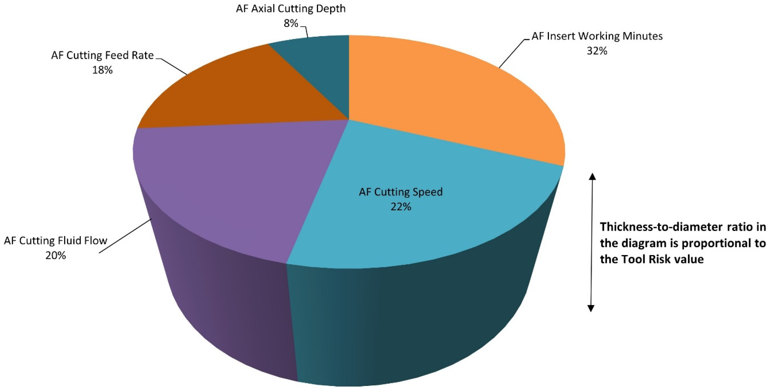
2.2.7. Calculation of the Diagram and Interpretation of the Risk

Using the Tool Risk value and the hierarchy of the different aggressiveness factors associated with each of the variables of the previously determined process, it is possible to plot a 3D sector diagram in which the relative area of each of the sectors represents the proportion of the risk associated with each of the process variables, while its thickness represents the Tool Risk as a function of the diagram’s diameter. Through the interpretation of this diagram, it is possible to determine the process variables that must be changed to increase the machining tool’s lifespan.
To ease the interpretation of the diagram, and considering the obtained Tool Risk value, it is necessary to define a set of thresholds that might suggest to the users of the methodology a series of corrective measures, as follows:
  • For Tool Risk values lower than or equal to 60%, i.e., diagram thicknesses smaller than 60% of the diameter of its base, it will be understood that the work conditions do not involve relevant excesses in tool wear, and therefore there is little effect on the tool’s lifespan;
  • For Tool Risk values in the 60–80% range of the diagram’s base diameter, it will be understood that the work conditions should be checked, as they might produce the early wear of the tool and a certain shortening of its lifespan;
  • For Tool Risk values equal to or above 80%, it will be understood that the work conditions are inadequate, and must be changed at once.
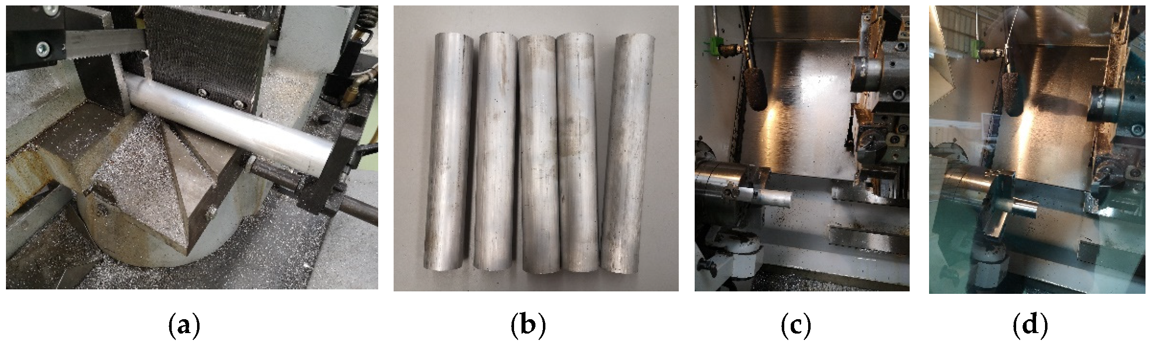
The interpretation of the diagram will always require the participation of the users of the methodology.

3. Case Study

A concept test is presented in this section, aiming to show the operation of the proposed methodology by means of a simple example of use. It is not intended to validate the methodology, but rather to assess its appropriateness for use in a real work environment as a predictor of the machining tool’s condition. To that end, it starts from a set of data obtained from a series of experiments made using a lathe equipped with two tool inserts, each one of which with different wear levels. One of these inserts—its data will be used as a reference—is brand new with zero use, while the other one—which will be analyzed in this case study—has been used for some time, cumulating about 30 work minutes. Next, in Table 5, the process’ general parameters are presented for this case study. It is relevant to point out that, depending on the purpose and the operation to be performed, the workshop experts will have to modify them, with this having no influence at all on the proposed methodology itself.
The experiments consisted of 60 mm-length round-turning operations performed on 40 mm-diameter and 240 mm-length aluminum stock bars, using, as already mentioned, the machining parameters and tools indicated in Table 5. Figure 4 shows several pictures of the experiments, from the preparation of the material, by way of its mounting on the machine, to the final machined part.
Figure 4a shows the cutting of the stock bars for the tests. Figure 4b shows the cut metal stocks. Figure 4c shows the machining cabin with the metal stock placed in the lathe chuck prior to being machined. Finally, Figure 4d shows the machined part, after undergoing several round-turning passes.
Regarding the cutting fluid’s flow parameter, a choice was made to remove its scale, so that the minimum flow equaled 0% and the maximum flow equaled 100%.
The machined material type was aluminum. As has been previously mentioned, the characterization of the material was carried out using its machinability parameter. Said parameter will be within the [1,5] range, with 1 corresponding to a material not recommended to be machined and 5 to a material with excellent properties for machining. For aluminum alloys, machinability values between 4 and 5 are generally obtained, and because of this, in this case, to demonstrate the operation of the methodology, a mean value of 4.5 was used.

3.1. First Expert System

As was established in the “2.2.1. First expert system” sub-section of the “2.2. Implementation of the methodology” section, first, fuzzification was carried out on the machining process’ general parameters taken from the knowledge base and shown in Table 2.
Figure 5 shows some examples of the modus ponens inference rule used for calculating the aggressiveness factor associated to the cutting speed in the case study. In the first case of Figure 5a, the rule is “IF (Cutting_speed is Low) AND (Machinability is High) THEN (CS-AF is Low)”. As the cutting speed, 150 m/min in this case, belongs to the “low speed” fuzzy set, and the machinability, with a value of 4.5 for aluminum, belongs to the “high machinability” fuzzy set (for more information on the fuzzy sets, see Table 2 and check the definition of the membership functions associated to each input variable of the first expert system), then the rule premises are met, and therefore it can be concluded that the CS-AF is “low”. On the other hand, in the second example of Figure 5b, the rule is “IF (Cutting_speed is Medium) AND (Machinability is High) THEN (CS-AF is Medium)”. As the cutting speed also belongs to the “medium speed” fuzzy set, and the machinability belongs to the “high machinability” fuzzy set, it may be concluded that the CS-AF is “medium”.
Five factors are obtained after the inference process, each of which being associated respectively to each of the general parameters shown in Table 1, with the exception of the material machinability, which is considered a general parameter of the process, as shown in Table 6. In this case, a choice was made to use aggressiveness factors lying within the [0, 10] range, with, on the one hand, a 0 value indicating the absence of aggressiveness in the effect of that factor on the tool’s lifespan, and on the other hand, a value of 10 corresponding to the maximum degree of aggressiveness.

3.2. Hierarchization of the Aggressiveness Factors

Once the different aggressiveness factors associated with each of the general parameters of the process have been obtained (A1: Cutting Speed Aggressiveness Factor, A2: Cutting Feed Rate Aggressiveness Factor, A3: Axial Cutting Depth Aggressiveness Factor, A4: Cutting Fluid Flow Aggressiveness Factor and A5: Insert’s Cumulated Work Time Aggressiveness Factor), we proceed to their hierarchization by taking into account a set of criteria and the opinions of an expert team, with the goal of determining those factors that have a higher impact on the tool lifespan (for more information, see the “Implementation of the Hierarchization Process” sub-section). Additionally, aiming to ease the calculations associated with the hierarchization of the aggressiveness factors, an application has been developed in MATLAB® R2020b including a fully functional interface, which allows us to input the data and to perform the calculations associated with the determination of the hierarchy in an easy and intuitive way.

3.2.1. Calculation of the Diagram and Interpretation of the Risk

In this particular case, there will be five criteria/attributes (C1: Cutting Speed, C2: Cutting Feed Rate, C3: Axial Cutting Depth, C4: Cutting Fluid Flow and C5: Insert’s Cumulated Working Time) and two experts (E1 and E2). Later, each expert will perform valuations of the alternatives, taking into account the different criteria. Table 7 and Table 8 show the Vague Fuzzy Decision Matrices for Expert 1 and Expert 2, respectively.

3.2.2. Definition of the Weights of the Criteria and the Experts

Once the Vague Fuzzy Decision Matrix for each expert has been defined, and before the application of the operators, it is necessary to define the weighting vectors for both the experts and the criteria. In this case, the criteria weighting vector is wc = (0.15, 0.15, 0.2, 0.2, 0.3)T and the experts weighting vector is we = (0.8, 0.2)T. In the case of Expert 1, its weight is 80, a value obtained after calculating the mean value of its self-assessment and the score given to them by the other expert, ( 75 + 85 2 ). In the case of Expert 2, its weight is 20, a value obtained, as in the previous case, by calculating the mean value of its self-assessment and the score given by the other expert, ( 25 + 15 2 ). Regarding the criteria, their weights are determined as the median values of the assessment scores of the different experts regarding the different criteria. There are two experts in this case, so the median equals the mean value. The weights vector proposed by Expert 1 for the different criteria is (10, 10, 25, 20, 35), while the weights vector proposed by Expert 2 is (20, 20, 15, 20, 25), which gives ( 10 + 20 2 , 10 + 20 2 , 25 + 15 2 , 20 + 20 2 , 35 + 25 2 ), that is, the weights vector (15, 15, 20, 20, 30).

3.2.3. Application of Operators

After defining the Vague Fuzzy Decision Matrices and the weights associated with the criteria and the experts, it is time to apply the operators.
First, the Intuitionistic Fuzzy Hybrid Geometric (IFGH) operator is applied on the Vague Fuzzy Decision Matrices, taking into account the weights given by the experts, thus allowing us to determine the Collective Vague Fuzzy Decision Matrix, i.e., the matrix that represents the valuations of the different experts conjointly. Table 9 shows the Collective Vague Fuzzy Decision Matrix obtained after applying that operator.
Next, the Intuitionistic Fuzzy Weighted Geometric (IFWG) operator is applied, which, by operating on the Collective Vague Fuzzy Decision Matrix and taking into account the criteria, allows us to determine the Aggregate Vague Values. These Aggregate Vague Values are shown in Table 10.
Finally, starting with the Aggregate Vague Values, it is possible to calculate the score for each alternative (see Table 11).

3.3. Determination of the Global Aggressiveness Factor

As indicated in Figure 1, once the ranking of the aggressiveness factors has been determined, we calculate the Global Aggressiveness Factor by applying the Intuitionistic Fuzzy Weighted Geometric (IFWG) operator (see Equation (2)) on the Aggregate Vague Values vector. Prior to its application, it is necessary to define the weighting vector, which in this case is obtained from the weights vector of the input variables (after it has been normalized to a [0, 10] scale) that has been weighted by means of the power using the value associated with the normalization of the aggressiveness factors hierarchy in a [0, 10] interval, to highlight the influence of the hierarchy of the factors on the criteria weights. Thus, the weighting vector obtained is wg = (0.0592, 0.0500, 0.0430, 0.0931, 0.7547)T.
Once the weighting vector has been defined, and after applying IFWG to the Aggregate Vague Values, shown in Table 10, it is possible to determine the Global Aggressiveness Factor, which shows a value of 0.7018.

3.4. Capture and Processing of the Machining Audio Signals

In a similar way to the previously described stages, it is possible to carry out the management and processing of the audio signals captured during the machining process.
Figure 6 shows a graph allowing us to compare the centroids of the spectrum of the audio signal registered every 0.5 s, for the insert with 30 cumulated work minutes and the one with 0 min, respectively.
Once the graphs of the centroids of the spectra of both signals have been calculated, it is possible to calculate their difference function (see Figure 7), and later to determine the area associated with a specific time interval. After that, the median value is calculated for the different areas obtained for each second, so that a value is obtained that represents the distortion associated with the spectrum, as the ideal median value should be close to zero.
In this case, a median value of 125.068 is obtained. Figure 8 shows a histogram representing the distribution of the difference between areas and its median value, this last parameter being represented by the dashed line.

3.5. Second Expert System

Following the determination of the Global Aggressiveness Factor and the median value, it is possible to determine the Tool Risk value after performing an inference process.
Just as for the first expert system, Figure 9 illustrates the modus ponens mechanism involved in the second expert system. The rule to be evaluated is “IF (AF_Global is High) AND (Delta_area_centroid is Low) THEN (Tool_risk is Medium)”. In this case, the Global Aggressiveness value is 0.7018, which belongs to the “high” aggressiveness factors set, while the median value of the area increment is 125.068, which belongs to the “low” area increment median values set. As the premise is met, it may be concluded that the Tool Risk is “medium”.
This Tool Risk value lies within the [0, 100] interval, and it is associated with a reduction in tool lifespan.
In this case, a risk value of 50 has been obtained.

3.6. Strategy for the Reinforcement of the Knowledge Base

In the case of the example shown, as the data refer to the first application cycles of the methodology, the reinforced fuzzy process is not yet able to show a determinant influence on the results, because the user still does not have access to a large variety of results that would help them make an appropriate decision.

3.7. Calculation of the Diagram and Risk Interpretation

A risk value of 50 is obtained in this case, represented as the diagram’s thickness, a moderate value that invites us to consider that the current work conditions are acceptable.
It is also possible to carry out an interpretation of the previously obtained hierarchy of aggressiveness factors via the proportional representation of their scores using a sector diagram, which can be seen in Figure 10. It can be observed in this case that one of the most relevant aspects is the cumulated work time of the tool, meaning that if any defects are observed in the parts, even if a high risk level is not obtained, it might be necessary to replace the tool.

3.8. Validation

In order to validate the outcomes of the methodology, we propose to compare the results derived from its application with those other obtained by means of direct assessments made by experts from the relevant field of study. This involves determining the influence of different parameters on the machining tool’s lifespan, so a collection of questions is posed to five machining experts, asking them to score as a percentage (0–100%) the respective impacts of the parameters, taking into account the sound of the machining process itself with the different inserts, and analyzing the values of the corresponding machining parameters. Table 12 shows the scores given by the different experts on a 0–100 scale, together with the estimation derived from the application of the methodology.
In order to determine the variation between the methodology’s results and the proposals made by the different experts, the root-mean-square error value was calculated for each expert [76,77], and the obtained values can be seen in Table 13.
The RMSE mean value has been calculated from the RMSE values shown in Table 13, with a resulting figure of 7%. This value indicates that a mean value separation of 7% exists between the experts’ scores and those determined by the methodology. Assuming a 7% degree of uncertainty in the results implies that the methodology will offer admissible results in 93% of all cases, all of these being in the initial operation stages of the methodology and without using reinforcement to correct the inferences of the second expert system. Thus, considering the few iterations employed in the operation of the expert system, together with the variability that is inherent to the machining process, the results can be considered as encouraging. It must be considered that the difficulty does not lie as much in the prediction (that is, in the coincidence of the experts’ and methodology’s judgments) as in the replicability of the subjective reasoning involved in that methodology.

4. Discussion

The prevention of failure in machine tools by controlling all those aspects that may, either directly or indirectly, influence their behavior has produced its own field of study. The costs associated with mistakes, either forced or not, in the characteristic elements of the machining process are high enough to conclude that effective and predictive management processes are required. In this paper, a methodology is conceptualized that combines qualitative and quantitative data associated with the behavior and operation of a machine to generate alerts aimed to prevent failures or to correct harmful trends, pointing to the potential original cause of the problem. To do so, a set of expert systems has been defined, within the theoretical definition framework of a decision-support methodology, that act as elements by which the information is processed in order to generate a set of decision factors. These factors are then hierarchized and combined with the quantitative data obtained from a comparative analysis of the sound emitted by the machine in operation, in order to obtain a risk value associated with its operation. With this risk and the hierarchy of factors, recommendation graphs are generated that make it possible to predict failure trends and to prevent errors. Aside from the satisfactory results obtained in the case study, evaluated by calculating the RMSE value, and the indubitable usefulness of the methodology, its contributions must be analyzed from the viewpoint of its basic constitutive elements, as well as of its abilities to manage uncertainty, which will be commented on next.
  • Expert systems: The use of expert systems, with respect to other prediction models used in artificial intelligence, such as machine learning or deep learning algorithms, and even classic statistical inference models, presents a differential advantage resulting from the use of symbolic reasoning for the creation of its knowledge base and its inference mechanism. In the face of normal computational reasoning, based on the identification of the statistical relevance of the collected data, and implemented by means of different algorithms such as random forest, Naïve Bayes, and different types of neural networks and evolutional programming approaches, symbolic reasoning possesses the ability to model knowledge based on symbols, such as in common language. On the other hand, the conceptualization of expert systems facilitates the diversification of the knowledge derived from information sources—in this case experts from the machining field—as well as generalizing its formalization [78], which allows and simplifies the appropriate use of machines by staff members possessing different skill and expertise levels in the field of study. This will result in a reduction in the machine’s dependence on its operator’s skills, and in the incorporation of external expertise and knowledge into the control of the machining process. Expert systems also help to reduce the uncertainty that is inherent to the machine condition assessment process itself, both the random or epistemic, and that associated to the vagueness that is present in human language [79]. It is of interest to mention that the inference engine used by the expert systems could be a different one, in this way making possible the incorporation of other engines or algorithms, which endows it with greater versatility and adaptability.
  • Vague fuzzy sets: The use of multi-criteria models is common in decision-making stages, where a decision-maker must determine the ranking of a collection of alternatives according to some criteria in order to select the best option. As was already mentioned in the sub-section “1.3. Hierarchization processes”, new approaches have been developed in the last few decades incorporating new abilities that allow for solving some of the limitations that affect the “classic” models. In this work, a choice was made for the use of vague fuzzy sets to determine the hierarchization of the factors presenting a larger impact on the tool’s lifespan, which allows us to construct an error verification protocol that is specific to each machine. The use of this approach allows for not only limiting the random and epistemic [79,80] uncertainty in the scoring process, but also for controlling the hierarchization process itself [67]. Even if it is true that other multi-criteria methods exist that allow one to manage uncertainty in an implicit way, the choice of using vague fuzzy numbers is a novelty in the field of study.
The methodology proposed here will integrate the whole of the process described above, plus all the input and output data. With that, an effective means of support will be provided to the decision-making process carried out by the machine operators, who will not need to be machining experts to be able to make predictive and corrective decisions about its behavior.
Even if the methodology is still at the concept-development stage, it is expected that it will be very useful for improving work management in machining processes.
In the validation stage of the results derived from the case study, it was observed that there were no large differences between the recommendations made by the methodology and those proposed by experts from the machining field. It is important to highlight that the recommendations proposed by the methodology are not required to match those proposed by said experts, and this does not invalidate the use of the methodology at all. The methodology incorporates a reinforcement module that will make it possible, as the methodology is extensively used, to modulate its behavior, adapting it to the needs and the particularities of a specific machine, thus extending its usefulness and validity. Both the discrepancies and the coincidences in the recommendations are beneficial, as in the first case new knowledge is incorporated into the methodology to adapt it to a specific machine, and in the second case the trust in the system is reinforced. The reinforcement strategy incorporates dynamism into the second expert system’s knowledge base, allowing the operators themselves, or any other expert using the machine, to modify the representation of the logical rules that model the behavior of the machining process, and even the inference process itself. The system is provided with specific learning capabilities that are subject to the knowledge of the experts, which, despite potentially not obtaining acceptable results in the first cycle of the methodology, may after extended use result in a knowledge representation that is sufficiently diverse, heterogeneous and variable.
Its objective is not, in any case, to approximate the experts’ and the methodology’s judgments, but to approximate their reasoning. It is about emulating the experts’ reasoning by means of symbolic models implemented within expert systems. Once that is achieved, those judgements should coincide, provided that the expert and the methodology use the same starting information. Furthermore, after a sufficiently large number of iterations, the methodology, by emulating the reasoning process, might produce more reliable and accurate judgments than a human expert, because it would always objectively consider the criteria, and it should not introduce any bias in its interpretations other than that associated with the generation of rules.
The reliability of the data fed to the methodology, a key factor in any predictive methodology, might introduce a challenge, mainly in terms of the sound signals emitted by the machining tool. The sound signals produced when the tool is cutting are very useful, and are a good indicator of the tool’s condition; however, there are other sound sources inside the machining cabin, such as the motors/spindles driving the machine, which could affect those signals. The representative capability of the interpretative variable associated with these sound signals, and the experts’ assessments, will make the fuzzy models and the vague numbers even more useful. Even if it could be challenging to create membership functions for interpretative variables, its success in this and its facilitation of the ongoing review of the results derived from its application makes the methodology robust compared to the imperfection of the data representation model.

Relevance to the Field of Study

The use of systems aimed at tool condition monitoring is usual practice in the machining field. One can commonly observe in this field the use of different data management and processing approaches, many of them using artificial intelligence-related techniques. It is precisely the combination of expert system approaches with multi-attribute hierarchization methods that will allow us to increase the usefulness and the novelty of the proposed methodology in the making of decisions associated with the machine. Not only is it novel in the field of study, but the tested robustness of the use of expert systems combined with other approaches will also allow us to characterize the knowledge associated with the operation of the machining equipment. Table 14 shows a formal benchmarking of different approaches that can be found in the current literature with respect to the one proposed in this work, considering five comparison criteria: the efficiency (defined as the reliability of the results, associated to the management of uncertainty), the scalability (defined as the characteristic related to the ability to add or remove calculation elements to/from the system), the inference (related to the ability of the system to use symbolic reasoning), the learning (related to the ability to learn and incorporate new knowledge), and finally the adaptability (defined as the ability to use the method in the monitoring of other machine models).
Given the analysis results shown in Table 14, it is clear that almost none of the studied systems makes use of symbolic reasoning, except for those using ANFIS that hybridize it with computational processing. Before the proposed system, all those analyzed systems required a training process, for which it is necessary to have available a collection of labeled starting data, which are not strictly needed when working with expert systems. The proposed system is the only one that satisfies all the established criteria, which justifies its novelty, reliability and contribution to the field of study.

5. Conclusions

The proposed methodology shows promising application potential to the field of machining tool condition monitoring. It allows for predicting the influence of the different machine operation parameters, thus supporting the decision processes as regards handling and usability. Further to its conceptualization as a decision-support system grounded in the use of expert systems and hierarchization systems based on vague fuzzy numbers, the following differentiating features associated with the developed methodology could be highlighted:
  • It allows one to evaluate the machine’s condition, addressing the different qualitative and qualitative factors that are associated with its usual operation and failure, this being of help to its operators, regardless of whether they are experts or not;
  • It reduces the issues associated with a late/premature tool change, which might result in excessive costs to the company, as well as in other potential losses or damages;
  • It establishes a standard tool condition evaluation process.
Despite all this, it is necessary to mention that, at this moment, the methodology is still in its prototype stage, and still needs optimization, for which it will be necessary to develop a full user graphical interface and to perform intensive validation in real industry environments.
Future works will address not only the software of the proposed methodology, but also extensive pilot tests. It will be then verified in practice whether the presented theoretical development shows actual usefulness, allowing us to assess the time savings, and therefore the cost savings, involved in the management of machining equipment’s and tools’ lifespans.

Author Contributions

Conceptualization, M.C.-G. and A.C.-C.; methodology, A.C.-C. and J.-B.B.-R.; investigation, M.C.-G., A.C.-C., J.-B.B.-R., J.C.-P. and A.P.; software, M.C.-G.; resources, M.C.-G.; validation, M.C.-G., A.C.-C., J.-B.B.-R. and J.C.-P.; writing—original draft preparation, M.C.-G., A.C.-C. and J.C.-P.; writing—review and editing, J.C.-P., J.-B.B.-R. and A.P.; supervision, M.C.-G., J.C.-P. and A.P. All authors have read and agreed to the published version of the manuscript.

Funding

This research received no external funding.

Institutional Review Board Statement

Not applicable.

Informed Consent Statement

Not applicable.

Data Availability Statement

The data presented in this study are available on request from the corresponding authors.

Acknowledgments

M.C.-G. is grateful to Consellería de Educación, Universidade e Formación Profesional e Consellería de Economía, Emprego e Industria da Xunta de Galicia (ED481A-2020/038) for his pre-doctoral fellowship. The authors would like to thank Alfonso Covela Quintela from the Department of Design in Engineering of the University of Vigo for the help provided to perform the laboratory experiments. M.C-G. would like to special thank Engineer Rubén Álvarez Veloso for his expertise and assistance in the early stages of this work.

Conflicts of Interest

The authors declare no conflict of interest.

Abbreviations

AIArtificial intelligence.
AFAggressiveness factor.
Specific Aggressiveness Factors
AC-AFAxial Cutting Depth Aggressiveness Factor.
CFR-AFCutting Feed Rate Aggressiveness Factor.
CFF-AFCutting Fluid Flow Aggressiveness Factor.
CS-AFCutting Speed Aggressiveness Factor.
Insert-AFInsert’s Cumulated Work Time Aggressiveness Factor.
CNCComputer Numerical Control.
IFHGIntuitionistic Fuzzy Hybrid Geometric.
IFOWGIntuitionistic Fuzzy Ordered Weighted Geometric.
IFWGIntuitionistic Fuzzy Weighted Geometric.
OWGOrdered Weighted Geometric.
WGWeighted Geometric.

References

  1. Saptaji, K.; Gebremariam, M.A.; Azhari, M.A.B.M. Machining of Biocompatible Materials: A Review. Int. J. Adv. Manuf. Technol. 2018, 97, 2255–2292. [Google Scholar] [CrossRef]
  2. Santos, M.C.; Machado, A.R.; Sales, W.F.; Barrozo, M.A.S.; Ezugwu, E.O. Machining of Aluminum Alloys: A Review. Int. J. Adv. Manuf. Technol. 2016, 86, 3067–3080. [Google Scholar] [CrossRef]
  3. Hovsepian, P.E.; Luo, Q.; Robinson, G.; Pittman, M.; Howarth, M.; Doerwald, D.; Tietema, R.; Sim, W.M.; Deeming, A.; Zeus, T. TiAlN/VN Superlattice Structured PVD Coatings: A New Alternative in Machining of Aluminium Alloys for Aerospace and Automotive Components. Surf. Coat. Technol. 2006, 201, 265–272. [Google Scholar] [CrossRef]
  4. Byrne, G.; Dornfeld, D.; Inasaki, I.; Ketteler, G.; König, W.; Teti, R. Tool Condition Monitoring (TCM)—The Status of Research and Industrial Application. CIRP Ann.—Manuf. Technol. 1995, 44, 541–567. [Google Scholar] [CrossRef]
  5. Ji, W.; Wang, L. Industrial Robotic Machining: A Review. Int. J. Adv. Manuf. Technol. 2019, 103, 1239–1255. [Google Scholar] [CrossRef] [Green Version]
  6. Zhou, C.; Guo, K.; Yang, B.; Wang, H.; Sun, J.; Lu, L. Singularity Analysis of Cutting Force and Vibration for Tool Condition Monitoring in Milling. IEEE Access 2019, 7, 134113–134124. [Google Scholar] [CrossRef]
  7. Kurada, S.; Bradley, C. A Review of Machine Vision Sensors for Tool Condition Monitoring. Comput. Ind. 1997, 34, 55–72. [Google Scholar] [CrossRef]
  8. Ambhore, N.; Kamble, D.; Chinchanikar, S.; Wayal, V. Tool Condition Monitoring System: A Review. Mater. Today Proc. 2015, 2, 3419–3428. [Google Scholar] [CrossRef]
  9. Rehorn, A.G.; Jiang, J.; Orban, P.E. State-of-the-Art Methods and Results in Tool Condition Monitoring: A Review. Int. J. Adv. Manuf. Technol. 2005, 26, 693–710. [Google Scholar] [CrossRef]
  10. Mohanraj, T.; Shankar, S.; Rajasekar, R.; Sakthivel, N.R.; Pramanik, A. Tool Condition Monitoring Techniques in Milling Process-a Review. J. Mater. Res. Technol. 2020, 9, 1032–1042. [Google Scholar] [CrossRef]
  11. Serin, G.; Sener, B.; Ozbayoglu, A.M.; Unver, H.O. Review of Tool Condition Monitoring in Machining and Opportunities for Deep Learning. Int. J. Adv. Manuf. Technol. 2020, 109, 953–974. [Google Scholar] [CrossRef]
  12. Ruitao, P.; Pang, H.; Jiang, H.; Hu, Y. Study of Tool Wear Monitoring Using Machine Vision. Autom. Control Comput. Sci. 2020, 54, 259–270. [Google Scholar] [CrossRef]
  13. Dou, J.; Xu, C.; Jiao, S.; Li, B.; Zhang, J.; Xu, X. An Unsupervised Online Monitoring Method for Tool Wear Using a Sparse Auto-Encoder. Int. J. Adv. Manuf. Technol. 2020, 106, 2493–2507. [Google Scholar] [CrossRef]
  14. Fong, K.M.; Wang, X.; Kamaruddin, S.; Ismadi, M.Z. Investigation on Universal Tool Wear Measurement Technique Using Image-Based Cross-Correlation Analysis. Meas. J. Int. Meas. Confed. 2021, 169, 108489. [Google Scholar] [CrossRef]
  15. Teti, R.; Jemielniak, K.; O’Donnell, G.; Dornfeld, D. Advanced Monitoring of Machining Operations. CIRP Ann.—Manuf. Technol. 2010, 59, 717–739. [Google Scholar] [CrossRef] [Green Version]
  16. Sick, B. On-Line and Indirect Tool Wear Monitoring in Turning with Artificial Neural Networks: A Review of More than a Decade of Research. Mech. Syst. Signal Process. 2002, 16, 487–546. [Google Scholar] [CrossRef]
  17. Shi, X.; Wang, R.; Chen, Q.; Shao, H. Cutting Sound Signal Processing for Tool Breakage Detection in Face Milling Based on Empirical Mode Decomposition and Independent Component Analysis. JVC/J. Vib. Control 2015, 21, 3348–3358. [Google Scholar] [CrossRef]
  18. Burstein, F.; Holsapple, C.W. Handbook on Decision Support Systems 1; Springer: Berlin, Germany, 2008. [Google Scholar]
  19. Burstein, F.; Holsapple, C.W. Handbook on Decision Support Systems 2; Springer: Berlin, Germany, 2008. [Google Scholar]
  20. Bonczek, R.H.; Holsapple, C.W.; Whinston, A.B.; Carter, H. Foundations of Decision Support Systems; Academic Press: New York, NY, USA, 1981. [Google Scholar]
  21. Hevner, A.R.; Chatterjee, S. Design Research in Information Systems: Theory and Practice; Springer: New York, NY, USA, 2010; ISBN 978-1-4419-6107-5. [Google Scholar]
  22. Lucas, P.J.F.; van der Gaag, L.C. Principles of Expert Systems; Addison-Wesley: Wokingham, UK, 1991; ISBN 0-201-41640-9. [Google Scholar]
  23. Krishnamoorthy, C.S.; Rajeev, S. Artificial Intelligence and Expert Systems for Engineers; CRC Press: Boca Raton, FL, USA, 1996. [Google Scholar]
  24. Liao, S.H. Expert System Methodologies and Applications-a Decade Review from 1995 to 2004. Expert Syst. Appl. 2005, 28, 93–103. [Google Scholar] [CrossRef]
  25. Sol, H.G.; Takkenberg, C.A.T.; de Vries Robbé, P.F. Expert Systems and Artificial Intelligence in Decision Support Systems. In Proceedings of the Second Mini Euroconference, Lunteren, The Netherlands, 17–20 November 1985. [Google Scholar]
  26. Kumar, Y.; Jain, Y. Research Aspects of Expert System. Int. J. Comput. Bus. Res. 2012, 1, 1–11. [Google Scholar]
  27. Myers, W. Introduction to Expert Systems. IEEE Expert 1986, 1, 100–109. [Google Scholar] [CrossRef]
  28. Buchanan, B.G. Expert Systems: Working Systems and the Research Literature. Expert Syst. 1986, 3, 32–50. [Google Scholar] [CrossRef]
  29. Todd, B.S. An Introduction to Expert Systems; Oxford University Computing Laboratory: Oxford, UK, 1992. [Google Scholar]
  30. Merritt, D. Building Expert Systems in Prolog; Springer: New York, NY, USA, 1989; ISBN 978-1-4613-8913-2. [Google Scholar]
  31. Comesaña-Campos, A.; Casal-Guisande, M.; Cerqueiro-Pequeño, J.; Bouza-Rodríguez, J.B. A Methodology Based on Expert Systems for the Early Detection and Prevention of Hypoxemic Clinical Cases. Int. J. Environ. Res. Public Health 2020, 17, 8644. [Google Scholar] [CrossRef]
  32. Casal-Guisande, M.; Comesaña-Campos, A.; Cerqueiro-Pequeño, J.; Bouza-Rodríguez, J.-B. Design and Development of a Methodology Based on Expert Systems, Applied to the Treatment of Pressure Ulcers. Diagnostics 2020, 10, 614. [Google Scholar] [CrossRef] [PubMed]
  33. Grosan, C.; Abraham, A. Rule-Based Expert Systems. Intell. Syst. Ref. Libr. 2011, 17, 149–185. [Google Scholar] [CrossRef]
  34. Berzal, F. Redes Neuronales & Deep Learning; Independently Published: Granada, Spain, 2018; ISBN 1731265387. [Google Scholar]
  35. Jackson, P. Introduction to Expert Systems; Addison-Wesley Publishing Co., Inc.: Wokingham, UK, 1986. [Google Scholar]
  36. Leondes, C.T. Expert Systems: The Technology of Knowledge Management and Decision Making for the 21st Century; Academic Press: San Diego, CA, USA, 2002; ISBN 978-0-12-443880-4. [Google Scholar]
  37. Hevner, A.R.; March, S.T.; Park, J.; Ram, S. Design Science in Information Systems Research. MIS Q. Manag. Inf. Syst. 2004, 28, 75–105. [Google Scholar] [CrossRef] [Green Version]
  38. Elangovan, M.; Ramachandran, K.I.; Sugumaran, V. Studies on Bayes Classifier for Condition Monitoring of Single Point Carbide Tipped Tool Based on Statistical and Histogram Features. Expert Syst. Appl. 2010, 37, 2059–2065. [Google Scholar] [CrossRef]
  39. Elangovan, M.; Devasenapati, S.B.; Sakthivel, N.R.; Ramachandran, K.I. Evaluation of Expert System for Condition Monitoring of a Single Point Cutting Tool Using Principle Component Analysis and Decision Tree Algorithm. Expert Syst. Appl. 2011, 38, 4450–4459. [Google Scholar] [CrossRef]
  40. Mesina, O.S.; Langari, R. A Neuro-Fuzzy System for Tool Condition Monitoring in Metal Cutting. J. Manuf. Sci. Eng. Trans. ASME 2001, 123, 312–318. [Google Scholar] [CrossRef]
  41. Saglam, H.; Unuvar, A. Tool Condition Monitoring in Milling Based on Cutting Forces by a Neural Network. Int. J. Prod. Res. 2003, 41, 1519–1532. [Google Scholar] [CrossRef]
  42. Li, S.; Elbestawi, M.A. Tool Condition Monitoring in Machining by Fuzzy Neural Networks. J. Dyn. Syst. Meas. Control Trans. ASME 1996, 118, 665–672. [Google Scholar] [CrossRef]
  43. Patange, A.D.; Jegadeeshwaran, R.; Dhobale, N.C. Milling Cutter Condition Monitoring Using Machine Learning Approach. IOP Conf. Ser. Mater. Sci. Eng. 2019, 624, 012030. [Google Scholar] [CrossRef]
  44. Zaloha, V.O.; Zinchenko, R.M.; Honshchyk, A.V. ANFIS Building Methodology for the Task of Cutting Tool Condition Diagnosis Using Matlab Software. Key Eng. Mater. 2014, 581, 466–471. [Google Scholar]
  45. Silva, R.G.; Reuben, R.L.; Baker, K.J.; Wilcox, S.J. Tool Wear Monitoring of Turning Operations by Neural Network and Expert System Classification of a Feature Set Generated from Multiple Sensors. Mech. Syst. Signal Process. 1998, 12, 319–332. [Google Scholar] [CrossRef]
  46. Aralikatti, S.S.; Ravikumar, K.N.; Kumar, H.; Shivananda Nayaka, H.; Sugumaran, V. Comparative Study on Tool Fault Diagnosis Methods Using Vibration Signals and Cutting Force Signals by Machine Learning Technique. SDHM Struct. Durab. Health Monit. 2020, 14, 127–145. [Google Scholar] [CrossRef]
  47. Zuperl, U.; Cus, F.; Balic, J. Intelligent Cutting Tool Condition Monitoring in Milling. J. Achiev. Mater. Manuf. Eng. 2011, 49, 477–486. [Google Scholar]
  48. Lin, X.; Zhou, B.; Zhu, L. Sequential Spindle Current-Based Tool Condition Monitoring with Support Vector Classifier for Milling Process. Int. J. Adv. Manuf. Technol. 2017, 92, 3319–3328. [Google Scholar] [CrossRef]
  49. Hwang, C.L.; Yoon, K. Multiple Attribute Decision Making: Methods and Applications A State-of-the-Art Survey; Springer: Berlin/Heidelberg, Germany, 1981; ISBN 9783642483189. [Google Scholar]
  50. Miller, G.A. The Magical Number Seven, plus or Minus Two: Some Limits on Our Capacity for Processing Information. Psychol. Rev. 1956, 63, 81–97. [Google Scholar] [CrossRef] [Green Version]
  51. Pugh, S. Concept Selection—A Method That Works. In Proceedings of the International Conference on Engineering Design, Heurista, Zürich, Rome, Italy, 9–13 August 1981; pp. 497–506. [Google Scholar]
  52. Pugh, S. Total Design: Integrated Methods for Successful Product Engineering; Addison-Wesley: Wokingham, England, 1991. [Google Scholar]
  53. Saaty, T.L. How to Make a Decision: The Analytic Hierarchy Process. Eur. J. Oper. Res. 1990, 48, 9–26. [Google Scholar] [CrossRef]
  54. Marsh, E.; Slocum, A.H.; Otto, K.N. Hierarchical Decision Making in Machine Design; Technical Report; MIT Precision Engineering Research Center: Cambridge, MA, USA, 1993. [Google Scholar]
  55. Behzadian, M.; Khanmohammadi Otaghsara, S.; Yazdani, M.; Ignatius, J. A State-of the-Art Survey of TOPSIS Applications. Expert Syst. Appl. 2012, 39, 13051–13069. [Google Scholar] [CrossRef]
  56. Opricovic, S.; Tzeng, G.H. Compromise Solution by MCDM Methods: A Comparative Analysis of VIKOR and TOPSIS. Eur. J. Oper. Res. 2004, 156, 445–455. [Google Scholar] [CrossRef]
  57. Brans, J.P.; Vincke, P.; Mareschal, B. How to Select and How to Rank Projects: The Promethee Method. Eur. J. Oper. Res. 1986, 24, 228–238. [Google Scholar] [CrossRef]
  58. Behzadian, M.; Kazemzadeh, R.B.; Albadvi, A.; Aghdasi, M. PROMETHEE: A Comprehensive Literature Review on Methodologies and Applications. Eur. J. Oper. Res. 2010, 200, 198–215. [Google Scholar] [CrossRef]
  59. Dyer, J.S. Maut—Multiattribute Utility Theory. In Multiple Criteria Decision Analysis: State of the Art Surveys; Springer: New York, NY, USA, 2005; Volume 78, pp. 265–295. ISBN 978-0-387-23067-2. [Google Scholar]
  60. Zadeh, L.A. Fuzzy Sets. Inf. Control 1965, 8, 338–353. [Google Scholar] [CrossRef] [Green Version]
  61. Bellman, R.E.; Zadeh, L.A. Decision-Making in a Fuzzy Environment. Manag. Sci. 1970, 17, B-141–B-164. [Google Scholar] [CrossRef]
  62. Gau, W.L.; Buehrer, D.J. Vague Sets. IEEE Trans. Syst. Man Cybern. 1993, 23, 610–614. [Google Scholar] [CrossRef]
  63. Bustince, H.; Burillo, P. Vague Sets Are Intuitionistic Fuzzy Sets. Fuzzy Sets Syst. 1996, 79, 403–405. [Google Scholar] [CrossRef]
  64. Xu, Z. Multi-Person Multi-Attribute Decision Making Models under Intuitionistic Fuzzy Environment. Fuzzy Optim. Decis. Mak. 2007, 6, 221–236. [Google Scholar] [CrossRef]
  65. Atanassov, K. Intuitionistic Fuzzy Sets. In Proceedings of the VII ITKR’s Session, Sofia, Bulgaria, 7–9 June 1983. [Google Scholar]
  66. Atanassov, K.T. Intuitionistic Fuzzy Sets. Fuzzy Sets Syst. 1986, 20, 87–96. [Google Scholar] [CrossRef]
  67. Xu, Z.; Yager, R.R. Some Geometric Aggregation Operators Based on Intuitionistic Fuzzy Sets. Int. J. Gen. Syst. 2006, 35, 417–433. [Google Scholar] [CrossRef]
  68. Xu, Z. An Overview of Methods for Determining OWA Weights. Int. J. Intell. Syst. 2005, 20, 843–865. [Google Scholar] [CrossRef]
  69. Mamdani, E.H.; Assilian, S. An Experiment in Linguistic Synthesis with a Fuzzy Logic Controller. Int. J. Man-Mach. Stud. 1975, 7, 1–13. [Google Scholar] [CrossRef]
  70. Mamdani, E.H. Advances in the Linguistic Synthesis of Fuzzy Controllers. Int. J. Man-Mach. Stud. 1976, 8, 669–678. [Google Scholar] [CrossRef]
  71. Mamdani, E.H. Application of Fuzzy Logic to Approximate Reasoning Using Linguistic Synthesis. IEEE Trans. Comput. 1977, C–26, 1182–1191. [Google Scholar] [CrossRef]
  72. Ross, T.J. Fuzzy Logic with Engineering Applications, 3rd ed.; John Wiley & Sons, Ltd.: Chichester, UK, 2010; ISBN 9781119994374. [Google Scholar]
  73. GRANTA EduPack, Formerly CES EduPack: Materials Education Support | Ansys. Available online: https://www.ansys.com/products/materials/granta-edupack (accessed on 29 December 2020).
  74. Atanassov, K.T. Intuitionistic Fuzzy Sets; Physica-Verlag Heidelberg: Heidelberg, Germany, 1999; ISBN 978-3-7908-2463-6. [Google Scholar]
  75. Chen, S.M.; Tan, J.M. Handling Multicriteria Fuzzy Decision-Making Problems Based on Vague Set Theory. Fuzzy Sets Syst. 1994, 67, 163–172. [Google Scholar] [CrossRef]
  76. Chai, T.; Draxler, R.R. Root Mean Square Error (RMSE) or Mean Absolute Error (MAE)?-Arguments against Avoiding RMSE in the Literature. Geosci. Model Dev. 2014, 7, 1247–1250. [Google Scholar] [CrossRef] [Green Version]
  77. Dubovikov, K. Managing Data Science; Packt Publishing Ltd.: Birmingham, UK, 2019; ISBN 978-1-83882-632-1. [Google Scholar]
  78. Pfeifer, R.; Lüthi, H.-J. Decision Support Systems and Expert Systems: A Complementary Relationship? In Expert Systems and Artificial Intelligence in Decision Support Systems; Springer: Dordrecht, The Netherlands, 1987; pp. 41–51. [Google Scholar]
  79. Thunnissen, D.P. Propagating and Mitigating Uncertainty in the Design of Complex Multidisciplinary Systems; California Institute of Technology: Pasadena, CA, USA, 2005. [Google Scholar]
  80. Herrmann, J.W. Engineering Decision Making and Risk Management; John Wiley & Sons, Inc.: Hoboken, NJ, USA, 2015; ISBN 978-1-118-91933-0. [Google Scholar]
Figure 1. Flowchart of the expert system identifying its 7 main stages.
Mathematics 10 00520 g001
Figure 2. Detail of the hierarchization block.
Mathematics 10 00520 g002
Figure 3. Detail of the hierarchization and aggregation blocks. IFHG refers to the Intuitionistic Fuzzy Hybrid Geometric operator, IFWG to the Intuitionistic Fuzzy Weighted Geometric operator, and Wv corresponds to the weights vector of the aggregation block input variables.
Mathematics 10 00520 g003
Figure 4. Experiment pictures. (a) Parting the stock bars for the experiments. (b) The stocks, ready to be used for the experiments. (c) Machining cabin used in the experiments, with the metal stock bar to be machined. (d) The machined part.
Mathematics 10 00520 g004
Figure 5. Two examples (a,b) of the modus ponens inference rules applied in the case study.
Mathematics 10 00520 g005
Figure 6. Centroids of the spectrum of the machining audio signal registered every 0.5 s.
Mathematics 10 00520 g006
Figure 7. Increment of the spectral centroid.
Mathematics 10 00520 g007
Figure 8. Histogram of the centroid spectrum differences.
Mathematics 10 00520 g008
Figure 9. Example of the modus ponens mechanism in the second expert system.
Mathematics 10 00520 g009
Figure 10. Three-dimensional sector diagram.
Mathematics 10 00520 g010
Table 1. Parameters in the methodology.
Machining Process
-
Process Type
-
Tool
-
General Variables of the Machining Process
Cutting speed
Cutting feed rate
Axial cutting depth
Cutting fluid flow
Insert’s cumulated work time
-
Material to be Machined
Table 2. Configuration of the inference system of the first expert system.
Aggressiveness Factors Associated to the Machining Parameters
Input Data—AntecedentsOutput Data—Consequents
FactorsRangeFactorsRange
Cutting speed (CS)0–1000 m/minCS-AF0–10
Cutting feed rate (CFR)0–1 mm/turnCFR-AF
Axial cutting depth (AD)0–10 mmAD-AF
Cutting fluid flow (CFF)0–100%CFF-AF
Insert’s cumulated work time (insert)0–100 minInsert-AF
Machinability of the material0–5* AF (aggressiveness factor)
* The denomination of the output data indicator consists of two parts. The term on the left of the dash refers to the input variable, while the term on the right of the dash, AF, refers to the aggressiveness factor. For example, CS-AF refers to the cutting speed aggressiveness factor.
Membership functions of the antecedentsMembership functions of the consequents
Cutting speed (CS) Mathematics 10 00520 i002
* In the initial configuration of the inference system, the membership functions of the consequents, that is, of the particular aggressiveness factors for each parameter, are the same, thus only a graph is shown.
Mathematics 10 00520 i001
Cutting feed rate (CFR)
Mathematics 10 00520 i003
Axial cutting depth (AD)Initial configuration
Mathematics 10 00520 i004
  • Fuzzy structure: Mamdani-type.
  • Membership function type: trapezoidal.
  • Defuzzification method: centroid [72].
  • Implication method: MIN.
  • Aggregation method: MAX.
  • Number of fuzzy rules: 45.
Cutting fluid flow (CFF)Subset of the 45 fuzzy rules
  • IF (Cutting_speed is Low) AND (Machinability is Low) THEN (CS-AF is Medium).
  • IF (Cutting_speed is Low) AND (Machinability is Medium) THEN (CS-AF is Low).
  • IF (Cutting_speed is Low) AND (Machinability is High) THEN (CS-AF is Low).
  • IF (Cutting_speed is Medium) AND (Machinability is Low) THEN (CS-AF is High).
  • IF (Cutting_speed is Medium) AND (Machinability is Medium) THEN (CS-AF is Medium).
  • IF (Cutting_speed is Medium) AND (Machinability is High) THEN (CS-AF is Medium).
Mathematics 10 00520 i005
Insert’s cumulated work time (insert)
Mathematics 10 00520 i006
Machinability of the material
Mathematics 10 00520 i007
Table 3. Definition of the intuitionistic fuzzy set and the vague fuzzy set.
Intuitionistic Fuzzy SetVague Fuzzy Set
A I = { x , μ A ( x ) , v A ( x ) x X } A V = { x , [ t A ( x ) , 1 f A ( x ) ] x X }
μ A ( x ) + v A ( x ) 1 t A ( x ) + f A ( x ) 1
Table 4. Configuration of the inference system for the second expert system.
Aggressiveness Factors Associated with the Machining Parameters
Input Data—AntecedentsOutput Data—Consequents
FactorsRangeFactorsRange
Global aggressiveness factor (AF Global)−1 through 1Tool risk0–100
Sound processing and comparison output (Delta_area_centroid)0 5000
Membership functions of the antecedentsMembership functions of the consequent
Global aggressiveness factor (AF Global) Mathematics 10 00520 i009
Mathematics 10 00520 i008
Sound processing and comparison output (Delta_area_centroid)Initial configuration
Mathematics 10 00520 i010
  • Fuzzy structure: Mamdani-type.
  • Membership function type: trapezoidal.
  • Defuzzification method: centroid [72].
  • Implication method: MIN.
  • Aggregation method: MAX.
  • Number of fuzzy rules: 9.
Subset of the 9 fuzzy rules
  • IF (AF_Global is Low) AND (Delta_area_centroid is Low) THEN (Tool_risk is Low).
  • IF (AF_Global is Low) AND (Delta_area_centroid is Medium) THEN (Tool_risk is Low).
  • IF (AF_Global is Low) AND (Delta_area_centroid is High) THEN (Tool_risk is Medium).
Table 5. Process’ general parameters.
Machining Process
ProcessLathe machining
Tool
DesignationDNMG 15 06 08-MR 2025
Insert thickness6.35 mm
Cumulated work time of the old insert30 min
Cumulated work time of the new insert0 min
General Variables of the Machining Process
Cutting speed150 m/min
Cutting feed rate0.2 mm/turn
Axial cutting depth1 mm
Cutting fluid flow0%
Insert’s cumulated work time30 min
Material to be machined
MaterialAluminium
Machinability 4.5
Table 6. Defuzzification of the first inference system. Aggressiveness factors.
Cutting Speed Aggressiveness FactorCutting Feed Rate Aggressiveness FactorAxial Cutting Depth Aggressiveness FactorCutting Fluid Flow Aggressiveness FactorInsert’s Cumulated Work Time Aggressiveness Factor
2.37332.15822.158255
Table 7. Vague Fuzzy Decision Matrix for Expert 1.
E1A1A2A3A4A5
t a ˜ 1 f a ˜ t a ˜ 1 f a ˜ t a ˜ 1 f a ˜ t a ˜ 1 f a ˜ t a ˜ 1 f a ˜
C1110.50.90.50.80.60.80.81
C20.60.9110.60.90.50.70.81
C30.50.80.40.7110.70.80.81
C40.710.60.90.20.3110.81
C50.80.90.60.80.60.70.60.911
Table 8. Vague Fuzzy Decision Matrix for Expert 2.
E2A1A2A3A4A5
t a ˜ 1 f a ˜ t a ˜ 1 f a ˜ t a ˜ 1 f a ˜ t a ˜ 1 f a ˜ t a ˜ 1 f a ˜
C10.910.80.90.60.70.50.90.60.9
C20.40.80.810.710.40.60.40.8
C30.60.70.50.90.910.810.70.9
C40.70.90.70.90.30.50.70.90.60.9
C50.50.70.710.40.90.410.91
Table 9. Collective Vague Fuzzy Decision Matrix.
A1A2A3A4A5
t a ˜ 1 f a ˜ t a ˜ 1 f a ˜ t a ˜ 1 f a ˜ t a ˜ 1 f a ˜ t a ˜ 1 f a ˜
C10.9791.0000.5490.9000.5190.7790.5790.8190.7550.979
C20.5530.8790.9561.0000.6190.9190.4780.6790.6960.956
C30.5190.7790.4180.7360.9791.0000.7190.8370.7790.979
C40.7000.9790.6190.9000.2170.3320.9310.9790.7550.979
C50.7280.8560.6190.8370.5530.7360.5530.9190.9791.000
Table 10. Aggregate Vague Values.
t a ˜ 1 f a ˜
A10.680.89
A20.600.86
A30.520.70
A40.640.86
A50.810.98
Table 11. Hierarchy.
Rank S ( a ˜ )
A50.793
A10.564
A40.495
A20.459
A30.214
Table 12. Estimation of the impact of the different parameters according to different experts.
Aggressiveness Factors
ExpertsCutting SpeedCutting Feed RateAxial Cutting DepthCutting Fluid FlowInsert’s Cumulated Work TimeTotal
Expert A25%5%5%25%40%100%
Expert B20%15%10%20%35%100%
Expert C20%10%10%30%30%100%
Expert D20%15%15%40%10%100%
Expert E30%25%5%20%20%100%
Methodology22%18%8%20%32%100%
Table 13. RMSE for each expert.
ExpertsRMSERMSE Mean Value
Expert A7%7.2%
Expert B2%
Expert C6%
Expert D14%
Expert E7%
Table 14. Benchmarking.
Method/SystemEfficiencyScalabilityInferenceLearningAdaptability
Elangovan et al. [39]The proposed system is based in the use of a decision trees classifier. It does not manage uncertainty.The system is not scalable.It uses statistical inference instead of symbolic reasoning.The system incorporates knowledge in a way that is subsidiary to its classification process.The system could not be easily used for monitoring other machine types, as it would require generating a preliminary dataset.
-----
Mesina and Langari [40]The authors use a neuro-fuzzy system, which does manage uncertainty.The system is not scalable.It uses statistical inference and symbolic reasoning.The system incorporates knowledge by means of a training process.The system could not be easily used for monitoring other machine types, as it would require generating a training dataset.
=-=--
Saglam and Unuvar [41]The proposed system is based in the use of a neural network, which implicitly manages uncertainty in a probabilistic way.The system is not scalable.The system uses statistical inference instead of symbolic reasoning.The system incorporates new knowledge in the process of training the architecture.The system could not be easily used for monitoring other machine types, as it would require a training dataset.
=----
Patange et al. [43]The proposed system is based in the use of decision trees and random forest, which do not manage uncertainty.The system is not scalable.It uses statistical inference instead of symbolic reasoning.The system incorporates knowledge in a subsidiary way to its classification process.The system could not be easily used for monitoring other machine types. It would require a training dataset.
-----
Aralikatti et al. [46]The proposed system is based in the use of machine learning techniques, including the use of the Naïve Bayes classifier. A probabilistic approach is applied to uncertainty control.The system is not scalable.The proposed system uses statistical inference instead of symbolic reasoning.The system incorporates knowledge in a subsidiary way to its classification process.The system could not be easily used for monitoring other machine types. It requires a training dataset.
=----
Lin et al. [48]The proposed system is based on a least squares support vector machine (LS-SVM) classifier. It does not manage uncertainty in the starting data.The system is not scalable.The proposed system uses statistical inference instead of symbolic reasoning.The system incorporates knowledge in a way that is subsidiary to its classification process.The system could not be easily used for monitoring other machine types. It would require a training dataset.
-----
Proposed systemThe proposed system manages uncertainty by means of the use of non-probabilistic approaches.The proposed system is scalable. It is possible to modify the calculation and inference modules.The proposed system uses deductive symbolic reasoning.The system has the capability of modeling and incorporating new knowledge. Additionally, it is provided with a reinforcement module, by means of which it is possible to correct its behavior as the system is being used.The system could easily be adapted to the monitoring of other machine types. It does not require a training process.
Publisher’s Note: MDPI stays neutral with regard to jurisdictional claims in published maps and institutional affiliations.

