
The Effect of Forging Conditions on Final Macrostructure of Slab Ingot from the 55NiCrMoV7 Tool Steel

MATERIAL AND METALLURGICAL RESEARCH, Ltd., Vítkovice, 703 00 Ostrava, Czech Republic
*
Author to whom correspondence should be addressed.
Metals 2021, 11(3), 435; https://0-doi-org.brum.beds.ac.uk/10.3390/met11030435
Submission received: 31 January 2021
/
Revised: 20 February 2021
/
Accepted: 2 March 2021
/
Published: 6 March 2021
(This article belongs to the Special Issue Numerical Modelling in Steel Metallurgy)
Abstract
:The paper presents numerical modelling and an operational experiment to forge a slab ingot P40N from 55NiCrMoV7 tool steel and the procedure for the optimization of its production. The aim of the numerical simulation of forging was to verify the existing procedure of forging a plate from a conventional polygonal 8K forging ingot and a slab ingot with a polygonal shape of P40N surfaces. The effect of the shape of the ingot on the achievement of the required forging reduction and strain after the cross section of the forging of the plate, with final dimensions of approximately 1010 mm width × 310 mm thickness × 5350 mm length, was studied. The results obtained in the operational experiment showed satisfactory qualitative parameters of the steel forging from the slab P40N ingot which were in accordance with the predicted results of numerical simulations. The results indicated that in selected cases the use of a slab P40N ingot instead of the conventional polygonal 8K forging ingot can be considered in the production of certain plate-type forgings.
1. Introduction
The competitive environment is leading ingot steelworks to expand production of forgings with higher added value, which definitively include tool steel forgings. For forgings from approximately 15 to approximately 60 tons it is essential to use quality ingots weighing from 20 to 100 tons and to observe the required chemical composition in view of the very strict requirements for the content of oxygen, sulphur and other elements. In particular, in the case of large forgings, homogeneity and isotropy of properties is required, i.e., the minimum extent of segregations and very low content of non-metallic inclusions. Octagonal polygonal ingots are most often used for forgings. In the case of tool steels, the ingots with a larger chamfer of the ingot wall with a relatively low ratio of the height of the ingot to its mean diameter (H/D) have recently been preferred [1,2,3,4]. These ingot parameters ensure better conditions for charging of molten steel from the hot top to the ingot body during solidification. The result is very small centerline porosity of the ingot. However, the larger diameter of ingots causes a greater central macrosegregation, and thus possible non-homogeneity of mechanical properties of the forged product [5,6,7,8].
In the case of certain types of forging (in particular plates) these macrosegregations can be limited by the use of a slab ingot, which is characterised by the A/B aspect ratio. It is expected that due to the relatively small width of the slab ingot, and thus its faster solidification in comparison to a polygonal ingot of the same mass, the occurrence of macrosegregations in the slab ingot will be smaller than in the polygonal ingot.
Large and heavy forgings are produced by complex open die forging processes on hydraulic presses. In the open die forging process the workpiece is processed using flat or shaped dies. The workpiece undergoes plastic deformation at high temperature when it is pressed by a multiple strokes along the feed direction or pressed between swaging dies. In this way the piece changes both its geometry and internal properties [9]. The quality of the open die forging process depends on parameters such as shape and width of the die, die stagger, die overlap, shape and dimensions of the ingot, temperature gradient etc. [10].
The production of high-quality forgings from tool steel requires knowledge and experience than can be gained only through research and development. However, with regard to the price of the material and weight of the forgings, research is very expensive. However, it is desirable to verify the theoretical aforementioned assumptions for the behaviour of steel during casting, solidification and subsequent hot forming and quality heat treatment, either by using the currently widespread numerical modelling processes in available commercial software [11,12,13,14,15] or, better still, by actual operational experiment. Both approaches were used in the case of optimising the production of a heavy forging slab ingot weighing approximately 40 t manufactured from the very frequently requested 55NiCrMoV7 tool steel. This steel grade is used for a different special dies and moulds, forging tools, tools for hot pressing and forging of steels and other materials, mandrels etc. The key properties of the 55NiCrMoV7 steel are uniform hardness over sections also at great dimensions and excellent resistance under impact loading.
Numerical modelling of casting and solidification of slab ingots realized by the finite element method (FEM) in ProCAST software and prediction of porosity, macrosegregations and hot tears with simultaneous modifications of slab mould (including base plate and hot top design) was presented in [16,17,18]. The behaviour of volume defects of the type porosity, macrosegregation and stress states was evaluated in a volume of approximately 40 tons of slab ingot of original shape (P40), in the volume of a newly designed slab ingot with polygonal surface (P40N) and conventional polygonal forging ingot with 8 edges (8K) along ingot cross section, also weighing around 40 tons [19,20]. From the numerical research of casting, it was found that the range of macrosegregation in slab ingots was lower than in the case of conventional polygonal heavy forging ingots of the same weight that were produced from the same steel grade. On the other hand, in the central axis of the ingot body of the original slab ingot, a large volume of microporosity was predicted in comparison with the conventional polygonal ingot. Nevertheless, the huge minimization of the porosity was achieved by the new design of the shape of the slab ingot. This microporosity can be eliminated by the subsequent forging. Investigations into the methods of inducing the closing up of metallurgical defects in cross section of large forgings made from structural or low- and high-alloyed steels by numerical modelling are presented in works, e.g., [21,22,23,24,25,26].
The main goal of the paper is to present numerical modelling and an operational experiment for forging a P40N slab ingot from 55NiCrMoV7 tool steel and the procedure of the optimization of their production. The aim of the numerical simulation of forging was to verify the existing procedure of forging a plate from a conventional polygonal 8K forging ingot and a slab ingot with a polygonal shape of P40N surfaces.
The research and development in this field of expertise was motivated by the effort to increase the competitiveness of industry partner in the market with high quality heavy forgings from tool steels. The 55NiCrMoV7 steel and size of ingots was examined on the basis of the requirements of an industry partner.
2. Numerical and Experimental Analysis
Numerical modelling of forging of a newly designed slab ingot with a polygonal shape of surfaces (P40N, Figure 1a) and a conventional octagonal forging ingot (8K, Figure 1b), both weighing about 40 t, was performed by the FEM in Simufact Forming software (v15, Simufact Engineering, GmbH, Hamburg, Germany). Based on the numerical simulation results of casting, solidification and forging, experimental verification was carried out.
2.1. Numerical Model Setting of Forging
Currently, two processes are used for the production of large forgings of plate-type with different dimensions, namely forging with or without upsetting. This is based on a conventional forging ingot.
The production process for forgings consists of a large number of different operations conducted over a long time at various temperatures. During the forging of plates the procedure is based on the required dimensions of width × thickness × length, on the basis of which the allowance for forging is designated, and according to the required consumption mass and forging reduction an appropriate ingot is selected.
If on the basis of forging dimensions it is possible to use the given ingot without upsetting, i.e., the forging dimensions can be attained directly from the ingot and the required forging reduction is also attained, the sequence of forging operations is as follows:
- Forging of tong hold.
- Forging of ingot body into billet of square or rectangular cross section.
- Forging of billet to final dimensions, cutting ends of forging by flame or chisel.
If on the basis of forging dimensions it is necessary to upset the ingot, i.e., the dimensions cannot be attained directly from the ingot and the required forging reduction, is not attained, forging is performed as follows:
- Forging of tong hold.
- Upsetting of ingot, forging of ingot body into billet of square or rectangular cross section so that the conversion of cross section corresponds to approximately the mean diameter of the ingot according to the required dimensions, but the aspect ratio must not be greater than 2.5.
- Upsetting of billet to approximately ½ height and forging into square or rectangular cross section with height and width approximately 150–200 mm greater than the required final forging dimensions.
- Forging of required dimensions, cutting ends of the forging by flame or chisel.
The goal of numerical modelling of forging was at first to discover whether during the forging of the P40N slab ingot the polygonal surface will be forged into a parallel shape without incidence of non-forged surfaces which could be the source of potential problems (folds etc.) during further processing.
There followed a numerical simulation of the real process of forging a plate from a P40N slab ingot (forging without upsetting) and conventional 8K polygonal forging ingot forging with upsetting. In particular, the influence of the shape of the ingot on attainment of the required forging reduction was monitored, as was the strain along the cross section of the forging of the plate type with final dimensions of approximately 1010 mm width × 310 mm thickness × 5350 mm length. For the numerical calculations it was necessary to perform a certain simplification for a conventional polygonal forging ingot 8K. A parallel body of ingot with eight-sided shape octagon and with mean diameter like the size of the octagon was considered, the bottom of ingot was ignored, and the head was shaped into a tong hold. Based on our own experience with similar calculations it is possible to state that these alterations have no impact on the attained level of strain in the axes of the final forging.
Upper forging temperature used for numerical simulations was 1100 °C with subsequent slow free cooling during forging.
The thermodynamic properties of the 55NiCrMoV7 tool steel used for numerical simulation of forging were generated by the CompuTherm thermodynamical database and are listed in Table 1.
The thermal expansion of the material was not considered, the emissivity ε was set as constant with the value 0.85.
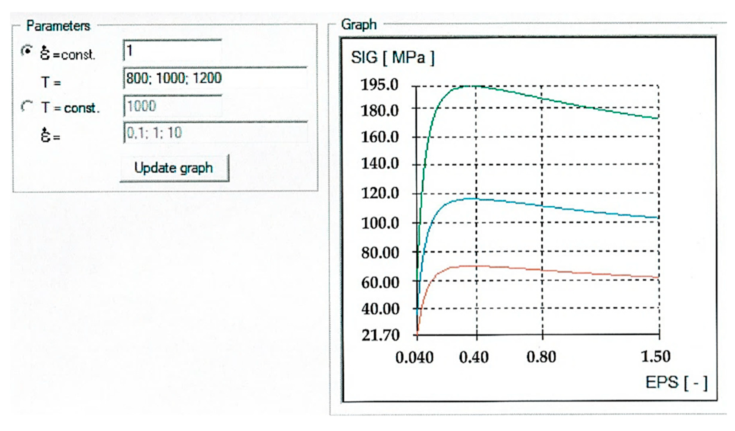
The mechanical model of the 55NiCrMoV7 steel under hot conditions was described according to Hansel–Spittel [27,28,29,30] in a simplified form (see Equation (1)), where σ is a flow stress (MPa); e is the natural constant; T is the deformation temperature (°C); ε is the true strain (-); is the strain rate (s−1); A; m1–m4 are the material constants (see Table 2). The dependence of flow stress of the 55NiCrMoV7 material model on effective plastic strain at temperatures 800 °C, 1000 °C, 1200 °C, at constant strain rate = 1 is shown in Figure 2.
The heat transfer coefficient between dies and ingot was α = 2.104 W∙m−2∙K−1, friction was defined by the “Coulomb-Tresca” law with the Tresca friction factor m = 0.3 and Coulomb friction coefficient µ = 0.15 [31,32].
The ambient temperature was 25 °C, with the heat transfer coefficient between the formed ingot and ambient air α = 10 W ∙m−2∙K−1.
The forging procedure of a polygonal ingot 8K and a slab ingot P40N is given in Table 3. Flat dies were used, for final forging 600 mm of width. Swaging dies were used for upsetting the ingot/billet.
2.2. Experimental Procedure
A trial melt of the 55NiCrMoV7 was manufactured at a steel plant and one newly designed P40N slab ingot was casted. The aim of the experiment was to verify the improvement of the internal quality of plate-type forgings.
The production of steel was conducted by oxidative melting technology using the technological residue in electric arc furnace and subsequently processed on secondary metallurgy aggregates. The chemical composition of the steel after vacuum degassing is in Table 4.
In order to prevent reoxidation of the steel by atmospheric oxygen, the casting stream was protected with argon. The casting process was standard. The ingot head was treated with exothermic and insulating powder. The solidified ingot (in 9 h) was stripped and head shrinkage cavity and surface of ingot’s body were visually checked.
Forging of an experimental P40N slab ingot was carried out on a 120 MN hydraulic press.
Forged plates were control cooled and subsequently quenched and tempered by regime 850 °C/11 h/oil + 550 °C/17 h/air + 520 °C/17 h/air.
Ultrasonic testing was performed on the machined surface of forging according to Specification and Level SEP 1921/1984-2/D/d with a DIO 1000PA defectoscope manufactured by STARMANS electronics, s.r.o., Prague, Czech Republic.
The control chemical analysis of forging samples was verified by optical emission spectrometry on a stationary SPECTROMAX analyser supplied by SPECTRO Analytical Instruments, GmbH, Kleve, Germany, ad, in the case of oxygen, carbon and sulphur determination by elemental analysis on a stationary combustion element analyser Eltra ONH 2000, or Eltra CS2000 made by the company ELTRA, GmbH, Haan, Germany. The phosphorus content was determined by GDOES “Bulk” analysis using a GDA750A spectrometer, SPECTRUMA Analytik, GmbH, Hof, Germany.
The macrostructure of the samples was studied after etching with 10 % nitric acid.
The content of non-metallic inclusions was determined according to the ASTM E45, method A. The size of the original austenitic grain was determined after heat treatment and etching with an etchant called ALKILO I (saturated solution of picric acid + hydrochloric acid + detergent) according to ASTM E 112, using the comparative method.
Structural analyses were performed after etching samples by 4% nitric acid. IX 70 and GX 51 light microscopes manufactured by the company OLYMPUS Co., Tokyo, Japan was used for microscopic observations.
3. Results
3.1. Results of Forging Simulation of P40N Slab Ingot
Figure 3 shows forging of the surfaces of a P40N slab ingot, where in the first phase a polygon is forged, i.e., the sides are shaped by reduction of approximately 300 mm to the dimensions 1550 mm width × 900 mm thickness.
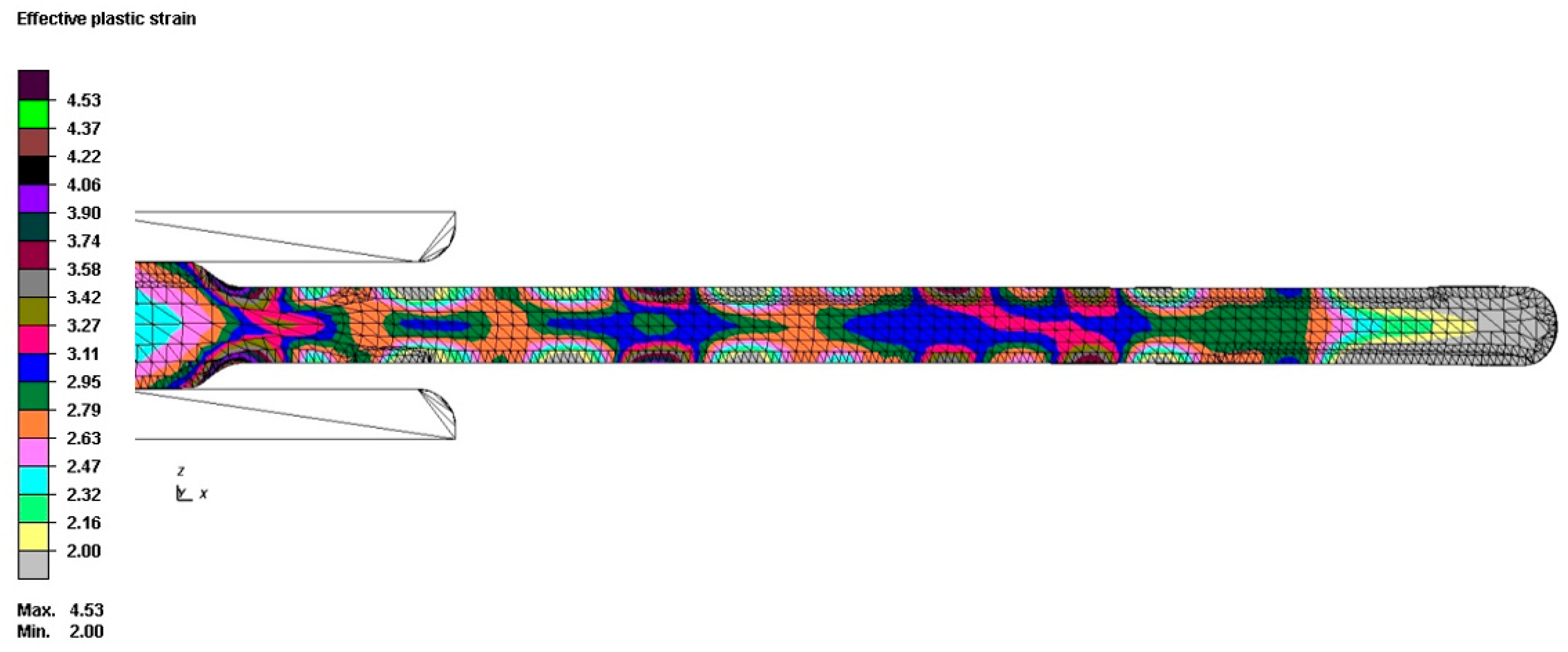
Figure 4 presents the “effective plastic strain” following forging of a P40N slab ingot by drawing into a forging of 1010 mm width × 310 mm thickness × 5350 mm length before cutting the ends. On the end of the forging which correspond with bottom of the original P40N ingot, the effective plastic strain does not exceed the values of 2 in length of approximately 350 mm. The strain is uneven over the cross section and falls from the axis towards the surface. The value of the maximum effective plastic strain is 4.53, but only on the surface and locally in a few places. On the surface there are also places where the effective plastic strain does not reach the value 2.
3.2. Results of Forging of Conventional 8K Polygonal Ingot
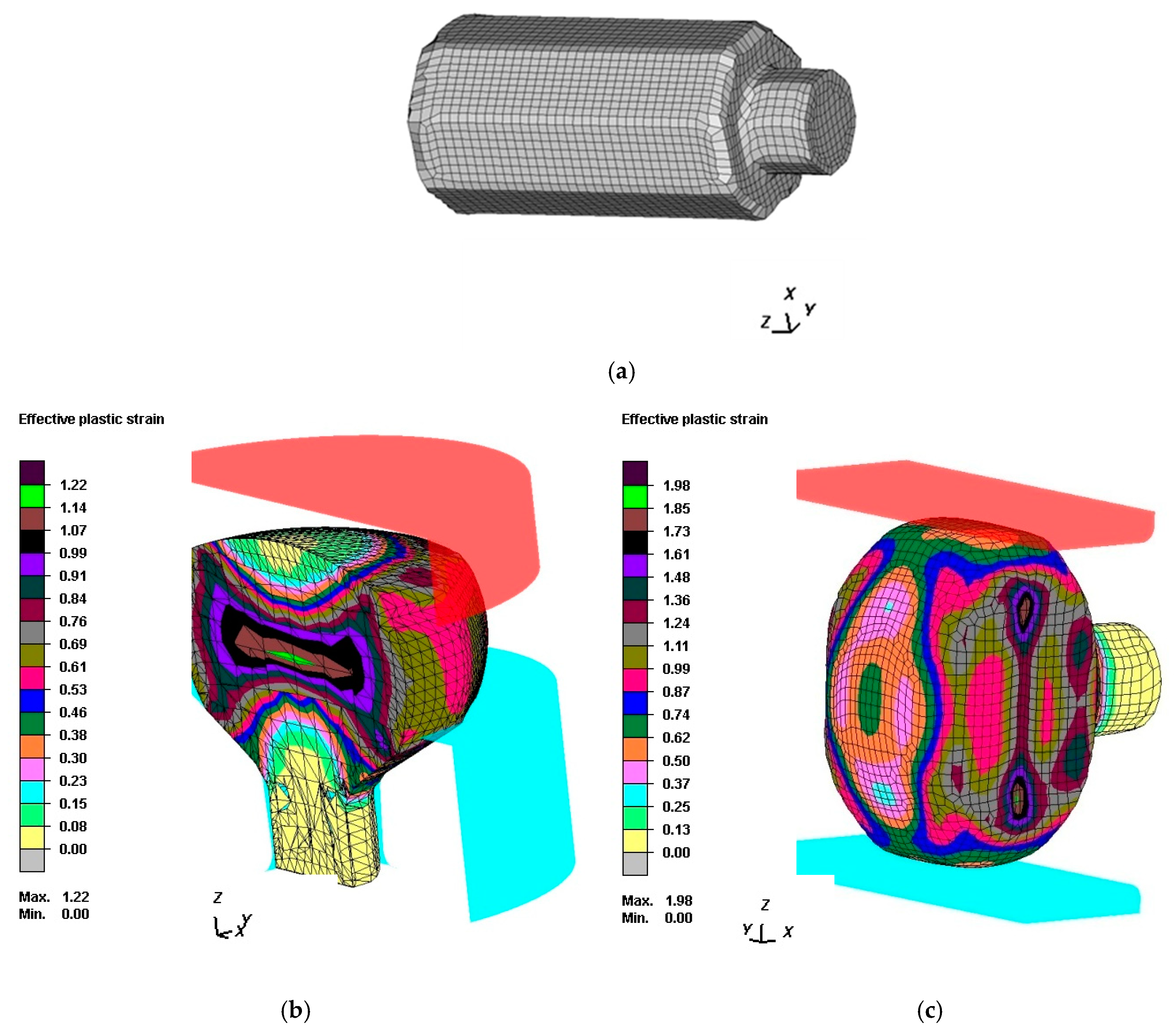
The forged tong hold and a parallel octagon body of the original 8K polygonal ingot is documented in Figure 5a. Figure 5b shows the upsetting of a conventional 8K polygonal ingot. The cross section clearly shows the uneven course of effective plastic strain typical for upsetting. The result of uneven deformation is the creation of additional tensile stresses on the side surface of the upset body, undesirable shape change of the side walls of the forging in the form of a barrel shape, difficult through-forming certain areas of the forging, and non-uniformity of the resulting structure and the mechanical properties. This was followed by forging into a billet of the type rectangle cross section forging (Figure 5c) and further upsetting (Figure 5d) Figure 5e shows the initial state after the second upsetting, where the billet is only drawn to its final required dimensions. The overall effective plastic strain is uneven, and the lowest values are in both ends of the forging. The strain is evened out by further forging into the required dimensions, and a value of 5 and more for effective plastic strain is achieved for attainment of the final dimensions over the entire volume, see Figure 5f.
The goal of numerical forging simulations was to evaluate the existing procedure for forging a plate from a conventional polygonal ingot 8K and P40N slab ingot. The calculations were time consuming because they had to simulate each reduction and each operation up until the final dimensions.
Based on the performed simulations it is evident that forging from a new P40N slab ingot has no impact on the final quality of the surface from the aspect of the polygonal shape of surfaces. Over the course of forging they will be evened out, and surfaces of the forging will be straight.
But the course of effective plastic strain is incomparable for both procedures—forging from conventional 8K and P40N slab ingot. Although in the case of a P40N slab ingot the forging reduction is 5.65, which is sufficient according to theoretical findings, effective plastic strain is highly uneven and the overall volume does not reach the designated limit value of 2. Forging consists only of drawing to the required dimensions.
For a conventional 8K polygonal ingot the effective plastic strain is more even and greater than 2 over the entire volume. But the ingot is upset twice, and the forging reduction is significantly higher, this being 11.12. This is double the value compared with a slab ingot without upsetting.
The process of forging from a conventional 8K polygonal ingot to the given dimensions gives sufficiently compliant results. Forging from a P40N slab ingot is faster and more economical, but the overall strain is highly uneven and does reach the required value of overall plastic strain, even though the forging reduction is sufficient. The absence of the upsetting before drawing is the reason for this. The purpose of upsetting is especially to increase the forging reduction, to reduce the anisotropy of mechanical properties, to achieve the radial grain.
It was confirmed that the required dimensions can be attained in several ways under different conditions. However, the results of simulation analyses indicate that it is necessary to correctly select which dimensions of forging can be forged from a P40N slab ingot and which can be forged from a conventional polygonal ingot 8K. It is important for the forging reduction to be sufficient over the entire volume of the forging, for there not to be detected unacceptable ultrasonic indications in the forging, and for the required mechanical properties to be attained.
3.3. Results—Metallographic Analysis of Plate of the 55NiCrMoV7 Steel
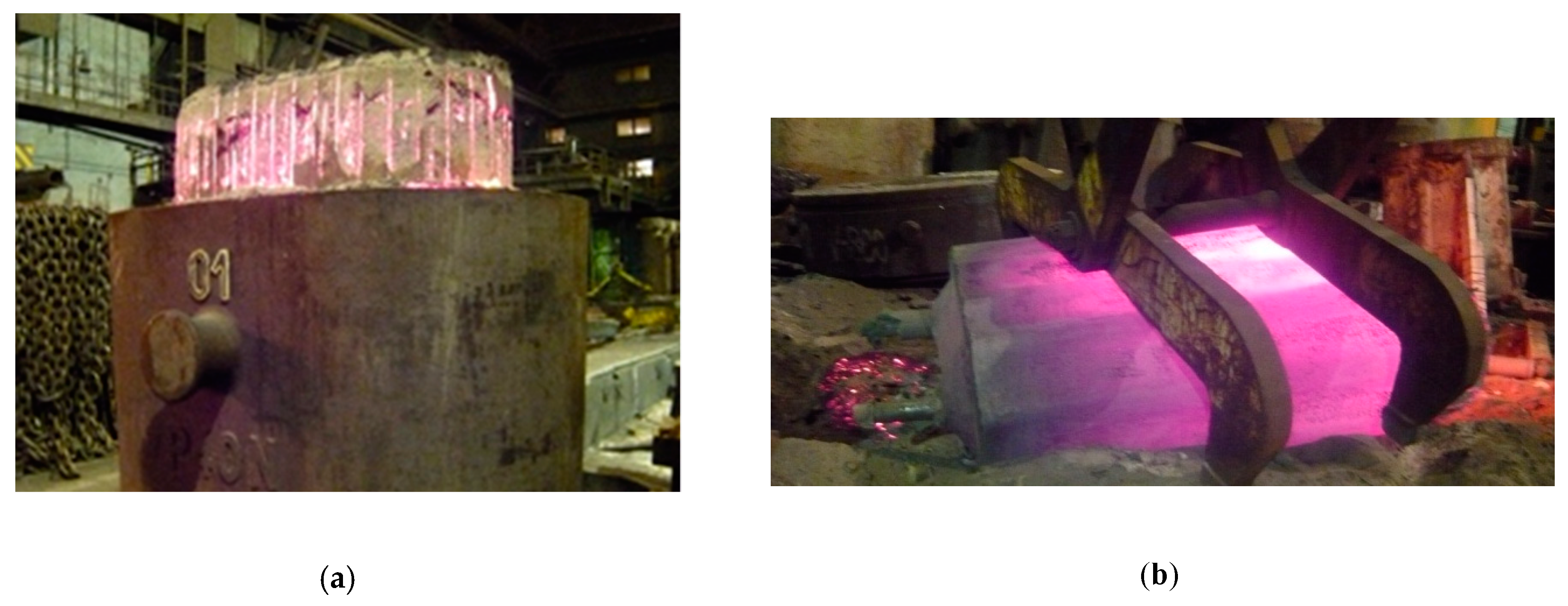
The surface quality of the P40N ingot was very good, without significant surface defects such as folds, cold shuts etc. The quality of the ingot head was also very good; the head shrinkage cavity did not even reach one third of the head height, and the shape of the shrinkage was even over the entire length of the head, without pronounced shrinkage cavity. Figure 6a. shows the head of the ingot P40N without hot top. The handling of the ingot after it was stripped is documented in Figure 6b.
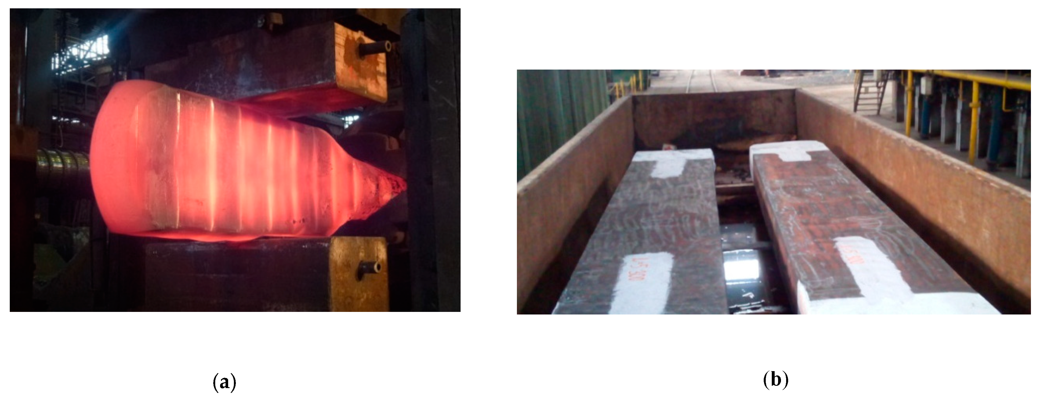
A plate having dimensions of approximately 1010 mm width × 310 mm depth × 5350 mm length was forged from a P40N ingot on a forging press in two forging operations (forging of tong hold and forging of ingot head into rectangular cross section, forging to required dimensions, see Figure 7a and cutting of ends), and this plate was then divided into two shorter plates, see Figure 7b.
Non-destructive ultrasonic examination showed compliant results for both plates, no inadmissible indications were detected. Two samples (each with dimensions of approximately 200 mm × 80 mm × 30 mm), were taken from one plate from the centre (from axis area, marked 1) and from its edge (marked 2) for carrying out a control chemical analysis, metalographic examination in cross section and measurement of hardness.
The control chemical analysis of both samples corresponded well with the chemical composition of the melt, see Table 3.
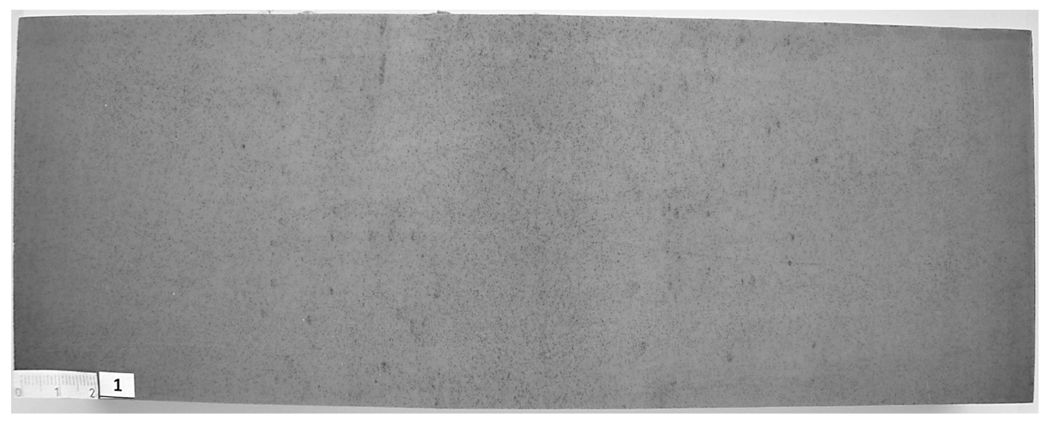
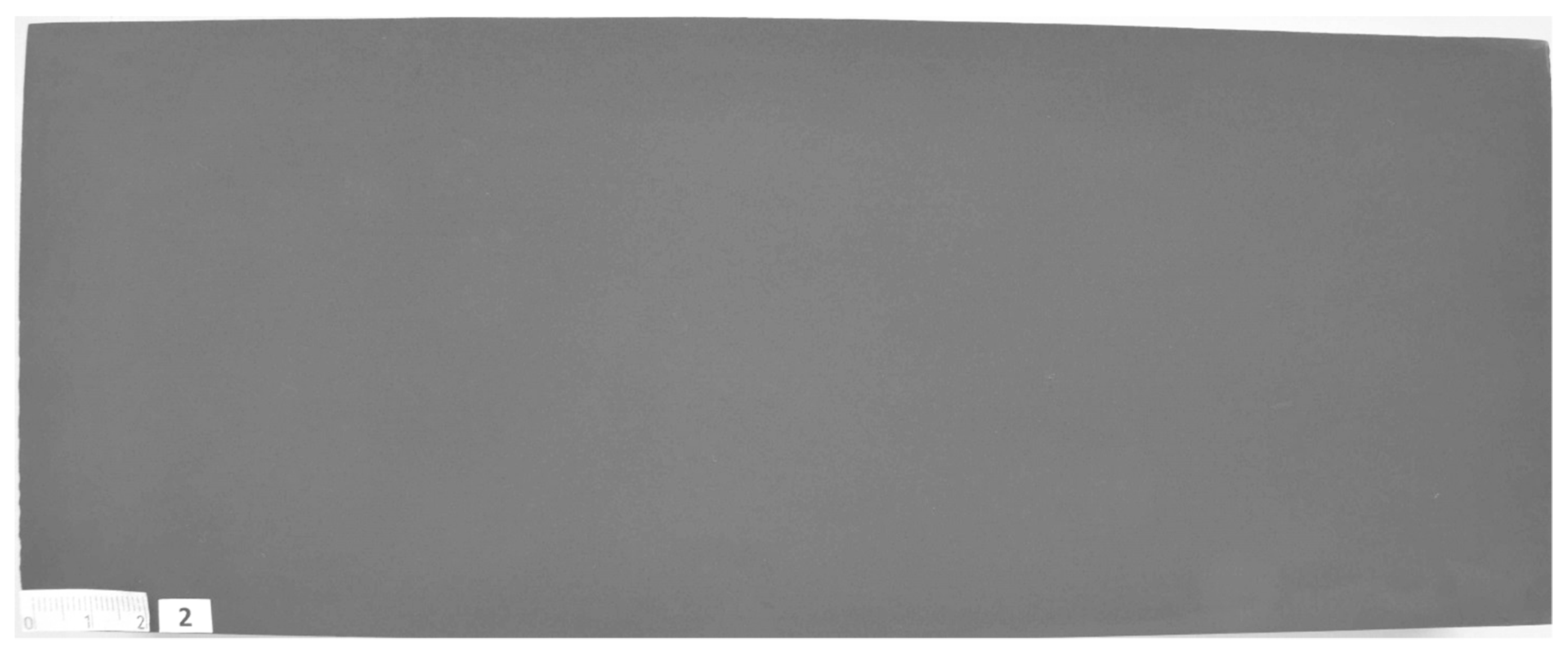
The macrostructure of both samples was fine grained, without the presence of cracks or other imperfections, see Figure 8 and Figure 9. Central segregation was more emphasised in the macrostructure of sample 1 (Figure 8).
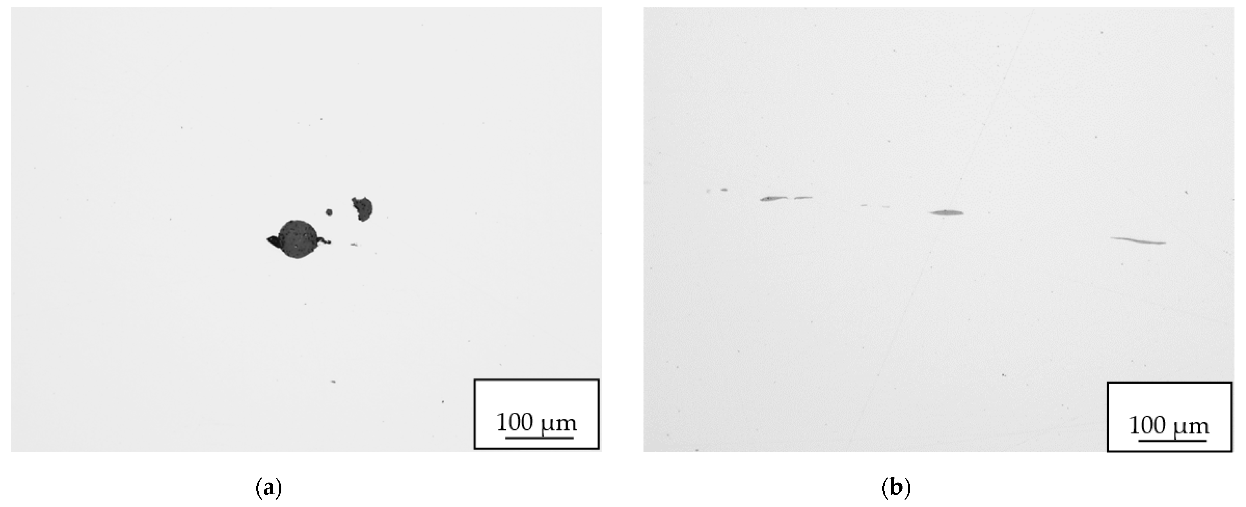
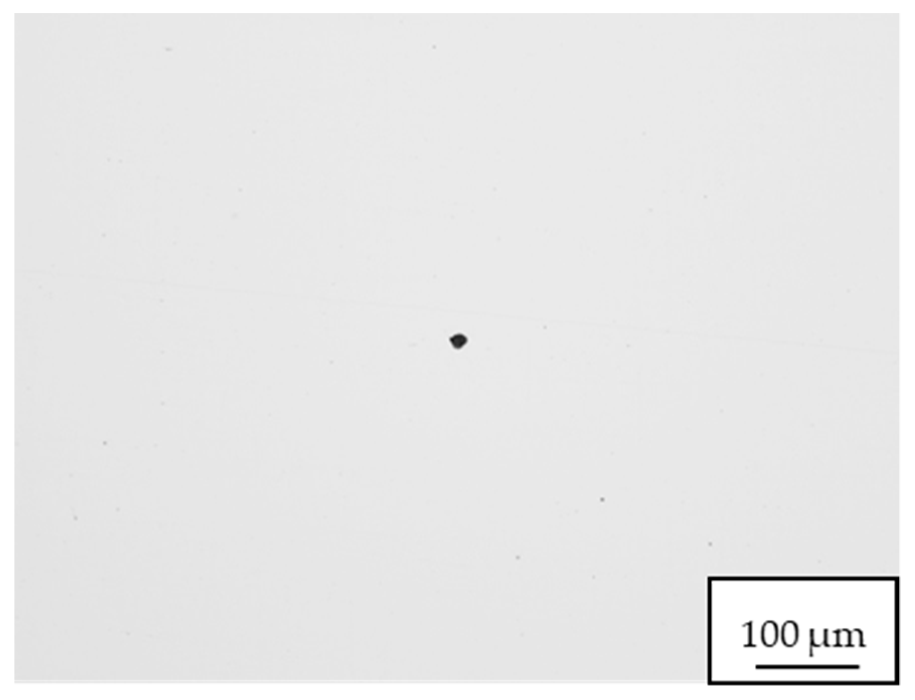
During the evaluation of micro-cleanness, the presence of a small amount of non-metallic inclusions was detected. These were most often point oxidic inclusions. In sample 1 an excessive number of type D inclusions larger than 12 µm were detected. Very occasionally we also observed elongated sulfidic non-metallic inclusions due to the forming process. Figure 10 and Figure 11 present typical examples of the inclusions found.
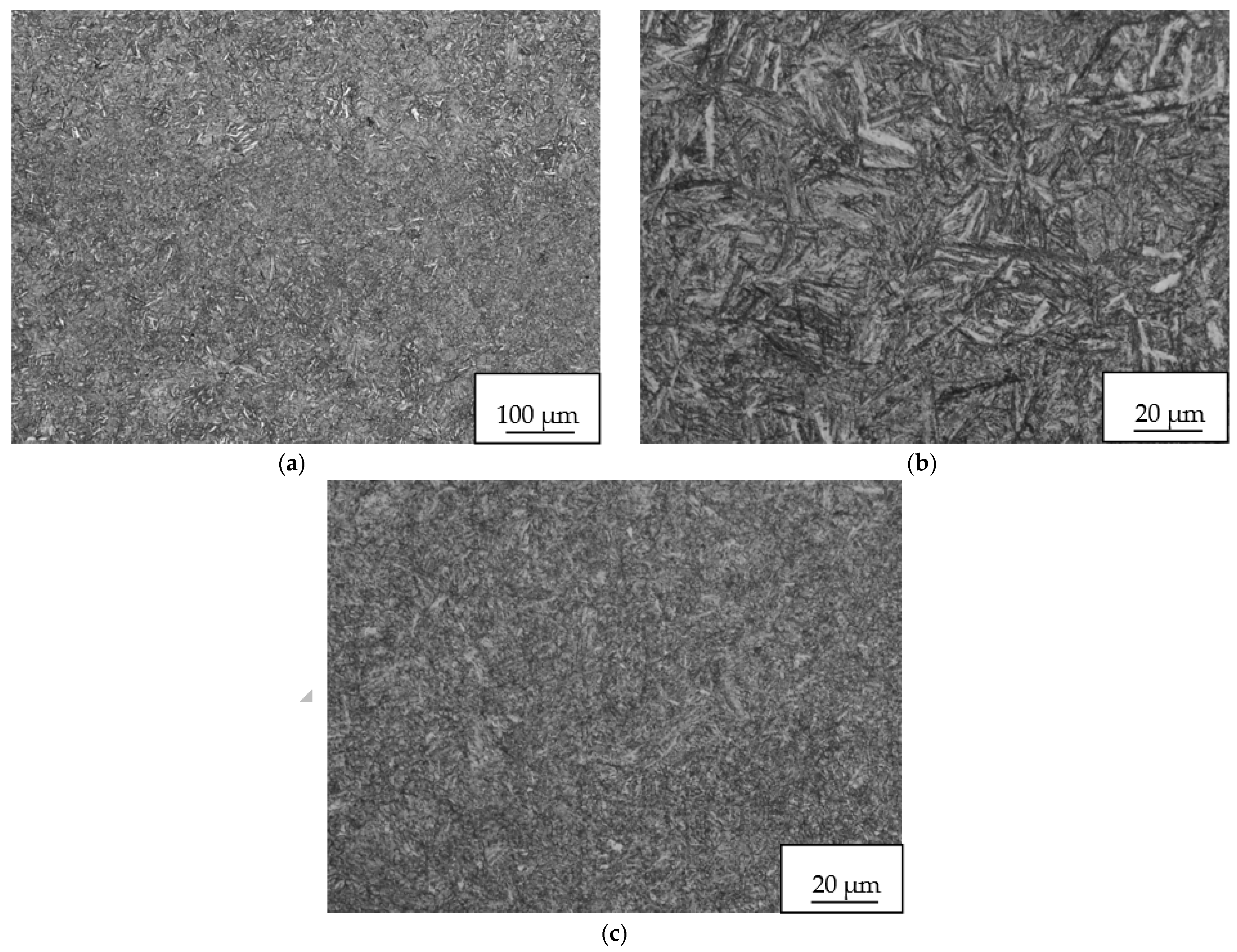
The microstructure of the steel in the centre of the plate consisted of tempered martensite with indistinct segregation bands, see Figure 12. The original grain size of austenite in segregations was G = 12 (13), and outside the segregation band G = 11 (10).
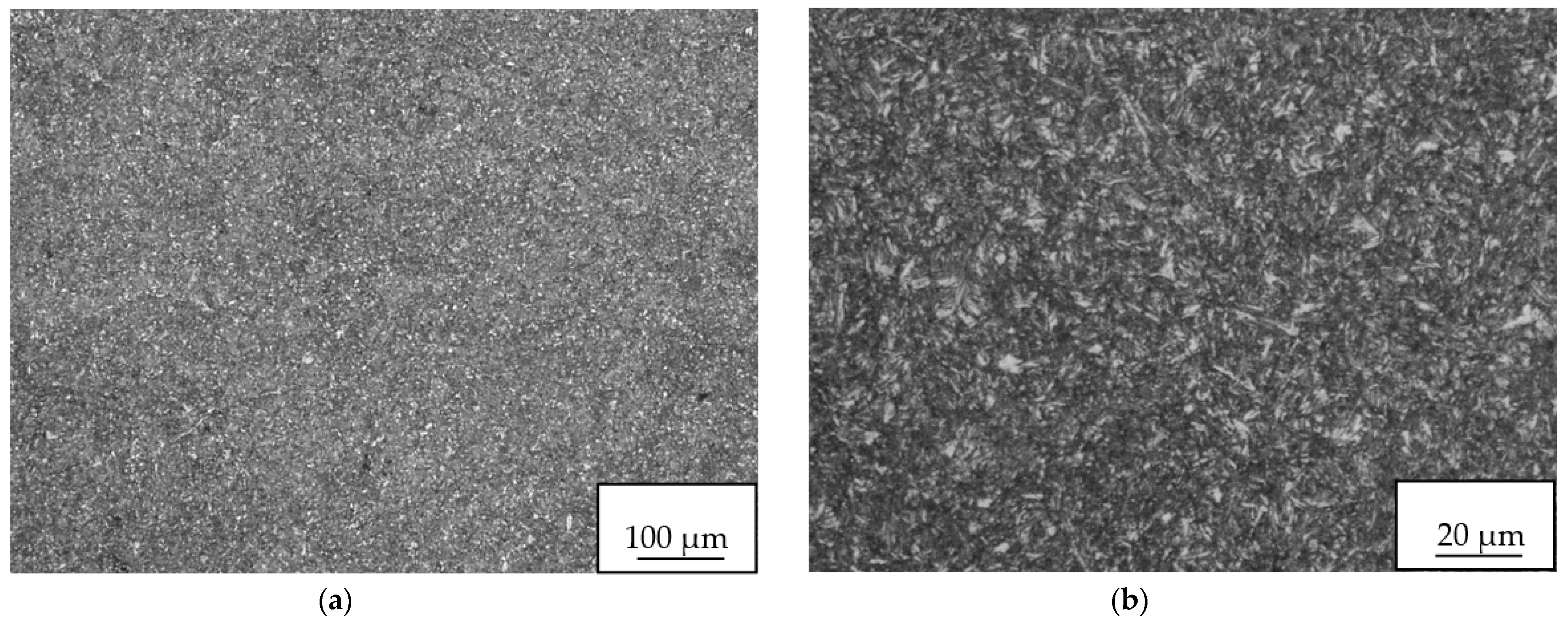
Microstructure at the edge of the plate was fine grained, tempered martensite, and is presented in Figure 13. The original grain size of austentite was very fine and corresponded to G = 12. No segregation bands were detected.
The determined Rockwell hardness values at the centre and edge of the plate were 44 ± 1.17 HRC and 44.5 ± 0.8 HRC respectively, which is in accordance to values usual for the given steel grade and structure following the aforementioned quality heat treatment. Measurement of hardness was performed 10 times on the cross section of sample 1 and also on sample 2, always evenly in the length of approximately 200 mm. Due to fine grained microstructure, significant differences in hardness values were not found.
The operational experiment showed satisfactory qualitative parameter results of the forging made from 55NiCrMoV7 tool steel. It also confirmed results obtained from the numerical simulations of casting and forging. A newly designed P40N slab ingot was successfully verified for the 55NiCrMoV7 tool steel grade.
4. Conclusions
The paper presented the results of numerical modelling and an operational experiment of forging of a newly designed P40N slab ingot, weighing about 40 t, from the 55NiCrMoV7 tool steel. By numerical simulations the effect of forging conditions on the final steel plate-forging properties with dimensions of approximately 1010 mm width × 310 mm thickness × 5350 mm length was studied. The results obtained were compared with the numerical simulation results of a conventional 8K polygonal forging ingot of similar weight. The most important numerical simulation findings can be summarized as follows:
- Forging from a P40N slab ingot has no impact on the resultant quality of the surface from the aspect of the polygonal shape of surfaces.
- The forging reduction of the P40N slab ingot was sufficient, but effective plastic strain was highly uneven and did not reach the limit value 2 over the entire volume of the forging. This fact is demonstrated by the absence of an upsetting operation in contrast to the 8K ingot which was upsetted twice.
- For a conventional 8K polygonal ingot the effective plastic strain was more even and greater than 2. The forging reduction of an 8K ingot was approximately double that of a P40N ingot.
- The forging of a plate from a P40N slab ingot is faster and more economical.
- Based on previous numerical research of casting of the 55NiCrMoV7 steel, it was found that the range of macrosegregation in the P40N slab ingot was lower than in the 8K polygonal ingot.
- In the central axis of the ingot body of the slab ingot, a large volume of microporosity was predicted in comparison with the polygonal ingot 8K. This microporosity can be eliminated by forging.
The results obtained in the operational experiment showed satisfactory qualitative parameters of the forging made from 55NiCrMoV7 tool steel which were in accordance with the predicted results of numerical simulations. The overall results indicated that in selected cases the use of a P40N slab ingot instead of the conventional 8K polygonal forging ingot can be considered in the production of certain plate-type forgings.
The solution to the problem presented in this paper has not yet been openly published by any other authors. Therefore, the results obtained are novel and can be useful for other researchers.
Within future research, other tool steel slab ingots should be cast and their properties evaluated in order to verify of the correct solution from the viewpoint of the newly designed P40N slab mould. Verification of a new mould design is also expected for other requested tool steels such as X37CrMoV5-1 and 40CrMnNiMo8-6-4.
Author Contributions
Conceptualization, methodology, writing—original draft preparation, P.J.; investigation, writing—review and editing, V.K.; methodology, formal analysis M.V.; supervision, funding acquisition, L.K. All authors have read and agreed to the published version of the manuscript.
Funding
This work was supported by the EU Regional Development Fund within the Operational Programme Research, Development and Education under the aegis of Ministry of Education, Youth and Sports of the Czech Republic; Project number CZ.02.1.01/0.0/0.0/17_049/0008399.
Institutional Review Board Statement
Not applicable
Informed Consent Statement
Not applicable
Data Availability Statement
Not applicable
Conflicts of Interest
The authors declare no conflict of interest.
References
- Kermanpur, A.; Eskandari, M.; Purmohamad, H.; Soltani, M.A.; Shateri, B. Influence of Mould Design on the Solidification of Heavy Forging Ingots of Low Alloy Steels by Numerical Simulations. Mater. Des. 2010, 31, 1096–1104. [Google Scholar] [CrossRef]
- Tashiro, K.; Watanabe, S.; Kitagawa, I.; Tamura, I. Influence of Mould Design on the Solidification and Soundness of Heavy Forging Ingots. Trans. Iron Steel Inst. Jpn. 1983, 23, 312–321. [Google Scholar] [CrossRef] [Green Version]
- Baoguang, S.; Xiuhong, K.; Dianzhong, L. A Novel Technique for Reducing Macrosegregation in Heavy Steel Ingots. J. Mater. Process. Technol. 2010, 210, 703–711. [Google Scholar] [CrossRef]
- Kearney, M.; Crabbe, M.; Talamantes-Silva, J. Development and Manufacture of Large Plate Mill Rolls. Ironmak. Steelmak. 2013, 34, 380–383. [Google Scholar] [CrossRef]
- Ghosh, A. Segregation in Cast Products. Sadhana 2001, 26, 5–24. [Google Scholar] [CrossRef]
- Radovic, Z.; Lalovic, M. Numerical Simulation of Steel Ingot Solidification Process. J. Mater. Process. Technol. 2005, 160, 156–159. [Google Scholar] [CrossRef]
- Skobir, D.A.; Godec, M.; Balcar, M.; Jenko, M. The Determination of Steel Cleanliness in the As-Cast Ingot 26NiCrMoV145. Vacuum 2010, 84, 205–208. [Google Scholar] [CrossRef]
- Thuinet, L.; Combeau, H. Prediction of Macrosegregation during the Solidification Involving a Peritectic Transformation for Multicomponent Steels. J. Mater. Sci. 2004, 39, 7213–7219. [Google Scholar] [CrossRef]
- Sinczak, J.; Majta, J.; Glowacki, M.; Pietryk, M. Prediction of Mechanical Properties of Heavy Forgings. J. Mater. Process. Technol. 1998, 80–81, 166–173. [Google Scholar] [CrossRef]
- Obiko, J.; Mwema, F.M. Stress and Strain Distribution in the upsetting process. In Handbook of Research on Advancements in Manufacturing, Materials, and Mechanical Engineering; IGI Global: Hershey, PA, USA, 2020; pp. 288–301. [Google Scholar]
- Lan, P.; Zhang, J.Q. Numerical Analysis of Macrosegregation and Shrinkage Porosity in Large Steel Ingot. Ironmak. Steelmak. 2014, 41, 598–606. [Google Scholar] [CrossRef]
- Ludwig, A.; Wu, M.; Kharicha, A. On Macrosegregation. Metall. Mater. Trans. A 2015, 46, 4854–4867. [Google Scholar] [CrossRef]
- Li, W.; Shen, H.; Zhang, X.; Liu, B. Modelling of Species Transport and Macrosegregation in Heavy Steel Ingots. Metall. Mater. Trans. B 2014, 45, 464–471. [Google Scholar] [CrossRef]
- Song, W.; Zhang, J.M.; Liu, Y.; Wang, S.X.; Wang, B. Numerical Simulation of Solidification Structure of 6.5-wt. % Si Steel Ingot Slab. Ironmak. Steelmak. 2015, 42, 656–663. [Google Scholar] [CrossRef]
- Marx, K.; Rödl, S.; Schramhauser, S.; Seemann, M. Optimization of the Filling and Solidification of Large Ingots. La Metallurgica Italiana 2014, 11–12, 11–19. [Google Scholar]
- Tkadlečková, M.; Michalek, K.; Machovčák, P. Prediction and Casting of Solidification of Slab Steel Ingot. In Proceedings of the Metal 2015: 24th International Conference on Metallurgy and Material, Brno, Czech Republic, 3–5 June 2015; 2015; pp. 54–59. [Google Scholar]
- Tkadlečková, M.; Michalek, K.; Machovčák, P.; Kováč, M.; Socha, L. Study Of Casting and Solidification of Slab Ingot from Tool Steel using Numerical Modelling. Arch. Metall. Mater. 2015, 60, 2873–2878. [Google Scholar] [CrossRef] [Green Version]
- Tkadlečková, M.; Michalek, K.; Gryc, K.; Socha, L.; Machovčák, P. Prediction of Qualitative Parameters of Slab Steel Ingot Using Numerical Modelling. Metal. Metall. 2016, 55, 395–398. [Google Scholar]
- Tkadlečková, M.; Michalek, K.; Gryc, K.; Socha, L.; Jonšta, P.; Saternus, M.; Pieprzyca, J.; Merder, T. Research and Development on the Solidification of Slab Ingots from Special Tool Steels. Arch. Metall. Mater. 2017, 62, 1453–1458. [Google Scholar] [CrossRef] [Green Version]
- Tkadlečková, M.; Jonšta, P.; Carbol, Z.; Sušovský, M.; Michalek, K.; Socha, L.; Sviželová, J.; Zwyrtek, J. Distribution of Porosity and Macrosegregation in Slab Steel Ingot. In IOP Conference Series: Materials Science and Engineering; IOP Publishing: Bristol, UK, 2017; Volume 179, p. 012067. [Google Scholar] [CrossRef] [Green Version]
- Wolfgarten, M.; Rosenstock, D.; Schaeffer, L.; Hirt, G. Implementation of an open-die forging process for large hollow shafts for wind power plants with respect to an optimized microstructure. AIM 2015, 107, 43–49. [Google Scholar]
- Choi, S.K.; Chun, M.S.; Van Tyne, C.J.; Moon, Y.H. Optimization of open die forging of round shapes using FEM analysis. J. Mater. Process. Technol. 2006, 172, 88–95. [Google Scholar] [CrossRef]
- Hideki, K.; Takefumi, A.; Yoichi, T.; Tatsua, T.; Yutaka, I. Development of Forging Process Design to Close Internal Voids. J. Mater. Process. Technol. 2010, 210, 415–422. [Google Scholar] [CrossRef]
- Scarabello, D.; Ghiotti, A.; Bruschi, S. FE Modelling of Large Ingot Hot Forging. Int. J. Mater. Form. 2010, 3, 335–338. [Google Scholar] [CrossRef]
- Zhang, X.-X.; Cui, Z.-S.; Chen, W.; Li, Y. A Criterion for Void Closure in Large Ingots during Hot Forging. J. Mater. Process. Technol. 2009, 209, 1950–1959. [Google Scholar] [CrossRef]
- Banaszek, G.; Stefanik, A. Theoretical and Laboratory Modelling of the Closure of Metallurgical Defects during Forming of a Forging. J. Mater. Process. Technol. 2006, 177, 238–242. [Google Scholar] [CrossRef]
- Hansel, A.; Spittel, T. Kraft-und Arbeitsbedarf bildsamer Formgeburgsverfahren, 1st ed.; Deutscher Verlag fur Grundstoffindustrie: Leipzig, Germany, 1978; 528p. [Google Scholar]
- Chen, X.; Wang, N.; Ma, X.; Zhou, H. Hot Deformation Behaviour and Hansel-Spittel constitutive Model of Cr5 Alloy for Heavy Backup Roll. Int. J. Comput. Mater. Sci. Surf. Eng. 2018, 7, 205–217. [Google Scholar] [CrossRef]
- Liang, Q.; Liu, X.; Li, P.; Zhang, X. Development and Application of High-Temperature Constitutive Model of HNi55-7-4-2 Alloy. Metals 2020, 10, 1250. [Google Scholar] [CrossRef]
- Chadha, K.; Shahriari, D.; Jahazi, M. An Approach to Develop Hansel-Spittel Constitutive Equation during Ingot Breakdown Operation of Low Alloy Steels. In Frontiers in Materials Processing, Applications, Research and Technology; Muruganant, M., Chirazi, A.R.B., Eds.; Springer: Singapore, 2017. [Google Scholar] [CrossRef]
- Joun, M.S.; Moon, H.G.; Choi, I.S.; Lee, M.C.; Jun, B.Y. Effects of Friction Laws on Metal Forming Processes. Tribol. Int. 2009, 42, 311–319. [Google Scholar] [CrossRef]
- Zhang, D.W.; Ou, H. Relationship between Friction Parameters in a Coulomb-Tresca Friction Model for Bulk Metal Forming. Tribol. Int. 2016, 95, 13–18. [Google Scholar] [CrossRef]
Figure 1.
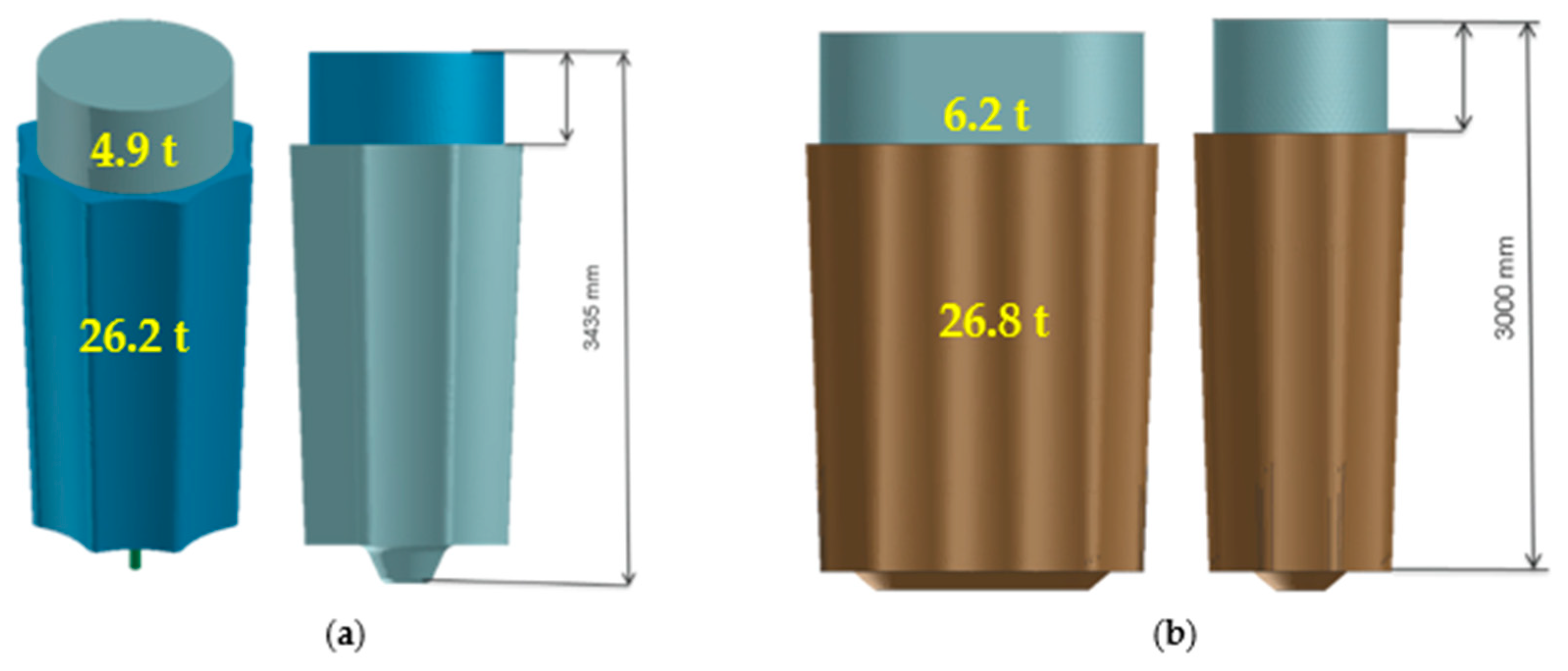
Experimental ingots. (a) Conventional polygonal ingot 8K with 4.9 t weighing of the hot top and 26.2 t weighing of the ingot body; (b) Newly designed Slab ingot P40N with 6.2 t weighing of the hot top and 26.8 t weighing of the ingot body.
Figure 1.
Experimental ingots. (a) Conventional polygonal ingot 8K with 4.9 t weighing of the hot top and 26.2 t weighing of the ingot body; (b) Newly designed Slab ingot P40N with 6.2 t weighing of the hot top and 26.8 t weighing of the ingot body.

Figure 2.
The dependence of flow stress (SIG) of the 55NiCrMoV7 material model on effective plastic strain (EPS) at temperatures 800 °C (green curve), 1000 °C (blue curve), 1200 °C (red curve), at constant strain rate = 1.
Figure 2.
The dependence of flow stress (SIG) of the 55NiCrMoV7 material model on effective plastic strain (EPS) at temperatures 800 °C (green curve), 1000 °C (blue curve), 1200 °C (red curve), at constant strain rate = 1.

Figure 3.
Forging process of a polygonal shape of surfaces of the P40N slab ingot to flat surfaces of billet. (a) Initial shape of the P40N ingot; (b) Flat surfaces billet; (c) The billet of 1550 mm width × 900 mm thickness.
Figure 3.
Forging process of a polygonal shape of surfaces of the P40N slab ingot to flat surfaces of billet. (a) Initial shape of the P40N ingot; (b) Flat surfaces billet; (c) The billet of 1550 mm width × 900 mm thickness.


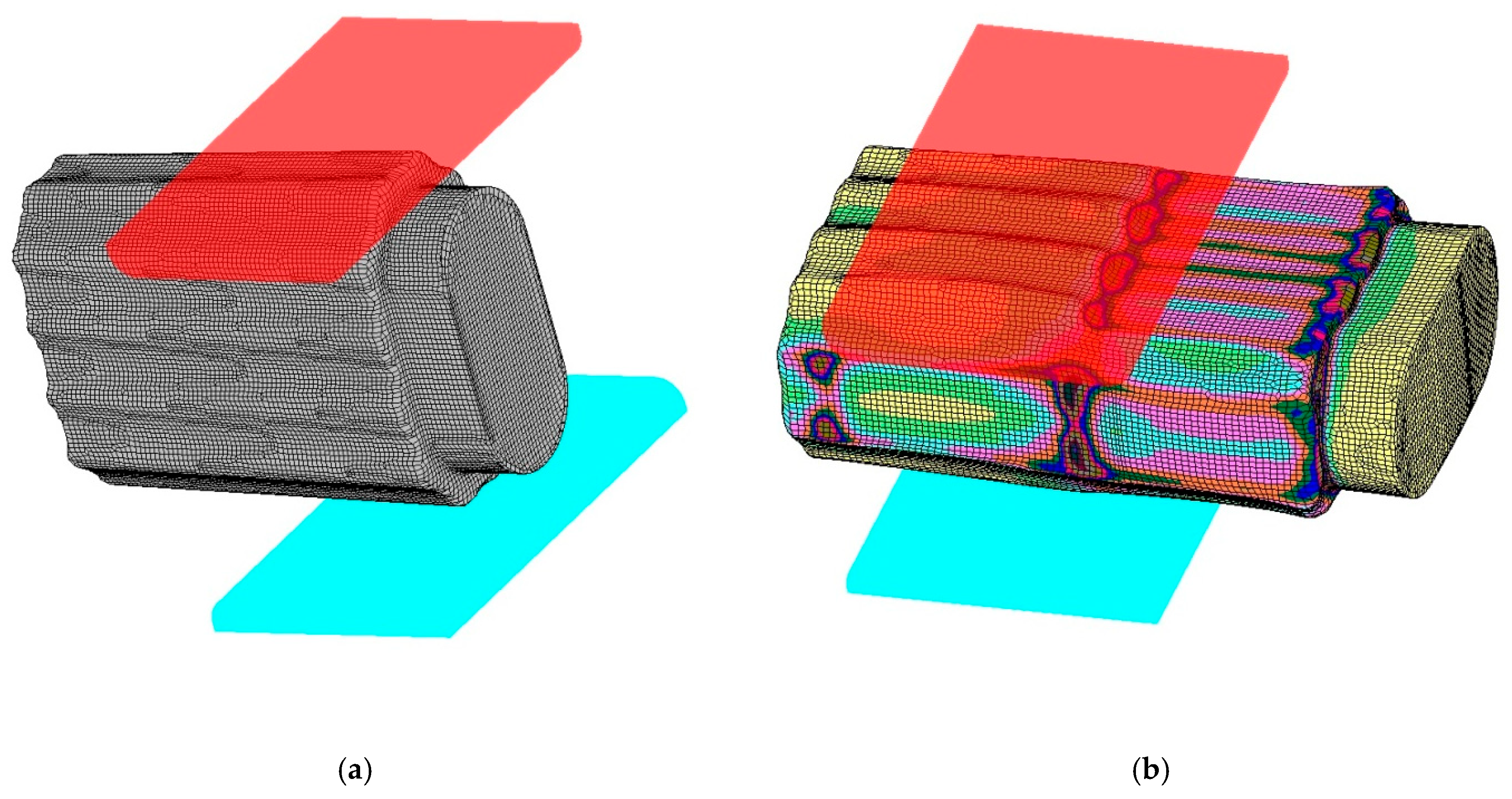
Figure 4.
Effective plastic strain distribution calculated by numerical simulation of forging the plate with 310 mm of thickness from the P40N slab ingot.
Figure 4.
Effective plastic strain distribution calculated by numerical simulation of forging the plate with 310 mm of thickness from the P40N slab ingot.

Figure 5.
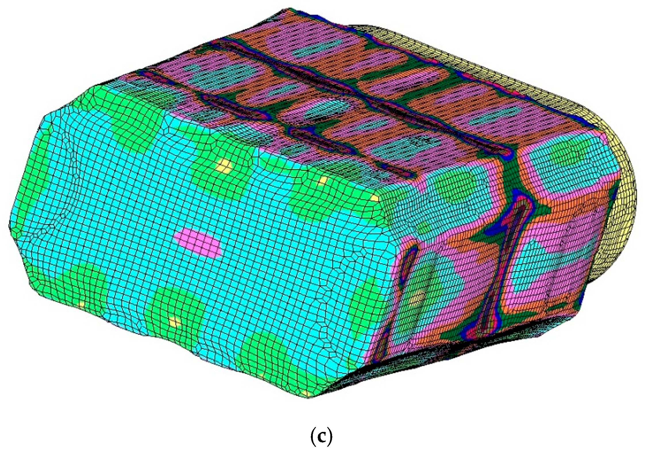
Procedure of numerical simulation of forging process of plate from a conventional 8K polygonal forging ingot. (a) A parallel octagon body of the 8K ingot with equivalent diameter of 1200 mm. (b) Cross section view of upsetting of the ingot 8K between flat swaging dies. (c) Forging to rectangle cross section billet between flat dies. (d) Upsetting of rectangle cross section billet between flat swaging dies. (e) The shape of the billet after the second upsetting between flat swaging dies. (f) Scheme 310 mm of thickness from an initial conventional 8K polygonal ingot.
Figure 5.
Procedure of numerical simulation of forging process of plate from a conventional 8K polygonal forging ingot. (a) A parallel octagon body of the 8K ingot with equivalent diameter of 1200 mm. (b) Cross section view of upsetting of the ingot 8K between flat swaging dies. (c) Forging to rectangle cross section billet between flat dies. (d) Upsetting of rectangle cross section billet between flat swaging dies. (e) The shape of the billet after the second upsetting between flat swaging dies. (f) Scheme 310 mm of thickness from an initial conventional 8K polygonal ingot.


Figure 6.
(a) Head of stripped slab ingot P40N; (b) Slab ingot P40N handling.

Figure 7.
(a) Drawing operation in the forging of the plate from the P40N slab ingot; (b) forged plates from P40N slab ingot.
Figure 7.
(a) Drawing operation in the forging of the plate from the P40N slab ingot; (b) forged plates from P40N slab ingot.

Figure 8.
Central segregation in macrostructure of sample 1.

Figure 9.
Macrostructure at edge of plate (sample 2).

Figure 10.
Non-metallic inclusions in the centre of steel plate (sample 1). (a) Excessive D-type oxidic inclusions in metal matrix; (b) Sulfidic inclusions founded in metal matrix.
Figure 10.
Non-metallic inclusions in the centre of steel plate (sample 1). (a) Excessive D-type oxidic inclusions in metal matrix; (b) Sulfidic inclusions founded in metal matrix.

Figure 11.
Oxidic inclusions at the edge of steel plate (sample 2).

Figure 12.
Microstructure in centre of steel plate consisted of tempered martensite (sample 1). (a) Tempered martensitic microstructure of the steel outside segregation; (b) Detail of the tempered martensitic microstructure of the steel outside segregation; (c) Detail of tempered martensite in segregation band.

Figure 13.
Fine grained, tempered martensite microstructure at edge of steel plate (sample 2). (a) Microstructure of steel formed by tempered martensite; (b) Detail of the tempered martensitic microstructure of steel.
Figure 13.
Fine grained, tempered martensite microstructure at edge of steel plate (sample 2). (a) Microstructure of steel formed by tempered martensite; (b) Detail of the tempered martensitic microstructure of steel.


Table 1.
Thermo-dynamic properties of the 55NiCrMoV7 steel depending on temperature.
| Temperature T (°C) | Specific Heat Capacity c (kJ.kg−1.K−1) | Density ρ (kg.m−3) | Thermal Conductivity λ (W.m−1.K−1) |
|---|---|---|---|
| 900 | 628.8 | 7492 | 24.8 |
| 1000 | 639.4 | 7434 | 26.0 |
| 1100 | 650.2 | 7385 | 27.3 |
Table 2.
Material constants of the 55NiCrMoV7 steel in the Hansel–Spittel model (parameter values were obtained from the approximation of Equation (1).
Table 2.
Material constants of the 55NiCrMoV7 steel in the Hansel–Spittel model (parameter values were obtained from the approximation of Equation (1).
| A | m1 | m2 | m3 | m4 |
|---|---|---|---|---|
| 1524.9805 | −0.00257 | −0.19406 | 0.14462 | −0.07172 |
Table 3.
The forging procedure of an 8K polygonal ingot and a P40N slab ingot.
| Polygonal 8K Ingot | Slab Ingot P40N |
|---|---|
| The first operation | |
| Heating to upper forging temperature of 1100 °C | Heating to upper forging temperature of 1100 °C |
| Forging of tong hold, flatten the bottom of ingot | Forging of tong hold, flatten the bottom of ingot |
| Forging on an octagon, equivalent diameter of 1200 mm | Forging to 1300 mm of width × 600 mm of thickness × 4460 mm of length (eq. diameter of 998 mm) |
| The second operation | |
| Heating to 1100 °C | Heating to 1100 °C |
| Upsetting to a diameter of 2200 mm | Target on maximum sharpness of the edges |
| Forging in the first axis of cross section of an upsetted ingot to a diameter of 1250 mm | Forging to final dimensions 1010 mm of width × 310 mm of thickness × length with a use of flat dies of 600 mm width. Cut only from “head-end” of the billet. |
| Forging to a diameter of 1600 mm × 1050 mm (eq. diameter of 1465 mm) | |
| The third operation | |
| Heating to 1100 °C | |
| Upsetting to a height of 1400 mm | |
| Straighten the “bottom-end” of the billet | |
| Forging to 1300 mm of width × 600 mm of thickness (eq. diameter of 998 mm) | |
| The fourth operation | |
| Heating to 1100 °C | |
| Forging to final dimensions 1010 mm of width × 310 mm of thickness × length with a use of flat dies of 600 mm width. Cut only from “head-end” of the billet. | |
Table 4.
Chemical composition of experimentally produced 55NiCrMoV7 tool steel/wt.%.
| C | Mn | Si | P | S | Cu | Ni | Cr | Mo | Al | V |
|---|---|---|---|---|---|---|---|---|---|---|
| 0.57 | 0.69 | 0.22 | 0.010 | 0.001 | 0.11 | 1.60 | 1.05 | 0.450 | 0.013 | 0.071 |
Publisher’s Note: MDPI stays neutral with regard to jurisdictional claims in published maps and institutional affiliations. |
© 2021 by the authors. Licensee MDPI, Basel, Switzerland. This article is an open access article distributed under the terms and conditions of the Creative Commons Attribution (CC BY) license (http://creativecommons.org/licenses/by/4.0/).
Share and Cite
MDPI and ACS Style
Jonšta, P.; Kurka, V.; Vindyš, M.; Kander, L. The Effect of Forging Conditions on Final Macrostructure of Slab Ingot from the 55NiCrMoV7 Tool Steel. Metals 2021, 11, 435. https://0-doi-org.brum.beds.ac.uk/10.3390/met11030435
AMA Style
Jonšta P, Kurka V, Vindyš M, Kander L. The Effect of Forging Conditions on Final Macrostructure of Slab Ingot from the 55NiCrMoV7 Tool Steel. Metals. 2021; 11(3):435. https://0-doi-org.brum.beds.ac.uk/10.3390/met11030435
Chicago/Turabian StyleJonšta, Petr, Vladislav Kurka, Marek Vindyš, and Ladislav Kander. 2021. "The Effect of Forging Conditions on Final Macrostructure of Slab Ingot from the 55NiCrMoV7 Tool Steel" Metals 11, no. 3: 435. https://0-doi-org.brum.beds.ac.uk/10.3390/met11030435
Note that from the first issue of 2016, this journal uses article numbers instead of page numbers. See further details here.