
Twinning of Tetrahedrite—OD Approach


Department of Geoscience and Natural Resources Management, University of Copenhagen, Østervoldgade 10, 1350 København, Denmark
Minerals 2021, 11(2), 170; https://0-doi-org.brum.beds.ac.uk/10.3390/min11020170
Submission received: 19 January 2021
/
Revised: 3 February 2021
/
Accepted: 3 February 2021
/
Published: 7 February 2021
(This article belongs to the Special Issue Modularity and Twinning in Mineral Crystal Structures)
Abstract
:The common twinning of tetrahedrite and tennantite can be described as an order–disorder (OD) phenomenon. The unit OD layer is a one-tetrahedron-thick (111) layer composed of six-member rings of tetrahedra, with gaps between them filled with Sb(As) coordination pyramids and triangular-coordinated (Cu, Ag). The stacking sequence of six-member rings is ABCABC, which can also be expressed as a sequence of three consecutive tetrahedron configurations, named α, β, and γ. When the orientation of component tetrahedra is uniform, the α, β, γ, α sequence builds the familiar cage structure of tetrahedrite. However, when the tetrahedra of the β layer are rotated by 180° against those in the underlying α configurations and/or when a rotated α configuration follows after the β configuration (instead of γ), twinning is generated. If repeated, this could generate the ABAB sequence which would modify the structure considerably. If the rest of the structure grows as a regular cubic tetrahedrite structure, the single occurrence of the described defect sequences creates a twin.
1. Introduction
Tetrahedrite is an old, long-known mineral species. It was known already to old miners as fahlerz, weissgiltigerz, grey ore, or panabase, under names mostly related to its macroscopic appearance in hand specimens. Its present name “tetrahedrite” was given by Haidinger [1] because of the common tetrahedral form shown by its crystals. The name “tennantite” was given to its As-based analogue, first described by W. and R. Phillips [2,3] from Cornwall. Early reports of the occurrence of Fe and Zn in tetrahedrite were the starting point of the long research path which, among other results, led to the chemical formula Cu12(Fe,Zn)2(Sb,As)4S13 for the most common tetrahedrite—tennantite solid solution. The voluminous literature concerned with the chemistry of natural and synthetic tetrahedrite and tennantite and with selected synonyms (e.g., binnite and coppite) has recently been summarized and referenced by Biagioni et al. [4]. The principal complication of the chemistry of this solid solution, the interplay of Fe3+and Fe2+ in tetrahedrite and tennatite, has been studied by several authors (e.g., Makovicky et al. [5,6]; Andreasen et al. [7]; Nasonova et al. [8]). It does not alter the crystal structure principles of these minerals.
The crystal structure of tetrahedrite (Figure 1) was refined by Wuensch [9] using a sample from Horhausen, Westerwald (Germany). That of tennantite was refined by Wuensch et al. [10] starting with older data of Pauling and Neuman [11], and for the tennantite-(Cu) by [12]. Structures of silver varieties were refined by, e.g., Peterson and Miller [13], Johnson and Burnham [14], Rozhdestvenskaya et al. [15], and Welch et al. [16]. Karanović et al. [17] reported the crystal structure of mercurian tetrahedrite from Serbia, confirming the results of Kalbskopf [18]. Other crystal structure investigations on mercurian tetrahedrite were reported by Kaplunnik et al. [19], Foit and Hughes [20], as well as Biagioni et al. [21], and on hakite by Škácha et al. [22]. The crystal structure of synthetic Mn-tetrahedrite was described by Chetty et al. [23], whereas Barbier et al. [24] determined the crystal structure of a Ni-containing synthetic tetrahedrite. This count can be continued by recent studies of tetrahedrite by materials scientists. What is remarkable for the tetrahedrite–tennantite structure type, is the stability of structure motif (Figure 1) under all these element substitutions.
2. Twinning of Tetrahedrite
The well-known twinning of tetrahedrite–tennantite (Figure 2) has been repeatedly described by (a selection of) those twin elements which constitute the difference between the holohedral cubic point-group symmetry 4/m −3 2/m and the point group symmetry of tetrahedrite, which is −43m, as demonstrated by its morphology (Figure 2). In the present study, we attempt to describe the structural aspect of this twinning by means of defects which can occur during the growth of tetrahedrite crystals. We concentrate on the growth scheme of this structure, selecting the layer-by-layer mechanism, the most probable growth layers being one-tetrahedron-thick (111) in the cubic structure, which also are the principal crystal form of these minerals. Although the tetrahedrite structure often is “derived” from the sphalerite structure, presence of large cavities separated from one another by single-polyhedron-thick walls leads to a much more complicated configuration of (111) growth layers than found in sphalerite (Figure 3). Variation in stacking of these layers ought to be the reason for twinning. In the present model, we present a potentially free stacking variation of layers but within well-defined layer-match rules, i.e., we presume that they behave as order-disorder (OD) layers as defined by Dornberger-Schiff [25], Ďurovič [26], and Ferraris et al. [27], among others.
There is a limited number of types of such layers in any OD structure (only one layer type in our case), with own layer-group symmetry and 2D architecture. Their relationships in any layer pair (of two identical layers) is in the OD structure always described by the same set of symmetry operations. However, this does not guarantee fixed relationships, and periodicity, for triple layers and higher n-tuples, as it does in the majority of crystal structures. This results in a disordered layer stacking while maintaining the layer-to-layer relations for any pair of neighbors.
As a result of differing circumstances, mostly because of unfavorable distortion/modification of the ideal OD structure motif, instead of fully disordered layer sequences, frequent or even infrequent twinning can occur, representing faults in otherwise periodic layer sequences. In most cases, these can be described as twinning. In our case, it is the occurrence of Cu(Ag)6S “spinners” [9] which fill the “collapsed sodalite-like cavities” [28] of the tetrahedron framework (Figure 1), that influences and defines the OD phenomena, because we expect these cavities to be strongly modified when a “faulty” layer sequence appears in the tetrahedrite-like structure.
3. The Concept of OD Layers
3.1. The Untwinned Layer Sequence
In tetrahedrite-tennantite, the OD layers are parallel to (111), and one tetrahedron thick. They are polar, with triangular bases of tetrahedra all oriented to one side (Figure 3), and the “free” tetrahedron vertices all turned towards the opposite side of the layer. The unit measure of all dimensions in the layer is the length of the edge of an MeS4 coordination tetrahedron (which usually is occupied by Cu, Fe, Zn; Makovicky and Karup-Møller [29]); this results in a “sphalerite-like motif” of intermixed existing and virtual tetrahedra forming the layer, and determines the dimensions of the unit mesh (Figure 3). The layer is composed of isolated “collapsed” hexagonal rings of occupied tetrahedra, with three-fold symmetry (the OD layers do not have to be crystal-chemical layers and even can be disjoined although they must be periodic). The rings form vertices of a 2D hexagonal cell, with axes four tetrahedral edges long, and layer group 3m1 (Figure 3). This scheme is a pure tetrahedral OD scheme, in which we consider the cavities which contain Cu(Ag)6S “spinners”, and to some extent (e.g., concerning the orientation) also the (Sb,As) coordination pyramids, as a fill of the illustrated tetrahedral scheme. It should be stressed that all configurations observed in the OD layer are directly related to, and derived from, those observed in the 3D structure with cages and with (Sb,As) in inter-cage partitions (Figure 1).
The six-tetrahedra large (but after distortion three-fold) triangular openings of the spinner cage, which are kept constrained to three-fold symmetry by the (Sb,As)S3 pyramids situated in the opening, will be called the α configurations (Figure 3 and Figure 4). They were chosen as the origin of the trigonal 2D cell, which is 4 tetrahedron edges × 4 tetrahedron edges in size (Figure 3). In the adjacent portions of the (111) layer, on threefold axes, three pairs of such tetrahedra, from three surrounding α groups, are bonded via their base vertices with a Cu6S-spinner [9] which is situated at (2/3, 1/3) of the 2D cell. This triangular area is the β-element of the planar pattern (Figure 3 and Figure 4). Except via this spinner, the three α elements which surround the β-element (or “configuration”) are not interconnected. The other triangular gap between three adjacent α configurations, which will be called “the γ-type”, is surrounded and limited by horizontal edges of six tetrahedra from the α groups, which are situated at the origin and at two cell corners which have the y = 1.0 coordinate. This “antithesis” of the β configuration has tetrahedral sites at triangular corners vacant (Figure 3 and Figure 4) and is situated at (1/3, 2/3). The outlined scheme of configurations is identical for all (111) layers of the {111} form.
The regular spinner-cage of untwinned cubic tetrahedrite is built by a sequence of configurations strung strictly along the line perpendicular to the (111) OD-layer: from bottom of Figure 4 upwards: α is covered by, and vertex-connected to, β; the latter in turn is vertex-connected to an overlying γ ring. After these larger β and γ configurations, the more constricted α configuration, parallel with the orientation and placement of the initial α, follows and closes the cage (Figure 3 and Figure 4). (Sb, As) atoms are placed in the triangular cores of the α elements. One (Sb,As) atom is on the level of the α tetrahedra, three (Sb,As) atoms are on the β level, three on the γ level, and finally one is in the closing α ring (Figure 1). The (Sb,As) groups alternatively assume opposing orientations (in- and outward-oriented in respect to the cage).
As the α, β, and γ elements are parts of all OD layers, and the layers are identical, the outlined scheme means that, upwards, the OD layers in a layer sequence undergo shifts (defined here by the position of the α configuration) as follows: (0,0); (−1/3, −2/3); (−2/3, −1/3); (0,0). These shifts define the classical ABCABC stacking sequence of cubic close packing but with shift lengths forming a superstructure of the cubic close packing of a tetrahedra. These shifts preserve the same orientation of tetrahedra in all consecutive (111) OD layers (Figure 4). The described sequence yields the regular scheme of the undisturbed tetrahedrite/tennantite structure.
3.2. The Twinned Layer Sequence
The well-known twinning of tetrahedrite/tennantite requires that the tetrahedron orientation is altered by 180° rotation (Figure 2), together with the entire (111) OD layer, in comparison with the original sequence. Interconnection of tetrahedron vertices with the underlying layer must be preserved in this process (Figure 5).
If we examine the just growing 180°-rotated (111) layer of tetrahedra on the surface of tetrahedrite, the interconnection condition is satisfied when the 180°-rotated α element in the growing layer is anchored on vertices of the β-element in the starting layer (Figure 5, top). Then, in the adjacent portion of the growing rotated layer, the β-element adjacent to the said α element (both rotated in respect to such configurations in the starting layer) will be anchored on pointing vertices of the α element in the starting layer. The adjacent γ element in the rotated layer is, in a rotated fashion, anchored on the vertices of the γ element in the starting layer (Figure 5, right-hand corner). The α-on-β sequence is one of the mechanisms (structure defects) by which the twinned structure orientation is created.
In the resulting αβα’ sequence, the transfer of the first to the third layer represents a twofold screw axis running through the α rings, with a shift equal to the thickness of two layers and interlayer spaces. It is a trigonal antiprism of six corner tetrahedra, unlike the full tetrahedrite cage.
The defect shift sequence can be defined as (0, 0); 2(1 1/3, 2 2/3, z) and t(−1 1/3, −2 2/3), i.e., rotation and displacement of the β element to the origin.
When centered on the α element in the starting layer, and attaching to its vertices, the β element in the growing layer can assume two orientations (Figure 5, left). One of them has tetrahedra oriented in the fashion parallel to those in the preceding α element (and its entire starting (111) plane). After that, either a γ element in the next growing layer, and then the usual tetrahedrite-like sequence can follow, or a rotated α element can follow after the attached β, as described in the preceding paragraph. In the other orientation, the β configuration in the growing layer is 180° rotated against that in the starting layer but it still fits with the vertices of the underlying α element. As the result of these two choices, the set of layer shifts either creates a normal tetrahedrite cage, αβγα, or it gives a modified sequence, αβ′γ′α′, or it even can generate the αβ′α sequence (which has been already mentioned). Presence of the rotated sequence means that the “(0,0) configuration” is followed by a layer with rotation and a shift (−1 1/3, −2 2/3).
The just described αβ′ sequence produces a nicely interconnected openwork of tetrahedra as a basis of further growth. Both above outlined approaches, α′β and αβ′, give the same, identical result because placing the rotated α element on the β element automatically places the adjacent rotated β onto the α configuration. If repeated, instead of the ABCABC layer-stacking sequence which is typical for tetrahedrite, this sequence produces an ABABAB stacking of α rings, which are of the same polarity along the stacking axis, with all rings 180°-reversed (in a wurtzite-like fashion) in the B layers of the stacking formula. In this case, the gamma elements become open channels along the direction perpendicular to OD planes, unlike the cage-scheme observed in tetrahedrite.
3.3. Twin Symmetry in OD Description
The OD groupoid symbol, describing both the symmetry of individual OD layer and the symmetry operations transforming the nth layer into the (n + 1)th layer reads as
where the individual elements relate to three horizontal crystallographic axes an, followed by the value for the c axis and directions parallel to it, and by three directions which halve the angles between adjacent a axes. Thus, the mirror planes present in the layer (Figure 6) are perpendicular to the a cell axes, and are interleaved by a full-unit-cell size gliding arrangement of α rings; these planes are extended into a layer pair as n1/3,2 glide planes of the (11) orientation; these are active for the ABC sequence. The glide component of 1/3 is valid for all three periodic directions in which the α elements in (n + 1) layer surround the initial element in the nth layer, although the periodicities in these three directions are not equal in their absolute length (in Å). The second subscript (‘2’) indicates a full OD layer-to-OD layer shift. Additional c-glide planes are oriented as (10) planes and are active only in the ABA sequence. Similar to the diagonal glide planes in the formula, the c glide planes all are c2 operations [26], i.e., the layer-to-layer operations, and not the “classical” planes with a half-period translation component. They are placed alternatively between two more distant α rings and between two underlying and one overimposed α ring, with their more extensive overlap in projection (Figure 6). The latter sequence contains [001] 22 rotation axes. Thus, the ABC sequence is as follows.
and the ABA sequence is
P m m m (3) 1 1 1
{ n1/3,2 n1/3,2 n1/3,2 (22) c2 c2 c2 }
P m m m (3) 1 1 1
{ n1/3,2 n1/3,2 n1/3,2 (1) 1 1 1 }
P m m m (3) 1 1 1
{ 1 1 1 (22) c2 c2 c2 }
All the symmetry operations preserve the polar layer orientations. The layer-reversing symmetry operations are absent.
All other attempts of layer fitting result in small partial fits and huge misfits elsewhere in ring-like configurations. If the rest of the structure grows as a regular cubic tetrahedrite structure, the single occurrence of the described defect sequences creates a twin.
3.4. Penetration Twins
There are four equivalent planes in the {111} form, and each of them can give rise to the described twinning. What is the situation along [110], the meeting line of two such planes or even the [111] meeting point of three {111} planes? To answer the first question, when two α elements on the opposing {111} planes meet, they produce a characteristic group of four parallel tetrahedra (Figure 1). Closing of the space between such adjacent groups creates an undisturbed structure.
What is the situation in one growing (111) plane, which surrounds a patch of twin-oriented (111) plane in its middle? This situation is modeled in Figure 6, in which it can be seen that the rotated α configurations are displaced from their regular spacing in unrotated structure portions. This displacement can be described as separation by one row of virtual tetrahedral bases on all three equivalent {10} lattice planes in the trigonal plane-group (lattice). Displacement proceeds parallel to the axes of the trigonal plane lattice, along [01] in Figure 6, and the shift is by one edge length of the virtual triangular base of a tetrahedron. Each of the three displacement orientations can occur in two alternative directions (+ and − on the given axis) leading to potential order–disorder shifts between adjacent domains if more than one rotated structure patch appears in the growing layer. Propagation of the rotated structure patch to consecutive growth layers is assured by the differences in the position of the free tetrahedron vertices in the starting layer and in the 180°-rotated version of the structure.
3.5. (As,Sb)-Coordination Pyramids and (Cu,Ag)-Spinners
The OD phenomena of the purely tetrahedral OD scheme may be complicated by potential changes induced to the architecture of coordination pyramids and of lone electron pair schemes of As and Sb, and to those of (Cu,Ag)6S spinners in the cavities. Do we see configurational and compositional changes, and are there clusters of any kind which are forbidden?
Models reveal that the above described defect sequences allow three (Sb,As) pyramids on the level of β element in an arrangement as exists in the undisturbed tetrahedrite structure. Orientation of adjacent tetrahedra suggests that these pyramids are oriented outwards, out of the cage. The pyramid in the initial α ring points inwards, however, as do those in the γ element, whenever it follows. In the final α ring, the pyramid points out of the cage (or semi-cage) which we have just constructed, similar to the tetrahedra around it.
Whereas the question of (Sb,As) accommodation is surprisingly simple, that of spinners may be more complex. In the case of αβα′ sequence, only one half of a spinner (three arms) can fit in the reduced cavity. The central S atom of the original spinner may not fit this arrangement in the original form and the actual spinner re-arrangement is not known.
4. Conclusions
The model of twinning described here is based on order–disorder phenomena occurring when the tetrahedrite structure grows as a sequence of incremental (111) layers which are one tetrahedron thick. It does not require edge sharing of tetrahedra and resulting short cation–cation distances. As a chemical implication, it does not indicate excessively reducing conditions of formation.
The rough estimate of the local compositional problems for twinned layer configuration is difficult to give because changes in spinner configurations on twinning are not known. However, from the initial discussion (above), it follows that all OD layers have identical composition, notwithstanding their shifts, and the disordered structure should have the same composition as the ordered ABCABC structure. This indicates that the usually observed formation conditions for tetrahedrite–tennantite should not influence the presence or frequency of its twinning, although the presence of more exotic substitutes (with unusual atom radii) might do so.
Funding
This research received no external funding.
Data Availability Statement
Crystallographic data on tetrahedrite are publicly available.
Conflicts of Interest
The author declares no conflict of interest.
References
- Haidinger, W. Handbuch der Bestimmenden Mineralogie; Braumüller and Seidel: Wien, Austria, 1845; pp. 563–570. [Google Scholar]
- Phillips, R. Analysis of the copper ore, described in the preceding paper. Q. J. Sci. Lit. Arts 1819, 7, 100–102. [Google Scholar]
- Phillips, W. Description of an ore of copper from Cornwall. Q. J. Sci. Lit. Arts 1819, 7, 95–100. [Google Scholar]
- Biagioni, C.; George, L.L.; Cook, N.J.; Makovicky, E.; Moëlo, Y.; Pasero, M.; Sejkora, J.; Stanley, C.J.; Welch, M.D.; Bosi, F. The tetrahedrite group: Nomenclature and classification. Am. Mineral. 2020, 105, 109–122. [Google Scholar] [CrossRef]
- Makovicky, E.; Forcher, K.; Lottermoser, W.; Amthauer, G. The role of Fe2+ and Fe3+ in synthetic Fe-substituted tetrahedrite. Mineral. Petrol. 1990, 43, 73–81. [Google Scholar] [CrossRef]
- Makovicky, E.; Tippelt, G.; Forcher, K.; Lottermoser, W.; Karup-Møller, S.; Amthauer, G. Mössbauer study of Fe-bearing synthetic tennantite. Can. Mineral. 2003, 41, 1125–1134. [Google Scholar] [CrossRef]
- Andreasen, J.W.; Makovicky, E.; Lebech, B.; Karup Møller, S. The role of iron in tetrahedrite and tennantite determined by Rietveld refinement of neutron powder diffraction data. Phys. Chem. Miner. 2008, 35, 447–454. [Google Scholar] [CrossRef]
- Nasonova, D.I.; Presniakov, I.A.; Sobolev, A.V.; Verchenko, V.Y.; Tsirlin, A.A.; Wei, Z.; Dikarev, E.; Shevelkov, A.V. Role of iron in synthetitc tetrahedrites revisited. J. Solid State Chem. 2016, 235, 28–35. [Google Scholar] [CrossRef] [Green Version]
- Wuensch, B.J. The crystal structure of tetrahedrite, Cu12Sb4S13. Z. Krist. 1964, 119, 437–453. [Google Scholar] [CrossRef]
- Wuensch, B.J.; Takéuchi, Y.; Nowacki, W. Refinement of the crystal structure of binnite, Cu12As4S13. Z. Krist. 1966, 123, 1–20. [Google Scholar] [CrossRef]
- Pauling, L.; Neuman, E.W. The crystal structure of binnite (Cu,Fe)12As4S13 and the chemical composition and structure of minerals of the tetrahedrite group. Z. Krist. 1934, 88, 54–62. [Google Scholar] [CrossRef]
- Makovicky, E.; Karanović, L.; Poleti, D.; Balić-Žunić, T.; Paar, W.H. Crystal structure of copper-rich unsubstituted tennantite, Cu12.5As4S13. Can. Mineral. 2005, 43, 679–688. [Google Scholar] [CrossRef]
- Peterson, R.C.; Miller, I. Crystal structure and cation distribution in freibergite and tetrahedrite. Mineral. Mag. 1986, 50, 717–721. [Google Scholar] [CrossRef]
- Johnson, M.L.; Burnham, C.W. Crystal structure refinement of an arsenic-bearing argentian tetrahedrite. Am. Mineral. 1985, 70, 165–170. [Google Scholar]
- Rozhdestvenskaya, I.V.; Zayakina, N.V.; Samusikov, V.P. Crystal structure features of minerals from a series of tetrahedrite-freibergite. Mineral. Zhurnal 1993, 15, 9–17. (In Russian) [Google Scholar]
- Welch, M.D.; Stanley, C.J.; Spratt, J.; Mills, S.J. Rozhdestvenskayaite Ag10Zn2Sb4S13 and argentotetrahedrite Ag6Cu4(Fe2+, Zn)2Sb4S13: Two Ag-dominant members of the tetrahedrite group. Eur. J. Mineral. 2018, 30, 1163–1172. [Google Scholar] [CrossRef]
- Karanović, L.; Cvetković, L.; Poleti, D.; Balić-Žunić, T.; Makovicky, E. Structural and optical properties of schwazite from Dragodol (Serbia). Neues Jahrb. Mineral. Mon. 2003, 503–520. [Google Scholar] [CrossRef]
- Kalbskopf, R. Strukturverfeinerung des Freibergits. Tschermaks Mineral. Petrogr. Mitt. 1972, 18, 147–155. [Google Scholar] [CrossRef]
- Kaplunnik, L.N.; Pobedimskaya, E.A.; Belov, N.V. The crystal structure of schwazite (Cu4.4Hg1.6)Cu6Sb4S12. Dokl. Akad. Nauk SSSR 1980, 253, 105–107. [Google Scholar]
- Foit, F.F.; Hughes, J.M. Structural variations in mercurian tetrahedrite. Am. Mineral. 2004, 89, 159–163. [Google Scholar] [CrossRef]
- Biagioni, C.; Sejkora, J.; Musetti, S.; Velebil, D.; Pasero, M. Tetrahedrite-(Hg), a new ‘old’ member of the tetrahedrite group. Mineral. Mag. 2020, 84, 584–592. [Google Scholar] [CrossRef]
- Škácha, P.; Sejkora, J.; Palatinus, L.; Makovicky, E.; Plášil, J.; Macek, I.; Goliáš, V. Hakite from Příbram, Czech Republic: Compositional variability, crystal structure and the role in Se mineralization. Mineral. Mag. 2016, 80, 1115–1128. [Google Scholar] [CrossRef]
- Chetty, R.; Prem Kumar, D.S.; Rogl, G.; Rogl, P.; Bauer, E.; Michor, H.; Suwas, S.; Puchegger, S.; Giester, G.; Mallik, R.C. Thermoelectric properties of a Mn substituted synthetic tetrahedrite. Phys. Chem. Chem. Phys. 2015, 17, 1716–1727. [Google Scholar] [CrossRef]
- Barbier, T.; Lemoine, P.; Gascoin, S.; Lebedev, O.I.; Kaltzoglou, A.; Vaquiero, P.; Powell, A.V.; Smith, R.I.; Guilmeau, E. Structural stability of the synthetic thermoelectric ternary and nickel-substituted tetrahedrite phases. J. Alloys Compd. 2015, 634, 253–262. [Google Scholar] [CrossRef]
- Dornberger-Schiff, K. Lehrgang über OD-Strukturen; Akademie-Verlag: Berlin, Germany, 1966; 135p. [Google Scholar]
- Ďurovič, S. Fundamentals of the OD theory. EMU Notes Mineral. 1997, 1, 3–28. [Google Scholar]
- Ferraris, G.; Makovicky, E.; Merlino, S. Crystallography of Modular Materials; Oxford University Press: Oxford, UK, 2004; 370p. [Google Scholar]
- Makovicky, E. Crystal structures of sulfides and other chalcogenides. Rev. Mineral. Geochem. 2006, 61, 7–125. [Google Scholar] [CrossRef]
- Makovicky, E.; Karup-Møller, S. Exploratory studies on substitution of minor elements in synthetic tetrahedrite. Part I. Substitution by Fe, Zn, Co, Ni, Mn, Cr, V and Pb. Unit-cell parameter changes on substitution and the structural role of “Cu2+”. Neues Jahrb. Mineral. Abh. 1994, 167, 89–123. [Google Scholar]
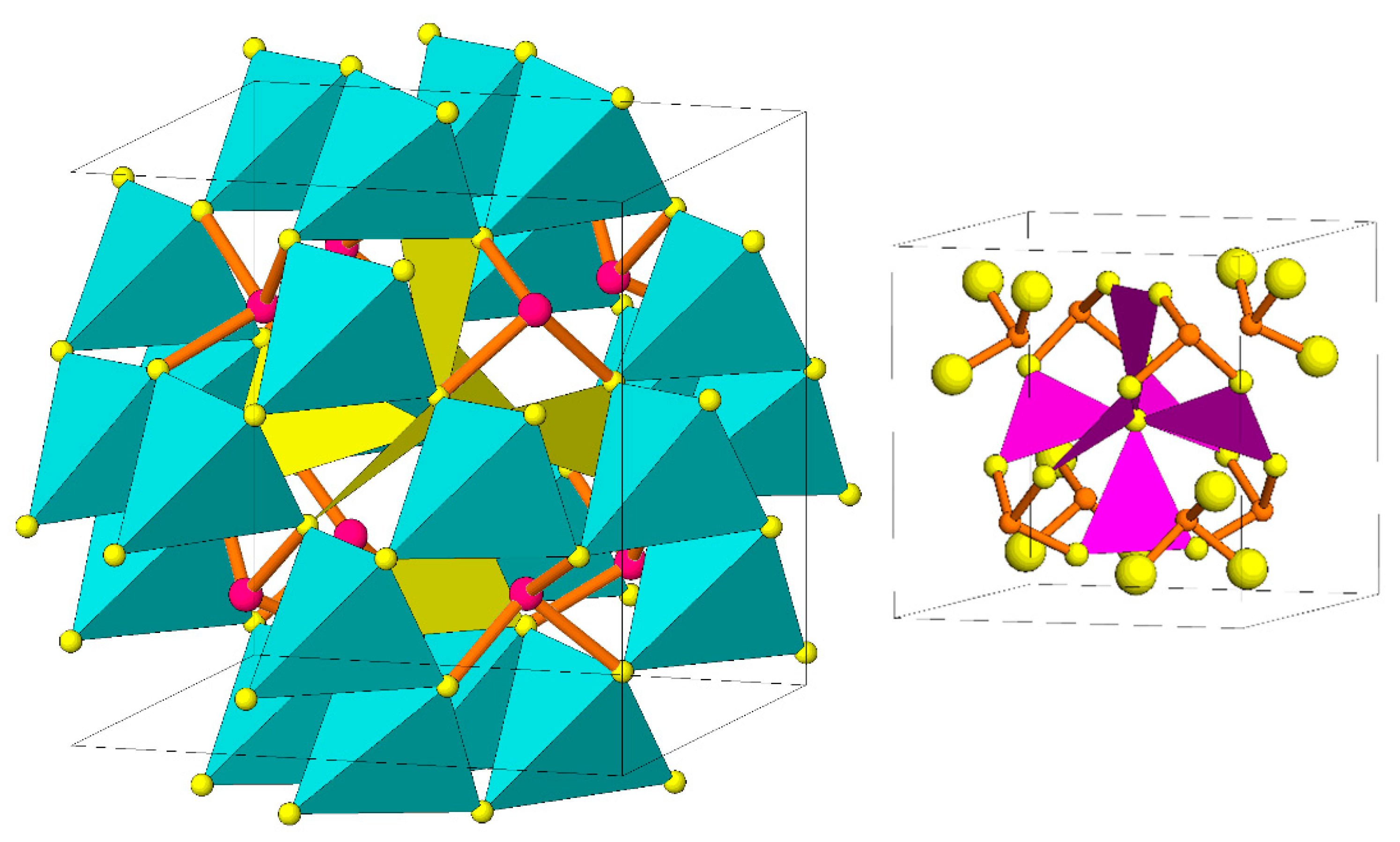
Figure 1.
Crystal structure of tetrahedrite–tennantite. MeS4 coordination tetrahedra (light blue) and majority of the (Cu,Ag)S3 coordination triangles (yellow) are shown in polyhedral representation, the Sb(As)S3 coordination pyramids as cation-anion bonds. Note filling of truncated-tetrahedron cavities in the tetrahedral framework by “spinners” composed of triangular co-ordinations. Inset: “spinner” of (Cu,Ag)S3 coordination triangles with (Sb,As)S3 coordination pyramids surrounding spinner cavity.

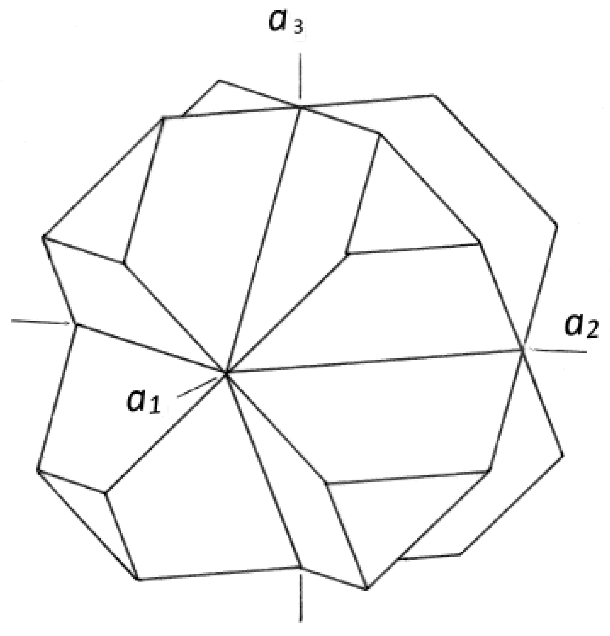
Figure 2.
Interpenetration twin of tetrahedrite by reflection on m‖(100). Twin symmetry elements are m‖(001), 4‖[100], 2‖[110], and inversion center.
Figure 2.
Interpenetration twin of tetrahedrite by reflection on m‖(100). Twin symmetry elements are m‖(001), 4‖[100], 2‖[110], and inversion center.

Figure 3.
A single one-tetrahedron-thick (111) order–disorder OD layer of the tetrahedrite structure from Figure 1. Only the tetrahedral framework is shown. Tetrahedra present in the given layer are given in bold outlines, on a background of the net of virtual tetrahedron bases. Triangular openings of the six-member tetrahedron rings are filled (and their shape constrained) by Sb(As)S3 coordination pyramids (not shown). The surrounding “empty” space of virtual tetrahedron bases represents different sections of the structure cavities which contain corresponding portions of the “spinners” with triangular Cu(Ag) coordinations (not drawn).

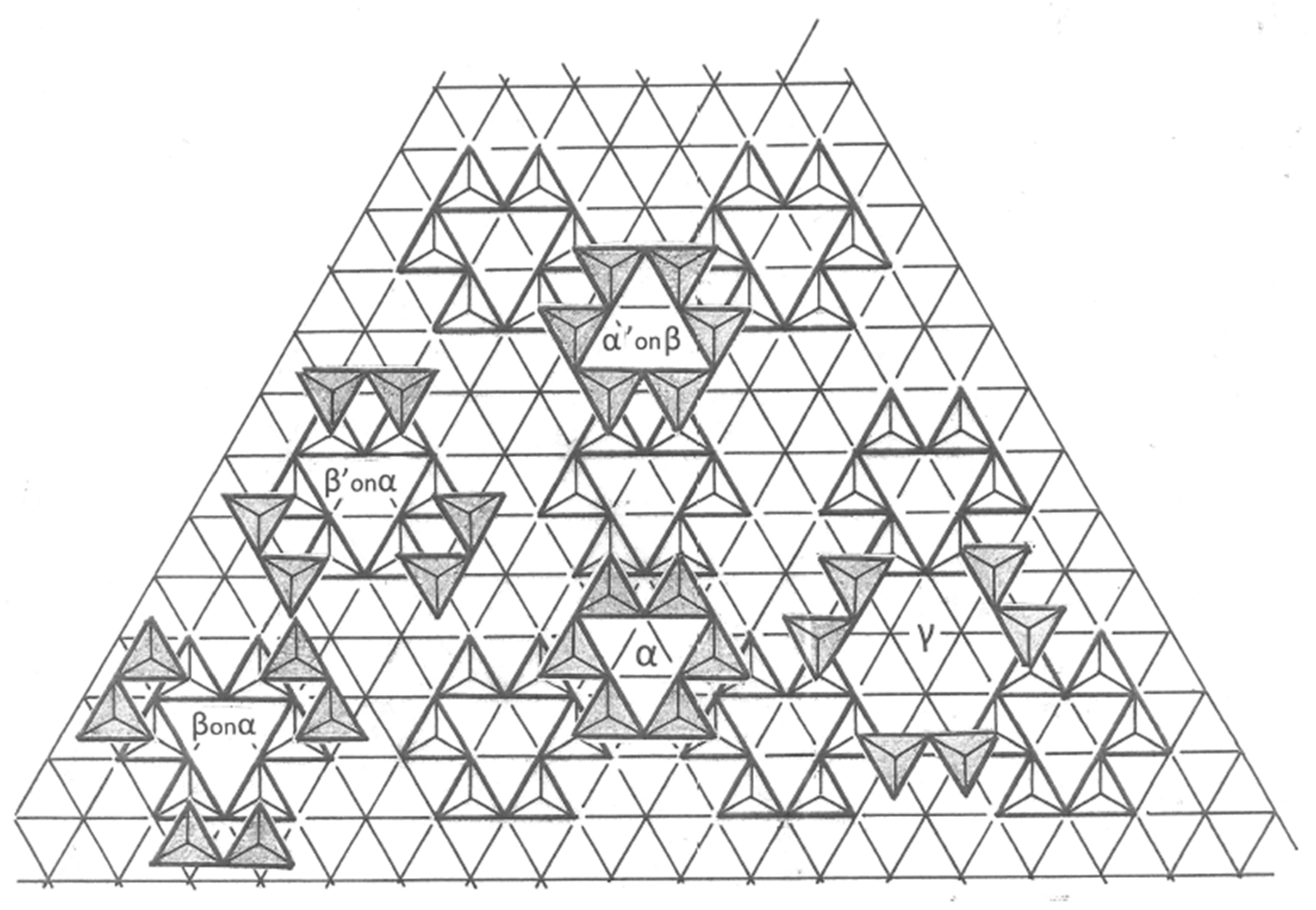
Figure 4.
The truncated-tetrahedron cavity of the structural framework encompasses four consecutive OD layers (two of which are shared with the preceding and the following cavity). The corresponding configurations from one blown-out cavity are denoted as α, β, γ, α; then, the sequence repeats. Lateral shifts in the depicted sequence simulate those needed for vertex-fitting.

Figure 5.
Tetrahedron-fit and vertex sharing of individual configurations from two (111) layers immediately following one another; the configurations are enumerated in the text. Configurations α, β, and γ for the unrotated layers are shown at the bottom of the figure, whereas stacking of α and β configurations for sequences which involve 180° rotation of consecutive layers are shown above them and are indicated by priming of the symbols.

Figure 6.
A two-layer sequence, with unrotated sequence of OD layers in the lower portion of the figure, and a 180°-rotated patch of the second (111) layer of tetrahedra in the upper portion of the figure. Incoherence between these two patches when they meet is accentuated in the right-hand central portions of the figure. Simplified symbols of symmetry operations indicate the reflection planes m in the individual OD layer, tied with the n-glide planes of the OD type (see full characterization in the text) for the unrotated layer pair, and the OD-type c-glide plane, and the corresponding 22 screw-axis, for the sequence with rotated OD layers.

Publisher’s Note: MDPI stays neutral with regard to jurisdictional claims in published maps and institutional affiliations. |
© 2021 by the author. Licensee MDPI, Basel, Switzerland. This article is an open access article distributed under the terms and conditions of the Creative Commons Attribution (CC BY) license (http://creativecommons.org/licenses/by/4.0/).
Share and Cite
MDPI and ACS Style
Makovicky, E. Twinning of Tetrahedrite—OD Approach. Minerals 2021, 11, 170. https://0-doi-org.brum.beds.ac.uk/10.3390/min11020170
AMA Style
Makovicky E. Twinning of Tetrahedrite—OD Approach. Minerals. 2021; 11(2):170. https://0-doi-org.brum.beds.ac.uk/10.3390/min11020170
Chicago/Turabian StyleMakovicky, Emil. 2021. "Twinning of Tetrahedrite—OD Approach" Minerals 11, no. 2: 170. https://0-doi-org.brum.beds.ac.uk/10.3390/min11020170
Note that from the first issue of 2016, this journal uses article numbers instead of page numbers. See further details here.