
Enhanced Reactant Distribution in Redox Flow Cells


School of Mechanical and Manufacturing Engineering, UNSW, Sydney, NSW 2052, Australia
*
Author to whom correspondence should be addressed.
Molecules 2019, 24(21), 3877; https://0-doi-org.brum.beds.ac.uk/10.3390/molecules24213877
Submission received: 3 October 2019
/
Revised: 23 October 2019
/
Accepted: 24 October 2019
/
Published: 28 October 2019
(This article belongs to the Special Issue Advances in Electrochemical Energy Storage Devices)
Abstract
:Redox flow batteries (RFBs), provide a safe and cost-effective means of storing energy at grid-scale, and will play an important role in the decarbonization of global electricity networks. Several approaches have been explored to improve their efficiency and power density, and recently, cell geometry modification has shown promise in efforts to address mass transport limitations which affect electrochemical and overall system performance. Flow-by electrode configurations have demonstrated significant power density improvements in laboratory testing, however, flow-through designs with conductive felt remain the standard at commercial scale. Concentration gradients exist within these cells, limiting their performance. A new concept of redistributing reactants within the flow frame is introduced in this paper. This research shows a 60% improvement in minimum V3+ concentration within simulated vanadium redox flow battery (VRB/VRFB) cells through the application of static mixers. The enhanced reactant distribution showed a cell voltage improvement by reducing concentration overpotential, suggesting a pathway forward to increase limiting current density and cycle efficiencies in RFBs.
1. Introduction
The large-scale adoption of renewable energy around the world, required for the decarbonization of power generation, will demand grid-scale energy storage, increasingly in the form of batteries [1]. Batteries are particularly suited to managing distributed, dynamic supply and demand challenges, including variable generators and an increasing number of electric vehicles. Redox flow batteries (RFBs) offer independent power and capacity scaling, long lifetimes, and inherent safety advantages over lithium-ion systems. There is a range of chemistries under development, with an increased focus on organic electrolytes [2], however, all-vanadium redox flow batteries (VRFBs) are already being commercially exploited.
There are exceptions in the form of hybrid systems, however true redox flow batteries decouple power (kW/MW) from the capacity (kWh/MWh) by converting energy in cell stacks and storing energy in liquid electrolyte tanks. The active element or compound, vanadium in the case of VRFBs, reacts while flowing through porous conductive carbon materials within two half-cells separated by a micro-porous separator or ion-selective membrane. Adequate local availability of reactants is essential for reliable and efficient charge and discharge processes, particularly at high and low states of charge (SOC). Material degradation can occur if the system is not managed properly, so flow rates are regulated, and power density is limited [3,4]. Power is a product of cell voltage and current density, making these important factors in RFB system costs [5] and operational efficiencies.
The cell voltage discussed here, , can be described in the form of Equation (1) [3] below:
where is the concentration overpotential, which can dominate when the concentration of a reactant in solution, , is low. In this case, the limiting current density, , can be expressed as shown in Equation (2) [4]:
Here, the local mass transfer coefficient, , is a function of velocity, , as shown in Equation (3) [4] below:
Despite extensive research and development work, the significance of electrolyte flow and the associated mass-transfer effects has not yet been adequately addressed [6]. Considerable attention has been devoted to material development, electrodes, and reaction mechanisms [7]. Where discussed, the primary focus of cell design has been on the use of flow fields, such as serpentine channels [8], however, critical challenges remain when these concepts are scaled to industrially relevant stack sizes [9]. Flow-through cells remain the standard for this reason, and large-area cells (some greater than 2.5 m2) are under development to deliver economies of scale [10].
Experimenting with large cells and assessing their internal state is challenging, making numerical modeling an essential tool for the analysis and optimization of these systems. Coupled fluid and electrochemistry models have been used in flow battery research since Shah and co-workers published their dynamic two-dimensional models [11,12,13]. Researchers have applied and developed these models for a range of purposes. A simplified stationary model was published by You et al. [14], then Ma and co-workers applied this to a three-dimensional format [15]. Other groups have included vanadium crossover and water transport through the membrane [16].
Simulation of innovative cell geometries, including trapezoidal [17], and radial designs [18] has recently shown the promise of design modifications to improve performance in flow-through cells. Studies have also explored reducing the cross-sectional area to provide increased electrode compression in addition to a higher flow rate towards the outlet [19]. Subsequent experimental testing on laboratory-scale cells demonstrated improved energy efficiencies with wedge-shaped cells, and a toroidal stack concept based on this concept has been presented [20]. An issue with flow-through cells that persists even with these new geometries, and others like the circular concept [21], is the problem of concentration gradients across the half-cell cross-section between the collector and the membrane [15].
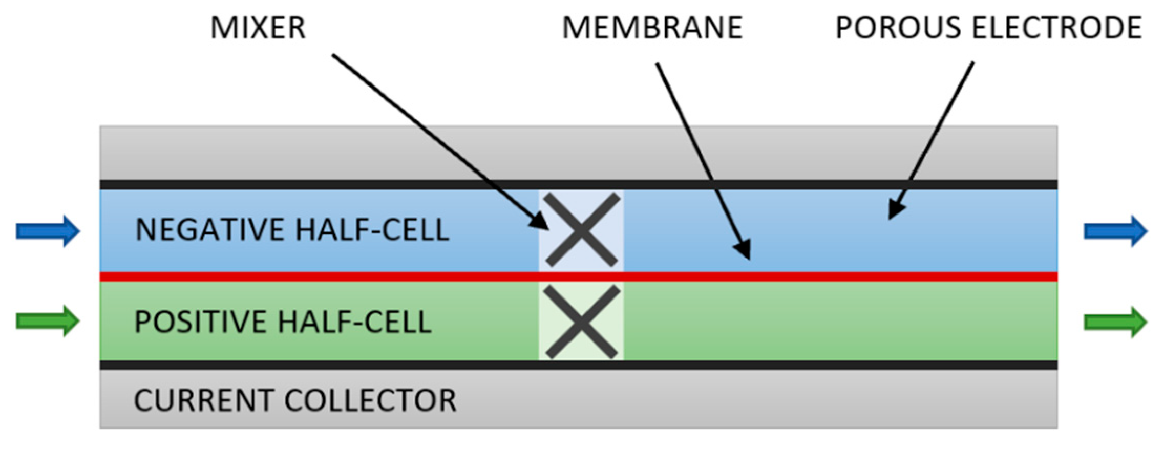
In the absence of turbulence or engineered architecture, such as the corrugated fluidic networks recently proposed [22], diffusion-limited flow conditions result in reactants being depleted close to boundaries. To address this, we propose applying static mixers, standard equipment in the process industries [23], to flow-through RFB cells using graphite felt electrodes. Mixing is essential in most industrial chemical processes, particularly where velocities are low in laminar flow regimes [24] as in VRFBs. Instead of inserting a mixer in a tube, this would involve adding a mixer (extended in width rather than length) into a gap in the porous electrode material in each half-cell of flow battery as shown in Figure 1.
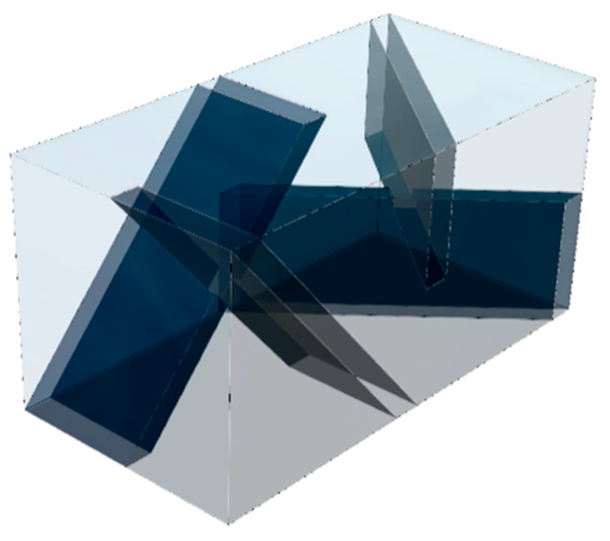
Static mixers have previously been used in experiments with VRFBs, and were found to reduce mass-transfer limitations, however the work focused on improving performance with slurry electrodes by enabling better charge transfer with particles [25]. Helical mixers, such as the KenicsTM mixer and the conductive mixers used for the slurry electrodes, are commonly found in round pipes and have been studied quite extensively [24,26,27,28]. This style provides flow division and radial mixing however is more challenging to optimize for the thinner rectangular geometry used in efficient stacks. For this reason, a blade-style, low-pressure drop (LPD) type mixer was generated as a starting point for this study. An inline mixer is generally composed of a series of baffle elements, an approach we have applied in this work. A two-element design is shown in Figure 2.
This geometry and others were simulated in a thin (2.5 mm unit-width) section of a flow cell, with symmetry applied to the side boundaries, using validated models with published parameters. In contrast to the mixers used with slurry electrodes [25], the mixers in this research are non-conductive to promote enhanced reactant distribution in the porous media. Results show improved performance when compared to conventional geometry without a mixer during charging at high current density.
2. Results
Initial tests were conducted with unit-width negative half-cells by replacing 10% of the porous electrode volume with a mixer. The blade elements of the mixer were then duplicated and rotated to generate geometries of two- and three-element mixers in addition to the single element case. The multi-element domains were longer as the variables were defined in relative terms. 160 mA/cm2 current density was applied through the collector boundary to an electrolyte with an inlet concentration of 90% SOC at a flow rate fixed at 5 stoich. Results in comparison to a conventional reference case under the same conditions are shown in Table 1.
Where the improvement in the minimum V3+ concentration within the half-cell domain was calculated as shown below in Equation (4):
The improvement in minimum concentration with a third mixer element was insignificant, so the two-element geometry was used in subsequent simulations. The impact of the mixer location was then assessed in 300 mm long half-cells, representative of a 900 cm2 cell, where the 5 mm long mixer replaces 1.7% of the electrode volume. Current density and flow rate were defined as before, at 160 mA/cm2 and 5 stoich. The results are shown in Table 2.
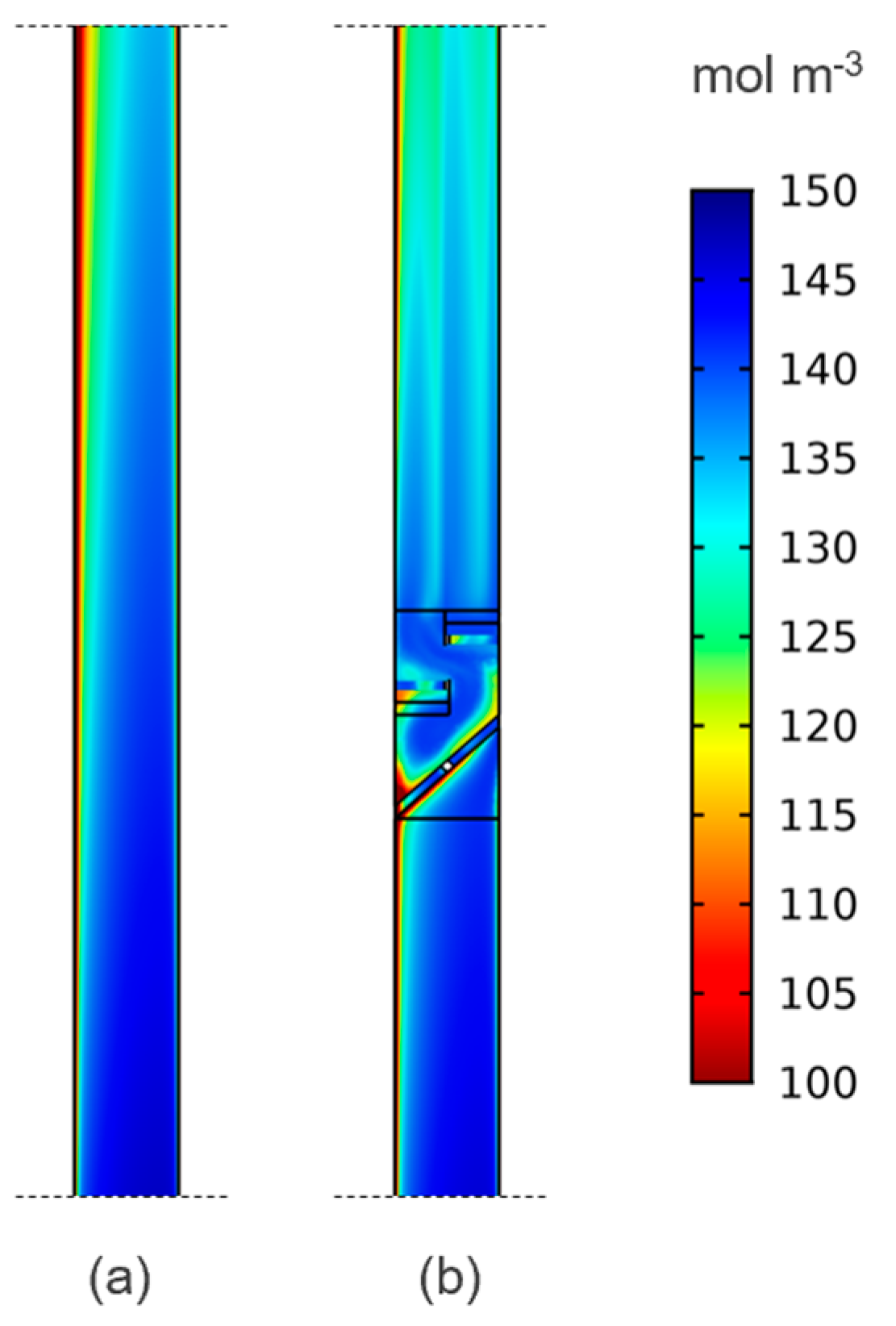
The mid-length position clearly offers the highest improvement when compared to the reference case. The mechanism for the improvement with multiple elements is seen in Figure 3, where the mixer is clearly shown to re-distribute reactants inside the half-cell.
This translates through to the outlet boundary, as shown in Figure 4, where the boundary layers are disrupted, and the bulk of the electrolyte is better utilized. This means a higher limiting current density for the same applied conditions, as this is directly proportional to the reactant concentration.
3. Discussion
Simulations for a unit-width slice of a 900 cm2 single cell showed a 1% improvement in cell voltage when compared to the reference geometry without a mixer. This is small, but a similar magnitude of improvement was seen with wedge-shaped cells applying reducing electrode compression [19], resulting in a 15% increase in energy efficiency during cycling experiments [20]. It is also worth noting that this was achieved while removing 1.7% of the porous electrode, rather than increasing current collector surface area with conductive mixers as applied to slurry electrodes [25]. The conductive helical mixers used in that study also delivered improved mass transport, however, the energy efficiency of thicker slurry cells remains lower than the thinner contemporary commercial stacks with carbon felt, which is the proposed application for the mixers in this study.
Table 3 shows that the pressure drop relative to a traditional geometry is higher at increased flow rates, which is expected, a mixer does have an energy cost. It is noted, however, that based on the improved reactant distribution, the flow rate could be reduced for the same current and the mixer geometry can also be optimized to improve mixing while reducing flow resistance. This could also be countered by applying varied compression over the length of the cell, which has been shown to reduce pressure drop and improve electrochemical performance [19,20].
Membrane punctures could conceivably be an issue with combinations of a hard mixer and thin membranes, as even carbon fibers can protrude [29]. The risk from the mixer itself, however, is mitigated by the surrounding compressed porous material, which would prevent excessive contact pressure between the mixer and the membrane. The separator could also be reinforced, particularly in larger cells, and the mixer could be produced from a soft material. Prototype two-element mixers additively manufactured in rigid Accura® Xtreme™ and flexible VisiJet® CE-NT material are shown below in Figure 5. The rigid stereolithography (SLA) material has a shore hardness of 86D [30] while the flexible material jetting (MJP) polymer is 27-33A [31]. Selecting appropriate membrane and mixer materials for an industrial flow battery application is complex and will depend on a range of factors, including commercial decisions on cost and durability, as discussed at the International Flow Battery Forum [32].
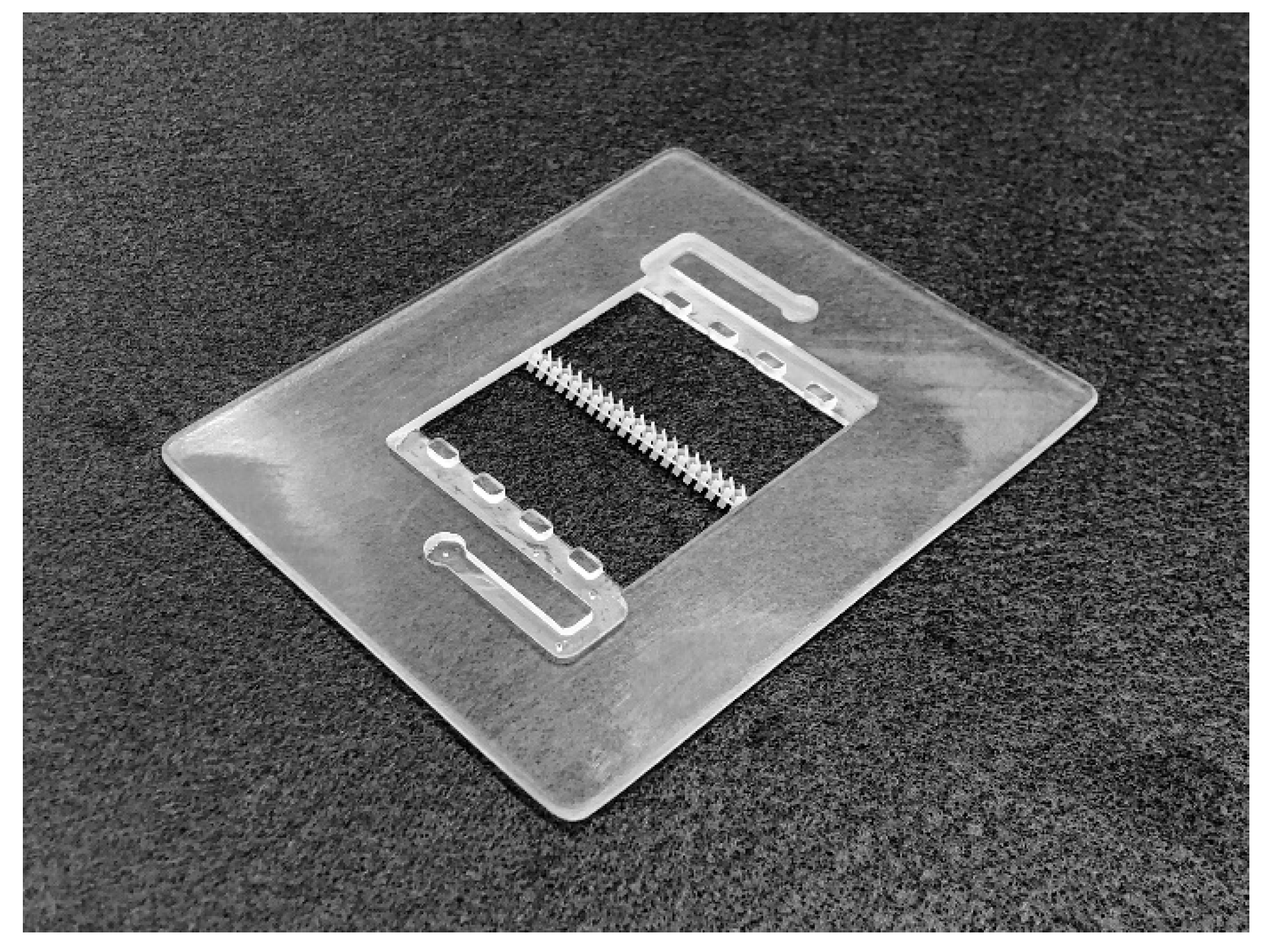
Electrode intrusion could also affect the performance, however, the impact is likely to be positive due to the increased reaction volume [33]. Further research will be required to assess the impact of this on mixing performance and will seek to demonstrate this concept experimentally in laboratory-scale cells, and Figure 6 shows preliminary work to this end with the prototype two-element mixer positioned in a flow frame manufactured with the same 3D printing process. A longer cell is planned to better examine the effects expected in large stacks, where gradients are more pronounced.
Future work will also explore the combination of this innovation with wedge-shaped cells–the two innovations are not mutually exclusive, and as discussed above the combination of both promises added benefits for redox flow batteries. Investigation of other geometries and conductive materials, like those used with slurry electrodes [25], is also to be conducted. Simulation provides an accessible means to explore these options and complement laboratory cycling experiments, which can also assess the impact of this innovation on flow cell durability.
In summary, more research is required to assess and optimize all the coupled variables, however the results presented here suggest this would be worthwhile. The addition of a mixer in a redox flow battery cell has potential to improve the electrochemical performance, particularly in the larger cells that are used in commercial systems.
4. Materials and Methods
The methodology for this work was based on techniques applied in previously published research [18,19]. A concise overview and key parameters are provided here, further details are available in the references.
Governing equations were applied based on the approach developed by Shah et al. [11] and You et al. [14]. Ion flux is described by the Nernst-Planck equations and the Butler-Volmer law is used to define electrode reaction kinetics, while Darcy’s law was applied to give the velocity in the porous electrode. Some elements of the model were taken from Knehr et al. [16] in relation to fluid parameters and the treatment of the boundaries between the membrane and electrodes. Selected SOC values were simulated for model validation, as described by You et al. and Zheng et al. [34].
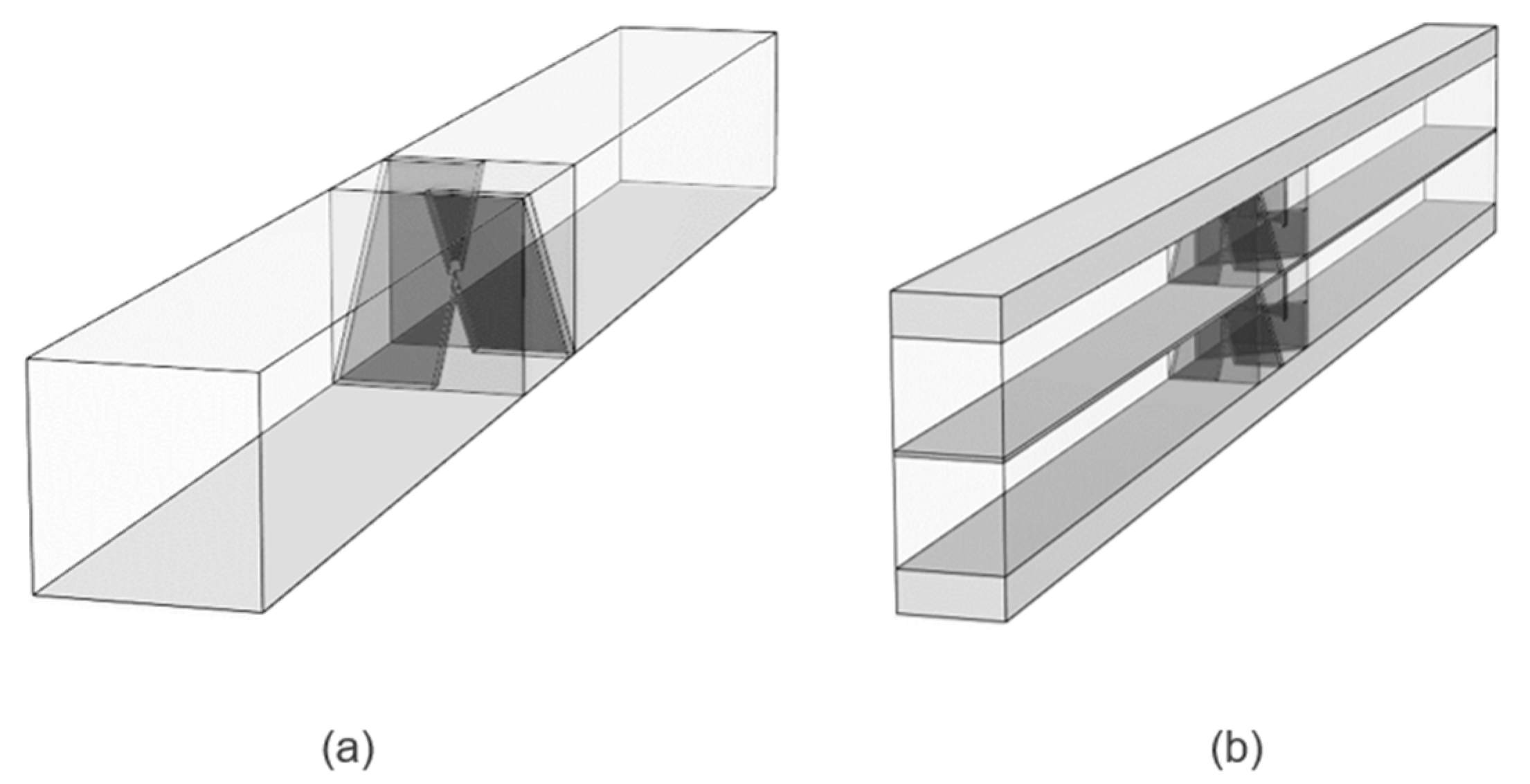
Simplified half-cell models (one geometry shown in Figure 7a) were used for the initial studies to assess the impact of varying flow rate, the number of mixer elements, and the location of the mixer in the cell. Full-cell models (geometry with mixers, truncated for easy viewing, shown in Figure 7b) were used to assess the effect of the mixer on cell voltage. Symmetry boundaries were used on both sides of the unit-width geometry to minimize the computational domain.
Mapped meshes with elements biased towards the outlet and current collector boundaries were used for the conventional rectangular geometry without mixers. The volume surrounding the mixers was discretized with unstructured meshes. Mesh refinement studies were conducted to determine the required resolution to achieve convergence for minimum concentration values, which are dependent on both convective mass transfer and electrochemical processes. Numbers of elements in the order of 200,000 were found to provide acceptable resolution.
The coupled electrochemical and fluid models and were solved using the finite element method with software package COMSOL Multiphysics with the UNSW Sydney computational cluster, Katana. A combination of flow and current distribution interfaces were used to implement the convection-diffusion, general-form, and ordinary differential equations. Except where stated elsewhere, the general parameters shown in Table 4 were applied.
Inlet velocity was defined as a multiple of the stoichiometric requirement based on the applied current, which is a function of cell size and current density. Key parameters for positive and negative fluids are shown below in Table 5. The electrolyte is assumed to have constant physical properties.
Electrode and current collector properties are shown below in Table 6. The Carmen–Kozeny equation was used to define the permeability of the electrodes as a function of porosity.
Electrochemical properties used are summarised in Table 7 for reference. A Bruggeman correction was applied to diffusion coefficients and electrical conductivity parameters.
The full-cell model implemented here with parameters defined by You et al. [14], including a 140 mV voltage correction for considerations not included in the simplified model such as contact resistances, showed good agreement with the experimental data published in their work. The values did not vary significantly from those previously reported [19], with an average error of 1% and a maximum error of 3%. A comparison between the full-cell and half-cell models showed no significant difference in key values (maximum 0.2% variation for minimum V3+ concentration).
Performance parameters were obtained through post-processing in COMSOL. Derived values were introduced to provide the minimum V3+ concentration over the negative electrode cross-section. A boundary probe was used to obtain the electric potential on the current collector boundary on the positive half-cell. This boundary is defined with an electrode current boundary condition set at the applied average current density, while the negative is defined as electric ground. Differential pressure was obtained by subtracting the average absolute pressure at the inlet from the absolute pressure at the outlet boundary.
Author Contributions
Conceptualization, N.G. and D.F.K.; data curation, N.G.; formal analysis, N.G.; investigation, N.G.; methodology, N.G. and D.F.K.; resources, V.T. and C.M.; software, N.G.; supervision, V.T. and C.M.; validation, N.G.; visualization, N.G.; writing—original draft, N.G.; writing—review & editing, D.F.K., V.T. and C.M.
Funding
The first author acknowledges the support of an Australian Government Research Training Program (RTP) Scholarship.
Conflicts of Interest
The authors declare no conflict of interest.
References
- BloombergNEF, Energy Storage Investments Boom As Battery Costs Halve in the Next Decade, Bloomberg. 2019. Available online: https://about.bnef.com/blog/energy-storage-investments-boom-battery-costs-halve-next-decade/ (accessed on 21 September 2019).
- Ye, R.; Henkensmeier, D.; Yoon, S.J.; Huang, Z.; Kim, D.K.; Chang, Z.; Kim, S.; Chen, R. Redox Flow Batteries for Energy Storage: A Technology Review. J. Electrochem. Energy Convers. Storage 2017, 15, 010801. [Google Scholar] [CrossRef]
- Skyllas-Kazacos, M.; Menictas, C.; Lim, T.M. Redox flow batteries for medium- to large-scale energy storage. In Electricity Transmission, Distribution and Storage Systems; Melhem, Z., Ed.; Woodhead Publishing: Cambridge, UK, 2013; pp. 398–441. [Google Scholar]
- Tang, A.; Bao, J.; Skyllas-Kazacos, M. Studies on pressure losses and flow rate optimization in vanadium redox flow battery. J. Power Sources 2014, 248, 154–162. [Google Scholar] [CrossRef]
- Noack, J.; Roznyatovskaya, N.V.; Gurieff, N.; Menictas, C.; Tübke, J.; Skyllas-kazacos, M. Current Development Trends and Challenges for Redox-Flow Batteries. In Proceedings of the ModVal 2018, Aarau, Switzerland, 12–13 April 2018. [Google Scholar] [CrossRef]
- Arenas, L.F.; De León, C.P.; Walsh, F.C. Redox flow batteries for energy storage: Their promise, achievements and challenges. Curr. Opin. Electrochem. 2019, 16, 117–126. [Google Scholar] [CrossRef]
- Kim, K.J.; Park, M.-S.; Kim, Y.-J.; Kim, J.H.; Dou, S.X.; Skyllas-Kazacos, M. A technology review of electrodes and reaction mechanisms in vanadium redox flow batteries. J. Mater. Chem. A 2015, 3, 16913–16933. [Google Scholar] [CrossRef]
- Aaron, D.; Liu, Q.; Tang, Z.; Grim, G.; Papandrew, A.; Turhan, A.; Zawodzinski, T.; Mench, M. Dramatic performance gains in vanadium redox flow batteries through modified cell architecture. J. Power Sources 2012, 206, 450–453. [Google Scholar] [CrossRef]
- Ke, X.; Prahl, J.M.; Alexander, J.I.D.; Wainright, J.S.; Zawodzinski, T.A.; Savinell, R.F. Rechargeable redox flow batteries: Flow fields, stacks and design considerations. Chem. Soc. Rev. 2018, 47, 8721–8743. [Google Scholar] [CrossRef]
- Minke, C.; Kunz, U.; Turek, T. Techno-economic assessment of novel vanadium redox flow batteries with large-area cells. J. Power Sources 2017, 361, 105–114. [Google Scholar] [CrossRef]
- Shah, A.A.; Watt-Smith, M.; Walsh, F. A dynamic performance model for redox-flow batteries involving soluble species. Electrochim. Acta 2008, 53, 8087–8100. [Google Scholar] [CrossRef] [Green Version]
- Shah, A.A.; Al-Fetlawi, H.; Walsh, F. Dynamic modelling of hydrogen evolution effects in the all-vanadium redox flow battery. Electrochim. Acta 2010, 55, 1125–1139. [Google Scholar] [CrossRef]
- Shah, A.A.; Tangirala, R.; Singh, R.; Wills, R.G.A.; Walsh, F.C. A Dynamic Unit Cell Model for the All-Vanadium Flow Battery. J. Electrochem. Soc. 2011, 158, 671. [Google Scholar] [CrossRef]
- You, D.; Zhang, H.; Chen, J. A simple model for the vanadium redox battery. Electrochim. Acta 2009, 54, 6827–6836. [Google Scholar] [CrossRef]
- Ma, X.; Zhang, H.; Xing, F. A three-dimensional model for negative half cell of the vanadium redox flow battery. Electrochim. Acta 2011, 58, 238–246. [Google Scholar] [CrossRef]
- Knehr, K.W.; Agar, E.; Dennison, C.R.; Kalidindi, A.R.; Kumbur, E.C.; Dennison, C. A Transient Vanadium Flow Battery Model Incorporating Vanadium Crossover and Water Transport through the Membrane. J. Electrochem. Soc. 2012, 159, A1446–A1459. [Google Scholar] [CrossRef]
- Yue, M.; Zheng, Q.; Xing, F.; Zhang, H.; Li, X.; Ma, X. Flow field design and optimization of high power density vanadium flow batteries: A novel trapezoid flow battery. AIChE J. 2017, 64, 782–795. [Google Scholar] [CrossRef]
- Gurieff, N.; Cheung, C.; Timchenko, V.; Menictas, C. Performance enhancing stack geometry concepts for redox flow battery systems with flow through electrodes. J. Energy Storage 2019, 22, 219–227. [Google Scholar] [CrossRef]
- Gurieff, N.; Timchenko, V.; Menictas, C. Variable Porous Electrode Compression for Redox Flow Battery Systems. Batteries 2018, 4, 53. [Google Scholar] [CrossRef]
- Gurieff, N.; Menictas, C.; Timchenko, V.; Skyllas-Kazacos, M.; Noack, J. Performance enhancing stack geometry concepts. In Proceedings of the International Flow Battery Forum, Lyon, France, 9–11 July 2019. [Google Scholar] [CrossRef]
- Zheng, Q.; Xing, F.; Li, X.; Liu, T.; Lai, Q.; Ning, G.; Zhang, H. Dramatic performance gains of a novel circular vanadium flow battery. J. Power Sources 2015, 277, 104–109. [Google Scholar] [CrossRef]
- Lisboa, K.M.; Marschewski, J.; Ebejer, N.; Ruch, P.; Cotta, R.M.; Michel, B.; Poulikakos, D. Mass transport enhancement in redox flow batteries with corrugated fluidic networks. J. Power Sources 2017, 359, 322–331. [Google Scholar] [CrossRef]
- Thakur, R.; Vial, C.; Nigam, K.; Nauman, E.; Djelveh, G.; Vial, C. Static Mixers in the Process Industries—A Review. Chem. Eng. Res. Des. 2003, 81, 787–826. [Google Scholar] [CrossRef]
- Hobbs, D.; Muzzio, F. Reynolds number effects on laminar mixing in the Kenics static mixer. Chem. Eng. J. 1998, 70, 93–104. [Google Scholar] [CrossRef]
- Percin, K.; Rommerskirchen, A.; Sengpiel, R.; Gendel, Y.; Wessling, M. 3D-printed conductive static mixers enable all-vanadium redox flow battery using slurry electrodes. J. Power Sources 2018, 379, 228–233. [Google Scholar] [CrossRef] [Green Version]
- Hobbs, D.; Muzzio, F. The Kenics static mixer: A three-dimensional chaotic flow. Chem. Eng. J. 1997, 67, 153–166. [Google Scholar] [CrossRef]
- Hobbs, D.; Swanson, P.; Muzzio, F. Numerical characterization of low Reynolds number flow in the Kenics static mixer. Chem. Eng. Sci. 1998, 53, 1565–1584. [Google Scholar] [CrossRef]
- Kumar, V.; Shirke, V.; Nigam, K. Performance of Kenics static mixer over a wide range of Reynolds number. Chem. Eng. J. 2008, 139, 284–295. [Google Scholar] [CrossRef]
- Bauer, B.; Klicpera, T. Practical limits of membrane’s thickness in all-VRFB application. In Proceedings of the International Flow Battery Forum, Lyon, France, 9–11 July 2019. [Google Scholar]
- 3D Systems, Accura Xtreme (SLA)—Technical Specifications. 2019. Available online: https://www.3dsystems.com/materials/accura-xtreme/tech-specs (accessed on 17 October 2019).
- 3D Systems, VisiJet CE-NT (MJP)—Technical Specifications. 2019. Available online: https://au.3dsystems.com/materials/visijet-ce-nt-elastomeric-natural/tech-specs (accessed on 17 October 2019).
- Newbloom, G.; Pickett, P.; Lenz, O. Flow battery cost reductions enabled by membrane innovations. In Proceedings of the International Flow Battery Forum, Lyon, France, 9–11 July 2019. [Google Scholar]
- Wang, Q.; Qu, Z.; Jiang, Z.; Yang, W. Numerical study on vanadium redox flow battery performance with non-uniformly compressed electrode and serpentine flow field. Appl. Energy 2018, 220, 106–116. [Google Scholar] [CrossRef]
- Zheng, Q.; Zhang, H.; Xing, F.; Ma, X.; Li, X.; Ning, G. A three-dimensional model for thermal analysis in a vanadium flow battery. Appl. Energy 2014, 113, 1675–1685. [Google Scholar] [CrossRef]
Sample Availability: Samples of the compounds are not available from the authors. |
Figure 1.
Single-cell diagram showing mixers at halfway point in each half-cell. Note there is a gap in the porous material in the mixer volume.
Figure 1.
Single-cell diagram showing mixers at halfway point in each half-cell. Note there is a gap in the porous material in the mixer volume.

Figure 2.
Computer Aided Design (CAD) render of the two-element blade-style mixer used in this study. This configuration has a volume envelope of 2.5 × 2.5 × 5.0 mm.
Figure 2.
Computer Aided Design (CAD) render of the two-element blade-style mixer used in this study. This configuration has a volume envelope of 2.5 × 2.5 × 5.0 mm.

Figure 3.
Concentration (mol m−3) of V3+ on cross-section plane at one-third depth (halfway across a mixer blade) for reference (a) and two-element mixer (b) cases showing enhanced reactant distribution.
Figure 3.
Concentration (mol m−3) of V3+ on cross-section plane at one-third depth (halfway across a mixer blade) for reference (a) and two-element mixer (b) cases showing enhanced reactant distribution.

Figure 4.
Concentration (mol m−3) of V3+ at the outlet boundary for reference (a) and two-element mixer (b) cases showing improved electrolyte utilization during charging at high current density.
Figure 4.
Concentration (mol m−3) of V3+ at the outlet boundary for reference (a) and two-element mixer (b) cases showing improved electrolyte utilization during charging at high current density.

Figure 5.
Prototype two-element mixers additively manufactured using (a) stereolithography (SLA) in rigid form and (b) material jetting (MJP) with flexible material.
Figure 5.
Prototype two-element mixers additively manufactured using (a) stereolithography (SLA) in rigid form and (b) material jetting (MJP) with flexible material.

Figure 6.
Prototype mixer in a 25 cm2 flow frame. Both parts were additively manufactured using stereolithography (SLA), in rigid grey and transparent material, respectively.
Figure 6.
Prototype mixer in a 25 cm2 flow frame. Both parts were additively manufactured using stereolithography (SLA), in rigid grey and transparent material, respectively.

Figure 7.
CAD renders of (a) unit-width half-cell with a single element mixer and (b) a shortened unit-width full-cell with two-element blade-style mixers in both half-cells.
Figure 7.
CAD renders of (a) unit-width half-cell with a single element mixer and (b) a shortened unit-width full-cell with two-element blade-style mixers in both half-cells.


Table 1.
Improvement in minimum V3+ concentration with one-, two-, and three-element mixers relative to conventional geometry.
Table 1.
Improvement in minimum V3+ concentration with one-, two-, and three-element mixers relative to conventional geometry.
| Geometry | Concentration Improvement |
|---|---|
| 1 Element | 7% |
| 2 Element | 41% |
| 3 Element | 42% |
Table 2.
Improvement in minimum V3+ concentration with two-element mixers at three different locations relative to conventional geometry.
Table 2.
Improvement in minimum V3+ concentration with two-element mixers at three different locations relative to conventional geometry.
| Location | Concentration Improvement |
|---|---|
| 1/3 Position | 36% |
| 1/2 Position | 60% |
| 2/3 Position | 44% |
Table 3.
Change in pressure drop across a 300 mm long unit-width half-cell relative to conventional geometry over a range of flow rates defined as a multiple of the stoichiometric requirement (stoich).
Table 3.
Change in pressure drop across a 300 mm long unit-width half-cell relative to conventional geometry over a range of flow rates defined as a multiple of the stoichiometric requirement (stoich).
| Flow Rate | Pressure Drop |
|---|---|
| 1 | 1% |
| 5 | −2% |
| 10 | −4% |
Table 4.
General operating parameters.
| Parameter | Symbol | Value | Unit |
|---|---|---|---|
| Outlet pressure | 0 | Pa | |
| Temperature | 293.15 | K | |
| Current density | 160 | mA cm−2 | |
| State of Charge | 90 | - | |
| Half-cell electrode thickness | h | 2.5 × 10⁻³ | m |
| Domain width | w | 2.5 × 10⁻³ | m |
| Current collector thickness | h | 1.0 × 10⁻³ | m |
| Membrane thickness | 0.1 × 10⁻³ | m |
Table 5.
Fluid model parameters from Knehr et al. [16].
Table 5.
Fluid model parameters from Knehr et al. [16].
| Parameter | Symbol | Value | Unit |
|---|---|---|---|
| Dynamic viscosity (negative electrolyte) | 0.0025 | Pa s | |
| Dynamic viscosity (positive electrolyte) | 0.005 | Pa s | |
| Density (negative electrolyte) | 1300 | kg m−3 | |
| Density (positive electrolyte) | 1350 | kg m−3 |
Table 6.
Electrode and current collector parameters from Knehr et al. [16].
Table 6.
Electrode and current collector parameters from Knehr et al. [16].
| Parameter | Symbol | Value | Unit |
|---|---|---|---|
| Conductivity of current collector | 1000 | S m−1 | |
| Conductivity of electrode | 66.7 | S m−1 | |
| Porosity | 0.929 | - | |
| Mean pore radius | 50.3 × 10⁻⁶ | m | |
| Kozeny–Carman constant | 180 | - |
Table 7.
Electrochemical parameters from You et al. [14].
Table 7.
Electrochemical parameters from You et al. [14].
| Parameter | Symbol | Value | Unit |
|---|---|---|---|
| V2+ diffusion coefficient | 2.4 × 10⁻¹⁰ | m2 s−1 | |
| V3+ diffusion coefficient | 2.4 × 10⁻¹⁰ | m2 s−1 | |
| VO2+ diffusion coefficient | 3.9 × 10⁻¹⁰ | m2 s−1 | |
| VO2+ diffusion coefficient | 3.9 × 10⁻¹⁰ | m2 s−1 | |
| Proton diffusion coefficient | 9.312 × 10⁻⁹ | m2 s−1 | |
| Initial vanadium concentration | 1500 | mol m−3 | |
| Initial proton concentration (negative) | 4500 | mol m−3 | |
| Initial proton concentration (positive) | 6000 | mol m−3 | |
| Standard reaction rate constant (negative) | 1.7 × 10⁻⁷ | m s−1 | |
| Standard reaction rate constant (positive) | 6.8 × 10⁻⁷ | m s−1 | |
| Anodic transfer coefficient | 0.5 | – | |
| Cathodic transfer coefficient | 0.5 | – | |
| Equilibrium potential: V2+/V3+ | −0.255 | V | |
| Equilibrium potential: VO2+/VO2+ | 1.004 | V |
© 2019 by the authors. Licensee MDPI, Basel, Switzerland. This article is an open access article distributed under the terms and conditions of the Creative Commons Attribution (CC BY) license (http://creativecommons.org/licenses/by/4.0/).
Share and Cite
MDPI and ACS Style
Gurieff, N.; Keogh, D.F.; Timchenko, V.; Menictas, C. Enhanced Reactant Distribution in Redox Flow Cells. Molecules 2019, 24, 3877. https://0-doi-org.brum.beds.ac.uk/10.3390/molecules24213877
AMA Style
Gurieff N, Keogh DF, Timchenko V, Menictas C. Enhanced Reactant Distribution in Redox Flow Cells. Molecules. 2019; 24(21):3877. https://0-doi-org.brum.beds.ac.uk/10.3390/molecules24213877
Chicago/Turabian StyleGurieff, Nicholas, Declan Finn Keogh, Victoria Timchenko, and Chris Menictas. 2019. "Enhanced Reactant Distribution in Redox Flow Cells" Molecules 24, no. 21: 3877. https://0-doi-org.brum.beds.ac.uk/10.3390/molecules24213877