Article

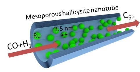
Ruthenium-Loaded Halloysite Nanotubes as Mesocatalysts for Fischer–Tropsch Synthesis

1
Gubkin University, 65 Leninsky Prosp., Moscow 119991, Russia
2
N.D. Zelinsky Institute of Organic Chemistry, 47 Leninsky Prosp, Moscow 119991, Russia
3
Institute for Micromanufacturing, Louisiana Tech University, 505 Tech Drive, Ruston, LA 71272, USA
*
Authors to whom correspondence should be addressed.
Submission received: 17 March 2020 / Revised: 6 April 2020 / Accepted: 10 April 2020 / Published: 11 April 2020
(This article belongs to the Special Issue Recent Research Advance in the Halloysite Nanotubes Field)

Abstract

:
Halloysite aluminosilicate nanotubes loaded with ruthenium particles were used as reactors for Fischer–Tropsch synthesis. To load ruthenium inside clay, selective modification of the external surface with ethylenediaminetetraacetic acid, urea, or acetone azine was performed. Reduction of materials in a flow of hydrogen at 400 °C resulted in catalysts loaded with 2 wt.% of 3.5 nm Ru particles, densely packed inside the tubes. Catalysts were characterized by N2-adsorption, temperature-programmed desorption of ammonia, transmission electron microscopy, X-ray fluorescence, and X-ray diffraction analysis. We concluded that the total acidity and specific morphology of reactors were the major factors influencing activity and selectivity toward CH4, C2–4, and C5+ hydrocarbons in the Fischer–Tropsch process. Use of ethylenediaminetetraacetic acid for ruthenium binding gave a methanation catalyst with ca. 50% selectivity to methane and C2–4. Urea-modified halloysite resulted in the Ru-nanoreactors with high selectivity to valuable C5+ hydrocarbons containing few olefins and a high number of heavy fractions (α = 0.87). Modification with acetone azine gave the slightly higher CO conversion rate close to 19% and highest selectivity in C5+ products. Using a halloysite tube with a 10–20-nm lumen decreased the diffusion limitation and helped to produce high-molecular-weight hydrocarbons. The extremely small C2–C4 fraction obtained from the urea- and azine-modified sample was not reachable for non-templated Ru-nanoparticles. Dense packing of Ru nanoparticles increased the contact time of olefins and their reabsorption, producing higher amounts of C5+ hydrocarbons. Loading of Ru inside the nanoclay increased the particle stability and prevented their aggregation under reaction conditions.

Graphical Abstract

1. Introduction

Global consumption of transportation fuels, lubricants, and chemicals amid the depletion of petroleum reserves is leading to a growing demand for alternative hydrocarbon sources. These non-petroleum feedstocks include natural gas and coal, as well as renewable biomass and urban wastes [1]. All of them can be converted into clean hydrocarbons via syngas production followed by Fischer–Tropsch synthesis (FTS).
Iron- and cobalt-based microcatalysts are currently used in commercial Fischer–Tropsch (FT) processes mainly due to their low cost and relatively high efficiency. However, ruthenium is known to be the most active catalyst which can work without promoters, and it typically produces heavier hydrocarbons [2,3]. Activity of ruthenium in CO hydrogenation depends on the particle size with 5–10-nm nanoparticles being the most active [4,5].
In recent years, nanostructured systems including those based on metal ruthenium were actively studied for their higher reaction rate and selectivity for the main products [6,7,8,9,10]. Commonly used supports for FT catalysts are silica, alumina, zirconia, and titanium oxide [5,11,12]. Alumina-supported catalysts could give higher ruthenium dispersion compared to a silica carrier, while SiO2-based catalysts are characterized by low acidity resulting in higher long-chain hydrocarbon selectivity [13]. For carbon nanotubes as a carrier in the Fischer–Tropsch synthesis, it was shown that placing metal particles inside the nanotubes leads to an increase in the efficiency of the catalysis [12,13,14,15].
Halloysite is a unique mineral that is formed by rolling of kaolin sheets into multiwalled mesoporous nanotubes [16]. The halloysite lumen’s surface is formed by alumina, and the outer tube’s surface contains silica. Such a structure allows for site-dependent chemistry exploiting a negatively charged outer surface and positive inner lumen. Low acidity is another property of halloysite that is important for FTS catalysts [5]. Recently, we showed that metal nanoparticles could be synthesized selectively inside halloysite using azines as complexing agents [17]. Ru loaded inside halloysite by complexation of RuCl3 with 1,2-bis(2-furylmethylene)hydrazine was found to be efficient in the hydrogenation of mono-aromatics [18,19,20]. No works were performed on the complexing agent’s effect on morphology, physico-chemical properties, and catalytic activity of ruthenium-loaded halloysite.
For the first time, we propose natural mesoporous halloysite clay nanotubes as a carrier for ruthenium-containing catalysts for producing hydrocarbons from synthesis gas (CO + H2). There was a previous study on halloysite-supported cobalt Fischer–Tropsch synthesis catalysts [21]. We showed that Ru/halloysite core–shell nanocatalysts for CO hydrogenation allowed for much higher catalytic efficiency. We also demonstrated how the choice of complexing agents affects activity of halloysite-based catalysts in Fischer–Tropsch synthesis.

2. Results and Discussion

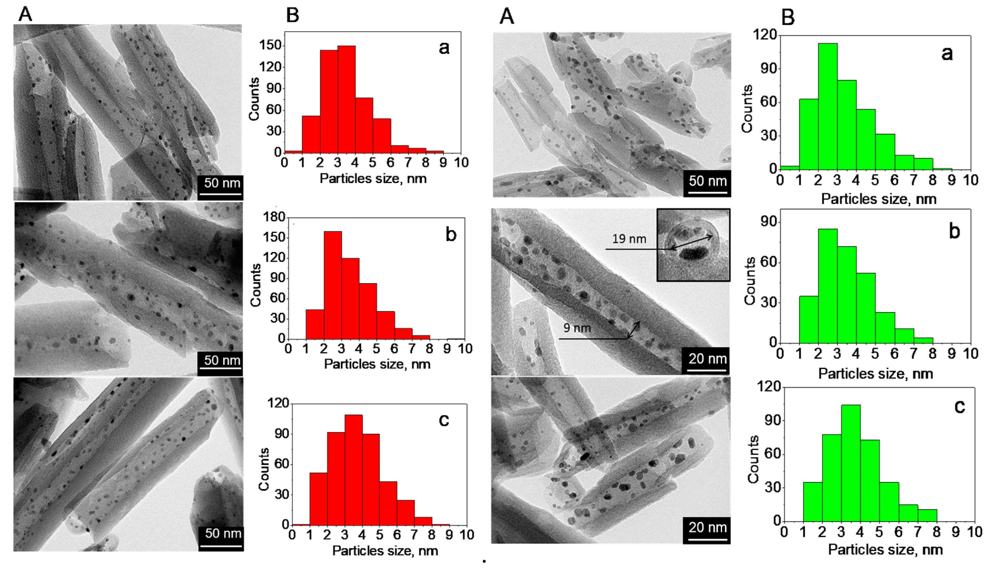
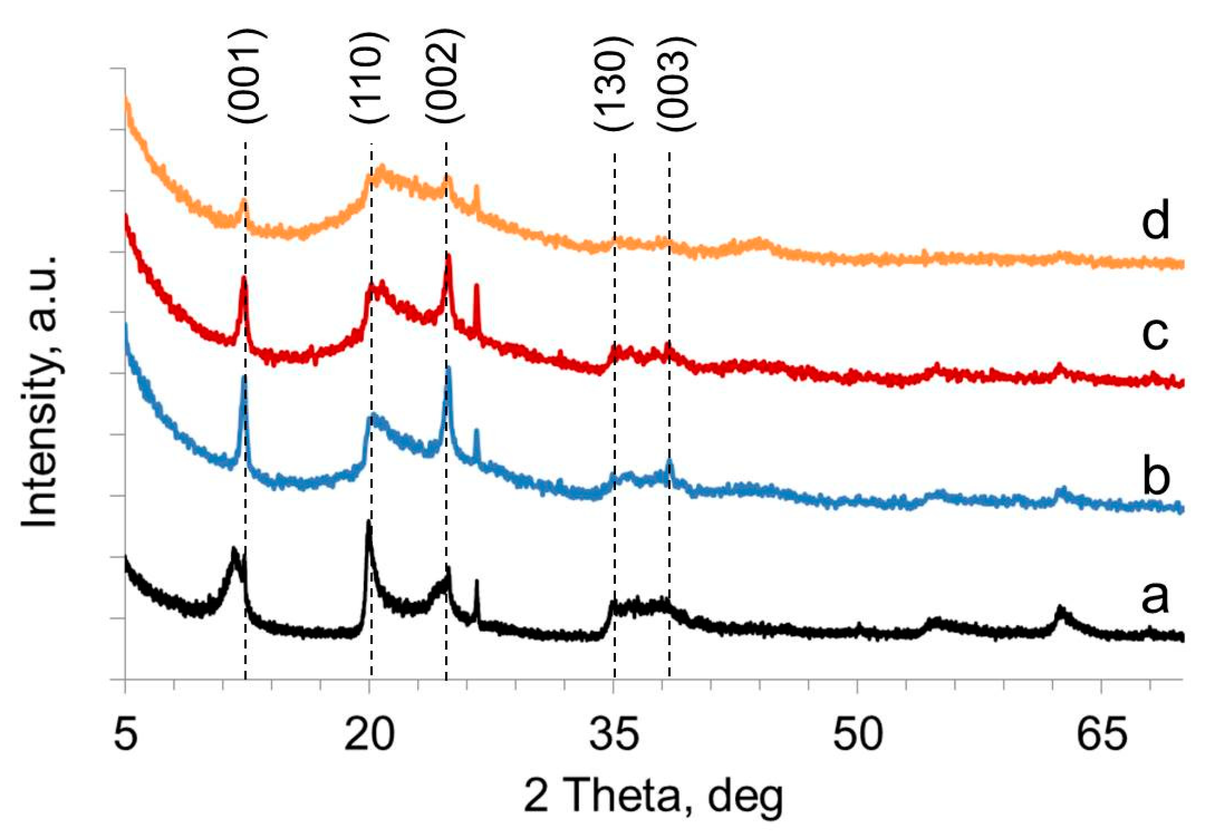
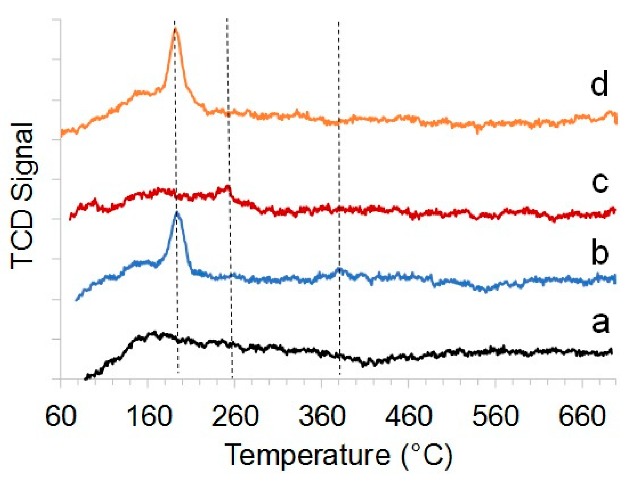
2.1. Structure, Morphology, and Composition of Ru-Loaded Halloysite Catalysts

Halloysite is based on rolled kaolin plates forming tubes of 50–60 nm outer diameter with a 12–15-nm-diameter inner lumen and a length of 500–800 nm. These nanotubes have different inside/outside chemistry composed of Al2O3 and SiO2, exhibiting different chemical reactivities. This allowed for selective tube lumen loading with metal ions [16].
Halloysite nanotubes with ruthenium nanoparticles inside were obtained using prior tubes loaded with various organic ligands with a further ruthenium salt solution socking inside the tube due to favorable metal–ligand complex formation and its reduction. To prevent nanoparticle formation on the outer surface, washing of excess of reagents was performed after each synthesis procedure. Ethylenediaminetetraacetic acid (EDTA) was chosen for HNT@Ru-1 preparation, urea was chosen for HNT@Ru-2, and acetone azine was chosen to obtain HNT@Ru-3. Organic molecules were intercalated inside nanotubes as described in the experimental section. To achieve a ruthenium concentration of ca. 2%, a two-step ruthenium chloride loading technique was modified from our previous work [17]. Before Fischer–Tropsch experiments, materials were reduced in a flow of H2 for 3 h at 400 °C.
The morphology of catalysts before and after Fischer–Tropsch reaction is shown in Figure 1 together with particle size distribution calculated from transmission electron microscopy (TEM) images. Selective ruthenium loading could be seen in all samples with a homogeneous nanoparticle distribution inside the aluminosilicate nanotubes. Particle size was similar, in the range of 1–8 nm with maxima between 2 and 4 nm and a particle size of 3.5 nm (Table 1). TEM of catalysts after Fischer–Tropsch synthesis showed no significant influence of reaction conditions on ruthenium particle distribution inside the nanotubes, as well as on their size. The stability of nanoparticles was reached due to their loading inside the tubes.
Si, Al, and Ru concentrations in pristine halloysite (HNT) and catalysts are shown in Table 1. It is known that the internal surface of halloysite is composed of alumina, while the external surface is composed of silica, whereby the concentration of Si and Al may be changed with acid or alkaline treatment [22]. To evaluate the chemical composition changes inside the nanotube, we used the Si/Al ratio calculated from elemental analysis data and observed changes; we obtained values of 0.93, 0.99, 0.93, and 0.96, respectively, for HNT, HNT@Ru-1, HNT@Ru-2, and HNT@Ru-3. We assumed that a small amount of Al was etched from samples HNT@Ru-1 and HNT@Ru-3. Ruthenium concentration was determined to be 2.0 wt.% for HNT@Ru-1 and HNT@Ru-2, and 2.2 wt.% for HNT@Ru-3 (Table 1).
X-ray diffractograms of pristine halloysite and halloysite nanotubes selectively loaded with ca. 2 wt.% of Ru are shown in Figure 2. The peak at 2θ = 12.36° is characteristic of dehydrated halloysite (d001 = 0.7 nm) [23,24]. The intensity of 12.36° (d001), 20.12° (d110), and 25.28° (d002) peaks decreased in the order HNT > HNT@Ru-1 ≥ HNT@Ru-2 > HNT@Ru-3. The halloysite-7Å was preserved in HNT@Ru-1 modified with ethylenediaminetetraacetic acid and urea-modified HNT@Ru-2. In the case of HNT@Ru-3 modified with acetone azine, the broadening of 12.35°, 20.12°, and 25.28° reflections belonging to the (001), (100), and (002) facets of halloysite revealed the amorphization of halloysite and formation of metahalloysite [25]. Generally, halloysite amorphization occurs during the dehydroxylation stage at 450 °C. In the case of modified halloysite, dehydroxylation partly occurred at 400 °C [26,27,28]. Ethylenediaminetetraacetic acid is too large to intercalate, and urea does not have a significant influence on dehydroxylation temperature. There are no prior studies on the influence of intercalated acetone azine on dehydroxylation temperature; we propose that it activated the interlayer hydroxyls and led to a decrease in the transition temperature. From Figure 1, it can be seen that, after thermal treatment and reaction, the clay tubular morphology was preserved. Due to the low concentration and small crystalline size of Ru nanoparticles (less than 5 nm), as well as the overlapping of signals, their presence was not confirmed by X-ray diffraction (XRD).
The specific surface areas of halloysite and HNT@Ru-1, HNT@Ru-2, and HNT@Ru-3 were determined using low-temperature nitrogen adsorption/desorption. The data obtained are summarized in Table 1 and varied in the range of 58 to 66 m2/g. Figure 3 shows that the samples had typical type IV isotherms of mesoporous materials [29,30]. The porous structure of halloysite was preserved after modification and deposition of ruthenium particles inside the lumen.
Analysis of the temperature-programmed desorption of ammonia (TPD) profiles was conducted. The thermal desorption curves of HNT@Ru-1 and HNT@Ru-3 had a major desorption area at 170–200 °C corresponding to weak acid sites (Figure 4). From TPD-NH3 curves, it can be seen that HNT@Ru-1 had an intensive peak at 190 °C and a tiny peak at 350 °C. HNT@Ru-2 had a very small peak at 260 °C corresponding to moderate acid sites. HNT@Ru-3 TPD-NH3 also showed the presence of mainly weak acid centers. The total number of acid sites in comparison with the pristine halloysite increased in the samples HNT@Ru-1 by 137 µmol/g NH3 and HNT@Ru-3 by 72 µmol/g NH3, whereas, for HNT @Ru-2, it decreased by 49 units (Table 1). Based on the obtained data (Table 1), we can conclude that the acidity decreased in the order HNT@Ru-1 > HNT@Ru-3 > HNT > HNT@Ru-2.

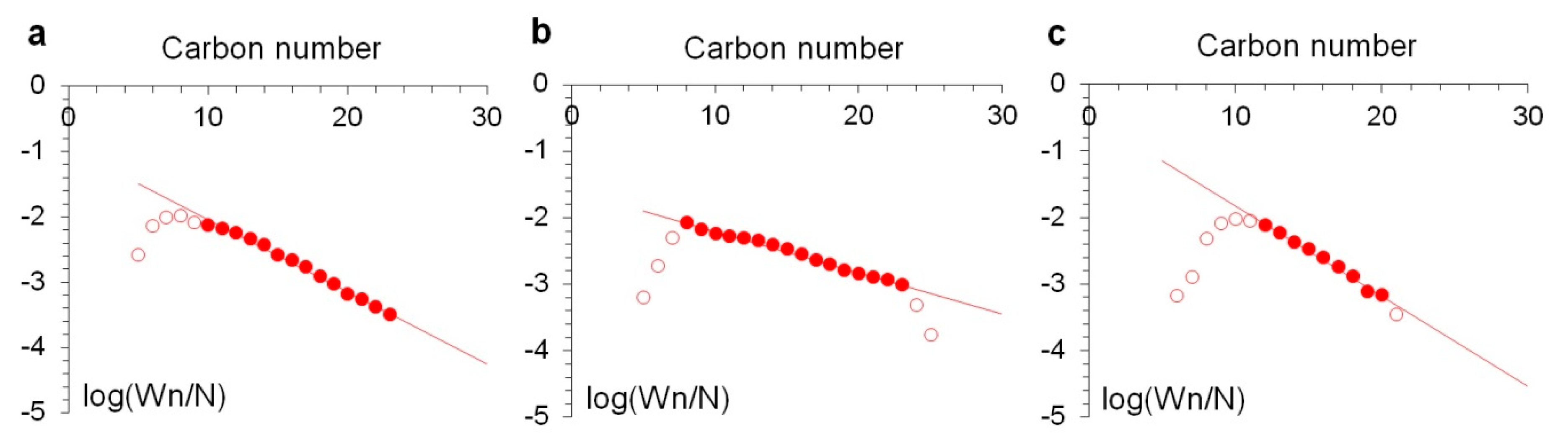
2.2. Catalytic Efficiency of Ru-Loaded Halloysite Catalysts in Fischer–Tropsch Synthesis

The Fischer–Tropsch synthesis was carried out in a fixed-bed flow-type reactor at 260 °C. After 32 h on stream, pseudo steady-state conditions were reached under which the concentrations of all products were determined. Catalyst performance was evaluated in terms of CO conversion and selectivity to particular products. Furthermore, ruthenium–time yield was calculated as amount of CO converted over one mole of Ru per second.
Carbon monoxide conversion slightly increased in the order HNT@Ru-1 < HNT@Ru-2 < HNT@Ru-3, although ruthenium–time yield values were very close for all three samples (Table 2). The conversion of CO on HNT@Ru-3 was slightly higher than for the other two catalysts. Considering that the actual Ru content in this catalyst was 10% higher than in the rest, the specific activity of ruthenium (Ru–time yield) was not the highest. Apparently, amorphization of the carrier in this catalyst does not affect activity. The synthesis products were only hydrocarbons, and the yield of oxygen-containing compounds was negligible. Notably, CO conversion into CO2 was at the limit of gas chromatography determination, indicating the very low activity of the catalysts in the water gas shift reaction.
Depending on the ligand being used for the catalyst preparation, CH4 selectivity varied widely from 19.9% to 52.8%. HNT@Ru-1 behaved as a methanation catalyst rather than FTS catalyst, accompanied by the highest total acidity values (Table 1). The highest selectivity to the most valuable C5+ hydrocarbons [30] was obtained over HNT@Ru-2, with the lowest methane and light-hydrocarbon selectivity. Yields of methane and light hydrocarbons obviously correlated with catalyst total acidity (Table 1). We attribute this to the acid-catalyzed secondary reactions of synthesized higher hydrocarbons, such as cracking and hydrogenolysis [31,32].
The molecular weight distribution of synthesized hydrocarbons obeyed the Anderson–Schulz–Flory (ASF) formula [33] (Figure 5). Some discrepancies with the ASF distribution in the field of low carbon numbers may be partly considered as an experimental artefact arising from the entrainment of light hydrocarbons with gas flow from the liquid product collector. Another probable reason was the readsorption of light olefins and their insertion into growing hydrocarbon chains, as well as the initiation of new chains [31,32]. Olefins are widely considered as primary FTS products [34,35,36]. The extremely low selectivity of HNT@Ru-2 and HNT@Ru-3 to C2–C4 hydrocarbons and the absence of olefins were indirect confirmations of the olefin reactions. The lowest percentage of olefins in C5+ products was obtained with HNT@Ru-2, which provided the highest ASF α value. We posit that the dense packing of Ru particles inside the halloysite lumen led to the re-adsorption of olefins, with subsequent hydrogenation and chain growth.
Thus, Ru-loaded halloysite catalysts provided considerable activity in CO hydrogenation, while their selectivity depended greatly on the preparation method. Urea-modified halloysite resulted in catalysts with high selectivity to valuable C5+ hydrocarbons, containing few olefins and a high number of heavy fractions.
For all tested catalysts, stationary conditions were achieved with no changes in CO conversion after 32 h on stream. The absence of changes in the dispersion of ruthenium in spent catalyst samples compared to the fresh ones confirmed that the catalysts were stable (Figure 1).

3. Materials and Methods

3.1. Materials

Aluminosilicate nanotubes (Al2Si2O5(OH)4) (Sigma-Aldrich, St. Louis, MO, USA), ethylenediaminetetraacetic acid (EDTA) (C10H16N2O8) (Sigma-Aldrich) ≥99.5%, urea ((NH2)2CO) (RusChem, Moscow, Russia), hydrazine hydrate solution (N2H4*H2O) 78%–82% (RusChem), ruthenium chloride (RuCl3) (Aurat, Moscow, Russia), and sodium borohydride powder (NaBH4) (RusChem) were used in this study.

3.2. Catalyst Preparation

Halloysite (1 g) and ethylenediaminetetraacetic acid (EDTA) (0.5 g) were dispersed in deionized water (30 mL) under ultrasound for 1 h. The resulting mixture was centrifuged (5500 rpm for 3 min) and washed three times with water to remove excess EDTA. The modified halloysite and ruthenium chloride (20 mg) were dispersed in ethanol (30 mL) for 30 min, and the dispersion was centrifuged (5500 rpm for 3 min). The precipitate was separated and washed with alcohol. Then, an aqueous solution of NaBH4 was added to reduce Ru3+. After completion of the reaction and degassing, the mixture was centrifuged and washed with water three times to remove by-products. The resulting precipitate was redispersed with ruthenium chloride (20 mg) in an alcohol medium, followed by washing and reduction of ruthenium complexes with NaBH4 to obtain metal in an amount of 2% by weight of halloysite. In the last step, the sample was dried at 65 °C for 24 h. As a result, HNT@Ru-1 was obtained.
To obtain HNT@Ru-2, the same procedure was performed; however, instead of ethylenediaminetetraacetic acid loading inside the tube, urea was used as a ligand. Halloysite (1 g) was dispersed in an aqueous solution of urea (30 mg/mL) under ultrasound for 1 h.
To obtain HNT@Ru-3, halloysite (1 g) was dispersed in hydrazine hydrate (20 mL) under ultrasound for 30 min. The resulting mixture was centrifuged (5500 rpm for 3 min), and the precipitate was separated and washed with ethanol three times to remove excess hydrazine hydrate. Then, acetone (20 mL) was gradually added to the precipitate and kept in an ultrasonic bath for 30 min. The reaction of acetone with hydrazine produced acetone azine. The reaction mixture was centrifuged and washed three times with acetone. Modified halloysite and ruthenium chloride (20 mg) were dispersed in acetone (30 mL) for 30 min to form ruthenium complexes inside aluminosilicate nanotubes. Then, the dispersion was centrifuged (5500 rpm for 3 min), and the precipitate was separated and washed with acetone. Next, an aqueous solution of NaBH4 was added to reduce Ru3+. After completion of the reaction and degassing, the mixture was centrifuged and washed with water three times to remove by-products. The resulting precipitate was redispersed with ruthenium chloride (20 mg) in acetone, followed by washing and reduction of ruthenium complexes with NaBH4. In the last step, the sample was dried at 35 °C for 24 h.
Prior to catalytic reaction, the catalysts were activated at normal pressure in a hydrogen flow at 400 °C for 4 h.

3.3. Catalyst Characterization

Textural characteristics of the samples obtained were determined on a Micromeritics Gemini VII 2390t instrument (Micromeritics Instrument Corp., Norcross, GA, USA) using the low-temperature N2-adsorption method. Before measurements, the samples were degassed at a temperature of 300 °C for 4 h. The specific surface area was calculated using the Brunauer–Emmett–Teller (BET) equation with adsorption data in the relative pressure range P/P0 = 0.05–0.35.
The acidity of the samples was evaluated using the temperature-programmed desorption of ammonia (NH3-TPD) technique on a Micromeritics AutoChem HP2950 instrument (Micromeritics Instrument Corp., Norcross, GA, USA). The sample weighed ~0.3 g; it was placed in a quartz reactor and kept in a nitrogen flow at 700 °C for 1 h with a rate of 50 mL·min–1. Saturation was carried out in a flow of dried ammonia diluted with nitrogen (8 vol.% NH3) at a temperature of 60 °C for 30 min. The removal of physically adsorbed ammonia was carried out at 100 °C in a nitrogen flow of 50 mL·min–1 for 30 min. To obtain the NH3-TPD curve, the temperature was gradually raised from 100 °C to 700 °C at a rate of 10 °C·min–1. Samples of fresh and spent catalysts were examined using a transmission electron microscope (JEM-2100, JEOL, Tokyo, Japan). The obtained images were processed using the Image J program developed by employees of the National Institutes of Health (Madison, WI, USA.) Particle size distribution was analyzed using 4–5 microphotographs based on counting 400–500 nanoparticles. The processed data were used to plot the histograms and determine the average particle size of the metal with Origin Software (8, Northampton, MA, USA).
Elemental analysis was performed on an ARL Quant’X energy-dispersive spectrometer (Thermo Fisher Scientific, Waltham, MS, USA) in air. The results were processed using the standard-less UniQuant method.
X-ray structural analysis (XRD) of the samples was carried out on a X-Ray Diffractometer (Rigaku SmartLab, Tokyo, Japan) in the 2θ range of 5°–80° at a speed of 5° per minute. Qualitative and quantitative analysis of the obtained diffraction patterns was carried out using the Rigaku PDXL software (Rigaku SmartLab, Tokyo, Japan) using the ICDD (International Center for Diffraction Data) and AMCSD (American Mineralogist Crystal Structure Database) databases.

3.4. Catalytic Experiment

The catalytic activity was studied in a Fischer–Tropsch laboratory synthesis fixed-bed unit with a stainless-steel flow integral reactor with an internal diameter of 14 mm. The catalyst (0.4 g) was mixed with 1 cm3 of quartz sand to avoid local overheating during hydrocarbon synthesis, and this mixture was loaded into the isothermal zone of the reactor. The activated catalysts were tested in the synthesis of hydrocarbons at a ratio of CO/H2 = 1/2, pressure = 1 MPa, and gas flow rate = 10 nL/(h × gcat). Temperature was gradually increased from 210 to 260 °C. After approximately 32 h at 260 °C, pseudo steady-state conditions were reached and catalytic performance (activity, selectivity) was evaluated.
Gas products (C1–C4 hydrocarbons, CO2) were analyzed with an LKM-80 gas chromatograph (1 m × 3 mm columns filled with molecular sieves, with helium as a carrier gas and a thermal conductivity detector, (LKM, Moscow, Russia)). C5+ liquid hydrocarbons were collected in a container at ambient temperature and analyzed with a Biochrome-1 instrument (quartz capillary column 50 m × 0.25 mm, with nitrogen as a carrier gas and a flame ionization detector, (LKM, Moscow, Russia)). The selectivity of C5+ was calculated using the difference in the total balance of mass and the quantity of gases C1–C4 and CO2.

4. Conclusions

For the first time, halloysite nanotubes selectively loaded with Ru nanoparticles via metal–organic complex reduction inside the lumen were used as catalysts for Fischer–Tropsch synthesis. A methanation catalyst with increased acidity compared to pristine nanotubes was produced when ethylenediaminetetraacetic acid was used for Ru complex formation inside nanotubes. The Ru nanocatalyst formed through urea assistant loading showed the highest selectivity to the most valuable C5+ hydrocarbons with α = 0.87. The highest olefin content in the C5+ fraction was reached with halloysite modified with acetone azine prior to ruthenium loading. No morphology changes were observed after 32 h on steam, confirming the stability of catalysts produced.

Author Contributions

Conceptualization, Y.L. and V.V.; methodology, A.S. and O.E.; investigation, K.M., P.G., A.G., M.K., and R.K.; data curation, A.S., A.G., and O.E.; writing—original draft preparation, A.S. and K.M.; writing—review and editing, O.E. and Y.L.; supervision, V.V. and Y.L.; project administration, P.G. and V.V. All authors have read and agreed to the published version of the manuscript.

Funding

This work was supported by the Ministry of Education and Science of the Russian Federation (Grant № 14.Z50.31.0035).

Conflicts of Interest

The authors declare no conflicts of interest.

References

  1. Zhang, S.; Yang, X.; Zhang, H.; Chu, C.; Zheng, K.; Ju, M.; Liu, L. Liquefaction of Biomass and Upgrading of Bio-Oil: A Review. Molecules 2019, 24, 2250. [Google Scholar] [CrossRef] [PubMed] [Green Version]
  2. Schulz, H. Short history and present trends of Fischer–Tropsch synthesis. Appl. Catal. A 1999, 186, 3–12. [Google Scholar] [CrossRef]
  3. Komaya, T.; Bell, A.T.; Wengsieh, Z.; Gronsky, R.; Engelke, F.; King, T.S.; Pruski, M. Effects of Dispersion and Metal-Metal Oxide Interactions on Fischer-Tropsch Synthesis over Ru/TiO2 and TiO2-Promoted Ru/SiO2. J. Catal. 1994, 150, 400–406. [Google Scholar] [CrossRef]
  4. Xiao, C.X.; Cai, Z.P.; Wang, T.; Kou, Y.; Yan, N. Aqueous-Phase Fischer–Tropsch Synthesis with a Ruthenium Nanocluster Catalyst. Angew. Chem. Int. Ed. 2008, 47, 746–749. [Google Scholar] [CrossRef] [PubMed]
  5. Iglesia, E.; Soled, S.L.; Fiato, R.A. Fischer-Tropsch synthesis on cobalt and ruthenium. Metal dispersion and support effects on reaction rate and selectivity. J. Catal. 1992, 137, 212–224. [Google Scholar] [CrossRef]
  6. Khadzhiev, S.N. Nanoheterogeneous catalysis: Definition, state, and research prospects. Petrol. Chem. 2016, 56, 465–479. [Google Scholar] [CrossRef]
  7. Buller, S.; Strunk, J. Nanostructure in energy conversion. J. Energy Chem. 2016, 25, 171–190. [Google Scholar] [CrossRef]
  8. Zaera, F. Shape-controlled nanostructures in heterogeneous catalysis. ChemSuschem 2013, 6, 1797–1820. [Google Scholar] [CrossRef]
  9. Dragutan, I.; Dragutan, V.; Demonceau, A. Special Issue on Ruthenium Complexes. Molecules 2017, 22, 255. [Google Scholar] [CrossRef] [Green Version]
  10. Cattaneo, S.; Naslhajian, H.; Somodi, F.; Evangelisti, C.; Villa, A.; Prati, L. Ruthenium on Carbonaceous Materials for the Selective Hydrogenation of HMF. Molecules 2018, 23, 2007. [Google Scholar] [CrossRef] [Green Version]
  11. Koh, T.; Koo, H.M.; Yu, T.; Lim, B.; Bae, J.W. Roles of Ruthenium–Support Interactions of Size-Controlled Ruthenium Nanoparticles for the Product Distribution of Fischer–Tropsch Synthesis. ACS Catal. 2014, 4, 1054–1060. [Google Scholar] [CrossRef]
  12. González-Carballo, J.M.; Finocchio, E.; García, S.; Rojas, S.; Ojeda, M.; Busca, G.; Fierro, J.L.G. Support effects on the structure and performance of ruthenium catalysts for the Fischer–Tropsch synthesis. Catal. Sci. Technol. 2011, 1, 1013–1023. [Google Scholar] [CrossRef]
  13. Phaahlamohlaka, T.N.; Kumia, D.O.; Dlamini, M.W.; Jewell, L.L.; Covillea, N.J. Ruthenium nanoparticles encapsulated inside porous hollow carbonspheres: A novel catalyst for Fischer–Tropsch synthesis. Catal. Today. 2016, 275, 76–83. [Google Scholar] [CrossRef]
  14. Tingjun, F.; Zhenhua, L. Review of recent development in Co-based catalysts supported on carbon materials for Fischer–Tropsch synthesis. Chem. Eng. Sci. 2015, 135, 3–20. [Google Scholar]
  15. Miners, S.A.; Rance, G.A.; Khlobystov, A.N. Chemical reactions confined within carbon nano-tubes. Chem. Soc. Rev. 2016, 45, 4727–4746. [Google Scholar] [CrossRef]
  16. Lvov, Y.; Abhishek, P.; Fu, Y.; Fakhrullin, R.; Kryuchkova, M.; Batasheva, S.; Stavitskaya, A.; Glotov, A.; Vinokurov, V. Interfacial Self-Assembly in Halloysite Nanotube Composites. Langmuir 2019, 35, 8646–8657. [Google Scholar] [CrossRef]
  17. Vinokurov, V.A.; Stavitskaya, A.V.; Chudakov, Y.A.; Glotov, A.P.; Ivanov, E.V.; Gushchin, P.A.; Lvov, Y.M.; Maximov, A.L.; Muradov, A.V.; Karakhanov, E.A. Core-shell nanoarchitecture: Schiff-base assisted synthesis of ruthenium in clay nanotubes. Pure Appl. Chem. 2018, 90, 825. [Google Scholar] [CrossRef]
  18. Vinokurov, V.A.; Stavitskaya, A.V.; Glotov, A.P.; Novikov, A.A.; Zolotukhina, A.V.; Kotelev, M.S.; Gushchin, P.A.; Ivanov, E.V.; Darrat, Y.; Lvov, Y.M. Nanoparticles Formed onto/into Halloysite Clay Tubules: Architectural Synthesis and Applications. Chem. Rec. 2018, 18, 858–867. [Google Scholar] [CrossRef]
  19. Glotov, A.P.; Stavitskaya, A.V.; Chudakov, Y.A.; Artemova, M.I.; Smirnova, E.M.; Demikhova, N.R.; Shabalina, T.N.; Gureev, A.A.; Vinokurov, V.A. Nanostructured Ruthenium Catalysts in Hydrogenation of Aromatic Compounds. Petrol. Chem. 2018, 58, 1221–1226. [Google Scholar] [CrossRef]
  20. Vinokurov, V.; Glotov, A.; Chudakov, Y.; Stavitskaya, A.; Ivanov, E.; Gushchin, P.; Zolotukhina, A.; Maximov, A.; Karakhanov, E.; Lvov, Y. Core/Shell Ruthenium–Halloysite Nanocatalysts for Hydrogenation of Phenol. Ind. Eng. Chem. Res. 2017, 56, 14043–14052. [Google Scholar] [CrossRef]
  21. Sufang, C.; Jinlin, L.; Yuhua, Z.; Daohong, Z.; Junjiang, Z. Effect of preparation method on halloysite supported cobalt catalysts for Fischer-Tropsch synthesis. J. Nat. Gas Chem. 2012, 21, 426–430. [Google Scholar]
  22. Gaaz, T.S.; Sulong, A.B.; Kadhum, A.A.H.; Nassir, M.H.; Al-Amiery, A.A. Impact of Sulfuric Acid Treatment of Halloysite on Physico-Chemical Property Modification. Materials 2016, 9, 620. [Google Scholar] [CrossRef] [PubMed]
  23. Szczepanik, B.; Słomkiewicz, P.; Garnuszek, M.; Czech, K.; Banaś, D.; Kubala-Kukuś, A.; Stabrawa, I. The effect of chemical modification on the physico-chemical characteristics of halloysite: Ftir, xrf, and xrd studies. J. Mol. Struct. 2015, 1084, 16–22. [Google Scholar] [CrossRef]
  24. Abdullayev, E.; Joshi, A.; Wei, W.B.; Zhao, Y.F.; Lvov, Y. Enlargement of halloysite clay nanotube lumen by selective etching of aluminum oxide. ACS Nano 2012, 6, 7216–7226. [Google Scholar] [CrossRef]
  25. Yuan, P.; Tan, D.; Annabi-Bergaya, F.; Yan, W.; Liu, D.; He, H. Changes in Structure, Morphology, Porosity, and Surface Activity of Mesoporous Halloysite Nanotubes Under Heating. Clays Clay Miner. 2012, 60, 561–573. [Google Scholar] [CrossRef]
  26. Mammadova, T.A.; Hasankhanova, N.V.; Teyubov, K.S.; Askerova, E.N.; Latifova, T.S.; Abbasov, V.M. Use of natural nanotubes of halloysite clay for thermochemical conversion of cottonseed oil. Catal. Sustain. Energy 2015, 2, 28–32. [Google Scholar] [CrossRef] [Green Version]
  27. Sahnoun, S.; Boutahala, M.; Hassina, Z.-B.; Zerroual, L. Trichlorophenol removal from aqueous solutions by modified halloysite: Kinetic and equilibrium studies. Desalin. Water Treat. 2015, 57, 1–11. [Google Scholar] [CrossRef]
  28. Ouyang, J.; Guo, B.; Fu, L.; Yang, H.; Hu, Y.; Tang, A.; Long, H.; Jin, Y.; Chen, J.; Jiang, J. Radical guided selective loading of silver nanoparticles at interior lumen and out surface of halloysite nanotubes. Mater. Des. 2016, 110, 169–178. [Google Scholar] [CrossRef]
  29. Barrientos-Ramírez, S.; Ramos-Fernández, E.V.; Silvestre-Albero, J.; Sepúlveda-Escribano, A.; Pastor-Blas, M.M.; González-Montiel, A. Use of nanotubes of natural halloysite as catalyst support in the atom transfer radical polymerization of methyl methacrylate. Micropor. Mesopor. Mater. 2009, 120, 132–140. [Google Scholar] [CrossRef]
  30. Eliseev, O.L.; Savost’yanov, A.P.; Sulima, S.I.; Lapidus, A.L. Recent development in heavy paraffins synthesis from CO and H2. Mendeleev Commun. 2018, 28, 345–351. [Google Scholar] [CrossRef]
  31. Novak, S.; Madon, R.J.; Suhl, H. Models of hydrocarbon product distributions in Fischer–Tropsch synthesis. J. Chem. Phys. 1981, 74, 6083–6091. [Google Scholar] [CrossRef]
  32. Novak, S.; Madon, R.J.; Suhl, H. Secondary effects in the Fischer-Tropsch synthesis. J. Catal. 1982, 77, 141–151. [Google Scholar] [CrossRef]
  33. Friedel, R.A.; Anderson, R.B. Composition of synthetic liquid fuels. I. Product distribution and analysis of C5-C8 paraffin isomers from cobalt catalyst. J. Am. Chem. Soc. 1950, 72, 1212–1215. [Google Scholar] [CrossRef]
  34. Erley, W.; McBreen, P.; Ibach, H. Evidence for CHx surface species after the hydrogenation of CO over an Fe(110) single crystal surface. J. Catal. 1983, 84, 229–234. [Google Scholar] [CrossRef]
  35. Wang, C.J.; Ekerdt, J.G. Evidence for alkyl intermediates during Fischer-Tropsch synthesis and their relation to hydrocarbon products. J. Catal. 1984, 86, 239–244. [Google Scholar] [CrossRef]
  36. Kaminsky, M.; Winograd, N.; Geoffroy, G.; Vannice, M.A. Direct SIMS observation of methylidyne, methylene, and methyl intermediates on a nickel (III) methanation catalyst. J. Am. Chem. Soc. 1986, 108, 1315–1316. [Google Scholar] [CrossRef]
Sample Availability: Samples of the compounds are available from the authors.
Figure 1. TEM image (A) and particle size distribution (B) of fresh pristine halloysite (HNT)@Ru-1 (a), HNT@Ru-2 (b), and HNT@Ru-3 (c) (left), and spent HNT@Ru-1 (a), HNT@Ru-2 (b), and HNT@Ru-3 (c) (right).
Molecules 25 01764 g001
Figure 2. X-ray diffraction (XRD) patterns for the HNT (a), HNT@Ru-1 (b), HNT@Ru-2 (c), and HNT@Ru-3 (d).
Molecules 25 01764 g002
Figure 3. N2 adsorption–desorption isotherms of HNT (a), HNT@Ru-1 (b), HNT@Ru-2 (c), and HNT@Ru-3 (d).
Molecules 25 01764 g003
Figure 4. NH3 temperature-programmed desorption (TPD) profiles of the HNT (a), HNT@Ru-1 (b), HNT@Ru-2 (c), and HNT@Ru-3 (d).
Molecules 25 01764 g004
Figure 5. Anderson–Schulz–Flory (ASF) plots of hydrocarbon formation over HNT@Ru-1 (a), HNT@Ru-2 (b), and HNT@Ru-3 (c).
Molecules 25 01764 g005
Table 1. Physico-chemical characteristics of Ru-loaded halloysite catalysts. BET—Brunauer–Emmett–Teller.
CatalystElemental Composition, wt. %Surface Area, BET, m2/gAverage Particles Size (TEM), nmTotal Acidity,
µmol/g
SiAlRu
HNT23.625.3-66None178
HNT@Ru-123.523.82.0633.5315
HNT@Ru-223.024.02.0603.5129
HNT@Ru-322.524.32.2583.5250
Table 2. Ru-loaded halloysite catalyst performance in Fischer–Tropsch synthesis 1.
ParameterHNT@Ru-1 HNT@Ru-2HNT@Ru-3
CO conversion, %15.617.818.8
Ru–time yield × 103, molCO/(molRu s)29.333.432.1
CH4 selectivity, %52.819.928.8
C2–C4 selectivity, %20.31.63.2
C5+ selectivity, %26.778.067.7
CO2 selectivity, %0.20.50.3
% olefins in C5+19.212.926.5
ASF α0.780.870.73
1 Reaction conditions: P = 1.0 MPa, T = 260 °C, H2/CO = 2:1, gas flow rate = 10 nL/(h gcat); data were collected after 32 h on steam. ASF—Anderson–Schulz–Flory.

