
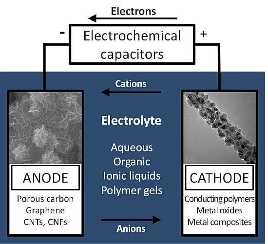
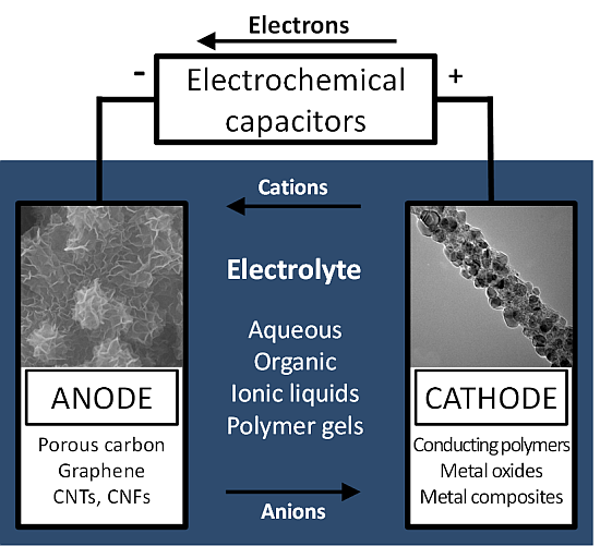
Nanostructured Electrode Materials for Electrochemical Capacitor Applications


Abstract
:
1. Introduction
2. EDLC Materials
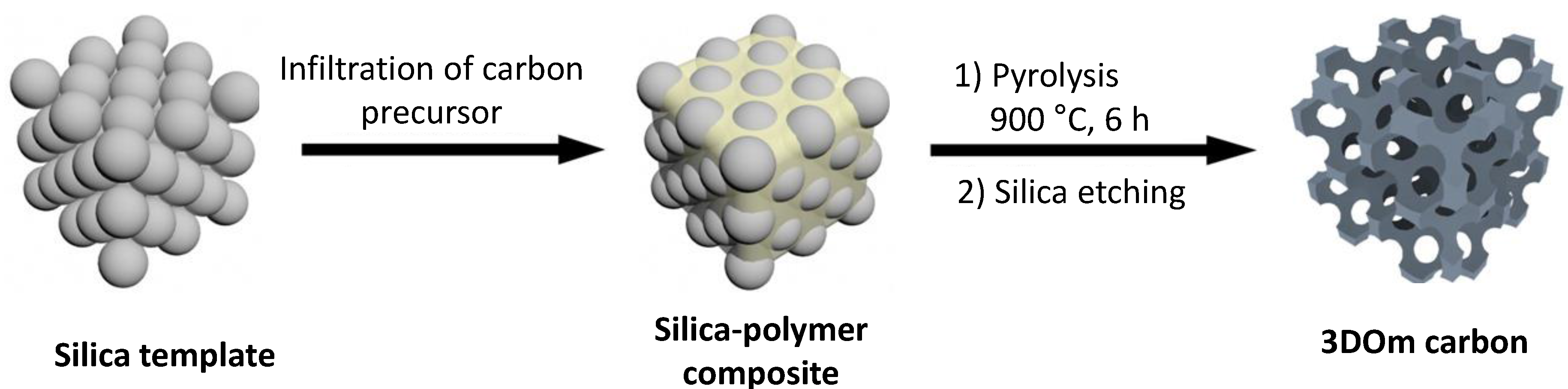
2.1. Porous Carbon


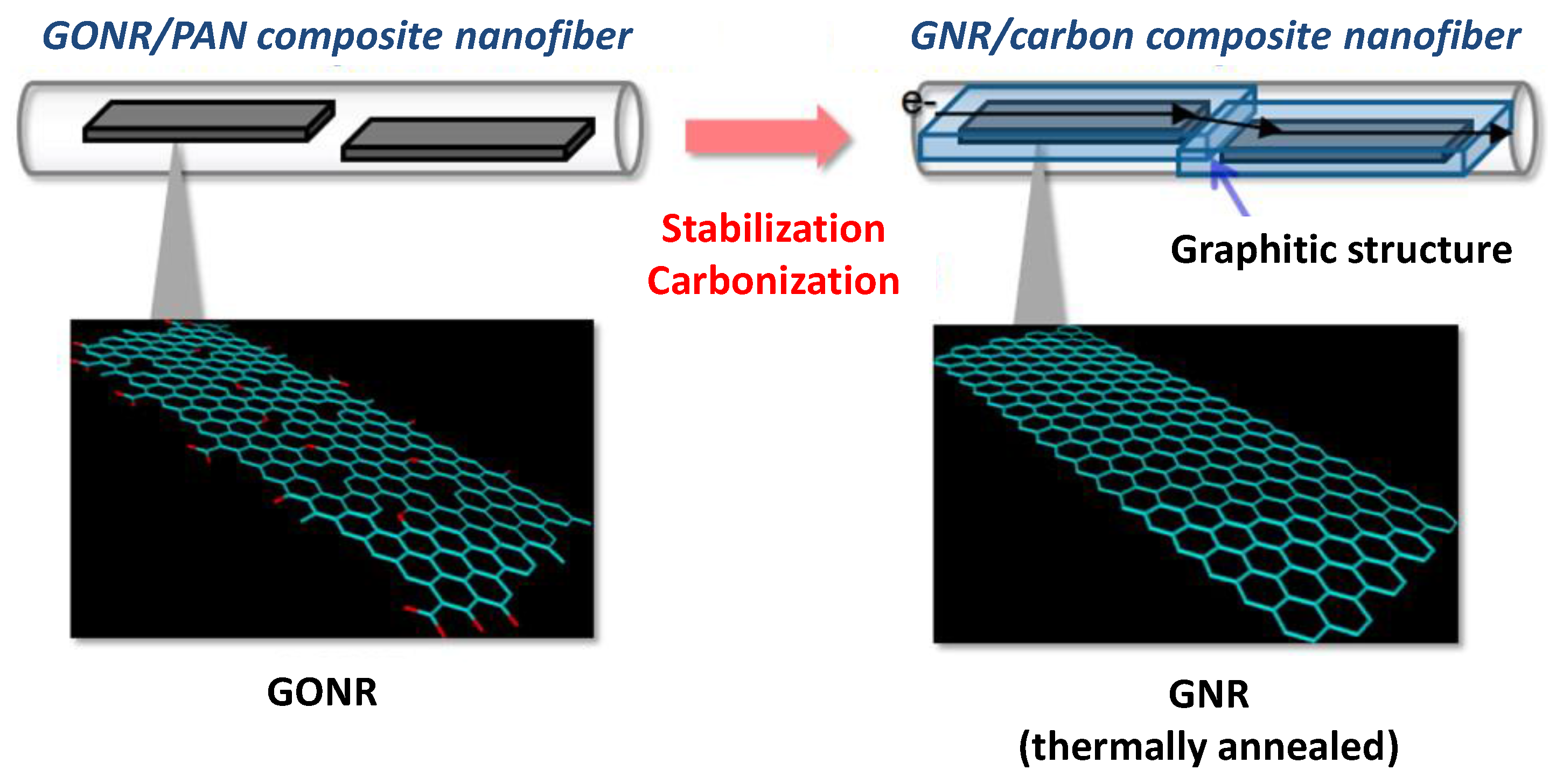
2.2. CNFs, CNTs, and Graphene


2.3. Summary

| Materials | Electrode System (1,2) | Electrolyte | Current Density or Scan Rate | Potential Range (V) | Specific Capacitance (F·g−1) | Ref. |
|---|---|---|---|---|---|---|
| Carbon nanosheets | Two | (3) EMIMBF4 | 1–10 A·g−1 | 3.5 | 155–242 | 6 |
| Carbon nanosheets | Two | PVA–H3PO4 gel | 0.25–1.3 A·g−1 | 0.8 | 4.9–29.2 | 7 |
| N-doped carbon nanosheets | Two | 1 M NaOH | 0.75–7 A·g−1 | 1.0 | 150–180 | 8 |
| Porous carbon nanowhiskers | Two | 6 M KOH | 0.5–30 A·g−1 | 1.0 | 125–210 | 16 |
| N-doped nanoporous carbon | Three | 6 M KOH | 0.5–40 A·g−1 | 1.0 | 90–240 | 17 |
| Nanofibers/mesoporous carbon | Three | 0.5 M K2SO4 | 0.5–6 A·g−1 | 0.8 | 72–99 | 18 |
| N-doped carbon nanospheres | Three | 6 M KOH | 0.5–40 A·g−1 | 1.0 | 62–194 | 19 |
| Nanoporous carbon | Two | (4) EMI–TFSI | 0.5–25 A·g−1 | 3.5 | 80–178 | 21 |
| N-doped nanoporous carbon | Three | 6 M KOH | 1–10 A·g−1 | 1.0 | 175–250 | 22 |
| Mesoporous carbon nanosheets | Two | (5) 1 M TEABF4/AN | 0.1–120 A·g−1 | 2.7 | 100–130 | 24 |
| GO-activate carbon | Two | EMIMBF4 | 1–10 A·g−1 | 3.5 | 110–135 | 25 |
| Porous carbon/CNTs | Two | 3 M H2SO4 | 0.1–50 A·g−1 | 0.9 | 125–237 | 26 |
| Porous CNFs | Two | EMI-TFSI | 5–100 mV·s−1 | 2.0 | 65–150 | 27 |
| Porous CNTs | Three | 1 M H2SO4 | 1–10 A·g−1 | 0.7 | 454–710 | 28 |
| Nanoporous carbon foams | Two | 6 M KOH | 0.2–20 A·g−1 | 1.1 | 125–379 | 29 |
| Carbonization of carbon hydrates | Two | 5 M KOH | 1 A·g−1 | 0.8 | 140 | 32 |
| Carbonized hollow nanocarbon | Two | 1 M KOH | 1–20 A·g−1 | 0.9 | 160–183 | 35 |
| Graphene-coated CNTs | Two | EMI-TFSI | 0.01–10 A·g−1 | 3.0 | 60–130 | 36 |
| Graphene/CNF | Three | 1 M H2SO4 | 0.2 A·g−1 | 1.5 | 174 | 39 |
| 3D porous graphene-like carbon | Two | (6) TEMABF4/PC | 1–32 A·g−1 | 2.5 | 156–178 | 40 |
| Mesoporous graphene nanoballs | Three | 1 M H2SO4 | 5–100 mV·s−1 | 0.8 | 206 | 41 |
| Graphene/CNT composite fibers | Two | 0.5 M H2SO4 | 0.2–2 A·g−1 | 0.8 | 6–35 | 42 |
| N-doped 3D nanoporous carbon | Two | 0.5 M Na2SO4 | 0.5–20 A·g−1 | 1.0 | 226–304 | 43 |
| Graphene/CNT | Two | EMIMBF4 | 10 A·g−11 | 4.0 | 199 | 44 |
| Graphene/carbon | Two | EMIMBF4 | 1–10 A·g−1 | 3.5 | 160–190 | 45 |
| RGO/CNT | Two | PVA–H2SO4 gel | 0.5–4 A·g−1 | 1.0 | 180–252 | 46 |
| Carbonized PPy nanostructures | Three | 1 M H2SO4 | 5 mV·s−1 | 0.9 | 264 | 47 |
| Carbonized PPy-CNTs | Three | 1 M KCL | 5–100 mV·s−1 | 1.5 | 40–140 | 48 |
| Halogen-containing nanoporous carbon | Three | 6 M KOH | 0.5–40 A·g−1 | 1.0 | 110–313 | 49 |
| Oxygen-rich nanoporous carbon | Two | 1 M H2SO4 | 0.5–10 A·g−1 | 1.0 | 210–297 | 50 |
3. Pseudocapacitive Materials
3.1. Conducting Polymers


3.2. Metal Oxides

3.3. Summary
| Materials | Electrode System (1,2) | Electrolyte | Current Density or Scan Rate | Potential Range (V) | Specific Capacitance (F·g−1) | Ref. |
|---|---|---|---|---|---|---|
| CoCl2 nanostructures | Three | 2 M KOH | 1 A·g−1 | 0.45 | 1962 | 9 |
| PANI nanotubes | Two | 1 M H2SO4 | 1–30 A·g−1 | 0.5 | 477–896 | 10 |
| PPy-clay core–shell nanoarrays | Three | 1 M KOH | 1–20 A·g−1 | 1.2 | 1750–2342 | 11 |
| Polythiophene nanostructures | Two | 0.5 M TEABF4 | 40–100 mV·s−1 | 4.0 | 75–250 | 12 |
| NiO nanoblocks | Three | 1 M KOH | 1.11–111 A·g−1 | 0.6 | 680–1336 | 51 |
| PPy–sepiolite nanocomposites | Three | 1 M KCl | 3 mA·cm−2 | 1.0 | 165 | 52 |
| ZnCo2O4 nanorods/Ni foams | Two | PVA-KOH gel | 1–20 A·g−1 | 1.0 | 1015–1400 | 53 |
| NiCo2(OH)6 nanotubes | Two | 1.9 M KCL 0.1M KOH | 10–100 A·g−1 | 0.5 | 169–200 | 54 |
| 3D Co3O4 nanonetworks | Three | 6 M KOH | 2–100 mV·s−1 | 1.5 | 546–1049 | 55 |
| Ni2(CO3)(OH)2 nanosheets | Three | 3 M KOH | 0.5–10 A·g−1 | 0.4 | 612–1178 | 56 |
| PPy–PANI double-wall nanotubes | Three | 1 M H2SO4 | 5–250 mV·s−1 | 0.6 | 366–693 | 58 |
| PANI nanofibers | Three | 1 M H2SO4 | 0.1–10 A·g−1 | 0.8 | 20–192 | 61 |
| PPy nanofibrils | Three | 1 M H2SO4 | 0.1 A·g−1 | 0.7 | 280 | 62 |
| Hollow NiCo2S4 nanoplates | Three | 3 M KOH | 1–20 A·g−1 | 0.5 | 231–437 | 63 |
| α-Fe2O3/MnO2 nanowires | Three | 0.7 M H3BO3 | 1–50 A·g−1 | 0.6 | 480–838 | 70 |
| 2D TiS2 nanocrystals | Three | 1 M LiClO4 | 0.5–10 A·g−1 | 1.2 | 320–470 | 71 |
| CoAl/PEDOT nanoarrays | Three | 6 M KOH | 1–40 A·g−1 | 0.6 | 424–672 | 76 |
| Au-MnO2 core–shell nanomesh | Two | PVA-LiClO4 gel | 0.56 A·g−1 | 2.0 | 524 | 77 |
| CoO/PPy nanowires | Two | 3 M NaOH | 1–50 mA·cm−2 | 1.6 | 647–2223 | 78 |
| V2O5-PPy nanofibers | Two | PVA-LiCl gel | 4.5 mA·cm−2 | 2.0 | 412 | 79 |
| CuO nanowires | Three | 2 M KOH | 1–5 A·g−1 | 0.45 | 102–118 | 80 |
| Nanoporous Ni(OH)2 films | Two | 6 M KOH | 0.9–50 A·g−1 | 1.6 | 20–192 | 81 |
| β-Co(OH)2 nanosheets | Two | 2 M KOH | 1–25 A·g−1 | 0.5 | 1530–2080 | 82 |
| Co3O4 nanostructures | Two | 2 M KOH | 0.5–2.5 A·g−1 | 0.8 | 150–476 | 83 |
| NiCo2O4 nanosheets | Three | 2 M KOH | 6–30 A·g−1 | 0.5 | 1500–1886 | 84 |
4. Hybrid Capacitive Materials
4.1. Coupling EDLC and Pseudocapacitive Materials

4.2. Asymmetric Hybrid Capacitors


4.3. 3D Nanostructured Graphene-Based Capacitors


4.4. Summary
| Materials (1) | Electrode System (2,3) | Electrolyte | Current Density or Scan Rate | Potential Range (V) | Specific capacitance (F·g−1) | Ref. |
|---|---|---|---|---|---|---|
| NiO/graphene | Two | 1 M NaOH | 7–20 A·g−1 | 1.5 | 130–440 | 13 |
| Porous carbon/ Fe2O3 nanoparticles | Three | 1 M Na2SO3 | 0.5–10 A·g−1 | 1.0 | 119–235 | 14 |
| α-Fe2O3/Graphene | Three | 1 M Na2SO4 | 3–10 A·g−1 | 1.0 | 98–306 | 15 |
| Ni graphene aerogels | Two | 6 M KOH | 2–20 A·g−1 | 1.0 | 186–366 | 85 |
| CoO carbon nanoflakes | Three | 2 M KOH | 10 mA·cm−2 | 0.75 | 476 | 86 |
| Faradaic CNTs | Three | 0.5 M H2SO4 | 3–100 mV·s−1 | 0.9 | 75–260 | 87 |
| Nanoporous CuO/active carbon | Two | 3 M KOH | 1–10 A·g−1 | 1.4 | 54–72 | 88 |
| Co(OH)2/graphene | Three | 6 M KOH | 2–10 A·g−1 | 0.7 | 356–532 | 89 |
| PANI/RGO | Three | 1 M H2SO4 | 0.45 A·g−1 | 0.8 | 431 | 90 |
| PANI/CNF | Three | 1 M H2SO4 | 0.3–10 A·g−1 | 1.2 | 400–557 | 91 |
| PANI/N-doped CNTs | Three | 0.1 M Na2SO4 | 50 mV·s−1 | 1.0 | 250 | 92 |
| PPy/graphene | Two | 1 M H2SO4 | 0.1 A·g−1 | 1.0 | 277 | 94 |
| Ni–Mn–RGO | Two | 1 M KOH | 2–10 A·g−1 | 1.6 | 724–1985 | 95 |
| 3D carbon/CoNi3O4 asymmetric | Two | 3 M KOH | 1–100 mA·cm−2 | 1.8 | 42–64 | 96 |
| N-doped carbon/PANI asymmetric | Two | 1 M Na2SO4 | 0.5–20 A·g−1 | 1.1 | 75–113 | 97 |
| WO3/PPy nanowire asymmetric | Three | 3 M NaOH | 0.7–7 mA·cm−2 | 0.6 | 250–800 | 98 |
| Mn–Ni–Co oxide nanowire/RGO asymmetric | Three | 6 M KOH | 1–20 A·g−1 | 0.5 | 404–638 | 99 |
| PEDOT/ROG/CNF asymmetric | Two | 1 M H2SO4 | 0.1–2 A·g−1 | 1.0 | 50–60 | 100 |
| MnO2/GO asymmetric | Two | 1 M Na2SO4 | 0.1–2 A·g−1 | 2.0 | 41–84 | 101 |
| RGO/MnO2 asymmetric | Three | 1 M Na2SO4 | 0.1–1 A·g−1 | 1.5 | 217–243 | 102 |
| CNF/GO/PANI | Two | 1 M H2SO4 | 2 A·g−1 | 0.8 | 479 | 103 |
| Ni/graphene/CNT | Two | 6 M KOH | 0.2–1.0 A·g−1 | 0.8 | 100–105 | 104 |
| Graphene/PANI nanorods | Three | 1 M H2SO4 | 1–8 A·g−1 | 0.7 | 836–1665 | 106 |
| 3D CoMoO4/graphene | Three | 2 M KOH | 1.5–85 A·g−1 | 0.9 | 1101–2741 | 108 |
| Graphene/CNT/Mn | Two | 2 M Li2SO4 | 1.9 A·g−1 | 1.6 | 1108 | 109 |
| PPy nanowire/RGO | Two | PVA–H2SO4 gel | 1–20 A·g−1 | 0.8 | 361–434 | 110 |
| Porous graphene/PANI | Two | 1 M H2SO4 | 1–8 A·g−1 | 0.8 | 458–864 | 111 |
| Porous graphene/PANI | Two | 1 M H2SO4 | 0.5–10 A·g−1 | 0.7 | 362–385 | 112 |
5. Outlook


- (i)
- control of the 3D structure of electrode materials in the nanometer regime,
- (ii)
- battery-like hybrid capacitors with both high energy and power densities,
- (iii)
- flexible, all-solid-state devices,
- (iv)
- use of intrinsically conductive binders or no binder,
- (v)
- increased volumetric capacitance.
Acknowledgments
Conflicts of Interest
References
- Faraji, S.; Ani, F.N. The development supercapacitor from activated carbon by electroless plating—A review. Renew. Sustain. Energy Rev. 2015, 42, 823–834. [Google Scholar]
- Pandolfo, T.; Ruiz, V.; Sivakkumar, S.; Nerkar, J. Supercapacitors: Materials, Systems, and Applications; Wiley-VCH Verlag GmbH & Co. KgaA: Weinheim, Germany, 2013; pp. 69–109. [Google Scholar]
- Chen, Z.; Yu, D.; Xiong, W.; Liu, P.; Liu, Y.; Dai, L. Graphene-based nanowire supercapacitors. Langmuir 2014, 30, 3567–3571. [Google Scholar] [CrossRef] [PubMed]
- Simon, P.; Taberna, P.-L.; Béguin, F. Supercapacitors: Materials, Systems, and Applications; Wiley-VCH Verlag GmbH & Co. KgaA: Weinheim, Germany, 2013; pp. 131–165. [Google Scholar]
- Wang, G.; Zhang, L.; Zhang, J. A review of electrode materials for electrochemical supercapacitors. Chem. Soc. Rev. 2012, 41, 797–828. [Google Scholar] [CrossRef] [PubMed]
- Hou, J.; Cao, C.; Idrees, F.; Ma, X. Hierarchical porous nitrogen-doped carbon nanosheets derived from silk for ultrahigh-capacity battery anodes and supercapacitors. ACS Nano 2015, 9, 2556–2564. [Google Scholar] [CrossRef] [PubMed]
- Chen, T.; Peng, H.; Durstock, M.; Dai, L. High-performance transparent and stretchable all-solid supercapacitors based on highly aligned carbon nanotube sheets. Sci. Rep. 2014, 4, 3612. [Google Scholar] [CrossRef] [PubMed]
- Li, Y.; Dong, J.; Zhang, J.; Zhao, X.; Yu, P.; Jin, L.; Zhang, Q. Nitrogen-doped carbon membrane derived from polyimide as free-standing electrodes for flexible supercapacitors. Small 2015, 11. [Google Scholar] [CrossRef] [PubMed]
- Chen, K.; Yang, Y.; Li, K.; Ma, Z.; Zhou, Y.; Xue, D. CoCl2 designed as excellent pseudocapacitor electrode materials. ACS Sustain. Chem. Eng. 2014, 2, 440–444. [Google Scholar] [CrossRef]
- Chen, W.; Rakhi, R.B.; Alshareef, H.N. Morphology-dependent enhancement of the pseudocapacitance of template-guided tunable polyaniline nanostructures. J. Phys. Chem. C 2013, 117, 15009–15019. [Google Scholar] [CrossRef]
- Shao, M.; Li, Z.; Zhang, R.; Ning, F.; Wei, M.; Evans, D.G.; Duan, X. Hierarchical conducting polymer@clay core–shell arrays for flexible all-solid-state supercapacitor devices. Small 2015. [Google Scholar] [CrossRef] [PubMed]
- Nejati, S.; Minford, T.E.; Smolin, Y.Y.; Lau, K.K.S. Enhanced charge storage of ultrathin polythiophene films within porous nanostructures. ACS Nano 2014, 8, 5413–5422. [Google Scholar] [CrossRef] [PubMed]
- Terasawa, N.; Asaka, K. High-performance hybrid (electrostatic double-layer and faradaic capacitor-based) polymer actuators incorporating nickel oxide and vapor-grown carbon nanofibers. Langmuir 2014, 30, 14343–14351. [Google Scholar] [CrossRef] [PubMed]
- Lin, Y.; Wang, X.; Qian, G.; Watkins, J.J. Additive-driven self-assembly of well-ordered mesoporous carbon/iron oxide nanoparticle composites for supercapacitors. Chem. Mater. 2014, 26, 2128–2137. [Google Scholar] [CrossRef]
- Yang, S.; Song, X.; Zhang, P.; Sun, J.; Gao, L. Self-assembled α-Fe2O3 mesocrystals/graphene nanohybrid for enhanced electrochemical capacitors. Small 2014, 10, 2270–2279. [Google Scholar] [CrossRef] [PubMed]
- Zhang, J.; Zhang, X.; Zhou, Y.; Guo, S.; Wang, K.; Liang, Z.; Xu, Q. Nitrogen-doped hierarchical porous carbon nanowhisker ensembles on carbon nanofiber for high-performance supercapacitors. ACS Sustain. Chem. Eng. 2014, 2, 1525–1533. [Google Scholar] [CrossRef]
- Chen, X.Y.; Chen, C.; Zhang, Z.J.; Xie, D.H.; Deng, X. Nitrogen-doped porous carbon prepared from urea formaldehyde resins by template carbonization method for supercapacitors. Ind. Eng. Chem. Res. 2013, 52, 10181–10188. [Google Scholar] [CrossRef]
- Liu, W.J.; Tian, K.; He, Y.-R.; Jiang, H.; Yu, H.Q. High-yield harvest of nanofibers/mesoporous carbon composite by pyrolysis of waste biomass and its application for high durability electrochemical energy storage. Environ. Sci. Technol. 2014, 48, 13951–13959. [Google Scholar] [CrossRef] [PubMed]
- Chen, X.Y.; Chen, C.; Zhang, Z.J.; Xie, D.H. Nitrogen-doped porous carbon spheres derived from polyacrylamide. Ind. Eng. Chem. Res. 2013, 52, 12025–12031. [Google Scholar] [CrossRef]
- Chen, J.; Li, C.; Shi, G. Graphene materials for electrochemical capacitors. J. Phys. Chem. Lett. 2013, 4, 1244–1253. [Google Scholar] [CrossRef]
- Vu, A.; Li, X.; Phillips, J.; Han, A.; Smyrl, W.H.; Bühlmann, P.; Stein, A. Three-dimensionally ordered mesoporous (3DOm) carbon materials as electrodes for electrochemical double-layer capacitors with ionic liquid electrolytes. Chem. Mater. 2013, 25, 4137–4148. [Google Scholar] [CrossRef]
- Cho, K.T.; Lee, S.B.; Lee, J.W. Facile synthesis of highly electrocapacitive nitrogen-doped graphitic porous carbons. J. Phys. Chem. C 2014, 118, 9357–9367. [Google Scholar] [CrossRef]
- Fedorov, M.V.; Kornyshev, A.A. Ionic liquids at electrified interfaces. Chem. Rev. 2014, 114, 2978–3036. [Google Scholar] [CrossRef] [PubMed] [Green Version]
- Fuertes, A.B.; Sevilla, M. Hierarchical microporous/mesoporous carbon nanosheets for high-performance supercapacitors. ACS Appl. Mater. Interfaces 2015, 7, 4344–4353. [Google Scholar] [CrossRef] [PubMed]
- Yang, X.; Zhang, F.; Zhang, L.; Zhang, T.; Huang, Y.; Chen, Y. A High-performance graphene oxide-doped ion gel as gel polymer electrolyte for all-solid-state supercapacitor applications. Adv. Funct. Mater. 2013, 23, 3353–3360. [Google Scholar] [CrossRef]
- Yao, Y.; Ma, C.; Wang, J.; Qiao, W.; Ling, L.; Long, D. Rational design of high-surface-area carbon nanotube/microporous carbon core–shell nanocomposites for supercapacitor electrodes. ACS Appl. Mater. Interfaces 2015, 7, 4817–4825. [Google Scholar] [CrossRef] [PubMed]
- Richey, F.W.; Tran, C.; Kalra, V.; Elabd, Y.A. Ionic liquid dynamics in nanoporous carbon nanofibers in supercapacitors measured with in operando infrared spectroelectrochemistry. J. Phys. Chem. C 2014, 118, 21846–21855. [Google Scholar] [CrossRef]
- Chen, X.; Wang, H.; Yi, H.; Wang, X.; Yan, X.; Guo, Z. Anthraquinone on porous carbon nanotubes with improved supercapacitor performance. J. Phys. Chem. C 2014, 118, 8262–8270. [Google Scholar] [CrossRef]
- You, B.; Jiang, J.; Fan, S. Three-dimensional hierarchically porous all-carbon foams for supercapacitor. ACS Appl. Mater. Interfaces 2014, 6, 15302–15308. [Google Scholar] [CrossRef] [PubMed]
- Qin, Z.; Taylor, M.; Hwang, M.; Bertoldi, K.; Buehler, M.J. Effect of wrinkles on the surface area of graphene: Toward the design of nanoelectronics. Nano Lett. 2014, 14, 6520–6525. [Google Scholar] [CrossRef] [PubMed]
- Chen, X.; Qiu, L.; Ren, J.; Guan, G.; Lin, H.; Zhang, Z.; Chen, P.; Wang, Y.; Peng, H. Novel electric double-layer capacitor with a coaxial fiber structure. Adv. Mater. 2013, 25, 6436–6441. [Google Scholar] [CrossRef] [PubMed]
- Krishnan, D.; Raidongia, K.; Shao, J.; Huang, J. Graphene oxide assisted hydrothermal carbonization of carbon hydrates. ACS Nano 2014, 8, 449–457. [Google Scholar] [CrossRef] [PubMed]
- Matsumoto, H.; Imaizumi, S.; Konosu, Y.; Ashizawa, M.; Minagawa, M.; Tanioka, A.; Lu, W.; Tour, J.M. Electrospun composite nanofiber yarns containing oriented graphene nanoribbons. ACS Appl. Mater. Interfaces 2013, 5, 6225–6231. [Google Scholar] [CrossRef] [PubMed]
- Deng, L.; Young, R.J.; Kinloch, J.A.; Abdelkader, A.M.; Holmes, S.M.; Rio, D.A.; Eichhorn, S.J. Supercapacitance from cellulose and carbon nanotube nanocomposite fibers. ACS Appl. Mater. Interfaces 2013, 5, 9983–9990. [Google Scholar] [CrossRef] [PubMed]
- Zhang, J.; Wang, K.; Guo, S.; Wang, S.; Liang, Z.; Chen, Z.; Fu, J.; Xu, Q. One-step carbonization synthesis of hollow carbon nanococoons with multimodal pores and their enhanced electrochemical performance for supercapacitors. ACS Appl. Mater. Interfaces 2014, 6, 2192–2198. [Google Scholar] [CrossRef] [PubMed]
- Wilson, E.; Islam, M.F. Ultracompressible, high-rate supercapacitors from graphene-coated carbon nanotube aerogels. ACS Appl. Mater. Interfaces 2015, 7, 5612–5618. [Google Scholar] [CrossRef] [PubMed]
- Stoner, B.R.; Raut, A.S.; Brown, B.; Parker, C.B.; Glass, J.T. Graphenated carbon nanotubes for enhanced electrochemical double layer capacitor performance. Appl. Phys. Lett. 2011, 99, 183104. [Google Scholar] [CrossRef]
- Yu, K.; Lu, G.; Bo, Z.; Mao, S.; Chen, J. Carbon nanotube with chemically bonded graphene leaves for electronic and optoelectronic applications. J. Phys. Chem. Lett. 2011, 2, 1556–1562. [Google Scholar] [CrossRef]
- Kwon, O.S.; Kim, T.; Lee, J.S.; Park, S.J.; Park, H.-W.; Kang, M.; Lee, J.E.; Jang, J.; Yoon, H. Fabrication of graphene sheets intercalated with manganese oxide/carbon nanofibers: Toward high-capacity energy storage. Small 2013, 9, 248–254. [Google Scholar] [CrossRef] [PubMed]
- Li, Y.; Li, Z.; Shen, P.K. Simultaneous formation of ultrahigh surface area and three-dimensional hierarchical porous graphene-like networks for fast and highly stable supercapacitors. Adv. Mater. 2013, 25, 2474–2480. [Google Scholar] [CrossRef] [PubMed]
- Lee, J.-S.; Kim, S.-I.; Yoon, J.-C.; Jang, J.-H. Chemical vapor deposition of mesoporous graphene nanoballs for supercapacitor. ACS Nano 2013, 7, 6047–6055. [Google Scholar] [CrossRef] [PubMed]
- Sun, H.; You, X.; Deng, J.; Chen, X.; Yang, Z.; Ren, J.; Peng, H. Novel graphene/carbon nanotube composite fibers for efficient wire-shaped miniature energy devices. Adv. Mater. 2014, 26, 2868–2873. [Google Scholar]
- Peng, H.; Ma, G.; Sun, K.; Mu, J.; Zhang, Z.; Lei, Z. Facile synthesis of poly(p-phenylenediamine)-derived three-dimensional porous nitrogen-doped carbon networks for high performance supercapacitors. J. Phys. Chem. C 2014, 118, 29507–29516. [Google Scholar] [CrossRef]
- Pham, D.T.; Lee, T.H.; Luong, D.H.; Yao, F.; Ghosh, A.; Le, V.T.; Kim, T.H.; Li, B.; Chang, J.; Lee, Y.H. Carbon nanotube-bridged graphene 3D building blocks for ultrafast compact supercapacitors. ACS Nano 2015, 9, 2018–2027. [Google Scholar] [CrossRef] [PubMed]
- Yang, X.; Zhang, L.; Zhang, F.; Zhang, T.; Huang, Y.; Chen, Y. A high-performance all-solid-state supercapacitor with graphene-doped carbon material electrodes and a graphene oxide-doped ion gel electrolyte. Carbon 2014, 72, 381–386. [Google Scholar] [CrossRef]
- Zheng, Q.; Cai, Z.; Ma, Z.; Gong, S. Cellulose nanofibril/reduced graphene oxide/carbon nanotube hybrid aerogels for highly flexible and all-solid-state supercapacitors. ACS Appl. Mater. Interfaces 2015, 7, 3263–3271. [Google Scholar] [CrossRef] [PubMed]
- Huang, X.; Kim, S.; Heo, M.S.; Kim, J.E.; Suh, H.; Kim, I. Easy synthesis of hierarchical carbon spheres with superior capacitive performance in supercapacitors. Langmuir 2013, 29, 12266–12274. [Google Scholar] [CrossRef] [PubMed]
- Ćirić-Marjanović, C.; Mentus, S.; Pašti, I.; Gavrilov, N.; Krstić, J.; Travas-Sejdic, J.; Strover, L.T.; Kopecká, J.; Moravková, Z.; Trchová, M.; et al. Synthesis, characterization, and electrochemistry of nanotubular polypyrrole and polypyrrole-derived carbon nanotubes. J. Phys. Chem. C 2014, 118, 14770–14784. [Google Scholar]
- Chen, X.Y.; Cheng, L.X.; Deng, X.; Zhang, L.; Zhang, Z.J. Generalized conversion of halogen-containing plastic waste into nanoporous carbon by a template carbonization method. Ind. Eng. Chem. Res. 2014, 53, 6990–6997. [Google Scholar] [CrossRef]
- Zhao, Y.; Ran, W.; He, J.; Song, Y.; Zhang, C.; Xiong, D.-B.; Gao, F.; Wu, J.; Xia, Y. Oxygen-rich hierarchical porous carbon derived from artemia cyst Shells with superior electrochemical performance. ACS Appl. Mater. Interfaces 2015, 7, 1132–1139. [Google Scholar] [CrossRef] [PubMed]
- Singh, A.K.; Sarkar, D.; Khan, G.G.; Mandal, K. Hydrogenated NiO nanoblock architecture for high performance pseudocapacitor. ACS Appl. Mater. Interfaces 2014, 6, 4684–4692. [Google Scholar] [CrossRef] [PubMed]
- Chang, Y.; Liu, Z.; Fu, Z.; Wang, C.; Dai, Y.; Peng, R.; Hu, X. Preparation and characterization of one-dimensional core–shell sepiolite/polypyrrole nanocomposites and effect of organic modification on the electrochemical properties. Ind. Eng. Chem. Res. 2014, 53, 38–47. [Google Scholar] [CrossRef]
- Liu, B.; Liu, B.; Wang, Q.; Wang, X.; Xiang, Q.; Chen, D.; Shen, G. New energy storage option: Toward ZnCo2O4 nanorods/nickel foam architectures for high-performance supercapacitors. ACS Appl. Mater. Interfaces 2013, 5, 10011–10017. [Google Scholar] [CrossRef] [PubMed]
- Shang, C.; Dong, S.; Wang, S.; Xiao, D.; Han, P.; Wang, X.; Gu, L.; Cui, G. Coaxial NixCo2x(OH)6x/TiN nanotube arrays as supercapacitor electrodes. ACS Nano 2013, 7, 5430–5436. [Google Scholar] [CrossRef] [PubMed]
- Zhang, J.; Fu, J.; Zhang, J.; Ma, H.; He, Y.; Li, F.; Xie, E.; Xue, D.; Zhang, H.; Peng, Y. Co@Co3O4 core–shell three-dimensional nano-network for high-performance electrochemical energy storage. Small 2014, 10, 2618–2624. [Google Scholar] [CrossRef] [PubMed]
- Zhu, G.; Xi, C.; Shen, M.; Bao, C.; Zhu, J. Nanosheet-based hierarchical Ni2(CO3)(OH)2 microspheres with weak crystallinity for high-performance supercapacitor. ACS Appl. Mater. Interfaces 2014, 6, 17208–17214. [Google Scholar] [CrossRef] [PubMed]
- Yoon, H.; Choi, M.; Lee, K.J.; Jang, J. Versatile strategies for fabricating polymer nanomaterials with controlled size and morphology. Macromol. Res. 2008, 16, 85–102. [Google Scholar] [CrossRef]
- Wang, Z.-L.; He, X.-J.; Ye, S.-H.; Tong, Y.-X.; Li, G.-R. Design of polypyrrole/polyaniline double-walled nanotube arrays for electrochemical energy storage. ACS Appl. Mater. Interfaces 2014, 6, 642–647. [Google Scholar] [CrossRef] [PubMed]
- Park, S.J.; Kwon, O.S.; Lee, J.E.; Jang, J.; Yoon, H. Conducting polymer-based nanohybrid transducers: A potential route to high sensitivity and selectivity sensors. Sensors 2014, 14, 3604–3630. [Google Scholar] [CrossRef] [PubMed]
- Yoon, H. Current trends in sensors based on conducting polymer nanomaterials. Nanomaterials 2013, 3, 524–549. [Google Scholar] [CrossRef]
- Park, H.-W.; Kim, T.; Huh, J.; Kang, M.; Lee, J.E.; Yoon, H. Anisotropic growth control of polyaniline nanostructures and their morphology-dependent electrochemical characteristics. ACS Nano 2012, 6, 7624–7633. [Google Scholar] [CrossRef] [PubMed]
- Arcila-Velez, M.R.; Roberts, M.E. Redox solute doped polypyrrole for high-charge capacity polymer electrodes. Chem. Mater. 2014, 26, 1601–1607. [Google Scholar] [CrossRef]
- Kwon, O.S.; Park, S.J.; Lee, J.S.; Park, E.; Kim, T.; Park, H.-W.; You, S.A.; Yoon, H.; Jang, J. Multidimensional conducting polymer nanotubes for ultrasensitive chemical nerve agent sensing. Nano Lett. 2012, 12, 2797–2802. [Google Scholar] [CrossRef] [PubMed]
- Kwon, O.S.; Park, S.J.; Park, H.-W.; Kim, T.; Kang, M.; Jang, J.; Yoon, H. Kinetically controlled formation of multidimensional poly(3,4-ethylenedioxythiophene) nanostructures in vapor-deposition polymerization. Chem. Mater. 2012, 24, 4088–4092. [Google Scholar] [CrossRef]
- Lee, J.E.; Shim, H.W.; Kwon, O.S.; Huh, Y.-I.; Yoon, H. Real-time detection of metal ions using conjugated polymer composite papers. Analyst 2014, 139, 4466–4475. [Google Scholar] [CrossRef] [PubMed]
- Lee, J.E.; Lee, Y.; Ahn, K.-J.; Huh, J.; Shim, H.W.; Sampath, G.; Im, W.B.; Huh, Y.-I.; Yoon, H. Role of co-vapors in vapor deposition polymerization. Sci. Rep. 2015, 5, 8420. [Google Scholar] [CrossRef] [PubMed]
- Chang, M.; Kim, T.; Park, H.-W.; Kang, M.; Reichmanis, E.; Yoon, H. Imparting chemical stability in nanoparticulate silver via a conjugated polymer casing approach. ACS Appl. Mater. Interfaces 2012, 4, 4357–4365. [Google Scholar] [CrossRef] [PubMed]
- Wei, W.; Cui, X.; Chen, W.; Ivey, D.G. Manganese oxide-based materials as electrochemical supercapacitor electrodes. Chem. Soc. Rev. 2011, 40, 1697–1721. [Google Scholar] [CrossRef] [PubMed]
- Zhang, S.W.; Chen, G.Z. Manganese oxide based materials for supercapacitors. Energy Mater. 2008, 3, 186–200. [Google Scholar] [CrossRef]
- Sarkar, D.; Khan, G.G.; Singh, A.K.; Mandal, K. High-performance pseudocapacitor electrodes based on α-Fe2O3/MnO2 core–shell nanowire heterostructure arrays. J. Phys. Chem. C 2013, 117, 15523–15531. [Google Scholar] [CrossRef]
- Muller, G.A.; Cook, J.B.; Kim, H.-S.; Tolbert, S.H.; Dunn, B. High performance pseudocapacitor based on 2D layered metal chalcogenide nanocrystals. Nano Lett. 2015, 15, 1911–1917. [Google Scholar] [CrossRef] [PubMed]
- Brousse, T.; Toupin, M.; Dugas, R.; Athouël, L.; Crosnier, O.; Bélanger, D. Crystalline MnO2 as possible alternatives to amorphous compounds in electrochemical supercapacitors. J. Electrochem. Soc. 2006, 153, 2171–2180. [Google Scholar] [CrossRef]
- Ghodbane, O.; Pascal, J.-L.; Favier, F. Microstructural effects on charge-storage properties in MnO2-based electrochemical supercapacitors. ACS Appl. Mater. Interfaces 2009, 1, 1130–1139. [Google Scholar] [CrossRef] [PubMed]
- Devaraj, S.; Munichandraiah, N. Effect of crystallographic structure of MnO2 on its electrochemical capacitance properties. J. Phys. Chem. C 2008, 112, 4406–4417. [Google Scholar] [CrossRef]
- Pu, J.; Cui, F.; Chu, S.; Wang, T.; Sheng, E.; Wang, Z. Preparation and electrochemical characterization of hollow hexagonal NiCo2S4 nanoplates as pseudocapacitor materials. ACS Sustain. Chem. Eng. 2014, 2, 809–815. [Google Scholar] [CrossRef]
- Han, J.; Dou, Y.; Zhao, J.; Wei, M.; Evans, D.G.; Duan, X. Flexible CoAl LDH@PEDOT core/shell nanoplatelet array for high-performance energy storage. Small 2013, 9, 98–106. [Google Scholar] [CrossRef] [PubMed]
- Qiu, T.; Luo, B.; Giersig, M.; Akinoglu, E.M.; Hao, L.; Wang, X.; Shi, L.; Jin, M.; Zhi, L. Au@MnO2 core–shell nanomesh electrodes for transparent flexible supercapacitors. Small 2014, 10, 4136–4141. [Google Scholar] [PubMed]
- Zhou, C.; Zhang, Y.; Li, Y.; Liu, J. Construction of high-capacitance 3D CoO@polypyrrole nanowire array electrode for aqueous asymmetric supercapacitor. Nano Lett. 2013, 13, 2078–2085. [Google Scholar] [CrossRef] [PubMed]
- Bai, M.-H.; Bian, L.-J.; Song, Y.; Liu, X.-X. Electrochemical codeposition of vanadium oxide and polypyrrole for high-performance supercapacitor with high working voltage. ACS Appl. Mater. Interfaces 2014, 6, 12656–12664. [Google Scholar] [CrossRef] [PubMed]
- Chen, K.; Xue, D. Room-temperature chemical transformation route to CuO nanowires toward high-performance electrode materials. J. Phys. Chem. C 2013, 117, 22576–22583. [Google Scholar] [CrossRef]
- Yang, Y.; Li, L.; Ruan, G.; Fei, H.; Xiang, C.; Fan, X.; Tour, J.M. Hydrothermally formed three-dimensional nanoporous Ni(OH)2 thin-film supercapacitors. ACS Nano 2014, 8, 9622–9628. [Google Scholar] [CrossRef] [PubMed]
- Wang, L.; Lin, C.; Zhang, F.; Jin, J. Phase transformation guided single-layer β-Co(OH)2 nanosheets for pseudocapacitive electrodes. ACS Nano 2014, 8, 3724–3734. [Google Scholar] [CrossRef] [PubMed]
- Deori, K.; Ujjain, S.K.; Sharma, R.K.; Deka, S. Morphology controlled synthesis of nanoporous Co3O4 nanostructures and their charge storage characteristics in supercapacitors. ACS Appl. Mater. Interfaces 2013, 5, 10665–10672. [Google Scholar] [CrossRef] [PubMed]
- Liang, J.; Fan, Z.; Chen, S.; Ding, S.; Yang, G. Hierarchical NiCo2O4 nanosheets@halloysite nanotubes with ultrahigh capacitance and long cycle stability as electrochemical pseudocapacitor materials. Chem. Mater. 2014, 26, 4354–4360. [Google Scholar] [CrossRef]
- Ye, S.; Feng, J.; Wu, P. Deposition of three-dimensional graphene aerogel on nickel foam as a binder-free supercapacitor electrode. ACS Appl. Mater. Interfaces 2013, 5, 7122–7129. [Google Scholar] [CrossRef] [PubMed]
- Guan, C.; Zeng, Z.; Li, X.; Cao, X.; Fan, Y.; Xia, X.; Pan, G.; Zhang, H.; Fan, H.J. Atomic-layer-deposition-assisted formation of carbon nanoflakes on metal oxides and energy storage application. Small 2014, 10, 300–307. [Google Scholar] [CrossRef] [PubMed]
- Emmett, R.K.; Karakaya, M.; Podila, R.; Arcila-Velez, M.R.; Zhu, J.; Rao, A.M.; Roberts, M.E. Can faradaic processes in residual iron catalyst help overcome intrinsic EDLC limits of carbon nanotubes? J. Phys. Chem. C 2014, 118, 26498–26503. [Google Scholar] [CrossRef]
- Moosavifard, S.E.; El-Kady, M.F.; Rahmanifar, M.S.; Kaner, R.B.; Mousavi, M.F. Designing 3D highly ordered nanoporous CuO electrodes for high-performance asymmetric supercapacitors. ACS Appl. Mater. Interfaces 2015, 7, 4851–4860. [Google Scholar] [CrossRef] [PubMed]
- Ghosh, D.; Giri, S.; Das, C.K. Preparation of CTAB-assisted hexagonal platelet Co(OH)2/graphene hybrid composite as efficient supercapacitor electrode material. ACS Sustain. Chem. Eng. 2013, 1, 1135–1142. [Google Scholar] [CrossRef]
- Kim, M.; Lee, C.; Jang, J. Fabrication of highly flexible, scalable, and high-performance supercapacitors using polyaniline/reduced graphene oxide film with enhanced electrical conductivity and crystallinity. Adv. Funct. Mater. 2014, 24, 2489–2499. [Google Scholar] [CrossRef]
- Kotal, M.; Thakur, A.K.; Bhowmick, A.K. Polyaniline–carbon nanofiber composite by a chemical grafting approach and its supercapacitor application. ACS Appl. Mater. Interfaces 2013, 5, 8374–8386. [Google Scholar] [CrossRef] [PubMed]
- Haq, A.U.; Lim, J.; Yun, J.M.; Lee, W.J.; Han, T.H.; Kim, S.O. Direct growth of polyaniline chains from N-doped sites of carbon nanotubes. Small 2013, 9, 3829–3833. [Google Scholar] [CrossRef] [PubMed]
- Liu, T.; Finn, L.; Yu, M.; Wang, H.; Zhai, T.; Lu, X.; Tong, Y.; Li, Y. Polyaniline and polypyrrole pseudocapacitor electrodes with excellent cycling stability. Nano Lett. 2014, 14, 2522–2527. [Google Scholar] [CrossRef] [PubMed]
- Oliveira, H.P.; Sydlik, S.A.; Swager, T.M. Supercapacitors from free-standing polypyrrole/graphene nanocomposites. J. Phys. Chem. C 2013, 117, 10270–10276. [Google Scholar] [CrossRef]
- Chen, H.; Zhou, S.; Wu, L. Porous nickel hydroxide–manganese dioxide-reduced graphene oxide ternary hybrid spheres as excellent supercapacitor electrode materials. ACS Appl. Mater. Interfaces 2014, 6, 8621–8630. [Google Scholar] [CrossRef] [PubMed]
- Zhu, J.; Jiang, J.; Sun, Z.; Luo, J.; Fan, Z.; Huang, X.; Zhang, H.; Yu, T. 3D carbon/cobalt-nickel mixed-oxide hybrid nanostructured arrays for asymmetric supercapacitors. Small 2014, 10, 2937–2945. [Google Scholar] [CrossRef] [PubMed]
- Long, C.; Qi, D.; Wei, T.; Yan, J.; Jiang, L.; Fan, Z. Nitrogen-doped carbon networks for high energy density supercapacitors derived from polyaniline coated bacterial cellulose. Adv. Funct. Mater. 2014, 24, 3953–3961. [Google Scholar] [CrossRef]
- Wang, F.; Zhan, X.; Cheng, Z.; Wang, Z.; Wang, Q.; Xu, K.; Safdar, M.; He, J. Tungsten oxide@polypyrrole core–shell nanowire arrays as novel negative electrodes for asymmetric supercapacitors. Small 2015, 11, 749–755. [Google Scholar] [CrossRef] [PubMed]
- Li, L.; Zhang, Y.; Shi, F.; Zhang, Y.; Zhang, J.; Gu, C.; Wang, X.; Tu, J. Spinel manganese-nickel-cobalt ternary oxide nanowire array for high-performance electrochemical capacitor applications. ACS Appl. Mater. Interfaces 2014, 6, 18040–18047. [Google Scholar] [CrossRef] [PubMed]
- Lee, J.E.; Park, S.J.; Kwon, O.S.; Shim, H.W.; Jang, J.; Yoon, H. Systematic investigation on charge storage behaviour of multidimensional poly(3,4-ethylenedioxythiophene) nanostructures. RSC Adv. 2014, 4, 37529–37535. [Google Scholar] [CrossRef]
- Zhao, Y.; Ran, W.; He, J.; Huang, Y.; Liu, Z.; Liu, W.; Tang, Y.; Zhang, L.; Gao, D.; Gao, F. High-performance asymmetric supercapacitors based on multilayer MnO2/graphene oxide nanoflakes and hierarchical porous carbon with enhanced cycling stability. Small 2015, 11, 1310–1319. [Google Scholar] [CrossRef] [PubMed]
- Sumboja, A.; Foo, C.Y.; Wang, X.; Lee, P.S. Large areal mass, flexible and free-standing reduced graphene oxide/manganese dioxide paper for asymmetric supercapacitor device. Adv. Mater. 2013, 25, 2809–2815. [Google Scholar] [CrossRef] [PubMed]
- Xu, D.; Xu, Q.; Wang, K.; Chen, J.; Chen, Z. Fabrication of free-standing hierarchical carbon nanofiber/graphene oxide/polyaniline films for supercapacitors. ACS Appl. Mater. Interfaces 2014, 6, 200–209. [Google Scholar] [CrossRef] [PubMed]
- Yan, Z.; Ma, L.; Zhu, Y.; Lahiri, I.; Hahm, M.G.; Liu, Z.; Yang, S.; Xiang, C.; Lu, W.; Peng, Z.; et al. Three-dimensional metal–graphene–nanotube multifunctional hybrid materials. ACS Nano 2013, 7, 58–64. [Google Scholar] [CrossRef] [PubMed]
- Li, Y.; Zhao, X.; Yu, P.; Zhang, Q. Oriented arrays of polyaniline nanorods grown on graphite nanosheets for an electrochemical supercapacitor. Langmuir 2013, 29, 493–500. [Google Scholar] [CrossRef] [PubMed]
- Ye, S.; Feng, J. Self-assembled three-dimensional hierarchical graphene/polypyrrole nanotube hybrid aerogel and its application for supercapacitors. ACS Appl. Mater. Interfaces 2014, 6, 9671–9679. [Google Scholar] [CrossRef] [PubMed]
- Yu, Z.; Tetard, L.; Zhai, L.; Thomas, J. Supercapacitor electrode materials: Nanostructures from 0 to 3 dimensions. Energy Environ. Sci. 2015, 8, 702–730. [Google Scholar] [CrossRef]
- Yu, X.; Lu, B.; Xu, Z. Super long-life supercapacitors based on the construction of nanohoneycomb-like strongly coupled CoMoO4–3D graphene hybrid electrodes. Adv. Mater. 2014, 26, 1044–1051. [Google Scholar] [CrossRef] [PubMed]
- Wang, W.; Guo, S.; Bozhilov, K.N.; Yan, D.; Ozkan, M.; Ozkan, C.S. Intertwined nanocarbon and manganese oxide hybrid foam for high-energy supercapacitors. Small 2013, 9, 3714–3721. [Google Scholar] [CrossRef] [PubMed]
- Yu, C.; Ma, P.; Zhou, X.; Wang, A.; Qian, T.; Wu, S.; Chen, Q. All-solid-state flexible supercapacitors based on highly dispersed polypyrrole nanowire and reduced graphene oxide composites. ACS Appl. Mater. Interfaces 2014, 6, 17937–17943. [Google Scholar] [CrossRef] [PubMed]
- Chi, K.; Zhang, Z.; Xi, J.; Huang, Y.; Xiao, F.; Wang, S.; Liu, Y. Freestanding graphene paper supported three-dimensional porous graphene–polyaniline nanocomposite synthesized by inkjet printing and in flexible all-solid-state supercapacitor. ACS Appl. Mater. Interfaces 2014, 6, 16312–16319. [Google Scholar] [CrossRef] [PubMed]
- Meng, Y.; Wang, K.; Zhang, Y.; Wei, Z. Hierarchical porous graphene/polyaniline composite film with superior rate performance for flexible supercapacitors. Adv. Mater. 2013, 25, 6985–6990. [Google Scholar] [CrossRef] [PubMed]
- Senthilkumar, S.T.; Selvan, R.K.; Melo, J.S.; Sanjeeviraja, C. High performance solid-state electric double layer capacitor from redox mediated gel polymer electrolyte and renewable tamarind fruit shell derived porous carbon. ACS Appl. Mater. Interfaces 2013, 5, 10541–10550. [Google Scholar] [CrossRef] [PubMed]
- Kang, M.; Lee, J.E.; Shim, H.W.; Jeong, M.S.; Im, W.B.; Yoon, H. Intrinsically conductive polymer binders for electrochemical capacitor application. RSC Adv. 2014, 4, 27939–27945. [Google Scholar] [CrossRef]
© 2015 by the authors; licensee MDPI, Basel, Switzerland. This article is an open access article distributed under the terms and conditions of the Creative Commons Attribution license (http://creativecommons.org/licenses/by/4.0/).
Share and Cite
Choi, H.; Yoon, H. Nanostructured Electrode Materials for Electrochemical Capacitor Applications. Nanomaterials 2015, 5, 906-936. https://0-doi-org.brum.beds.ac.uk/10.3390/nano5020906
Choi H, Yoon H. Nanostructured Electrode Materials for Electrochemical Capacitor Applications. Nanomaterials. 2015; 5(2):906-936. https://0-doi-org.brum.beds.ac.uk/10.3390/nano5020906
Chicago/Turabian StyleChoi, Hojin, and Hyeonseok Yoon. 2015. "Nanostructured Electrode Materials for Electrochemical Capacitor Applications" Nanomaterials 5, no. 2: 906-936. https://0-doi-org.brum.beds.ac.uk/10.3390/nano5020906