
Mechanical Conversion and Transmission Systems for Controlling Triboelectric Nanogenerators


Department of Mechanical Engineering, Sungkyunkwan University, Suwon 16419, Korea
*
Author to whom correspondence should be addressed.
Nanoenergy Adv. 2022, 2(1), 29-51; https://0-doi-org.brum.beds.ac.uk/10.3390/nanoenergyadv2010002
Submission received: 13 December 2021
/
Revised: 8 January 2022
/
Accepted: 18 January 2022
/
Published: 21 January 2022
(This article belongs to the Special Issue Recent Advances in Nanogenerators)
Abstract
:Triboelectric nanogenerators (TENGs) are a promising renewable energy technology. Many applications have been successfully demonstrated, such as self-powered Internet-of-Things sensors and many wearables, and those portable power source devices are useful in daily life due to their light weight, cost effectiveness, and high power conversion. To boost TENG performance, many researchers are working to modulate the surface morphology of the triboelectric layer through surface-engineering, surface modification, material selection, etc. Although triboelectric material can obtain a high charge density, achieving high output performance that is predictable and uniform requires mechanical energy conversion systems (MECSs), and their development remains a huge challenge. Many previous works did not provide an MECS or introduced only a simple mechanical system to support the TENG integration system device. However, these kinds of designs cannot boost the output performance or control the output frequency waveform. Currently, some MECS designs use transmission conversion components such as gear-trains, cam-noses, spiral springs, flywheels, or governors that can provide the step-up, controllable, predictable, and uniform output performance required for TENGs to be suitable for daily applications. In this review, we briefly introduce various MECS designs for regulating the output performance of TENGs. First, we provide an overview of simple machines that can be used when designing MECSs and introduce the basic working principles of TENGs. The following sections review MECSs with gear-based, cam-based, flywheel-based, and multiple-stage designs and show how the MECS structure can be used to regulate the input flow for the energy harvester. Last, we present a perspective and outline for a full system design protocol to correlate MECS designs with future TENG applications.
1. Introduction
The depletion of restricted resources such as crude oil, natural gas, coal, clean water, and minerals is having large effects on the world economy and global warming. Global economic growth has always increased simultaneously with the use of fossil energy. Many researchers have been working to develop renewable and green energy. However, abundant energies continue to be wasted, such as the wind [1,2,3,4,5], vibration [6,7,8,9,10,11,12,13,14,15,16], acoustic vibrations [17,18,19], human motion [12,20,21,22], solar radiation [23,24,25], thermodynamic forces [26,27,28], and ocean waves [13,29,30,31,32], and they could be harvested using numerous technologies. Among those energy sources, mechanical energy is popular because it can be found anytime and anywhere. Since triboelectric nanogenerators (TENGs) were invented in 2012 [33], many works have investigated various designs for energy harvesting devices [7,30,34,35,36,37], material development [34,38,39,40,41], and surface engineering [42,43,44,45,46,47,48,49] to modify the topography, enhance the contact area in TENGs, and thereby boost their electric performance. Other researchers have sought to make TENGs simple, cost effective, and sustainable while ensuring their high output performance [8,33,50,51,52,53,54,55].
In addition to studying methods to improve the output performance of TENGs, researchers have also proposed some simple mechanical systems that can be assembled with TENGs to harvest [22,28,31,56,57,58,59,60] the wind energy, blue energy, and biomechanical energy always present in daily life. These kinds of designs cannot step-up or control the output performance of a TENG in the way needed for practical applications. To obtain suitably controllable TENG output, the mechanical device used for conversion and transmission needs to be designed to reduce mechanical and circuit loss, enhance the input force and torque, extend the TENG operation time, boost and convert the low input frequency into a regulated high output frequency, and so on.
Some previous mechanical conversion and transmission systems, such as windmills and magnetic energy harvesters [61,62], are large, complicated, heavy, and expensive [63,64], which results in mechanical losses due to friction, vibration, noise, and so on. Therefore, those systems require a high input to operate. In addition, mismatches between the input frequency and free oscillation frequency of a system can reduce the output performance or cause zero power generation. A suitably resonant system design can help to optimize the motion velocity and magnitude, enabling high-power generation. Many researchers claim that their TENG system designs are cost-effective, lightweight, small, and easy to maintain in harsh environments. However, these studies still lack the mechanical energy conversion systems (MECSs) needed to control and enhance TENG output or regulate its performance [65]. Based on the basic parameters of contact force, velocity, and frequency, TENG output power must be controlled and regulated to a certain output target to be practical in useful applications.
Many system designs for mechanical energy harvesters (TENGs) in previous works use low input energy in the form of applied force, irregular mechanical energy, or variable frequencies, so they have a very low, uncontrollable output performance that is difficult to predict. Generally, mechanical energy harvesters convert irregular input energy into uncontrollable power output. However, in practical applications, the electrical output from energy harvesters needs to be uniform and predictable, despite the variety in the input energy. When MECSs are fully understood, these problems can be solved by applying mechanical forces. MECSs can regulate almost any mechanical motion by virtue of their kinematic design, i.e., the movement of points, links, and systems. With the help of a good MECS design, the working frequency can be enhanced from low input frequencies, and the motion direction can be adjusted (e.g., from linear motion to single/bi-directional rotational motion and vice versa). The most common and familiar mechanical system is the gear-train [66], i.e., two or more gears are mounted in a box to change the torque, rotational speed, and direction of the input. On the other hand, rotational motion can be turned into linear motion by using a cam-nosed design [37,67]. Many types of mechanical motion occur during daily life that can produce the non-continuous operation of an energy scavenger. To nonetheless offer continuous power output, a spiral spring and flywheel/governor can be applied to improve the use of intermittent excitation energies. By storing energy as continuous rotational motion in a flywheel/governor and potential motion in a spiral spring [35,68,69], an energy harvester can run continuously and possibly convert intermittent motion into rotational movement with the integral of ratchet and pawl in mechanical transmission structure [70], which would be an improvement in energy harvester design.
In this review, we briefly introduce various MECS designs for regulating TENG output performance. First, we provide an overview of simple machines that can be applied to MECSs and introduce the basic working principles of TENGs. The following sections review gear-based [36,66,68,69], cam-based [66,67,69], flywheel-based [35,69], and multiple-stage [68,69] MECS designs and explain how the different MECS structures regulate the input of flow energy harvesters [71,72,73]. Finally, we present an outline for a full system design protocol to coordinate MECS designs for future TENG applications.
2. Overview of Simple Machines and TENG Basics
2.1. Simple Machines: An Overview
Simple machine mechanisms can modify motion to control the direction or magnitude of a force; however, the work done by the effort is equal to the work done on the load if friction is neglected, as shown in Figure 1a–d. In MECSs, the working velocity is also controlled to meet the design requirements.
2.1.1. Force Controlled
The simplest mechanism uses leverage to increase force, as depicted in Figure 1a. It is a bar or beam resting on a fulcrum or pivot. A downward force applied on one end of the lever is transferred to the upward direction at the other end of the lever at a higher magnitude, which allows a small applied force to lift a heavy weight. The mechanical advantage (MA) of a lever depends on the length of the bar on either side of the fulcrum and can be determined by considering the balance of moments or torque, T, about the fulcrum, as shown below:
As shown in Figure 1b, the structure of a wheel and axle mounted in the same axis of rotation is another simple machine. The wheel radius is larger than that of the axle. In addition to having the same as a lever, i.e., the ratio between and , the velocity ratio of a wheel and axle are another advantage. Wheels and axles allow people to easily undertake hard work quickly and for a long time. A wheel with a large radius can be turned easily but requires many turns. An axle rotates less but requires more force. So, a wheel can be used to create the MA of force, or high force or torque can be applied to an axle to rotate it and the attached wheel rapidly, as in a car. The velocity ratio is shown below:
2.1.2. Velocity-Frequency Controlled
Figure 1c shows a simple gear-train, two gears of different sizes, which is a promotion from the wheel and axle structure. One of the gears, named the driver gear, is mounted to a motor or crank; the other gear is rotated by driver gear and called the driven gear. In Figure 1c, if the larger gear is the driven gear or output gear (R), the gear train amplifies the input torque and reduces the rotation speed ( < ), meaning that this gear train is called a speed reducer. On the other hand, if the driven gear is the smaller one, the gear train increases the rotation speed and output frequency. The MA for a simple pair of meshing gears is as follows:
Another simple machine can convert a small downward effort on a small piston (radius of ) into a greater force on a larger piston (radius of), as shown in Figure 1d. This structure transmits liquid pressure on the small piston to the larger piston. As a result, a small force applied to the small piston produces a much greater force on the bigger piston. The velocity of the piston can also be modulated. The relation of velocity between the small and large pistons produces the shown below:
2.2. Basic Working Principle of TENGs
2.2.1. Basic Principle of the Triboelectric Effect
The triboelectric effect is electrification caused by bringing two dissimilar materials into contact with each other. The charge exchange between the materials produces a positive charge in one material surface and a negative charge in the other. During contact, the transferred charges can be electrons or ions, depending on the interfacial energy matching between the two materials. Tribo-materials have different surface potentials, and when they are brought into contact, the surface energy state will change to reach equilibrium. The quantity of the transferred charges is determined by the surface charge density, polarization, and material selection. The signs and strengths of the charges transferred in a TENG depend on the relative polarity of the tribo-materials and the position of those materials in the triboelectric series. A TENG is a device that can convert mechanical energy into electrical energy by using the triboelectric effect. Since TENGs were invented [69] in 2012, many researchers have analyzed the principle of triboelectric nanogenerators.
2.2.2. Basic Working Modes of TENGs
TENGs can be operated in four fundamental modes: vertical contact-separation, lateral sliding, single-electrode, and free-standing triboelectric layers [43,74,75]. The most popular of those modes is vertical contact-separation, as shown in Figure 1e.
Most materials that people commonly use have triboelectrification effects, from metal to silk, plastic, polymers, wood, etc. Almost any material can be used to fabricate a TENG device. The TENG structure uses two tribo-materials and two electrodes. Many parameters control TENG performance, such as material selection, material thickness, surface roughness, the gap between the materials, and the contact area, force, velocity, and frequency. However, the basic structure for a contact-separation TENG uses dielectric-to-dielectric forces, with tribo-material 1 (dielectric D1) and electrode 1 (metal M1) at the top and tribo-material 2 (dielectric D2) attached to electrode 2 (metal M2) at the bottom. In Figure 1e, surface charges form on the D1 and D2 surfaces after contact with an equal density of σsc because of contact electrification. Electrostatic induction then occurs right after tribo-materials 1 and 2 are separated. The positive and negative charges on both surfaces induce an electric field on both tribo-materials and lead to charge separation because of their electrostatic induction. As a result, a potential difference is established between the two tribo-materials. When electrodes M1 and M2 are connected by a conductive wire, the electrons repelled in the negative D2 tribo-material move to M1, which means that the TENG generates an alternating current when a periodic external mechanical force is applied. When the TENG reaches a balanced state, it returns to the initial state. As presented here, the theoretical TENG working mechanism can be understood to follow the Gauss law.
2.2.3. Governing Equations of TENG
TENG operation correlates with the Gauss theorem [43], which is derived from the Gauss law that describes the relationship of voltage–charge–motion (V–Q–X) as a function of time. Table 1 shows a theoretical model for a vertical contact-separation mode TENG and its governing equations for open-circuit voltage and short-circuit current.
In the TENG schematic shown in the table, the two dielectric layers have thicknesses of and and relative dielectric constants of and , respectively. The two metal layers attached to the two dielectric layers serve as the electrodes. When an external force is applied to the TENG device, the distance () between the top and bottom parts can be changed. When the dielectric layers come into contact with each other as a result of the applied force, their inner surfaces become charged with opposite static charges (tribo-charges) with the density of σ due to contact electrification. During operation, the external force is released, and the two tribo-materials start to separate, which creates a potential difference () between the two electrodes. The number of charges transferred between the two electrodes as a result of the applied forced is called, and the transitory number of transferred charges at the two electrodes is and , respectively.
This model consists of two electrodes (metal M1 and M2) and the two dielectrics D1 and D2. After repeated contact between the dielectrics, the surface charge density forms on their surfaces. Based on the Gauss theorem, the voltage across the two electrodes is a summation of voltage across the air gap and dielectrics 1 and 2, as described in Equation (5).
To derive the V–Q–X relationship, substitute into Equation (5), as shown in Equation (6).
Equation (6) yields the open circuit voltage () and short circuit current (ISC). In the open circuit condition, there is no moving charge in either electrode, so the current is equal to zero. The is defined in Equation (7).
In the short circuit condition, the potential difference is zero. Thus, the derived with is zero. Current represents the number of charges per unit time. can be expressed as indicated in Equation (8).
The target design parameters for controlling the triboelectric performance can be determined using Equations (7) and (8). Related to Equation (7), many researchers have tried to enhance the surface charge density by focusing on material selection and fabrication, various surface engineering techniques, and surface modification. Studies on MECSs that focus on regulating the contact force, frequency, and velocity are still needed. This review presents MECS designs that convert fixed, irregular, or intermittent input values for TENGs by using simple machines such as levers, pulleys, gear-trains, and hydraulic presses to control the input mechanical energy, as shown in Figure 1a–d.
The MECSs used in previous studies to control the external energy input to TENGs are here divided into six categories: (1) gear-based, (2) cam-based, (3) flywheel and governor-based, (4) gear- and cam-based combinations, (5) flywheel- and spiral-spring-based combinations, and (6) input-flow-based. As shown in Figure 2, these designs all enable otherwise wasted rotating mechanical energy and linear motion to be harvested for reliable electric power. MECSs can obtain predictable output performance even when the mechanical energy input is irregular, which allows the designed TENG circuit to be accurate and suitable for practical applications. This review focuses on the regulation of force parameters and exhibits the importance of MECS design in TENG development.
3. Gear-Based Mechanical Control Systems
The output performance of rotary TENG systems can be improved by increasing the rotational velocity (i.e., angular velocity) [56,57,60,64,76,77,78,79,80,81,82,83]. The gear-train mechanism not only adjusts the torque (or force) but also modifies the rotation speed, the direction of rotation, and related motion. Specifically, the rotation speed can be accelerated or decelerated by changing the gear ratio in the system [64,66,68,69]. As shown in Equation (3), external input torque can be transmitted from a big gear (as a driving gear) to a smaller gear (as a driven gear) to boost the rotational speed of TENG devices. Many gear-train designs have been used in assembled TENG systems, as depicted in Figure 3. A TENG system with a simple straight-cut gear and a slider-crank mechanism is shown in Figure 3a1 [66,69]. Three different gear ratios were designed to produce various angular speeds, and their effects on the TENG output power were compared. To boost the rotational speed, a large spur gear accepts the external input rotation while engaged with a smaller gear connected to the crank. At the slider-crank, the rotational motion is converted into periodical linear motion to produce a TENG with the vertical contact-separation mode. The working frequencies measured at input frequencies of 1.5, 3.0, and 4.5 Hz are shown in Figure 3a2. When the gear ratio was 1.7, the working frequencies increased linearly to 2.4, 4.8, and 7.2 Hz, respectively, about 1.6 times higher than the input frequencies. With the higher gear ratio of 5, higher transmission losses were observed, and the increase in the working frequencies was only about 3.5 times. Figure 3a3 shows the output voltages of the TENG as a function of the gear ratio when the input frequency was 4.5 Hz. At a gear ratio of 1.7 (fw = 7.2 Hz), the output voltage improved to 290 V, higher than when the gear ratio was 1.0. When the gear ratio was 5.0 (fw = 16 Hz), the output voltage improved to 340 V, a 1.7-fold enhancement. To clearly understand the output power of this gear-based TENG design, the researchers evaluated its capacitor charging behavior under a constant input frequency of 4.5 Hz at different gear-train ratios, as shown in Figure 3a4. Surprisingly, at gear ratios of 1.0, 1.7, and 5.0, the voltage charge of the capacitor, Vc, became saturated at 5, 12, and 40 V, respectively. This performance represents a maximum eight-fold improvement, indicating that a gear-based TENG significantly increases the output power at a certain input energy.
In other cases, the mechanical input energy can be irregular because it comes from different sources in the surrounding environment, which leads to an irregular electric output from the mechanical energy harvesting system. In such a case, the mechanical energy harvester should be regularly excited to regulate its output. Therefore, Bhatia et al. proposed a TENG design that fixed the input forces and input frequency and called it a mechanical frequency regulator TENG (MFR-TENG), as depicted in Figure 3b1. Their system uses many elements for assembly, such as a pawl ratchet, mainspring, stopper, gear-train, and flywheel. The input energy turns the handle and winds up the spiral spring (i.e., mainspring). If the mechanical input energy is irregular or disappears, the mainspring releases the stored energy. A pawl-ratchet mechanism is installed between the handle and mainspring to prevent that from happening. The stored energy can only be released by the stopper. Following that energy transmission line, the mechanically stored energy rotates the gear-train, which causes rotation of the cam and a flywheel mounted on the shaft, so that torque can be transferred and stored as required. Here, we focus on the gear-train that supports the MFR-TENG system. The effect of a gear-train with one flywheel and a single cam-nose on the TENG output is shown in Figure 3b2,b3. In this demonstration, the driving gear to driven gear ratio is 3:1, which decreases the torque of the driven gear and increases the influence of follower resistance, reducing the TENG output frequency. Thus, the use of this gear-train increases the output voltage and running time of the TENG system. In addition, the TENG output frequency obtained from using this gear-train is considerably more stable than the system without a gear-train. Lastly, a water wheel with a small gear radius is assembled on the input side, as shown in Figure 3b4, to demonstrate the applicability of the MFR-TENG system in a natural environment. The water wheel can transfer the water flow energy to a spiral spring for storage when the stopper is blocked and for frequency output regulation when the stopper is released.
To overcome the limitation that a low input frequency provides a low output frequency, the exo-shoe TENG (ES-TENG) with an integral transmission unit was proposed. The ES-TENG design consists of a rotational TENG to harvest biomechanical energy from footsteps, with a power transmission unit assembled outside of the shoe to improve the amplitude and frequency of the output, as shown in Figure 3c1. It uses gearboxes I and II to convert reciprocating footsteps with high force/torque, short displacement, and low frequency into bi-directional rotation that has a smaller force, bigger displacement, and higher frequency. To characterize the effects of gearboxes I and II, the output power of a rotational TENG without the transmission unit was evaluated as a reference. Figure 3c2 depicts the output voltage of the rotational TENG without any transmission unit. In that simple design, a reciprocating stroke with subsequent compress and release steps was generated at high input force. The resulting rotational TENG provides low output performance and a short duration of operation. The maximum output voltage was about 0.3 V, and the operation time was the same as the input duration (0.3 s). In the ES-TENG, the gear ratios of integrated gearboxes I and II were 10 and 8, respectively. Figure 3c3 shows the linear enhancement of the angular velocity output at different angular velocity inputs for each gearbox, and the enhancement exactly matches the gear ratio of each box. The higher gear ratio provides higher rotational speed, which enhances the output performance of the rotational TENG. In that work, the case 2 design, which used gearbox I, generated 10 times more power and elongated the output power (0.8 s) from the rotational TENG under an input motion identical to that in case 1 (not shown here). To further boost the output power, the bi-directional gearbox (case 3) was designed, as shown in Figure 3c4. Its output voltage was the same as that of case 2, but the operation time was longer (1 s) because gearbox II was in the bi-directional gearbox.
4. Cam-Based Mechanical Control Systems
In this section, we review cam-based TENG (C-TENG), MFR-assembled cam noses, and windmill-integrated cam noses that drive TENG to overcome the limitations of rotating energy harvesters—friction and high cost. Many rotational scavengers have short lifetimes and high costs due to friction between the moving parts. Cam-based TENGs that can transform rotational movement into linear motion are sustainable, high-performance harvesters based on contact-separation TENG. With the cam design in the mechanical system, the working frequency can be enhanced by changing the number of cams or the rotation speed of the cam-shaft during the energy conversion from rotation to linear motion of the TENG.
The rotational torque (i.e., force) and rotation speed affect the output of a rotational motion-based TENG, as shown below.
A cam system can be used to convert the rotational energy into the vertical contact-separation mode for a TENG, as depicted in Figure 4a1. Basically, a simple C-TENG system contains a cam and a TENG device. The bumper springs between the bottom TENG plate and the frame are used to prevent sticking during cam encounters. The bumper springs enhance the smooth rotation and clear contact-separation of the TENG device. Without them, the TENG device can become stuck during the rotation of the cam. The ratio stiffnesses between the spacer and the bumper springs () and their influence on the output performance of the C-TENG can be used to understand this relationship. In addition, the ratio between the stiffness of the spacer and the bumper spring needs to be considered because it affects the repulsive force and contact-separation speed of the follower. According to Lee et al., the short-circuit current, , is determined as
where S is the contact area; represents the static tribo-charges of the tribo-surfaces; and d are the relative dielectric constant and thickness of the negative tribo-layer, respectively; is the distance between the negative tribo-layer and the bottom electrode; and are the distance between the cam shaft and the nose and the angular speed, respectively; and and are the stiffness values of the spacer and bumper spring, respectively. The stiffness ratio between and directly affects the repulsive force of the TENG device when the cam comes into contact with it. Changing that stiffness ratio changes the force applied to the TENG device, which determines the TENG output performance. Here, however, the focus is on the effect that the cam noses have on the working frequency. As shown in Figure 4a2, the working frequencies in the output of one TENG unit with single, dual, and quad cam noses increase linearly to 6.5, 13, and 26 Hz, respectively, at 400 rpm. Surprisingly, the peak voltage and current output are not changed by the various numbers of cam noses, but the output frequencies are. To clearly illustrate this behavior, the output peak waveforms for a single rotation with a single nose and quad noses are shown in Figure 4a3,a4. The separation time, Δts, between the two tribo-materials is the same for any number of cam noses, even though the number of voltage pulses increases along with the working frequency. This result affirms that the contact speed of the two tribo-materials is the same. Thus, the C-TENG can be operated with different numbers of cam noses but a constant angular speed of the cam, which causes the contact velocities of the tribo-materials to become the same, as shown in Equation (10). In other words, the output power of the C-TENG depends on the contact speed of the tribo-materials. Even the output peak amplitude is constant with various cam designs; however, the cam design does contribute to the performance of external connections to the C-TENG, such as transformers or rectifiers.
Another way to apply a cam in a TENG harvesting system is demonstrated by the MFR-TENG system described above and shown in Figure 4b1. An MFR-TENG with a gear-train and single flywheel of 320 ± 3 g was used to test how the number of cam noses affects TENG output. According to Equation (11), given by Bhatia et al., the TENG output frequency will increase with the number of cam noses.
The measured output voltage of the MFR-TENG clearly correlates with that design, as shown in Figure 4b2–b4. The MFR-TENGs with one, two, and four cam noses had output frequencies of 12, 20, and 36 Hz, respectively. Thus, the output frequency is proportional to the number of cam noses. Rationally designing the gear-train, the number of cam noses, and the flywheel can produce a uniform TENG output and improve the running time.
An example TENG application is a windmill designed with four cam noses to convert wind flow energy into the vertical contact-separation working mode for the TENG. The windmill TENG photograph shown in Figure 4c1 shows some of the components: a stainless-steel rod, windmill blades made from recycled plastic bottles, a supporter beam, the quad-nosed cam, and a vertical contact-separation TENG device. Under wind speeds from 0 to 14–15 ms−1, the windmill TENG produced the output voltages and currents depicted in Figure 4c2,c3, respectively. As shown in the figure, the output voltage and current increased linearly with the wind speed. This broadband output performance can harvest breezes and strong winds in remote areas or moving vehicles.
5. Flywheel/Governor-Based Mechanical Control Systems
Mechanical motion conversion is the purpose of any energy harvester. In the systems reviewed above, a mechanical spring [6,7,37,66] or non-contact magnet [62,67] was used to efficiently control the force applied to a TENG. In addition, to regulate the many types of intermittent mechanical motion found in daily life, a storage component, such as a flywheel or spiral spring [35,84], can be used to store energy and convert it into continuous rotational energy [35,68,69,84]. In this section, we review mechanical systems with flywheels and governors. In the view of flywheel design, the flywheel mass increases enhance the moment of inertia, but reduce the TENG output frequency (Equation (11)) and increase the running time as detailed in below equation:
where is the total running time of the regulator, as a function of the total number of spiral spring windings, , and the frequency of rotating cam shaft, ω.
To fully explain and increase the uniformity of the TENG output frequency or increase the TENG running time, some previous works have demonstrated multiple combinations of gears, cams, flywheels, and governors [35,62,65,66,68,69,84,85,86]. For example, the MFR-TENG discussed above integrated different numbers of flywheels with the assembled gear-train and four cams to provide a predictable, uniform power output. A photograph of the full MFR-TENG system is shown in Figure 5a1. With this design and one, two, and three flywheels, the output frequency was 36, 30, and 25 Hz, respectively. The primary flywheels were 320 ± 3 g and 16 × 8 cm. When the gear-train was used without the flywheel assembly, the running time increased, and non-uniform TENG output frequency was observed (not shown here). Integrating the flywheel to the MFR-TENG system corrected that problem. Figure 5a2–a4 present the effects of the flywheel on the MFR-TENG running time and the uniformity of the TENG output frequency. The moment of inertia of each flywheel was 8.5 × 10⁻⁴ ± 0.01 kg m2. These researchers calculated that the heavier flywheel mass and higher moment of inertia reduced the TENG output frequency and expanded the operational time of the MFR-TENG. The use of a gear-train stabilized the output frequency of the TENG and increased the running time to 5 s for the three flywheel masses, which is more than twice as long as the MFR-TENG without a gear-train (not shown here). Thus, using three flywheels stabilized the TENG output, as the relationships among fTENG, Ng, and Nc in Equation (11) make clear. Thus, the TENG output frequency can be stabilized by the use of flywheels, and more uniform TENG output at the desired frequency can be obtained by selecting an appropriate gear-train, number of cam noses, and flywheel.
The second-generation MFR-TENG was developed by Khanh et al. and named the ASMFR-TENG (Figure 5b1). It uses a gear-train, spiral spring, blocker-stopper unit, TENG, and governor, in addition to the flywheel in the MFR-TENG. In Khanh et al.’s work, the governor was mounted with the blocker shape to modulate the ASMFR-TENG output frequency and running time. To clarify the influence of the governor parameters in regulating the ASMFR-TENG, Figure 5b2,b3 exhibit the dependence of the TENG output on the governor mass, MG, and the radius of the fixed rotating arm, RG. In the comparison, RG is fixed at about 12.5 cm, and the governor mass MG is 257 and 403 g. When governor mass was increased at a fixed rotating radius, the TENG output frequency decreased from 27 to 19 Hz, but the working time increased from 4.6 to 5.6 s. The effect of the governor mass and rotating radius on the TENG frequency, fM, and operation time, tTO, is shown in the following equations:
As shown in Equation (13), the TENG output frequency is inversely proportional to the rotating arm radius and the square root of the governor mass. As shown in Equation (14), the TENG operation time is inversely proportional to the working frequency. The experimental data are well-matched with the theoretical calculation.
6. Gear- and Cam-Based Mechanical Control Systems
In this section, we review mechanical system designs that combine gears and cams to control the working time, the working frequency and output peak of TENG. The role of each component is discussed for the MFR and ASMFR systems described above. In addition, a gear-cam system design is used to achieve controlled high-frequency output from ionic triboelectric nanogenerators (iTENGs) with and without grounding.
Using the MFR system, as shown in Figure 6a1, Divij et al. experimentally demonstrated the separate effects of gear and cam components. Because the spiral spring torque decreases as it unwinds, the TENG output frequency is shown to decrease gradually in all cases. A higher number of cam noses increases the TENG output frequency, as shown in Equation (11) and Figure 6a3,a4. Additionally, as described in Equation (11), the gear ratio is 3:1, which decreases the driven-gear torque and increases the influence of follower resistance to reduce the TENG output frequency. The experimental results match well with Equation (11). As shown in Figure 6a2,a3, the output frequency with a one-nosed cam decreased from ~22 to 15 Hz without and with a gear-train. In that comparison, the running time and voltage output increased. Thus, the effect of the spiral spring torque reduces the uniformity of TENG output frequency.
The ASMFR (Figure 6b1) combines a gear-train, four cam noses, and a stopper and blocker mechanism for automatic switching operation, and after mainspring charging and operation, the TENG output frequency becomes uniform. Figure 6b2 shows the uniform output frequency of the ASMFR-TENG driven by the mainspring. During spiral spring operation time, the output frequency is uniform. However, the excess TENG operation time obtained directly from the input energy transmitted through the four-nosed cam causes an irregular TENG output frequency, as also shown in Figure 6b2. Figure 6b3 shows the ASMFR-TENG in use as a power source driven by a DC motor to light 100 blue LEDs.
Hwang et al. designed a kinematic system integrating a gear-train and four cam noses into what they called iTENGs to achieve a high, controlled frequency of 60 Hz from an input rotation of 100 rpm (~1.67 Hz), as shown in Figure 6c1. The inset is a photograph of the kinematic gear-cam system with a final gear ratio of 9 and four cam noses, which enhanced the output frequency by 36 times. A single iTENG without a grounded structure provided about 157 µA, as shown in Figure 6c2. To further boost the output current, four iTENGs driven by the gear-cam system were connected in parallel with grounding to obtain a current of about 90 mA without transformation, as shown in Figure 6c3. The kinematic frequency regulator helps to reduce the circuit loss based on the regulated output frequency of iTENGs in the gear-cam kinematic system. To demonstrate the practical applicability of the iTENG integrated gear-cam kinematic system, a 330 µF capacitor was charged by one, two, and four iTENGs, as depicted in Figure 6c4. The designed iTENG system takes 58, 24, and 16 s to reach 2 V when using one, two, and four iTENGs, respectively. Thus, increasing of the number of iTENGs promotes the charging performance of the capacitor.
7. Gear-, Spiral-Spring- and Flywheel-Based Mechanical Systems
In this part, we review system designs that combine gear/rack systems, spiral springs, and flywheels with TENG (FSS-TENG) and an escapement mechanism-based TENG (EM-TENG). Those systems are intended to effectively harvest many types of intermittent mechanical motion using non-continuous operation. The gear can be used to enlarge the torque applied to the system, after which the energy is stored as potential in spiral spring and finally controlled by the flywheel for the running time and also amplitude of TENG. The FSS-TENG integrates a flywheel and spiral spring to improve the energy harvest from intermittent excitation. The transmission unit of the FSS-TENG is integrated on the box to convert intermittent motion into rotational motion, as shown in Figure 7a1. Longer running time is obtained with the help of the flywheel. The transmission unit contains a rack and pinion that receives the intermittent mechanical force and converts it into rotational motion. The rotation of the shaft is driven by the gears. As the shaft rotates with one-way transmission (with the help of a one-way clutch), the spiral spring is compressed. The optimal spiral spring stiffness and flywheel masses provide a high load voltage and short-circuit current Isc. The load voltage is almost constant, but the Isc decreases as the mass increases, as shown in Figure 7a2,a3. The relationship between the running time and the flywheel mass at various spiral spring stiffnesses is shown in Figure 7a4. As the flywheel mass increases, the running time of the FSS-TENG increases for each stiffness value. As a result, the FSS-TENG has the longest running time and maximum output at 29 N mm/rad because the higher stiffness of 42 N mm/rad produces unstable compression.
To harvest the extremely low input frequency (less than 0.1 Hz) from irregular motion, the EM-TENG is composed of a mechanical energy storage device (hair spring), an escapement mechanism, and a torsional resonator. A schematic of the full system of EM-TENG is provided in Figure 7b1. With the very low input frequency of 0.067 Hz, the EM-TENG generated an open circuit voltage of 320 V and a short-circuit current of 0.59 mA.m−2. Specifically, the EM-TENG provided a long-lasting and stable power output of 110 s with only 5 s of input energy, representing a 22-fold expansion of its operation time, as depicted in Figure 7b2. The energy storage stage consists of a gear and a torsional hair spring. The hair spring can store the irregular and low input frequency, transfer it to the gear rotation and then transmit it to the escapement mechanism component. The escapement wheel then contacts the pallet fork, producing the rotational resonance of the hair spring and rotor. Then, a non-contact rotational TENG in freestanding mode is connected to the hair spring in the resonance component to produce electrical energy at a regulated high frequency from random motion. To prove the effectiveness of the EM-TENG with an extremely low input frequency, the EM-TENG was compared with a rotating TENG (R-TENG) without an escapement mechanism. Under the irregular input energy triggered by the average frequency of ocean waves in Korea for 5 s (inset figure in Figure 7b2), the R-TENG generated an unstable output voltage of 150 V (maximum) for 5 s, the same as the input energy duration. Under the same conditions, the EM-TENG produced about 320 V for 110 s, as shown in Figure 7b3. Thus, the EM-TENG can provide long-lasting and stable output from very low-frequency and irregular mechanical motion in the surrounding environment.
8. Mechanical Systems to Control the Input Flow
In this section, we review ways to control the input flow for TENG output regulation. As shown by parametric studies of the structure correlated with the flow behavior, i.e., turbulent, or laminar flow, the rotation speed or flow speed can be controlled.
N.D. Huynh et al. showed the design of a Tesla turbine for driving a rotational TENG disc and electromagnetic generator (T3-E hybrid system). Figure 8a1,a2 shows a schematic of the T3-E hybrid system design and a photograph of the Tesla turbine, respectively. In their turbine parametric study, the disc gap, disc thickness and disc diameter were experimentally manipulated. However, only the disc gap and disc thickness are presented here, because they had larger effects on the input flow behavior than the disc diameter. The output voltages of the Tesla turbine TENG with different turbine disc gaps and disc thicknesses to control the input rpm of the turbine are shown in Figure 8a3,a4, respectively. The effect of the gap between the turbine discs was investigated by analyzing the output voltage as the gap was varied from 0.5 to 2 mm in 0.5 mm increments. The T1.1 model, with a gd = 0.5 mm, was the optimized turbine gap model, providing a peak output voltage of about 735 V. The larger gap models of 1, 1.5, and 2 mm reached peak output voltages of 725, 566, and 495 V, respectively. The rpm was a function of the flow input when the gap between discs was constant. However, an increase in the disc spacing caused a decrease in the rotational speed. In addition, the friction between the input flow and discs increased, leading to the formation of a boundary layer at the disc surface when the gap was optimized. The turbine disc thickness was another important factor in enhancing the turbine rotation velocity. Disc thicknesses from 0.5 to 2 mm, with a step size of 0.5 mm, were used for this test and were referred to as T2.1, T2.2, T2.3, and T2.4, respectively. As the turbine disc thickness increased from 0.5 to 1 mm, the output voltage of the T3 doubled from 513.5 to 1005 V. However, turbine discs thicker than 1 mm showed reduced TENG performance. The T2.3 and T2.4 turbine models provided output voltages of 786 and 786 V, respectively. Apparently, airflow into the gap is not easy at the higher disc thicknesses, leading to the poor aerodynamic performance. On the other hand, thinner discs were less stiff than thicker ones, which increased the mechanical stress, vibration, and noise during turbine operation.
To harvest wind energy, a wind-rolling triboelectric nanogenerator (WR-TENG) was proposed, as shown in Figure 8b1. A lightweight dielectric sphere rolls along the whistle wall during vortex wind flow through the WR-TENG to generate electricity. A computation fluid dynamics (CFD) analysis simulated the wind flow movement to form a vortex flow. For that purpose, the vortex whistle shape parameters were controlled to optimize and increase the kinetic energy conversion rate. Figure 8b2 shows a 3D model used in the simulation with various optimization parameters and the outlet size of the wind flow inside the whistle simulated by CFD. As shown in Figure 8b3, the tangential and orthogonal wind velocities were calculated depending on the height of the throat; the inset figures show the CFD analysis of the nozzle shape throat effect. A reduction in h increased the tangential velocity due to the Venturi effect during air flows through the nozzle, although the orthogonal velocity was almost unchanged for the points v2, v3, and v4 (at the 3, 6, and 9 o’clock positions). On the other hand, at v1 (in the 12 o’clock position near the nozzle), the orthogonal velocity was higher than at other points, especially until h = 8 mm. Figure 8b4 shows the WR-TENG Voc output following a change in wind velocity. The effective contact area was enhanced as the rotating ball velocity increased the centrifugal force that the expanded polystyrene sphere received in the cycle. As a result, the Voc increased with the flow speed.
Lastly, a multi-functional wind barrier integrated with manifold TENG units is introduced. Figure 8c1 shows a schematic of the experimental apparatus for the TENG unit in a wind tunnel. Those authors installed a 100 × 10 × 3 mm3 TENG unit in a wind tunnel to investigate the effects of specific wind conditions on the TENG performance. They found that the flutter characteristics of the fluorinated ethylene propylene membrane in the TENG depended on the turbulence intensity. To investigate that issue, the TENG power generation was plotted against the wind turbulence intensity in the wind tunnel using different wind tunnel inlet grid parameters. At a wind speed of 10 m/s and three typical turbulence intensities (0.5%, 5%, and 10%) at the entrance of the test section, the TENG output performances were measured in terms of the Voc, Isc, and flutter frequency. The results are displayed in Figure 8c2–c4. Higher turbulence intensity boosted the TENG output performance. The Voc and Isc increased by 56.2% and 33.3%, respectively, as the turbulence intensity increased from 0.5% to 10%. The flutter frequency, on the other hand, was independent of the turbulence intensity, as shown in Figure 8c4. This implies that higher turbulence intensity might interrupt the vibration mode of the membrane and increase the local contact area. The flutter frequency mainly depends on the mean velocity instead of the turbulence intensity.
9. Summary and Perspective
Many researchers have attempted to control the output performance of TENGs by conducting material studies, such as various micro/nanoscale fabrication techniques, nanoparticle deposition techniques, or physical or chemical etching processes. However, the fabricated material itself cannot control the output performance; well-designed MECSs are needed to do that. Therefore, we have summarized previous studies that used MECSs to obtain a predictable, uniform output from TENG-based mechanical energy harvesters that receive low input frequencies from broadband energy sources that range from light breezes to high-speed winds. These kinds of wasted mechanical energies can be boosted, controlled, and predicted with the help of MECSs to further the industrialization and real application of TENGs. MECSs often integrate gears, cams, flywheels, and governors, individually and in combination structures.
In this review, we have described some system designs, such as MFR-TENG, ASMFR-TENG, T3-E, WR-TENG, FSS-TENG, and C-TENG, that have been reported to achieve a predictable, uniform, controllable TENG output with low energy losses and extended operation times for energy scavenging from irregular mechanical forces. The regulators typically use a storage unit such as a spiral spring for the low-frequency mechanical input, a transmission unit based on some combination of gear-trains and cams, and flywheels to regulate the torque/force and accurately control the working frequency of energy release. We have also reviewed the theoretical bases of regulator dynamics studied using simulation processes. Overall, we affirm the inverse relationship between the frequency and operation time of TENG output. For an optimized process of TENG-based system design, including the consideration of mechanical, material, device, and circuit design factors, a closed-loop, total integration design is shown in Figure 9.
In the view of mechanical structure design, controlling the input energy for a constant energy source is important in regulating TENG output for further applications. Currently, more studies are needed to improve MECSs for controllable input parameters and increase the efficiency of small input frequency conversions. To solve these problems, MECS designs for TENGs and hybrid systems still need to be developed, which will require research into the following issues:
- (1)
- To obtain higher efficiency TENG systems, miniaturization, high adaptability, sustainability, endurance, and friction are big problems that need to be solved for the development of TENGs and hybrid system devices.
- (2)
- Due to the irregular and intermittent external energy sources, TENGs and hybrid systems based on a rotary system design should be adapted for bi-directional rotation to easily harvest surrounding energy, such as wind, from multiple directions.
- (3)
- For automatic and continuously operating TENG systems, MECSs should be designed to use unmanned device technology. TENGs integrated with such MECS designs could power Internet-of-Things systems and sensing networks automatically and precisely. We hope these problems can soon be solved and that TENGs can soon begin contributing to smart cities and other industrial applications.
Author Contributions
Conceptualization, D.C.; writing—original draft preparation, N.D.H.; writing—review and editing, D.C. and N.D.H. All authors have read and agreed to the published version of the manuscript.
Funding
This work was supported by the Mid-career Researcher Program (No. 2019R1A2C2083934) through the National Research Foundation (NRF) of Korea and the Technology Innovation Program (20013794, Center for Composite Materials and Concurrent Design) funded by the Ministry of Trade, Industry & Energy (MOTIE, Korea).
Conflicts of Interest
The authors declare no conflict of interest.
References
- Chen, J.; Yang, J.; Guo, H.; Li, Z.; Zheng, L.; Su, Y.; Wen, Z.; Fan, X.; Wang, Z.L. Automatic Mode Transition Enabled Robust Triboelectric Nanogenerators. ACS Nano 2015, 9, 12334–12343. [Google Scholar] [CrossRef]
- Yang, Y.; Zhu, G.; Zhang, H.; Chen, J.; Zhong, X.; Lin, Z.-H.; Su, Y.; Bai, P.; Wen, X.; Wang, Z.L. Triboelectric Nanogenerator for Harvesting Wind Energy and as Self-Powered Wind Vector Sensor System. ACS Nano 2013, 7, 9461–9468. [Google Scholar] [CrossRef]
- Zhang, L.; Zhang, B.; Chen, J.; Jin, L.; Deng, W.; Tang, J.; Zhang, H.; Pan, H.; Zhu, M.; Yang, W.; et al. Lawn Structured Triboelectric Nanogenerators for Scavenging Sweeping Wind Energy on Rooftops. Adv. Mater. 2016, 28, 1650–1656. [Google Scholar] [CrossRef]
- Zhang, B.; Chen, J.; Jin, L.; Deng, W.; Zhang, L.; Zhang, H.; Zhu, M.; Yang, W.; Wang, Z.L. Rotating-Disk-Based Hybridized Electromagnetic–Triboelectric Nanogenerator for Sustainably Powering Wireless Traffic Volume Sensors. ACS Nano 2016, 10, 6241–6247. [Google Scholar] [CrossRef]
- Quan, Z.; Han, C.B.; Jiang, T.; Wang, Z.L. Robust Thin Films-Based Triboelectric Nanogenerator Arrays for Harvesting Bidirectional Wind Energy. Adv. Energy Mater. 2016, 6, 1501799. [Google Scholar] [CrossRef]
- Bhatia, D.; Hwang, H.J.; Huynh, N.D.; Lee, S.; Lee, C.; Nam, Y.; Kim, J.-G.; Choi, D. Continuous scavenging of broadband vibrations via omnipotent tandem triboelectric nanogenerators with cascade impact structure. Sci. Rep. 2019, 9, 8223. [Google Scholar] [CrossRef]
- Bhatia, D.; Kim, W.; Lee, S.; Kim, S.W.; Choi, D. Tandem triboelectric nanogenerators for optimally scavenging mechanical energy with broadband vibration frequencies. Nano Energy 2017, 33, 515–521. [Google Scholar] [CrossRef]
- Wang, X.; Niu, S.; Yi, F.; Yin, Y.; Hao, C.; Dai, K.; Zhang, Y.; You, Z.; Wang, Z.L. Harvesting Ambient Vibration Energy over a Wide Frequency Range for Self-Powered Electronics. ACS Nano. 2017, 11, 1728–1735. Available online: https://0-pubs-acs-org.brum.beds.ac.uk/doi/full/10.1021/acsnano.6b07633 (accessed on 29 October 2021). [CrossRef]
- Wang, L.; Yuan, F.G. Vibration energy harvesting by magnetostrictive material. Smart Mater. Struct. 2008, 17, 045009. [Google Scholar] [CrossRef]
- Wang, S.; Niu, S.; Yang, J.; Lin, L.; Wang, Z.L. Quantitative measurements of vibration amplitude using a contact-mode freestanding triboelectric nanogenerator. ACS Nano 2014, 8, 12004–12013. [Google Scholar] [CrossRef]
- Chen, J.; Zhu, G.; Yang, W.; Jing, Q.; Bai, P.; Yang, Y.; Hou, T.C.; Wang, Z.L. Harmonic-resonator-based triboelectric nanogenerator as a sustainable power source and a self-powered active vibration sensor. Adv. Mater. 2013, 25, 6094–6099. [Google Scholar] [CrossRef]
- Yang, W.; Chen, J.; Zhu, G.; Yang, J.; Bai, P.; Su, Y.; Jing, Q.; Cao, X.; Wang, Z.L. Harvesting energy from the natural vibration of human walking. ACS Nano 2013, 7, 11317–11324. [Google Scholar] [CrossRef]
- Wen, X.; Yang, W.; Jing, Q.; Wang, Z.L. Harvesting broadband kinetic impact energy from mechanical triggering/vibration and water waves. ACS Nano 2014, 8, 7405–7412. [Google Scholar] [CrossRef]
- Yang, W.; Chen, J.; Zhu, G.; Wen, X.; Bai, P.; Su, Y.; Lin, Y.; Wang, Z. Harvesting vibration energy by a triple-cantilever based triboelectric nanogenerator. Nano Res. 2013, 6, 880–886. [Google Scholar] [CrossRef]
- Yang, J.; Chen, J.; Yang, Y.; Zhang, H.; Yang, W.; Bai, P.; Su, Y.; Lin Wang, Z.; Yang, J.; Chen, J.; et al. Broadband Vibrational Energy Harvesting Based on a Triboelectric Nanogenerator. Adv. Energy Mater. 2014, 4, 1301322. [Google Scholar] [CrossRef]
- Zhang, H.; Yang, Y.; Su, Y.; Chen, J.; Adams, K.; Lee, S.; Hu, C.; Wang, Z.L. Triboelectric Nanogenerator for Harvesting Vibration Energy in Full Space and as Self-Powered Acceleration Sensor. Adv. Funct. Mater. 2014, 24, 1401–1407. [Google Scholar] [CrossRef]
- Liu, Y.; Zhu, Y.; Liu, J.; Zhang, Y.; Liu, J.; Zhai, J. Design of Bionic Cochlear Basilar Membrane Acoustic Sensor for Frequency Selectivity Based on Film Triboelectric Nanogenerator. Nanoscale Res. Lett. 2018, 13, 191. [Google Scholar] [CrossRef] [Green Version]
- Yang, J.; Chen, J.; Liu, Y.; Yang, W.; Su, Y.; Wang, Z.L. Triboelectrification-based organic film nanogenerator for acoustic energy harvesting and self-powered active acoustic sensing. ACS Nano 2014, 8, 2649–2657. [Google Scholar] [CrossRef]
- Fan, X.; Chen, J.; Yang, J.; Bai, P.; Li, Z.; Wang, Z.L. Ultrathin, rollable, paper-based triboelectric nanogenerator for acoustic energy harvesting and self-powered sound recording. ACS Nano 2015, 9, 4236–4243. [Google Scholar] [CrossRef]
- Mitcheson, P.D.; Yeatman, E.M.; Rao, G.K.; Holmes, A.S.; Green, T.C. Energy harvesting from human and machine motion for wireless electronic devices. Proc. IEEE 2008, 96, 1457–1486. [Google Scholar] [CrossRef] [Green Version]
- Wang, S.; Xie, Y.; Niu, S.; Lin, L.; Wang, Z.L. Freestanding triboelectric-layer-based nanogenerators for harvesting energy from a moving object or human motion in contact and non-contact modes. Adv. Mater. 2014, 26, 2818–2824. [Google Scholar] [CrossRef] [PubMed]
- Bai, P.; Zhu, G.; Lin, Z.H.; Jing, Q.; Chen, J.; Zhang, G.; Ma, J.; Wang, Z.L. Integrated multilayered triboelectric nanogenerator for harvesting biomechanical energy from human motions. ACS Nano 2013, 7, 3713–3719. [Google Scholar] [CrossRef]
- Chen, J.; Huang, Y.; Zhang, N.; Zou, H.; Liu, R.; Tao, C.; Fan, X.; Wang, Z.L. Micro-cable structured textile for simultaneously harvesting solar and mechanical energy. Nat. Energy 2016, 1, 16138. [Google Scholar] [CrossRef]
- Zhang, N.; Chen, J.; Huang, Y.; Guo, W.; Yang, J.; Du, J.; Fan, X.; Tao, C.; Zhang, N.; Huang, Y.; et al. A Wearable All-Solid Photovoltaic Textile. Adv. Mater. 2016, 28, 263–269. [Google Scholar] [CrossRef]
- Tian, B.; Kempa, T.J.; Lieber, C.M. Single nanowire photovoltaics. Chem. Soc. Rev. 2009, 38, 16–24. [Google Scholar] [CrossRef]
- Niu, X.; Yu, J.; Wang, S. Experimental study on low-temperature waste heat thermoelectric generator. J. Power Sources 2009, 188, 621–626. [Google Scholar] [CrossRef]
- Zi, Y.; Lin, L.; Wang, J.; Wang, S.; Chen, J.; Fan, X.; Yang, P.-K.; Yi, F.; Wang, Z.L. Triboelectric–Pyroelectric–Piezoelectric Hybrid Cell for High-Efficiency Energy-Harvesting and Self-Powered Sensing. Adv. Mater. 2015, 27, 2340–2347. [Google Scholar] [CrossRef]
- Yang, Y.; Zhang, H.; Lin, Z.-H.; Liu, Y.; Chen, J.; Lin, Z.; Zhou, Y.S.; Wong, C.P.; Wang, Z.L. A hybrid energy cell for self-powered water splitting. Energy Environ. Sci. 2013, 6, 2429–2434. [Google Scholar] [CrossRef]
- Wang, X.; Niu, S.; Yin, Y.; Yi, F.; You, Z.; Wang, Z.L. Triboelectric Nanogenerator Based on Fully Enclosed Rolling Spherical Structure for Harvesting Low-Frequency Water Wave Energy. Adv. Energy Mater. 2015, 5, 1501467. [Google Scholar] [CrossRef]
- Liu, L.; Shi, Q.; Lee, C. A novel hybridized blue energy harvester aiming at all-weather IoT applications. Nano Energy 2020, 76, 105052. [Google Scholar] [CrossRef]
- Shao, H.; Cheng, P.; Chen, R.; Xie, L.; Sun, N.; Shen, Q.; Chen, X.; Zhu, Q.; Zhang, Y.; Liu, Y.; et al. Triboelectric–Electromagnetic Hybrid Generator for Harvesting Blue Energy. Nano-Micro Lett. 2018, 10, 54. [Google Scholar] [CrossRef] [PubMed] [Green Version]
- Zhang, L.M.; Han, C.B.; Jiang, T.; Zhou, T.; Li, X.H.; Zhang, C.; Wang, Z.L. Multilayer wavy-structured robust triboelectric nanogenerator for harvesting water wave energy. Nano Energy 2016, 22, 87–94. [Google Scholar] [CrossRef]
- Fan, F.R.; Tian, Z.Q.; Lin Wang, Z. Flexible triboelectric generator. Nano Energy 2012, 1, 328–334. [Google Scholar] [CrossRef]
- Cui, N.; Gu, L.; Lei, Y.; Liu, J.; Qin, Y.; Ma, X.; Hao, Y.; Wang, Z.L. Dynamic Behavior of the Triboelectric Charges and Structural Optimization of the Friction Layer for a Triboelectric Nanogenerator. ACS Nano 2016, 10, 6131–6138. [Google Scholar] [CrossRef] [PubMed]
- Yang, W.; Wang, Y.; Li, Y.; Wang, J.; Cheng, T.; Wang, Z.L. Integrated flywheel and spiral spring triboelectric nanogenerator for improving energy harvesting of intermittent excitations/triggering. Nano Energy 2019, 66, 104104. [Google Scholar] [CrossRef]
- Yun, Y.; Jang, S.; Cho, S.; Lee, S.H.; Hwang, H.J.; Choi, D. Exo-shoe triboelectric nanogenerator: Toward high-performance wearable biomechanical energy harvester. Nano Energy 2021, 80, 105525. [Google Scholar] [CrossRef]
- Lee, Y.; Kim, W.; Bhatia, D.; Hwang, H.J.; Lee, S.; Choi, D. Cam-based sustainable triboelectric nanogenerators with a resolution-free 3D-printed system. Nano Energy 2017, 38, 326–334. [Google Scholar] [CrossRef]
- Menge, H.G.; Huynh, N.D.; Hwang, H.J.; Han, S.; Choi, D.; Park, Y.T. Designable Skin-like Triboelectric Nanogenerators Using Layer-by-Layer Self-Assembled Polymeric Nanocomposites. ACS Energy Lett. 2021, 6, 2451–2459. [Google Scholar] [CrossRef]
- Hwang, H.J.; Kim, J.S.; Kim, W.; Park, H.; Bhatia, D.; Jee, E.; Chung, Y.S.; Kim, D.H.; Choi, D. An Ultra-Mechanosensitive Visco-Poroelastic Polymer Ion Pump for Continuous Self-Powering Kinematic Triboelectric Nanogenerators. Adv. Energy Mater. 2019, 9, 1803786. [Google Scholar] [CrossRef]
- Park, H.W.; Huynh, N.D.; Kim, W.; Hwang, H.J.; Hong, H.; Choi, K.H.; Song, A.; Chung, K.B.; Choi, D. Effects of embedded TiO2-x nanoparticles on triboelectric nanogenerator performance. Micromachines 2018, 9, 407. [Google Scholar] [CrossRef] [Green Version]
- Park, H.-W.; Huynh, N.D.; Kim, W.; Lee, C.; Nam, Y.; Lee, S.; Chung, K.-B.; Choi, D. Electron blocking layer-based interfacial design for highly-enhanced triboelectric nanogenerators. Nano Energy 2018, 50, 9–15. [Google Scholar] [CrossRef]
- Dudem, B.; Huynh, N.D.; Kim, W.; Kim, D.H.; Hwang, H.J.; Choi, D.; Yu, J.S. Nanopillar-array architectured PDMS-based triboelectric nanogenerator integrated with a windmill model for effective wind energy harvesting. Nano Energy 2017, 42. [Google Scholar] [CrossRef]
- Niu, S.; Wang, S.; Lin, L.; Liu, Y.; Zhou, Y.S.; Hu, Y.; Wang, Z.L. Theoretical study of contact-mode triboelectric nanogenerators as an effective power source. Energy Environ. Sci. 2013, 6, 3576–3583. [Google Scholar] [CrossRef]
- Lee, S.; Lee, Y.; Kim, D.; Yang, Y.; Lin, L.; Lin, Z.H.; Hwang, W.; Wang, Z.L. Triboelectric nanogenerator for harvesting pendulum oscillation energy. Nano Energy 2013, 2, 1113–1120. [Google Scholar] [CrossRef]
- Zhang, X.-S.; Han, M.-D.; Wang, R.-X.; Zhu, F.-Y.; Li, Z.-H.; Wang, W.; Zhang, H.-X. Frequency-Multiplication High-Output Triboelectric Nanogenerator for Sustainably Powering Biomedical Microsystems. Nano Lett. 2013, 13, 1168–1172. [Google Scholar] [CrossRef] [PubMed]
- Fan, F.-R.; Lin, L.; Zhu, G.; Wu, W.; Zhang, R.; Wang, Z.L. Transparent Triboelectric Nanogenerators and Self-Powered Pressure Sensors Based on Micropatterned Plastic Films. Nano Lett. 2012, 12, 3109–3114. [Google Scholar] [CrossRef] [Green Version]
- Muthu, M.; Pandey, R.; Wang, X.; Chandrasekhar, A.; Palani, I.A.; Singh, V. Enhancement of triboelectric nanogenerator output performance by laser 3D-Surface pattern method for energy harvesting application. Nano Energy 2020, 78, 105205. [Google Scholar] [CrossRef]
- Chandrasekhar, A.; Vivekananthan, V.; Khandelwal, G.; Kim, W.J.; Kim, S.J. Green energy from working surfaces: A contact electrification–enabled data theft protection and monitoring smart table. Mater. Today Energy 2020, 18, 100544. [Google Scholar] [CrossRef]
- Chandrasekhar, A.; Khandelwal, G.; Rao Alluri, N.; Vivekananthan, V.; Kim, S.-J. Battery-Free Electronic Smart Toys: A Step toward the Commercialization of Sustainable Triboelectric Nanogenerators. ACS Sustain. Chem. Eng. 2018, 6, 26. [Google Scholar] [CrossRef]
- Dudem, B.; Ko, Y.H.; Leem, J.W.; Lee, S.H.; Yu, J.S. Highly Transparent and Flexible Triboelectric Nanogenerators with Subwavelength-Architectured Polydimethylsiloxane by a Nanoporous Anodic Aluminum Oxide Template. ACS Appl. Mater. Interfaces 2015, 7, 20520–20529. [Google Scholar] [CrossRef]
- Wang, S.; Lin, L.; Wang, Z.L. Nanoscale Triboelectric-Effect-Enabled Energy Conversion for Sustainably Powering Portable Electronics. Nano Lett. 2012, 12, 6339–6346. [Google Scholar] [CrossRef] [PubMed] [Green Version]
- Xie, Y.; Wang, S.; Niu, S.; Lin, L.; Jing, Q.; Yang, J.; Wu, Z.; Wang, Z.L. Grating-Structured Freestanding Triboelectric-Layer Nanogenerator for Harvesting Mechanical Energy at 85% Total Conversion Efficiency. Adv. Mater. 2014, 26, 6599–6607. [Google Scholar] [CrossRef] [PubMed]
- Wang, S.; Lin, L.; Wang, Z.L. Triboelectric nanogenerators as self-powered active sensors. Nano Energy 2015, 11, 436–462. [Google Scholar] [CrossRef] [Green Version]
- Chun, J.; Ye, B.U.; Lee, J.W.; Choi, D.; Kang, C.Y.; Kim, S.W.; Wang, Z.L.; Baik, J.M. Boosted output performance of triboelectric nanogenerator via electric double layer effect. Nat. Commun. 2016, 7, 12985. [Google Scholar] [CrossRef] [PubMed] [Green Version]
- Yi, F.; Wang, X.; Niu, S.; Li, S.; Yin, Y.; Dai, K.; Zhang, G.; Lin, L.; Wen, Z.; Guo, H.; et al. A highly shape-adaptive, stretchable design based on conductive liquid for energy harvesting and self-powered biomechanical monitoring. Sci. Adv. 2016, 2, e1501624. [Google Scholar] [CrossRef] [PubMed] [Green Version]
- Tang, Q.; Yeh, M.H.; Liu, G.; Li, S.; Chen, J.; Bai, Y.; Feng, L.; Lai, M.; Ho, K.C.; Guo, H.; et al. Whirligig-inspired triboelectric nanogenerator with ultrahigh specific output as reliable portable instant power supply for personal health monitoring devices. Nano Energy 2018, 47, 74–80. [Google Scholar] [CrossRef]
- Wang, P.; Pan, L.; Wang, J.; Xu, M.; Dai, G.; Zou, H.; Dong, K.; Wang, Z.L. An Ultra-Low-Friction Triboelectric-Electromagnetic Hybrid Nanogenerator for Rotation Energy Harvesting and Self-Powered Wind Speed Sensor. ACS Nano 2018, 12, 9433–9440. [Google Scholar] [CrossRef] [PubMed]
- Wang, S.; Mu, X.; Yang, Y.; Sun, C.; Gu, A.Y.; Wang, Z.L. Flow-Driven Triboelectric Generator for Directly Powering a Wireless Sensor Node. Adv. Mater. 2015, 27, 240–248. [Google Scholar] [CrossRef]
- Park, M.; Cho, S.; Yun, Y.; La, M.; Park, S.J.; Choi, D. A highly sensitive magnetic configuration-based triboelectric nanogenerator for multidirectional vibration energy harvesting and self-powered environmental monitoring. Int. J. Energy Res. 2021, 45, 18262–18274. [Google Scholar] [CrossRef]
- Lin, Z.; Zhang, B.; Zou, H.; Wu, Z.; Guo, H.; Zhang, Y.; Yang, J.; Wang, Z.L. Rationally designed rotation triboelectric nanogenerators with much extended lifetime and durability. Nano Energy 2020, 68, 104378. [Google Scholar] [CrossRef]
- Ahmed, R.; Kim, Y.; Mehmood, M.U.; Shaislamov, U.; Chun, W. Power generation by a thermomagnetic engine by hybrid operation of an electromagnetic generator and a triboelectric nanogenerator. Int. J. Energy Res. 2019, 43, 5852–5863. [Google Scholar] [CrossRef]
- Liu, S.; Li, X.; Wang, Y.; Yang, Y.; Meng, L.; Cheng, T.; Wang, Z.L. Magnetic switch structured triboelectric nanogenerator for continuous and regular harvesting of wind energy. Nano Energy 2021, 83, 105851. [Google Scholar] [CrossRef]
- Han, K.W.; Kim, J.N.; Rajabi-Abhari, A.; Bui, V.T.; Kim, J.S.; Choi, D.; Oh, I.K. Long-Lasting and Steady Triboelectric Energy Harvesting from Low-Frequency Irregular Motions Using Escapement Mechanism. Adv. Energy Mater. 2021, 11, 2002929. [Google Scholar] [CrossRef]
- Tcho, I.W.; Jeon, S.B.; Park, S.J.; Kim, W.G.; Jin, I.K.; Han, J.K.; Kim, D.; Choi, Y.K. Disk-based triboelectric nanogenerator operated by rotational force converted from linear force by a gear system. Nano Energy 2018, 50, 489–496. [Google Scholar] [CrossRef]
- Kim, W.; Bhatia, D.; Jeong, S.; Choi, D. Mechanical energy conversion systems for triboelectric nanogenerators: Kinematic and vibrational designs. Nano Energy 2019, 56, 307–321. [Google Scholar] [CrossRef]
- Kim, W.; Hwang, H.J.; Bhatia, D.; Lee, Y.; Baik, J.M.; Choi, D. Kinematic design for high performance triboelectric nanogenerators with enhanced working frequency. Nano Energy 2016, 21, 19–25. [Google Scholar] [CrossRef]
- Kim, H.; Hwang, H.J.; Huynh, N.D.; Pham, K.D.; Choi, K.; Ahn, D.; Choi, D. Magnetic Force Enhanced Sustainability and Power of Cam-Based Triboelectric Nanogenerator. Research 2021, 2021, 6426130. [Google Scholar] [CrossRef] [PubMed]
- Pham, K.D.; Bhatia, D.; Huynh, N.D.; Kim, H.; Baik, J.M.; Lin, Z.H.; Choi, D. Automatically switchable mechanical frequency regulator for continuous mechanical energy harvesting via a triboelectric nanogenerator. Nano Energy 2021, 89, 106350. [Google Scholar] [CrossRef]
- Bhatia, D.; Lee, J.; Hwang, H.J.; Baik, J.M.; Kim, S.; Choi, D. Design of Mechanical Frequency Regulator for Predictable Uniform Power from Triboelectric Nanogenerators. Adv. Energy Mater. 2018, 8, 1702667. [Google Scholar] [CrossRef]
- Jiang, D.; Ouyang, H.; Shi, B.; Zou, Y.; Tan, P.; Qu, X.; Chao, S.; Xi, Y.; Zhao, C.; Fan, Y.; et al. A wearable noncontact free-rotating hybrid nanogenerator for self-powered electronics. InfoMat 2020, 2, 1191–1200. [Google Scholar] [CrossRef] [Green Version]
- Huynh, N.D.; Lin, Z.H.; Choi, D. Dynamic balanced hybridization of TENG and EMG via Tesla turbine for effectively harvesting broadband mechanical pressure. Nano Energy 2021, 85, 105983. [Google Scholar] [CrossRef]
- Yong, H.; Chung, J.; Choi, D.; Jung, D.; Cho, M.; Lee, S. Highly reliable wind-rolling triboelectric nanogenerator operating in a wide wind speed range. Sci. Rep. 2016, 6, 33977. [Google Scholar] [CrossRef] [Green Version]
- Wang, Y.; Wang, J.; Xiao, X.; Wang, S.; Kien, P.T.; Dong, J.; Mi, J.; Pan, X.; Wang, H.; Xu, M. Multi-functional wind barrier based on triboelectric nanogenerator for power generation, self-powered wind speed sensing and highly efficient windshield. Nano Energy 2020, 73, 104736. [Google Scholar] [CrossRef]
- Jiang, T.; Chen, X.; Han, C.B.; Tang, W.; Wang, Z.L. Theoretical Study of Rotary Freestanding Triboelectric Nanogenerators. Adv. Funct. Mater. 2015, 25, 2928–2938. [Google Scholar] [CrossRef]
- Zhang, C.; Tang, W.; Han, C.; Fan, F.; Wang, Z.L. Theoretical comparison, equivalent transformation, and conjunction operations of electromagnetic induction generator and triboelectric nanogenerator for harvesting mechanical energy. Adv. Mater. 2014, 26, 3580–3591. [Google Scholar] [CrossRef]
- Lin, L.; Wang, S.; Niu, S.; Liu, C.; Xie, Y.; Wang, Z.L. Noncontact free-rotating disk triboelectric nanogenerator as a sustainable energy harvester and self-powered mechanical sensor. ACS Appl. Mater. Interfaces 2014, 6, 3031–3038. [Google Scholar] [CrossRef] [Green Version]
- Guo, T.; Liu, G.; Pang, Y.; Wu, B.; Xi, F.; Zhao, J.; Bu, T.; Fu, X.; Li, X.; Zhang, C.; et al. Compressible hexagonal-structured triboelectric nanogenerators for harvesting tire rotation energy. Extrem. Mech. Lett. 2018, 18, 1–8. [Google Scholar] [CrossRef]
- Cao, R.; Zhou, T.; Wang, B.; Yin, Y.; Yuan, Z.; Li, C.; Wang, Z.L. Rotating-Sleeve Triboelectric-Electromagnetic Hybrid Nanogenerator for High Efficiency of Harvesting Mechanical Energy. ACS Nano 2017, 11, 8370–8378. [Google Scholar] [CrossRef]
- Roh, H.; Yu, J.; Kim, I.; Chae, Y.; Kim, D. Dynamic Analysis to Enhance the Performance of a Rotating-Disk-Based Triboelectric Nanogenerator by Injected Gas. ACS Appl. Mater. Interfaces 2019, 11, 25170–25178. [Google Scholar] [CrossRef] [PubMed]
- Zhong, X.; Yang, Y.; Wang, X.; Wang, Z.L. Rotating-disk-based hybridized electromagnetic-triboelectric nanogenerator for scavenging biomechanical energy as a mobile power source. Nano Energy 2015, 13, 771–780. [Google Scholar] [CrossRef]
- Ren, X.; Fan, H.; Wang, C.; Ma, J.; Li, H.; Zhang, M.; Lei, S.; Wang, W. Wind energy harvester based on coaxial rotatory freestanding triboelectric nanogenerators for self-powered water splitting. Nano Energy 2018, 50, 562–570. [Google Scholar] [CrossRef]
- Lin, L.; Wang, S.; Xie, Y.; Jing, Q.; Niu, S.; Hu, Y.; Wang, Z.L. Segmentally structured disk triboelectric nanogenerator for harvesting rotational mechanical energy. Nano Lett. 2013, 13, 2916–2923. [Google Scholar] [CrossRef] [PubMed]
- He, J.; Cao, S.; Zhang, H. Cylinder-based hybrid rotary nanogenerator for harvesting rotational energy from axles and self-powered tire pressure monitoring. Energy Sci. Eng. 2020, 8, 291–299. [Google Scholar] [CrossRef] [Green Version]
- Yang, Y.; Yu, X.; Meng, L.; Li, X.; Xu, Y.; Cheng, T.; Liu, S.; Wang, Z.L. Triboelectric nanogenerator with double rocker structure design for ultra-low-frequency wave full-stroke energy harvesting. Extrem. Mech. Lett. 2021, 46, 101338. [Google Scholar] [CrossRef]
- Yin, M.; Lu, X.; Qiao, G.; Xu, Y.; Wang, Y.; Cheng, T.; Wang, Z.L. Mechanical Regulation Triboelectric Nanogenerator with Controllable Output Performance for Random Energy Harvesting. Adv. Energy Mater. 2020, 10, 2000627. [Google Scholar] [CrossRef]
- Bhatia, D.; Jo, S.H.; Ryu, Y.; Kim, Y.; Kim, D.H.; Park, H.S. Wearable triboelectric nanogenerator based exercise system for upper limb rehabilitation post neurological injuries. Nano Energy 2021, 80, 105508. [Google Scholar] [CrossRef]
Figure 1.
Controllable parameters and working modes of TENGs. (a–d) Schematic of simple machines that can govern the force, velocity, and frequency of input energy. (e) TENG with the vertical contact-separation working mode.
Figure 1.
Controllable parameters and working modes of TENGs. (a–d) Schematic of simple machines that can govern the force, velocity, and frequency of input energy. (e) TENG with the vertical contact-separation working mode.

Figure 2.
Flow chart for controlling TENG parameters.

Figure 3.
Gear-based mechanical system designs to control the input energy and regulate TENG performance. (a1) Schematic of TENG system based on the gear and slider-crank mechanism. (a2) Relationship between working frequencies and input frequencies at different gear ratios. (a3) TENG output voltage at various ratios and an input frequency of 4.5 Hz. (a4) Measured capacitor charging output voltage by TENG with a fixed frequency input of 4.5 Hz at different gear ratios. Reprinted with permission from ref. [66], Copyright 2016, Elsevier. (b1) Full system schematic of the MFR-TENG and the controlled energy-release part of the MFR-TENG, The influence of a gear-train using a single flywheel and one-nosed cam on TENG output, as shown by comparing systems (b2) without and (b3) with a gear-train. (b4) Demonstration of a waterwheel MFR-TENG system in a natural environmental application, with a gear-train that enables low input forces to turn a spiral spring. Reprinted with permission from ref. [69], Copyright 2018, Wiley. (c1) Schematic illustration of the ES-TENG, which consists of a bi-directional gearbox and rotational TENG. The measured output voltage of (c2) the rotational TENG without any transmission unit and (c3) the rotational TENG integrated with the bi-directional gearbox. (c4) The angular speed output of the rotational TENG at different angular speed inputs for gearboxes I and II. Reprinted with permission from ref. [36], Copyright 2021, Elsevier.

Figure 4.
Cam-based mechanical system designs to control the input energy and regulate TENG performance. (a1) Schematic diagram of a C-TENG. Output voltage measurement of (a2) single, dual, and quad cam noses with a single TENG unit, the peak voltages for a single rotation with (a3) a single cam nose and (a4) quad cam noses. Reprinted with permission from ref. [37], Copyright 2017, Elsevier. (b1) Schematic of the MFR-TENG and the influence the number of cam noses has on the TENG output in the presence of a single flywheel and gear-train assembled for a (b2) one-nosed cam, (b3) two-nosed cam, and (b4) four-nosed cam. Reprinted with permission from ref. [69], Copyright 2018, Wiley. (c1) Schematic of a windmill with an integrated four-nosed cam driving a TENG. The (c2) output voltage and (c3) current of the TENG windmill at different wind speeds. Reprinted with permission from ref. [42], Copyright 2017, Elsevier.

Figure 5.
MECS designs to control inertia: a mechanical system design integrating a gear-train, four cam noses, and one, two, or three flywheels with a TENG for performance regulation. (a1) Schematic diagram showing low magnitude environmental input forces. The gear-train included at the handle has a gear-ratio of 1:Ng to multiply the input torque by Ng and enable the mainspring to be wound using small input forces. The inset figure shows the three primary rectangular flywheels (320±3 g and 16 × 8 cm) used to precisely regulate the MFR-TENG output frequency. The influence of the number of flywheels on the TENG output is shown for (a2) one, (a3) two, and (a4) three flywheels and measured with a gear-train and four cam noses. The inset figures show the TENG frequency for 1 s. Reprinted with permission from ref. [69], Copyright 2018, Wiley. (b1) Schematic of the working mechanism of the output-side TENG operation of the ASMFR-TENG. Inset figure shows the simplified governor model. (b2,b3) The influence of the governor mass, MG, with an RG of 12.5 cm on TENG output frequency, fM, and operation time, tTO. Reprinted with permission from ref. [68], Copyright 2021, Elsevier.

Figure 6.
Effects of combining a gear-train and multi-nosed cam when regulating TENG input energy. (a1) Photograph of a full MFR-TENG system. Influence of the gear-train on TENG output: a one-nosed cam (a2) without and (a3) with a gear-train. (a4) Comparison of the running time and stability of the MFR-TENG output with different numbers of cam noses and an integrated gear-train. Reprinted with permission from ref. [69], Copyright 2018, Wiley. (b1) ASMFR-TENG schematic showing the working mechanism on the output-side of TENG operation. (b2) Automatic switching operation with ¾ blocker shape to enable continuous output regulation. (b3) Photograph of 100 blue LEDs powered by the ASMFR-TENG and driven by a DC motor. Reprinted with permission from ref. [68], Copyright 2021, Elsevier. (c1) Integration of iTENGs with gear- and cam-assembled kinematic systems. (c2) Output currents for a single iTENG system with integrated gears and cam and (c3) without grounding. (c4) Output currents for four iTENGs in parallel connection with a grounding layer.Reprinted with permission from ref. [39], Copyright 2019, Wiley.

Figure 7.
Mechanical design of TENG assembled with gears, a spiral spring, and a flywheel to control TENG output. (a1) Schematic of a FSS-TENG system, (a2) short-circuit current and (a3) open circuit voltage output performance of the FSS-TENG with spiral spring stiffness of 29 N.mm/rad and different flywheel masses. (a4) Dependence of running time on flywheel mass at different spiral spring stiffnesses. Reprinted with permission from ref. [35], Copyright 2019, Elsevier. (b1) Schematic of EM-TENG, (b2) controlling operation time and (b3) open circuit voltage under irregular energy source of R-TENG and EM-TENG. Reprinted with permission from ref. [63], Copyright 2021, Wiley.

Figure 8.
Mechanical design for controlling the input flow driving a TENG. (a1) Schematic of the T3-E hybrid system. (a2) Photograph of a Tesla turbine to show its output voltage when using different (a3) turbine disc gaps and (a4) turbine disc thicknesses to control the input rpm of the turbine. Reprinted with permission from ref. [71], Copyright 2021, Elsevier. (b1) A schematic of the wind-rolling triboelectric nanogenerator (WR-TENG) and (b2) the computational fluid dynamics results from a 3D model used to simulate the influence of the outlet size on wind flow inside the whistle. (b3) Tangential and orthogonal wind velocities calculated depending on the height of the throat. The inset figure is the CFD analysis of the nozzle shape throat effect. (b4) The VOC output of multiple WR-TENG patterns based on wind velocities. Reprinted from ref. [72]. (c1) Schematic of the structural optimization experiments for the TENG unit in a wind tunnel, which shows the dependence of the power generation performance of the TENG unit on turbulence intensity with the (c2) measured VOC, (c3) ISC, and (c4) membrane flutter frequency plotted versus turbulence intensity. Reprinted with permission from ref. [73], Copyright 2020, Elsevier.

Figure 9.
A closed-loop, total integration design for optimizing TENG-based systems.


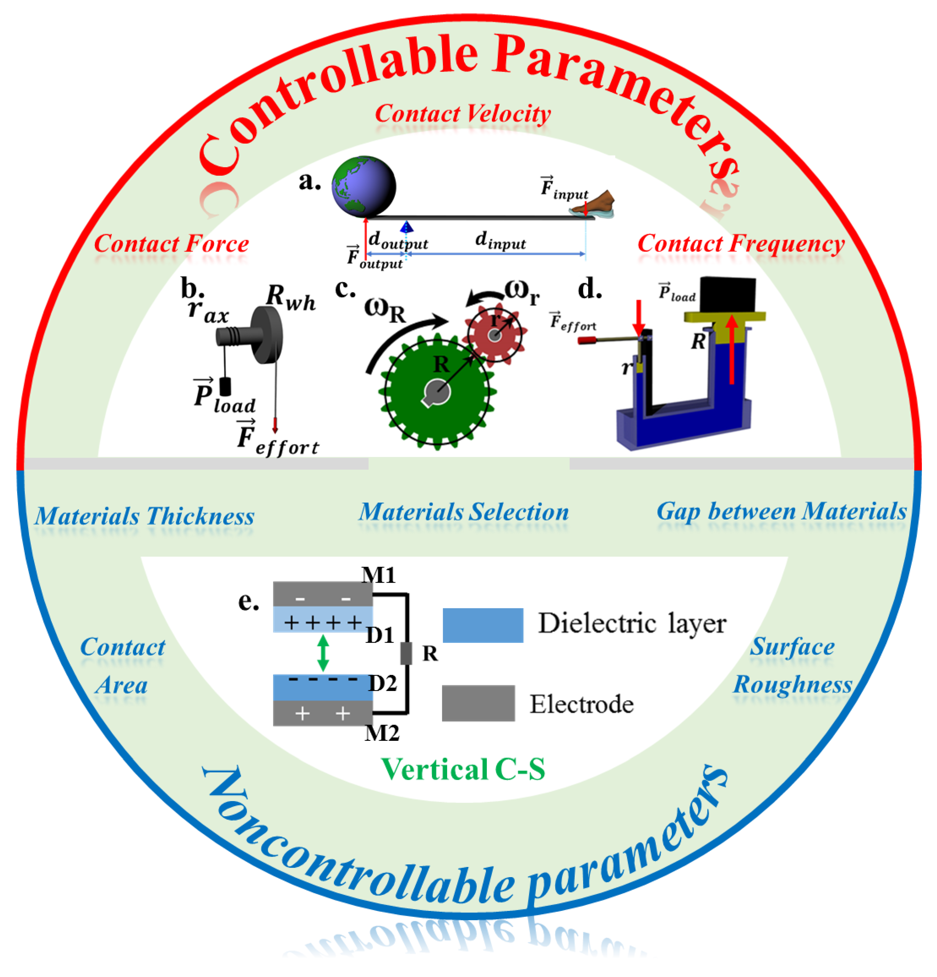
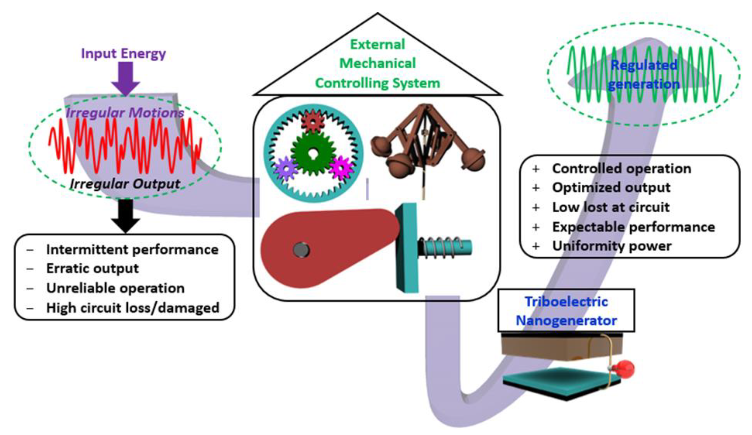
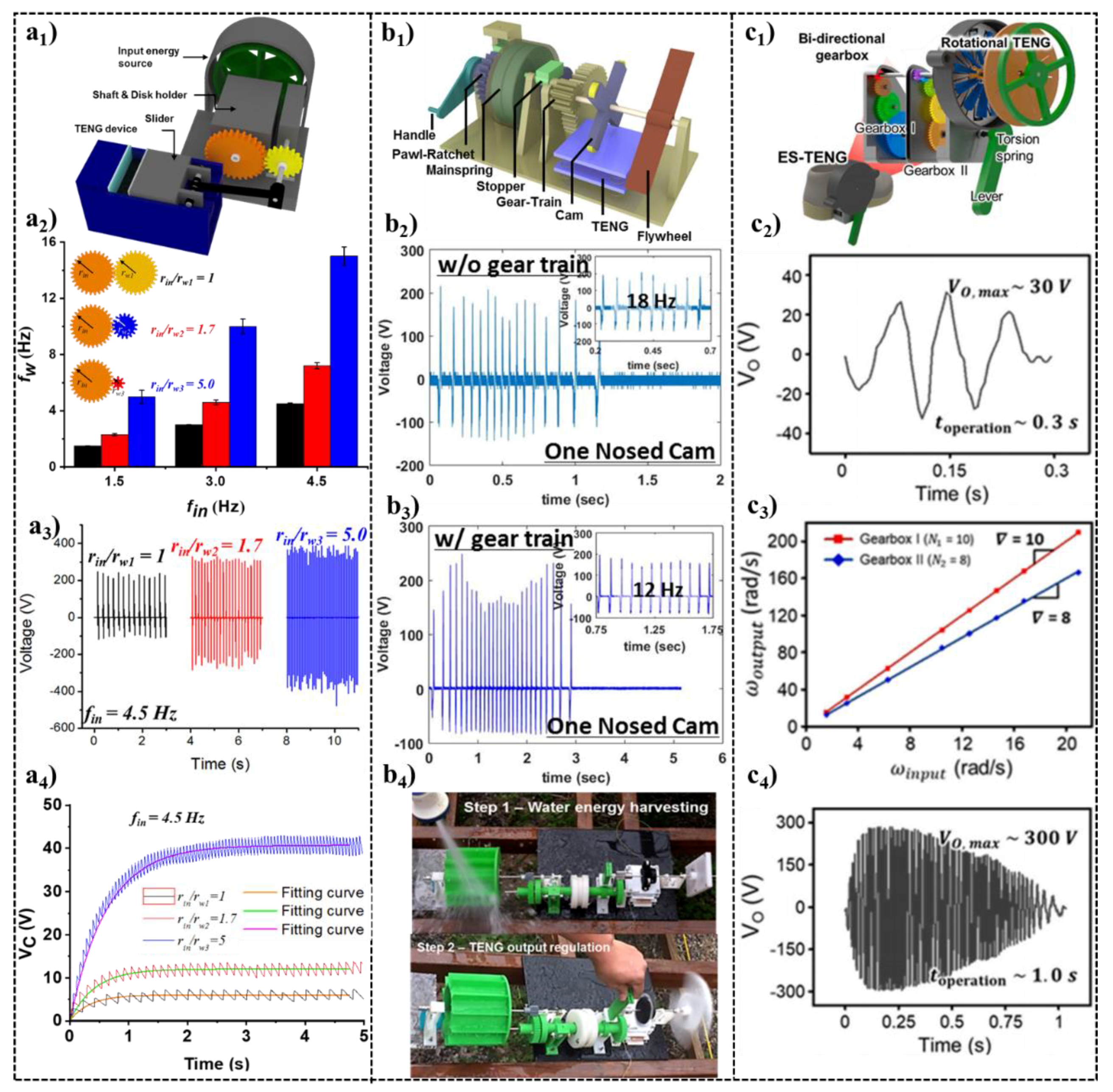
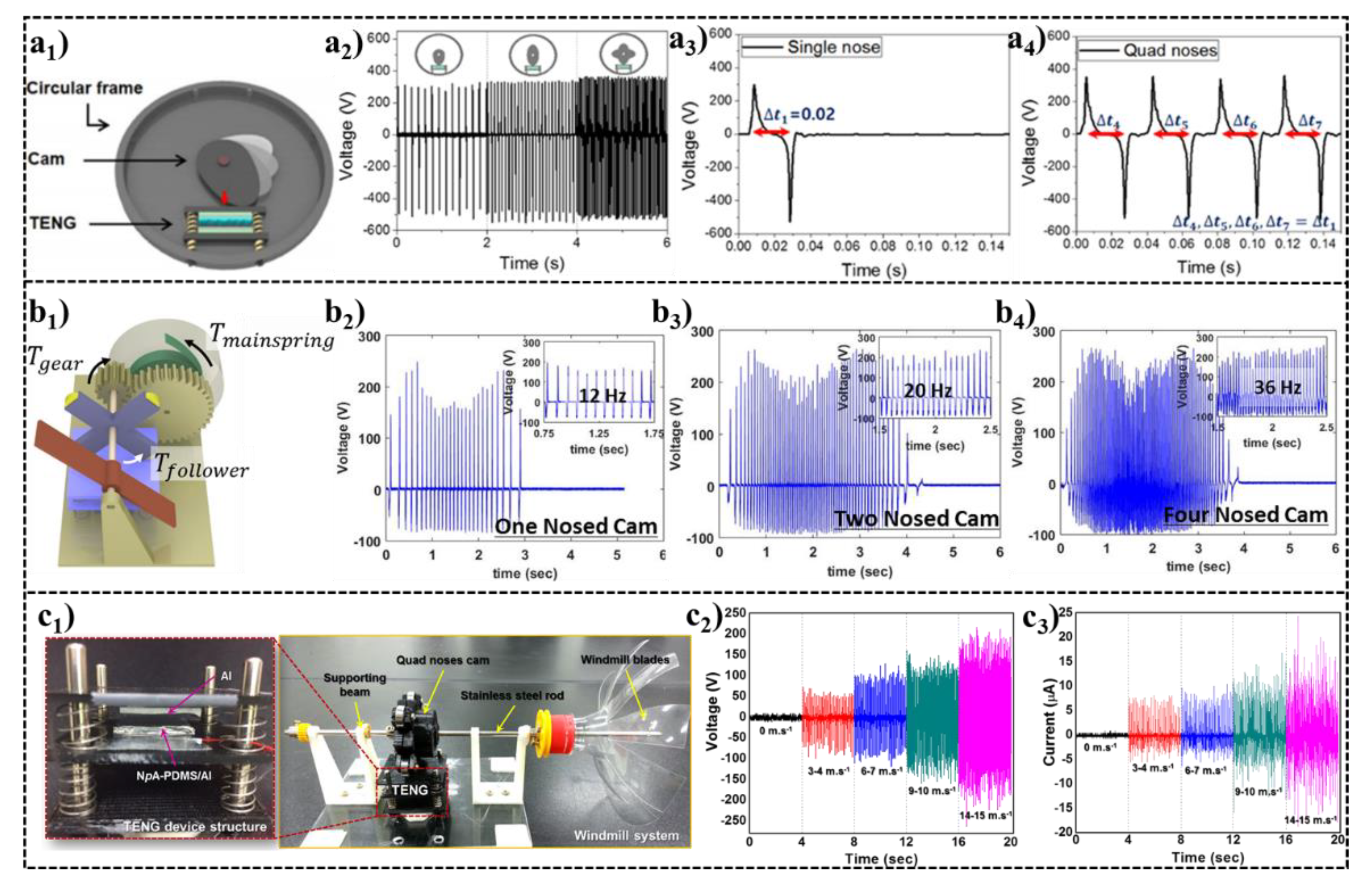
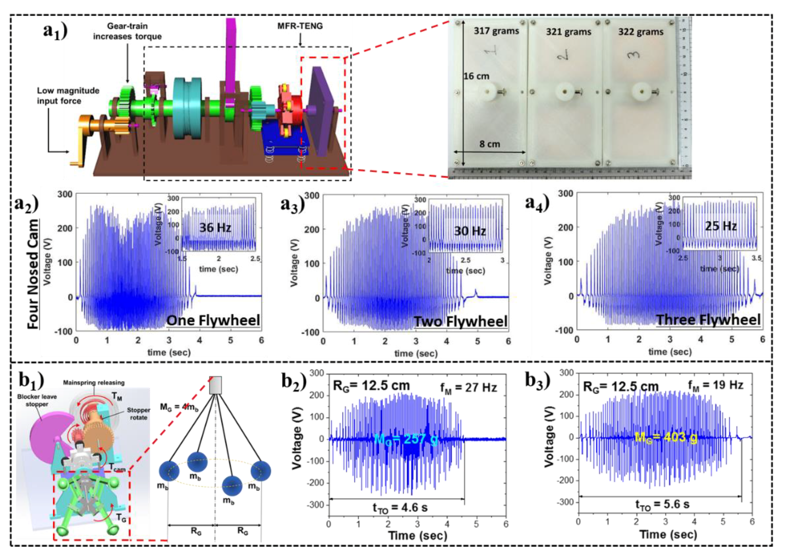
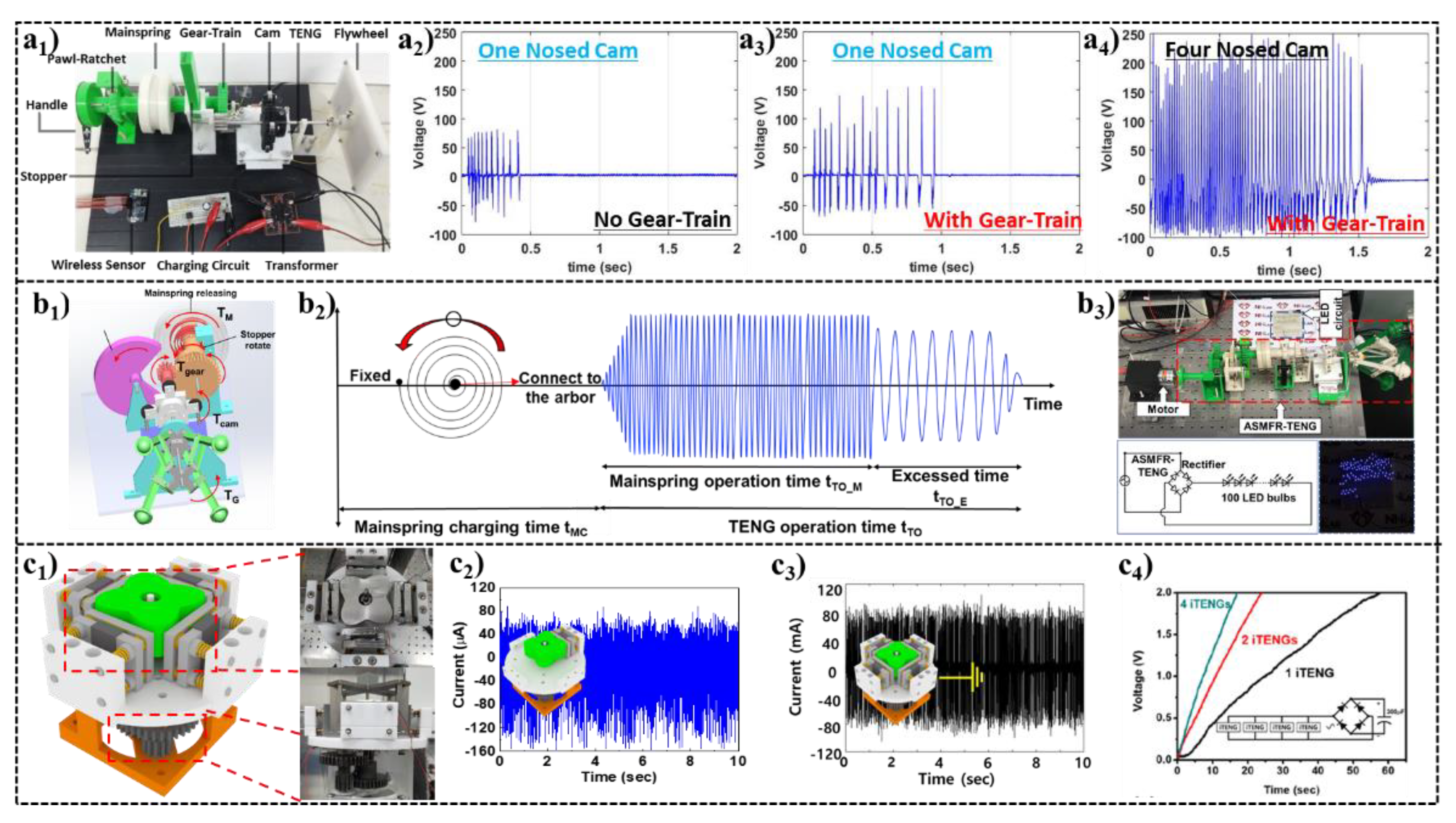
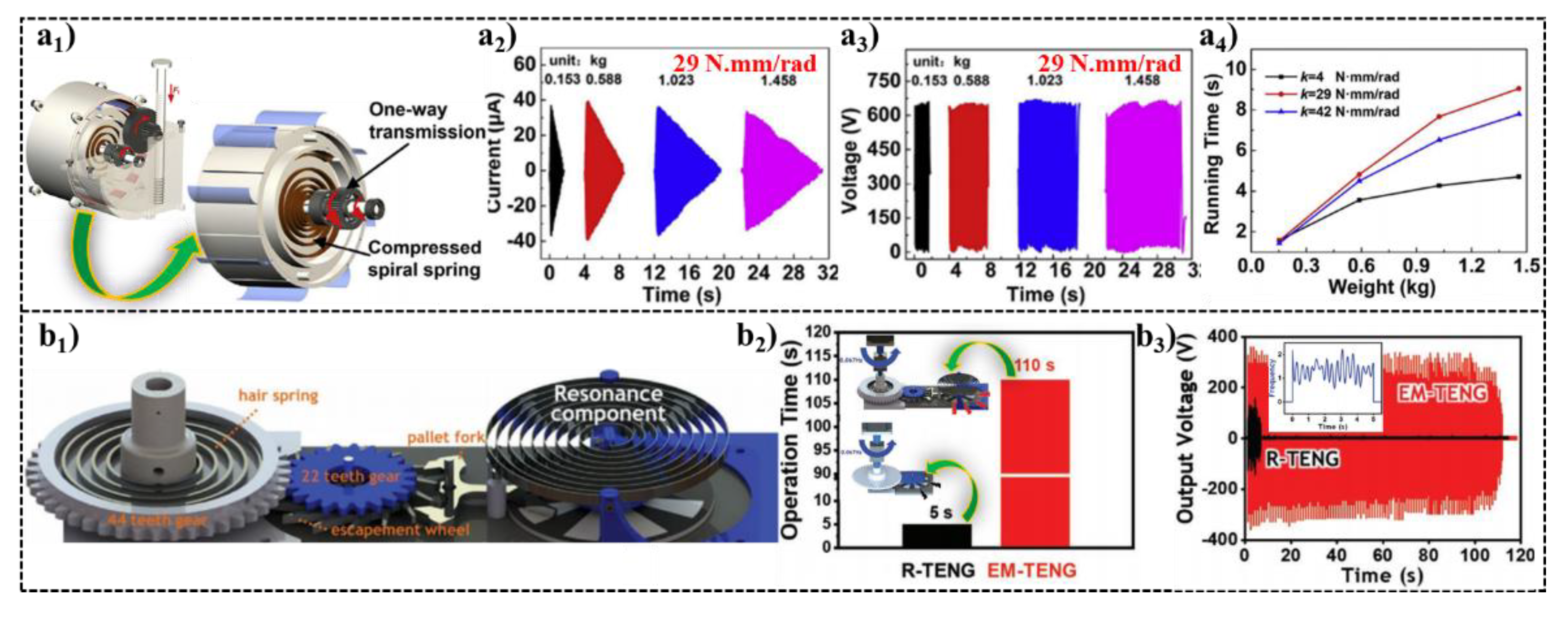
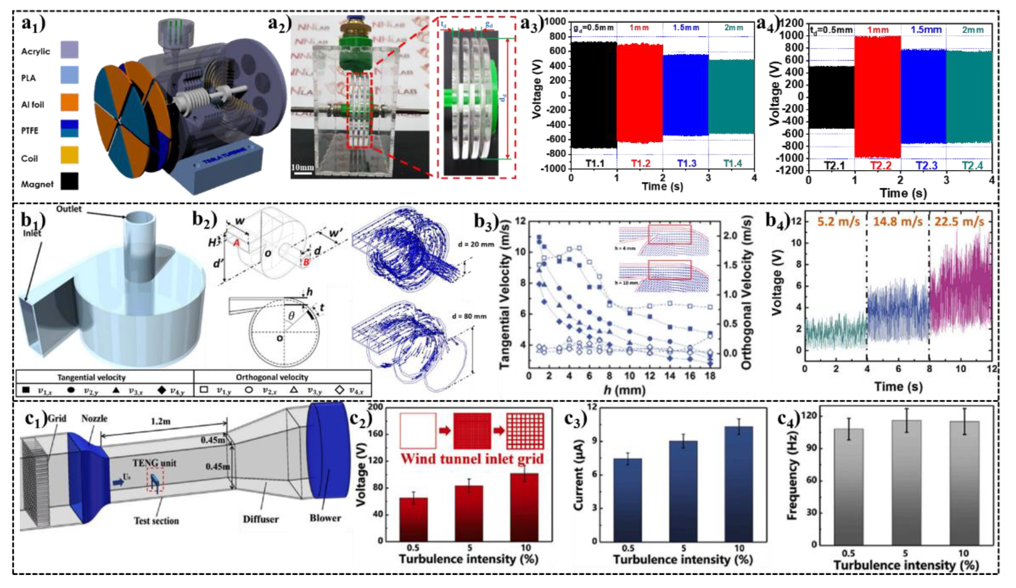
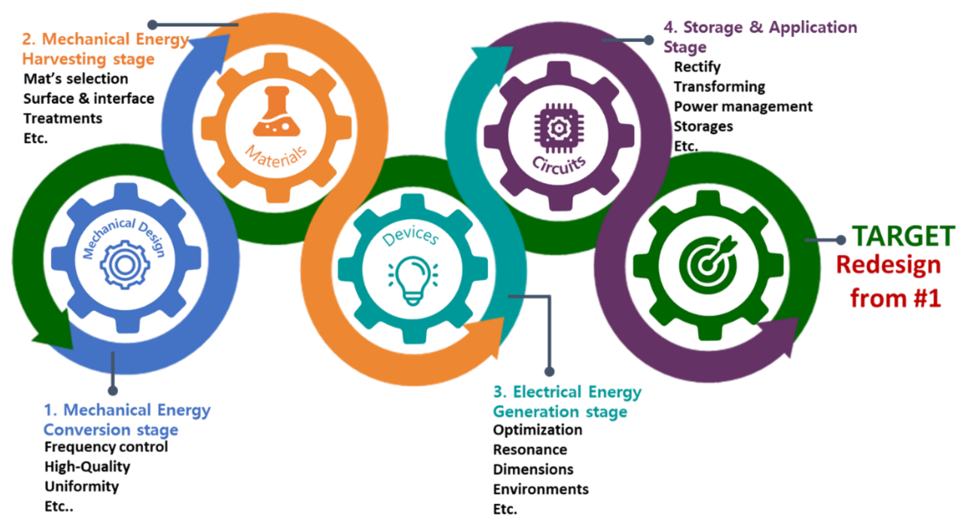
Table 1.
TENG governing equation and control parameters.
| Vertical C-S Mode | Controllability by Mechanical Energy Conversion Systems | |||||||
|---|---|---|---|---|---|---|---|---|
 | Material selection | Material thickness | Material gap | Surface roughness | Contact area | Contact force | Contact velocity | Contact frequency |
| X | X | X | X | X | O | O | O | |
Publisher’s Note: MDPI stays neutral with regard to jurisdictional claims in published maps and institutional affiliations. |
© 2022 by the authors. Licensee MDPI, Basel, Switzerland. This article is an open access article distributed under the terms and conditions of the Creative Commons Attribution (CC BY) license (https://creativecommons.org/licenses/by/4.0/).
Share and Cite
MDPI and ACS Style
Huynh, N.D.; Choi, D. Mechanical Conversion and Transmission Systems for Controlling Triboelectric Nanogenerators. Nanoenergy Adv. 2022, 2, 29-51. https://0-doi-org.brum.beds.ac.uk/10.3390/nanoenergyadv2010002
AMA Style
Huynh ND, Choi D. Mechanical Conversion and Transmission Systems for Controlling Triboelectric Nanogenerators. Nanoenergy Advances. 2022; 2(1):29-51. https://0-doi-org.brum.beds.ac.uk/10.3390/nanoenergyadv2010002
Chicago/Turabian StyleHuynh, Nghia Dinh, and Dukhyun Choi. 2022. "Mechanical Conversion and Transmission Systems for Controlling Triboelectric Nanogenerators" Nanoenergy Advances 2, no. 1: 29-51. https://0-doi-org.brum.beds.ac.uk/10.3390/nanoenergyadv2010002