Solid State Optical Microlasers Fabrication via Microfluidic Channels

1
Photonics Micro-devices Fabrication Lab, Engineering Technology Department, University of North Texas, Denton, TX 76207, USA
2
Mechanical and Energy Engineering Department, University of North Texas, Denton, TX 76207, USA
*
Author to whom correspondence should be addressed.
Optics 2020, 1(1), 88-96; https://0-doi-org.brum.beds.ac.uk/10.3390/opt1010007
Submission received: 10 February 2020
/
Revised: 20 February 2020
/
Accepted: 26 February 2020
/
Published: 1 March 2020
(This article belongs to the Special Issue Fabrication and Applications of Photonic Micro-Devices)
Abstract
:In this paper, we propose the use of a microfluidic channel with flow focusing technique to fabricate solid state polymeric microlasers to precisely control sizes for mass production. Microlasers are made from a solution of UV curable polymer, namely polyethylene glycol diacrylate (PEGDA) with a molecular weight of 700 and rhodamine 6G laser dye at two different volumetric ratios (polymer to dye) of 4:1 and 2:1, respectively, which are used as the dispersed phase. A reservoir filled with liquid polydimethylsiloxane (PDMS) was used to cure the microlasers via UV lamp. A microchannel made of (PDMS) and size of 200 µm was used in this paper; mineral oil was selected as the continuous phase. Two experiments are conducted by fixing the pressure flow for the dispersed phase to 188 mbar and 479.9 mbar, respectively. In both experiments, the pressure of the continuous phase (mineral oil) was varied between 1666.9 mbar and 1996.9 mbar. The measurement of the fabricated microlasers’ size was performed with the aid of the MATLAB Image Processing Toolbox by using photographs taken with a CMOS camera. The tunability of the highest size, ranging from 109 µm to 72 µm, was found for the PEGDA to dye ratio of 2:1 (188 mbar) and average standard deviation of 1.49 µm, while no tunability was found for the 4:1 ratio (188 mbar). The tunability of the microlaser’s size, ranging from 139 µm to 130 µm and an average standard deviation value of 1.47 µm, was found for the 4:1 ratio (479.9 mbar). The fabricated microlasers presented a quality factor Q of the order 104, which is suitable for sensing applications. This technique can be used to control the size of the fabrication of a high number of solid state microlaser based UV polymers mixed with laser dyes.
1. Introduction
Microscale circular structures that enable whispering gallery modes (WGMs) have been employed as passive and active elements for different applications such as non-linear optics, low threshold microlasers, filters, and sensors [1,2,3,4,5,6,7,8,9,10,11,12]. Different materials have been used for the fabrication of these organized microstructures such as polymers, crystals, and other exotic materials [13,14,15]. In addition, various fabrication techniques such as self-assembly, etching, and lithography are typically used [16,17,18]. These WGM based structures (resonators) exhibit a strong light confinement and maintain a long photon lifetime as they exhibit a high-quality factor Q, low mode volume, wide spectral range and mechanical stability, and strong nonlinear interaction. WGM resonators have been also used for building quantum optomechanical devices where the radiative pressure is used to drive mechanical resonances that can be used for extreme sensing applications [19,20,21].
Assuming spherical symmetry and a wavelength of the light that is much larger than the radius of the WGM structure, an approximate ray optic solution can be used to find the optical modes generated inside these resonators; the trapped ray propagates due to the total internal reflection near the surface. When one round trip (2πRn, where n is the refractive index) is equal to l (integer) wavelengths (l is an integer), then a constructive interference will occur, and optical resonances are generated. Any variation of both the refractive index and radius of the resonator leads to a shift of the optical modes, which can be used for sensing purposes [8,9,10,11,12].
Recently, WGM optical neurotransducers for the detection of neuron activities have been proposed by Manzo et al. [22,23]. These neurotransducers are polymeric microlasers doped with a voltage sensitive dye. A voltage sensitive dye (VSD) is used to detect neuron activity via perturbation of the device’s evanescent field, which in turn causes a shift in the laser (optical) modes (WGMs), also eliminating the need for the VSD to be embedded into a cellular membrane [22,23]. Due to this and other sensitive applications, there is the need to fabricate and precisely control the polymeric microlaser size. One of the methods to reach this relatively high precision and high throughput microlaser fabrication is the use of microfluidic channels. Microfluidic channels have been employed to fabricate dye doped droplet microlasers from 10 microns to several hundreds of micrometers [24,25,26,27,28]. However, in all previous works, the fabricated microlasers were tested in the liquid phase, directly from inside the microchannels or by trapping the droplet via optical tweezers [29]. In this paper, we propose the fabrication of solid state optical polymeric microlasers via a microfluidic channel made of polydimethylsiloxane (PDMS). The microlasers were cured in a separated reservoir containing liquid PDMS, then were tested for the emission spectrum and quality factor.
2. Experiments and Methods
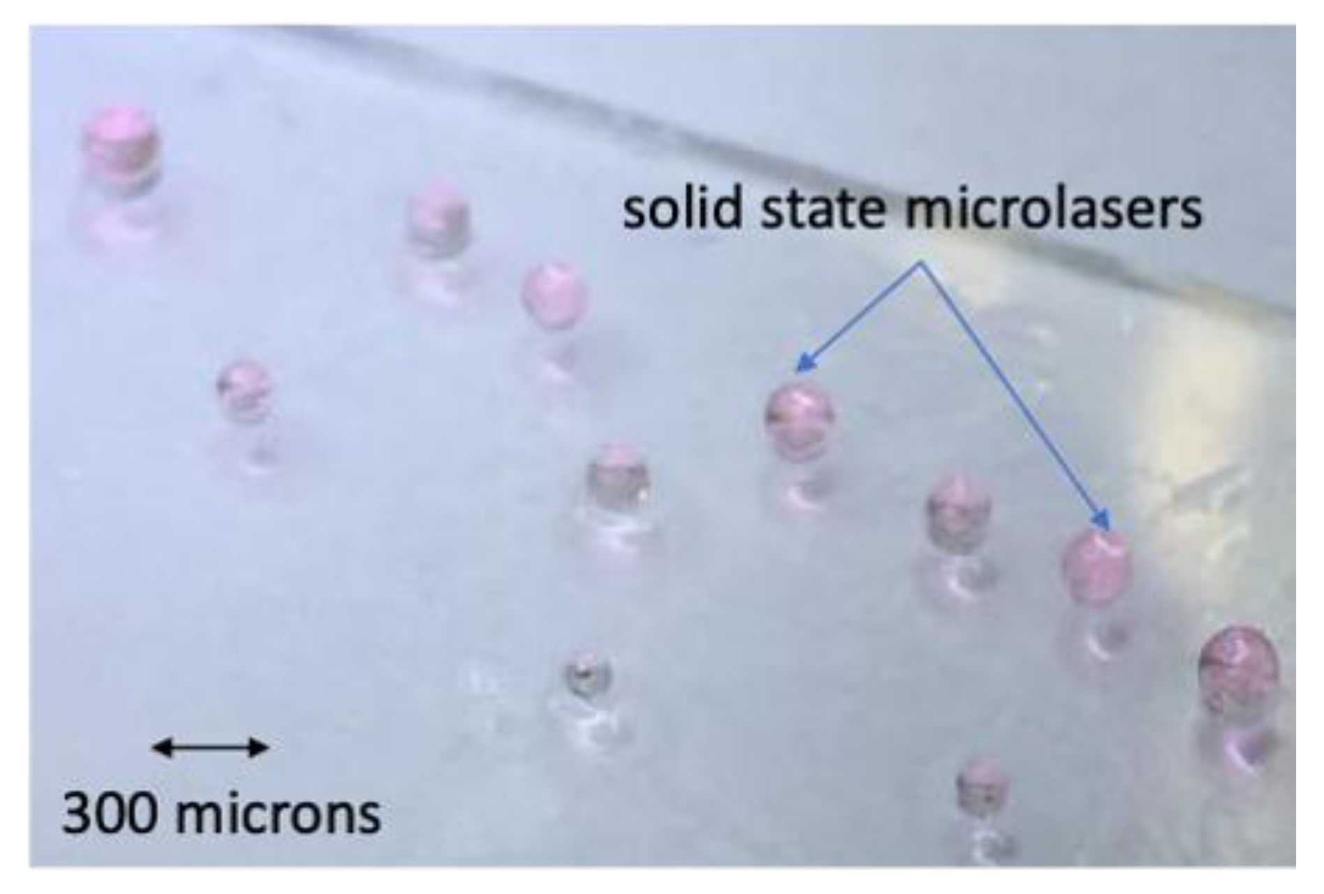
Solid state optical microlasers made of a mixture of UV curable polymer and dye solution have been fabricated by suspending droplets in polydimethylsiloxane (PDMS) liquid polymer. The UV curable polymer and dye solution was chosen to avoid diffusion of the microlaser’s materials into the PDMS. Then, an optical fiber of selected diameter was used to make the droplet into the PDMS reservoir; after that, a UV lamp was used to cure the microlaser that can be extracted from the PDMS and washed out by using a solvent (see Figure 1). However, the microlaser’s size is difficult to reproduce, as is shown in Figure 1. Figure 1 shows the fabricated solid state microlasers using the above described method; the size of the microlasers resulted in a broad range of sizes. In addition, the mass production of microlaser results is difficult, if not impossible.
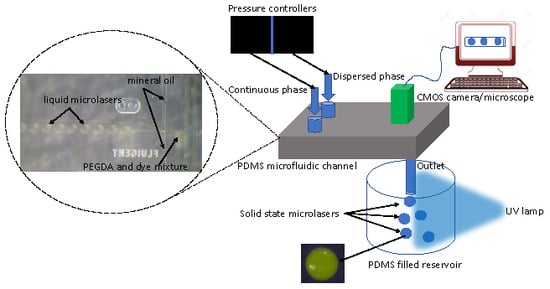
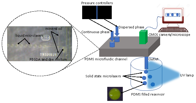
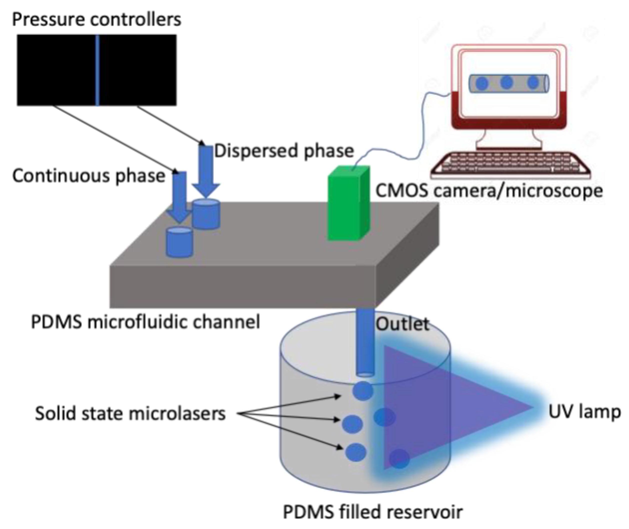
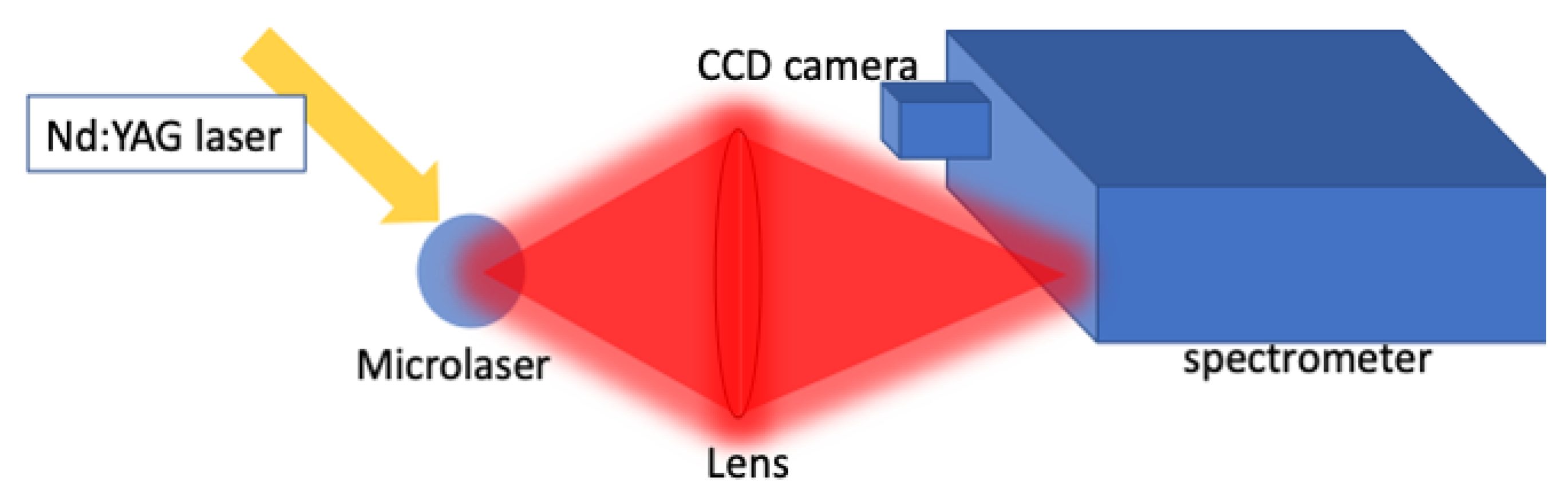
In this paper, we used a microfluidic setup for the fabrication of solid microlasers. The experimental setup used for the fabrication of the optical microlasers is depicted in Figure 2. Two pressure feedback modules (from Fluigent, Lowell, MA 01854) were used for pumping and controlling the fluid flow of both the water and the oil phases. The water phase is a mixture of UV curable polymer and laser dye, while the oil phase is a mineral oil (from Equate). The flow sensors had a resolution of 0.06 /min. A commercial droplet generator made of PDMS (from Fluigent), which uses a flow focusing technique, was connected via tubing to the pressure pumps. The channel size was 200 microns. In addition, the tubing exiting the channel ended in a reservoir filled with liquid PDMS. The reservoir was exposed to a UV lamp with 4-watt power and 365 nm central wavelength. The fabrication process was monitored in real time by an optical microscope focused on the microchannel connected to a CMOS camera. The size of the particles was adjusted by changing the flow parameters (pressure flow) of either the water phase (dispersed phase corresponding to the UV curable polymer and dye solution) or the oil phase (continuous phase corresponding to the mineral oil; generally, the flowrate of the oil phase is increased to make smaller particles. This method allows for the fabrication of a large number of particles with a controlled size. The microlaser was made of a solution of polyethylene glycol diacrylate (PEGDA) with a molecular weight of 700 and rhodamine 6G laser dye (both from Sigma Aldrich). The rhodamine 6G was dissolved in ethanol with a concentration of 10−4 molar. Two different volumetric ratios between the polymer and the dye were used in this research of 4:1 and 2:1, respectively. PEGDA polymer was used in previous works due to its good optical and mechanical properties; in addition, this polymer is hydrophilic, which results in compatibility with the PDMS hydrophobic channel for generating droplets [30,31]. After the microlaser was cured, it was extracted from the liquid PDMS, put on a glass support, and washed out with isopropyl alcohol. After the solvent evaporation, the microlaser was ready for testing the emission spectrum with the setup depicted in Figure 3; a Q-switch Nd:YAG laser was used as the external excitation light source with a pulse repetition of 10 Hz and a pulse linewidth of 5 ns; the beam diameter was ~0.7 cm. The energy from the laser was measured using a pyroelectric sensor. The light emitted from the microlaser was collected through an optical lens, which in turn was focused at the entrance slit of a high-resolution spectrometer. A cooled CCD camera (−30 °C) was mounted at the exit slit of the spectrometer and was used to monitor the emission from the tested microlasers.
In this paper, the production of microlasers was made by considering the flow pressure of both the aqueous solution and oil solution; the flow pressure for the water phase (dispersed phase) was maintained at constant, while the one for the continuous phase (oil phase) was varied for the 4:1 and 2:1 ratios of PEGDA and dye mixture (in volume). After each experiment, the microchannel and tubing were flushed with 91% isopropyl alcohol for approximately 30 min, in order to prevent the UV curable polymer from solidifying and obstructing the system. In addition, a second experiment was made by rising the fixed value of the dispersed phase for the PEGDA to dye mixture ratio of 4:1 (volume) and by letting the pressure flow of the continuous phase vary from 1666.9 mbar to 1996.9 mbar.
3. Results and Discussion
The first set of experiments was conducted by fixing the pressure controller for the aqueous phase (dispersed phase) while the oil phase (continuous phase) pressure was varied from 1666.9 mbar to 1996.9 mbar, as described earlier.
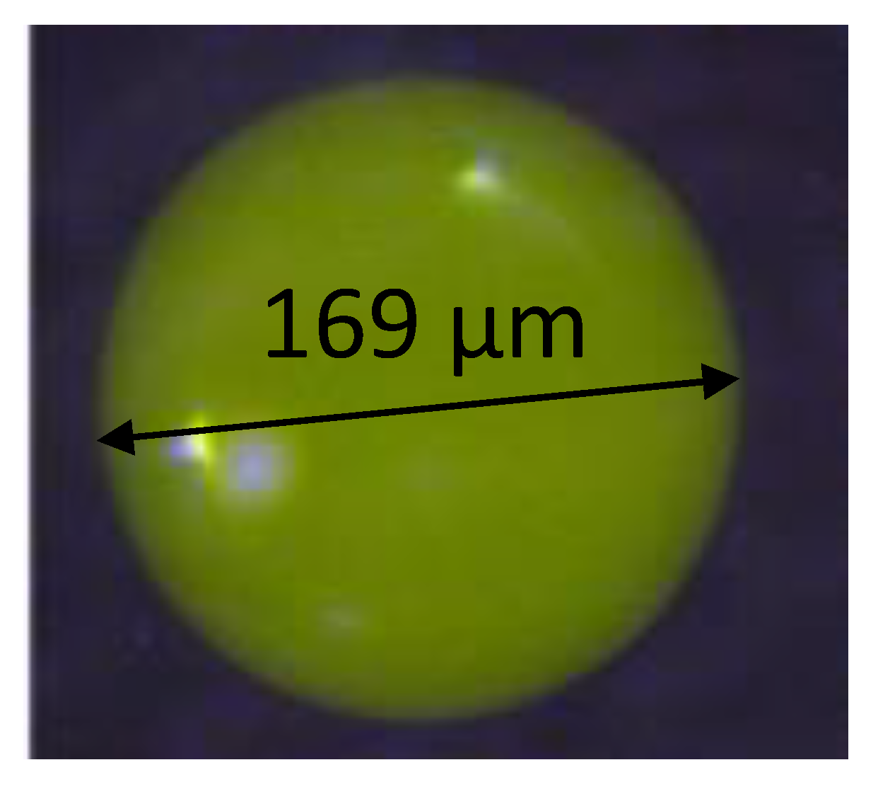
Figure 4 shows a photograph taken by using a CMOS camera connected to a microscope of one of the fabricated microlasers. The device exhibited a clean surface and was free of major roughness, which would limit the lasing capability of the microlaser. As described earlier, the liquid microlaser was first cured in a separated reservoir filled with liquid polymer (PDMS). Then, the microlaser was extracted from the reservoir and placed on a microscope glass together with isopropyl alcohol to wash out the residual PDMS; the process maintained the surface integrity of the microlaser.
Figure 5 shows the experimental results in terms of the sizes of the microlasers, represented by the diameter, as the function of the pressure pump of the continuous phase (mineral oil) for the PEGDA to dye ratio of 4:1 in volume. The pressure of the dispersed phase was fixed at 188 mbar. Each data point of the graph represents the mean of the diameters of the produced microlasers at a selected pressure value (continuous phase). As Figure 5 shows, the size of the microlasers was almost constant with the changing of the pressure of the mineral oil. The average size’s value was found to be 168.7 µm with an average standard deviation value of 1.79 µm.
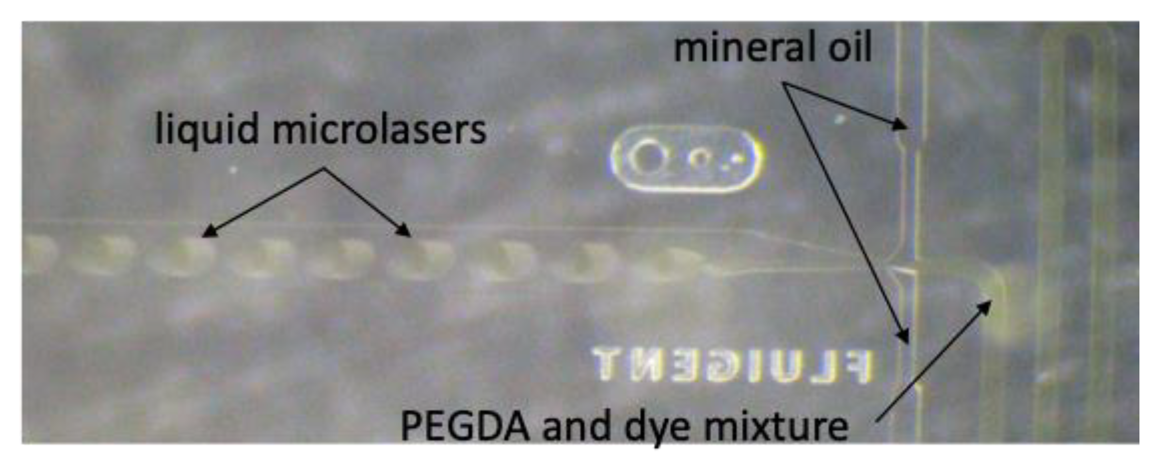
To estimate the microlaser’s sizes during these experiments, photographs were taken with a CMOS camera connected to an optical microscope (Figure 6). In Figure 6, in addition to the liquid microlasers, is it possible to also both the dispersed (PEGDA and dye mixture) and continuous (mineral oil) phase flows. These photographs were analyzed by using the MATLAB Image Processing Toolbox. The values were compared with the microlaser sizes found by visual inspection with the aid of a ruler printed on the microfluidic chip. We found a discrepancy in the microlasers’ sizes of ~10%. This can be due to the fact that the toolbox creates a better contrast of the particle’s contour geometry, resulting in a more precise measurement.
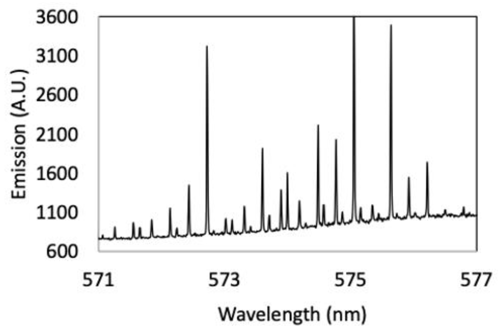
Figure 7 shows the emission spectrum from one of the fabricated microlasers made with the fixed value of 188 mbar. The microlaser was made of PEGDA and dye solution with a ratio of 4:1 in volume and its size was measured as 170.2 µm in diameter. The energy used for this experiment was 17.26 µj/cm2. The spectrum result was clean as shown in Figure 7; thus, the shift in the optical modes can be easily determined. Therefore, the solid state optical microlasers can be used for applications such as sensing. The average Q factor value was 2.9 × 10⁴ and was comparable with the Q factor found in microlasers fabricated with other techniques. The quality factor Q is a measure of how resolute a sensor based on optical microlasers [1,2,3,4,5,9,10]. This means that the fabrication method did not affect the quality factor of the microlasers, or that the variation of the Q factor was below the instrument resolution.
Figure 8 shows the microlasers’ diameters as a function of the pressure pump of the continuous phase (mineral oil) for the PEGDA to dye ratio of 2:1 in volume. The pressure of the dispersed phase was fixed at 188 mbar. As Figure 8 shows, the size of the microlasers varied from ~109 µm at lower pressure to ~72 µm at higher pressure. This can be explained by the fact that the mixture ratio of 2:1 exhibited a more viscous dispersed phase; therefore, the shear forces at the microchannel walls have a more prominent effect on the microlaser’s size with the variation of pressure for the continuous phase. This can be an advantage when a higher tunability range for the produced microlasers is desired without changing the microfluidic channel size. The average Q factor value was found to be 3.5*104 and it was comparable with the Q factor found in microlasers fabricated with the PEGDA and dye solution at 4:1 (in volume). The average standard deviation value was found to be 1.49 µm, which was close to the one found from the previous case.
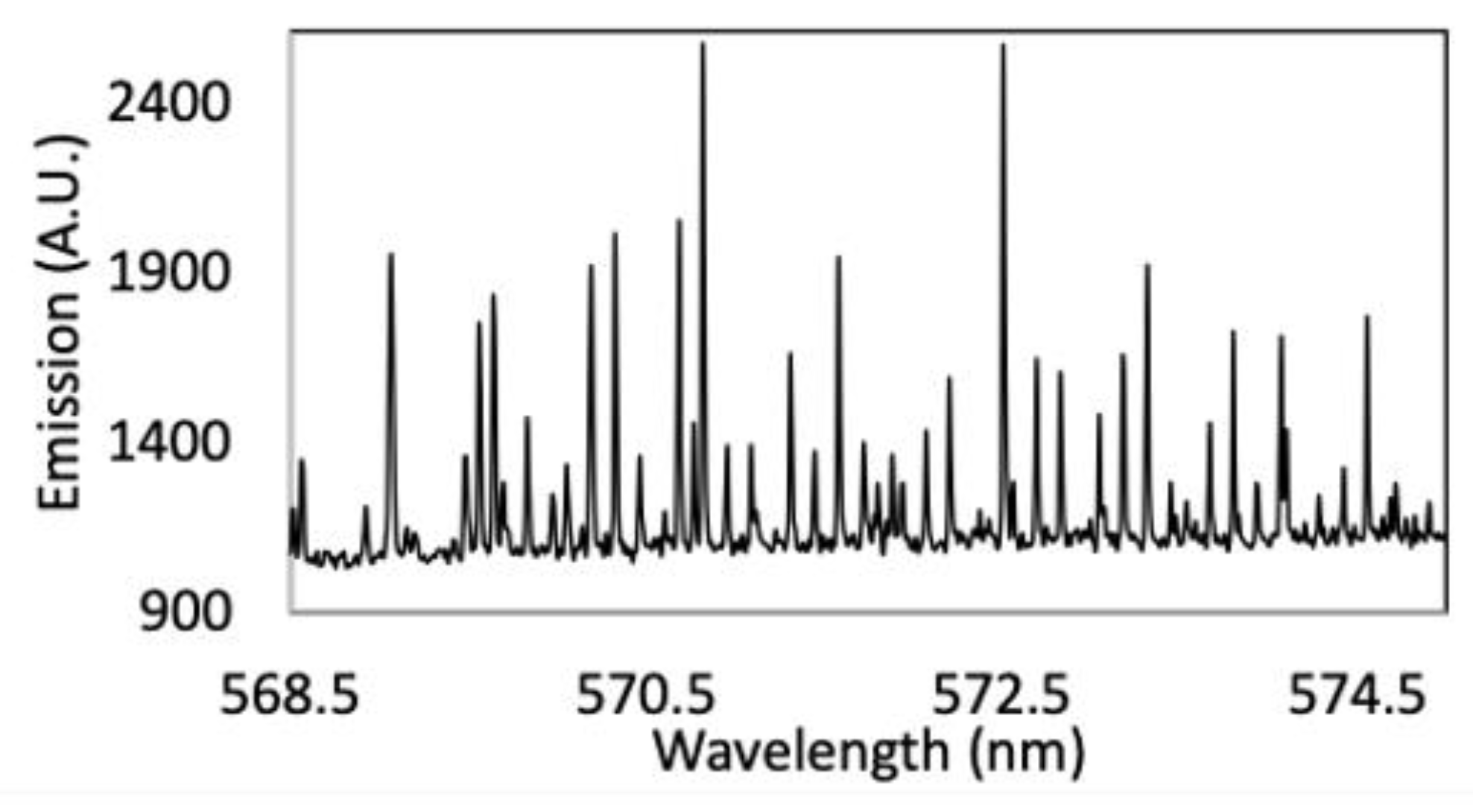
Figure 9 shows the emission spectrum from one of the fabricated microlasers with a 2:1 ratio, the size was 108 µm in diameter. The energy used for this experiment was 17.26 µj/cm2. The spectrum taken from the microlaser results was as clean as the one from the previous case and therefore suitable for sensing applications.
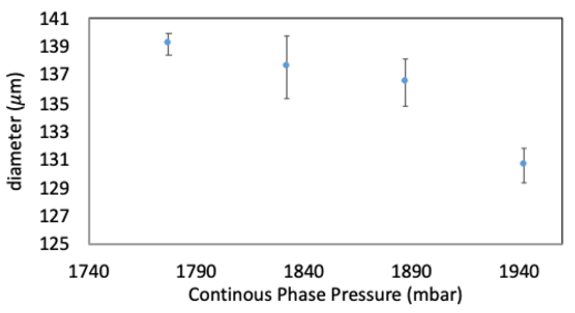
The second set of experiments was conducted by changing the fixed pressure value (from 188 mbar to 479.9 mb) for the aqueous phase (dispersed phase) while the oil phase (continuous phase) pressure varied from 1666.9 mbar to 1996.9 mbar as for the previous cases. Figure 10 shows the microlasers’ diameters as a function of the pressure pump of the continuous phase (mineral oil) for the PEGDA to dye ratio of 4:1 in volume. As Figure 10 shows, the microlasers’ size varied from ~139 µm at lower pressure to ~130 µm at the higher pressure value selected for these experiments. The average standard deviation value was found to be 1.47 µm, which was slightly better than the case with a lower fixed dispersed pressure value. In addition, a slightly higher size’s tunability is possible for microlasers built with a higher dispersed pressure value.
4. Conclusions
The fabrication process of solid state microlasers via microfluidic channels was demonstrated. The microlaser was made of UV curable polymer PEGDA 700 doped with rhodamine 6G. Two different PEGDA to dye ratios were used in this paper, 4:1 and 2:1 (in volume). A PDMS microfluidic system based on the flow focusing technique and a channel size of 200 µm was used for the fabrication of the microlasers. The pressure of the dispersed phase (PEGDA and dye mixture) was fixed at 188 mbar while the pressure of the continuous phase (mineral oil) was varied between 1666.9 mbar and 1996.9 mbar. The same experiment was repeated for a fixed dispersed pressure value of 479.9 mbar for the 4:1 ratio polymer to dye mixture. The microlasers were collected into a separate reservoir filled with liquid PDMS where they were cured via UV light and washed out with isopropyl alcohol. It was found that all configurations reported a quality factor Q of the order 104 (using a fluence of 17.26 µj/cm2), which was comparable to polymeric microlasers fabricated with other techniques. MATLAB Image Processing Toolbox was used to measure the fabricated microlasers’ size from photographs taken with a CMOS camera connected to a microscope. The highest size’s tunability (from 109 µm to 72 µm) was obtained with a pressure value for the dispersed phase of 188 mbar and for the PEGDA to dye ratio of 2:1; the average standard deviation was found to be 1.49 µm, which was mainly due to the higher viscosity of this mixture. In addition, by increasing the fixed pressure value for the dispersed phase, it was found that the microlasers’ size tunability ranged from 139 µm to 130 µm with an average standard deviation value of 1.47 µm. The 4:1 PEGDA to polymer ratio (with fixed pressure of 188 mbar) was found to have a fixed microlaser size of about 168.7 µm with an average standard deviation value of 1.79 µm.
The presented method can be used when a high number of solid state microlasers made of UV polymer and dye mixture need to be produced with high repeatability.
Author Contributions
Conceptualization, M.M.; methodology, M.M.; formal analysis, M.M.; investigation, O.C.; resources, M.M.; data curation, M.M. and O.C.; writing—original draft preparation, M.M.; writing—review and editing, M.M.; visualization, M.M.; supervision, M.M. All authors have read and agreed to the published version of the manuscript.
Funding
This research received no external funding.
Conflicts of Interest
The authors declare no conflicts of interest.
References
- Strekalov, D.V.; Marquardt, C.; Matsko, A.B.; Schwefel, H.G.L.; Leuchs, G. Nonlinear and quantum optics with whispering gallery resonators. J. Opt. 2016, 18, 123002. [Google Scholar] [CrossRef] [Green Version]
- Li, Y.; Jiang, X.; Zhao, G.; Yang, L. Whispering gallery mode microresonator for nonlinear optics. arXiv 2018, arXiv:1809.04878. [Google Scholar]
- Hsu, H.-S.; Cai, C.; Armani, A.M. Ultra-low-threshold Er:Yb sol-gel microlaser on silicon. Opt. Express 2017, 17, 23265–23271. [Google Scholar] [CrossRef] [Green Version]
- Manzo, M. Temperature compensation of dye doped polymeric microscale lasers. J. Polym. Sci. Part B 2017, 55, 789–792. [Google Scholar] [CrossRef]
- Cavazos, O.; Manzo, M.; Ramírez-Cedillo, E.; Siller, H.R. Bone-Integrated Optical Microlasers for In-Vivo Diagnostic Biomechanical Performances. In Proceedings of the ASME 2019 International Mechanical Engineering Congress and Exposition, Salt Lake City, UT, USA, 11–14 November 2019. [Google Scholar]
- Savchenkov, A.A.; Matsko, A.B.; Strekalov, D.; Ilchenko, V.S.; Maleki, L. Mode filtering in optical whispering gallery resonators. Electron. Lett. 2005, 41, 1. [Google Scholar] [CrossRef]
- Matsko, A.B.; Liang, W.; Savchenkov, A.; Ilchenko, V.; Seidel, D.; Maleki, L. Multi-octave tunable agile RF photonic filters. In Proceedings of the 2012 IEEE International Topical Meeting on Microwave Photonics, Noordwijk, The Netherlands, 11–14 September 2012. [Google Scholar]
- Foreman, M.R.; Swaim, J.D.; Vollmer, F. Whispering gallery mode sensors. Adv. Opt. Photonics 2015, 7, 168–240. [Google Scholar] [CrossRef]
- Manzo, M.; Ioppolo, T. Untethered photonic sensor for wall pressure measurement. Opt. Lett. 2015, 40, 2257–2280. [Google Scholar] [CrossRef]
- Manzo, M.; Ioppolo, T.; LaPenna, V.; Ayaz, U.; Otugen, V. A photonic wall pressure sensor for fluid mechanics applications. Rev. Sci. Instrum. 2012, 83, 105003. [Google Scholar] [CrossRef]
- Xu, X.; Chen, W.; Zhao, G.; Li, Y.; Lu, C.; Yang, L. Wireless whispering-gallery mode sensor for thermal sensing and aerial mapping. Light Sci. Appl. 2018, 62, 1–6. [Google Scholar] [CrossRef]
- Rosenblum, S.; Lovsky, Y.; Arazi, L.; Vollmer, F.; Dayan, B. Cavity ring-up spectroscopy for ultrafast sensing with optical microresonators. Nat. Commun. 2015, 6, 6788. [Google Scholar] [CrossRef]
- Kuwata-Gonokami, M.; Takeda, K. Polymer whispering gallery mode lasers. Opt. Mater. 1998, 9, 12–17. [Google Scholar] [CrossRef]
- Savchenkov, A.A.; Ilchenko, V.S.; Matsko, A.B.; Maleki, L. Kilohertz optical resonances in dielectric crystal cavities. Phys. Rev. A 2004, 70, 051804. [Google Scholar] [CrossRef]
- Falconi, M.C.; Starecki, F.; Nazabal, V.; Bodiou, L.; Dumeige, Y.; Lemaitre, J.; Charrier, J.; Prudenzano, F. Design of rare-earth doped chalcogenide microresonators for biosensing in Mid-IR. In Proceedings of the 2016 18th International Conference on Transparent Optical Networks (ICTON), Trento, Italy, 10–14 July 2016. [Google Scholar]
- Ta, V.D.; Chen, R.; Sun, H.D. Tuning whispering gallery mode lasing from self-assembled Polymer droplets. Sci. Rep. 2013, 3, 1362. [Google Scholar] [CrossRef]
- Gayral, B.; Gérard, J.M.; Lemaitre, A.; Dupuis, C.; Manin, L.; Pelouard, J.L. High-Q wet-etched GaAs microdisks containing InAs quantum boxes. Appl. Phys. Lett. 1999, 75, 1908–1910. [Google Scholar] [CrossRef]
- Brenner, P.; Bar-On, O.; Siegle, T.; Leonhard, T.; Gvishi, R.; Eschenbaum, C.; Kalt, H.; Scheuer, J.; Lemmer, U. 3D whispering-gallery mode microlasers by direct laser writing and subsequent soft nanoimprint lithography. Appl. Opt. 2017, 56, 3703–3708. [Google Scholar] [CrossRef]
- Matsko, A.B.; Savchenkoc, A.A.; Ilchenko, V.S.; Seidel, D.; Maleki, L. Optomechanics with surface-acoustic wave whispering-gallery modes. Phys. Rev. Lett. 2009, 103, 257403. [Google Scholar] [CrossRef] [Green Version]
- Ding, L.; Baker, C.; Senellart, P.; Lemaitre, A.; Ducci, S.; Leo, G.; Favero, I. Wavelength-sized GaAs optomechanical resonators with gigahertz frequency. Appl. Phys. Lett. 2011, 98, 113108. [Google Scholar] [CrossRef] [Green Version]
- Kippenberg, T.J.; Vahala, K.J. Cavity optomechanics: Back-action at the mesoscale. Science 2008, 321, 1172–1176. [Google Scholar] [CrossRef] [Green Version]
- Manzo, M.; Cavazos, O. Neurotransducers Based Voltage Sensitive Dye-Doped Microlasers. In Proceedings of the Biophotonics Congress: Optics in the Life Sciences Congress 2019, Tucson, AZ, USA, 15–17 April 2019. [Google Scholar]
- Manzo, M.; Olokodana, I.L. Emission Spectrum Denoising Algorithm for Microlasers-Based Neurotransducers. In Proceedings of the OSA Advanced Photonics Congress (AP) 2019, Burlingame, CA, USA, 29 July–1 August 2019. [Google Scholar]
- Zhao, L.; Wang, Y.; Yuan, Y.; Liu, Y.; Liu, S.; Sun, W.; Yang, J.; Li, H. Whispering gallery mode laser based on cholesteric liquid crystal microdroplets as temperature sensor. Opt. Commun. 2017, 402, 181–185. [Google Scholar] [CrossRef]
- Tang, S.K.Y.; Li, Z.; Abate, A.R.; Agresti, J.J.; Weitz, D.A.; Psaltis, D.; Whitesides, G.M. A multi-color fast-switching microfluidic droplet dye laser. Lab Chip 2009, 9, 2767–2771. [Google Scholar] [CrossRef] [Green Version]
- Kuehne, A.J.C.; Gather, M.C.; Evdelnant, I.A.; Yun, S.-H.; Weitz, D.A.; Wheeler, A.R. A Switchable digital microfluidic droplet dye-laser. Lab Chip 2011, 11, 3716–3719. [Google Scholar] [CrossRef] [Green Version]
- Zheng, L.; Zhi, M.; Chan, Y.; Khan, S.A. Embedding liquid lasers within or around aqueous microfluidic droplets. Lab Chip 2018, 18, 197–205. [Google Scholar] [CrossRef]
- Tang, S.K.Y.; Derda, R.; Quan, Q.; Lončar, M.; Whitesides, G.M. Continuously tunable microdroplet-laser in a microfluidic channel. Opt. Express 2011, 19, 2204–2215. [Google Scholar] [CrossRef]
- Liu, Z.; Liu, L.; Zhu, Z.; Zhang, Y.; Wei, Y.; Zhang, X.; Zhao, E.; Zhang, Y.; Yang, J.; Yuan, L. Whispering gallery mode temperature sensor of liquid microresonator. Opt. Lett. 2016, 41, 4649–4652. [Google Scholar] [CrossRef]
- Ma, S.; Thiele, J.; Bai, Y.; Abell, C.; Huck, W.T.S. Fabrication of microgel particles with complex shape via selective polymerization of aqueous two-phase systems. Small 2012, 8, 2356–2360. [Google Scholar] [CrossRef]
- Morris, V.B.; Nimbalkar, S.; Younesi, M.; McClellan, P.; Akkus, O. Mechanical properties, cytocompatibility and manufacturability of chitosan: PEGDA hybrid-gel scaffolds by stereolithography. Ann. Biomed. Eng. 2017, 45, 286–296. [Google Scholar] [CrossRef]
Figure 1.
Solid state microlasers on a microscope glass.

Figure 2.
Experimental setup used for the fabrication and observation of optical microlasers.

Figure 3.
Experimental setup used to test the microlasers.

Figure 4.
Photograph of a solid state microlaser made via the microfluidic channel.

Figure 5.
Microlaser size (4:1 ratio) produced with fixed pressure for the dispersed phase (188 mbar) and a variable pressure of the continuous phase.
Figure 5.
Microlaser size (4:1 ratio) produced with fixed pressure for the dispersed phase (188 mbar) and a variable pressure of the continuous phase.

Figure 6.
Photograph taken with the CMOS camera of the microfluidic channels and the microlasers in the liquid phase.
Figure 6.
Photograph taken with the CMOS camera of the microfluidic channels and the microlasers in the liquid phase.

Figure 7.
Emission spectrum from the solid state microlaser (polymer to dye 4:1 ratio) fabricated with a fixed dispersed pressure of 188 mbar.
Figure 7.
Emission spectrum from the solid state microlaser (polymer to dye 4:1 ratio) fabricated with a fixed dispersed pressure of 188 mbar.

Figure 8.
Microlaser size (2:1 ratio) produced with fixed pressure for the dispersed phase (188 mbar) and a variable pressure of the continuous phase.
Figure 8.
Microlaser size (2:1 ratio) produced with fixed pressure for the dispersed phase (188 mbar) and a variable pressure of the continuous phase.

Figure 9.
Emission spectrum from the solid state microlaser (polymer to dye 2:1 ratio) fabricated with a fixed dispersed pressure of 188 mbar.
Figure 9.
Emission spectrum from the solid state microlaser (polymer to dye 2:1 ratio) fabricated with a fixed dispersed pressure of 188 mbar.

Figure 10.
Microlaser size (4:1 ratio) produced with fixed pressure for the dispersed phase (479.9 mbar) and a variable pressure of the continuous phase.
Figure 10.
Microlaser size (4:1 ratio) produced with fixed pressure for the dispersed phase (479.9 mbar) and a variable pressure of the continuous phase.

© 2020 by the authors. Licensee MDPI, Basel, Switzerland. This article is an open access article distributed under the terms and conditions of the Creative Commons Attribution (CC BY) license (http://creativecommons.org/licenses/by/4.0/).
Share and Cite
MDPI and ACS Style
Manzo, M.; Cavazos, O. Solid State Optical Microlasers Fabrication via Microfluidic Channels. Optics 2020, 1, 88-96. https://0-doi-org.brum.beds.ac.uk/10.3390/opt1010007
AMA Style
Manzo M, Cavazos O. Solid State Optical Microlasers Fabrication via Microfluidic Channels. Optics. 2020; 1(1):88-96. https://0-doi-org.brum.beds.ac.uk/10.3390/opt1010007
Chicago/Turabian StyleManzo, Maurizio, and Omar Cavazos. 2020. "Solid State Optical Microlasers Fabrication via Microfluidic Channels" Optics 1, no. 1: 88-96. https://0-doi-org.brum.beds.ac.uk/10.3390/opt1010007