Optimising the AR Engraved Structure on Light-Guide Facets for a Wide Range of Wavelengths


1
Photonics and Electro-Optics Engineering Unit, Ben-Gurion University, Beer-Sheva 8410501, Israel
2
Department of Electrotechnics and Electronics, Academic College Sami Shamoon, Beer-Sheva 8410802, Israel
*
Author to whom correspondence should be addressed.
Optics 2021, 2(1), 25-42; https://0-doi-org.brum.beds.ac.uk/10.3390/opt2010002
Submission received: 9 December 2020
/
Revised: 22 December 2020
/
Accepted: 25 December 2020
/
Published: 31 December 2020
Abstract
:The present study is aimed at designing anti-reflective (AR) engraving on the input–output surfaces of a rectangular light-guide. We estimate AR efficiency, by the transmittance level in the angular range, determined by the light-guide. Using nano-engraving, we achieve a uniform high transmission over a wide range of wavelengths. In the past, we used smoothed conical pins or indentations on the faces of light-guide crystal as the engraved structure. Here, we widen the class of pins under consideration, following the physical model developed in the previous paper. We analyze the smoothed pyramidal pins with different base shapes. The possible effect of randomization of the pins parameters is also examined. The results obtained demonstrate optimized engraved structure with parameters depending on the required spectral range and facet format. The predicted level of transmittance is close to 99%, and its flatness (estimated by the standard deviation) in the required wavelengths range is 0.2%. The theoretical analysis and numerical calculations indicate that the obtained results demonstrate the best transmission (reflection) we can expect for a facet with the given shape and size for the required spectral band. The approach is equally useful for any other form and of the facet. We also discuss a simple way of comparing experimental and theoretical results for a light-guide with the designed input and output features. In this study, as well as in our previous work, we restrict ourselves to rectangular facets. We also consider the limitations on maximal transmission produced by the size and shape of the light-guide facets. The theoretical analysis is performed for an infinite structure and serves as an upper bound on the transmittance for smaller-size apertures.
1. Introduction
Minimization of reflectance of an input (output) facet of a light-guide is our study’s primary task. While also providing a small enough angular divergence of the forward scattered beam, we get the maximal transmittance—the light-guide designers’ main trouble. Therefore, we demonstrate the results based on the transmittance characteristics. Engraving a facet was chosen as the means allowing for solving the problem in a broad wavelength spectrum. To design the surface engraved structure providing minimal reflection, we developed the proper physical model in the previous stage [1]. This model is based on the variations calculus and allows predicting the required shape of engraving, providing minimal reflection. This considered structure (in that study and here as well) is formed by pins on a plane facet (the pins can be replaced by similarly shaped indentations) made from the same matter as the light-guide itself. The model deals with infinite size layered structures with dielectric parameters calculated according to the Maxwell–Garnett approximation (e.g., [2]). The analysis was given in the frame of the single scattering (Born’s) approximation. The obtained result require the pins to be elements possessing a constant slope, i.e., cones or pyramids. The theoretically required slope angle depends only on the refraction index of the light-guide medium. The study in [1] concerns only conically shaped pins and indentations. The existence of multiple scattering leads to the necessity of smoothing cones to paraboloids (in the literature, other different shapes are discussed without preliminary justification [3], which are indeed hardly achievable). The authors of [1] also noted that maximization of the facets’ fill-factor is not less important, and thus (smoothed) pyramidal structures promise to be more efficient.
With the right choice of the conical unit-cells (pins or indentations) and structure parameters (as their height and diameter), one can get the transmission of a small size facet a little more than 98% and the flatness in the given wavelength range as 1% (and it is especially desirable to reduce just this parameter).
Another aspect widely discussed in the literature is the randomization of an anti-reflection (AR) structure. We have to note that the positive effect of this procedure was not confirmed up today by reliable results and conclusions [3,4,5,6,7]. Our remarks concerning the fill-factor suggest height-randomization of the pins (but not the bottom size and position) in the structure to get possibly a higher and more uniform transmission for the broadband spectrum. However, they are only preliminary expectations. We tested all these states numerically in the present study.
One can evaluate the anti-reflection efficiency of a surface structure from two different criteria.
The first evaluation can be done for the structure itself, while used in the ideal condition: it is an engraved infinite surface illuminated by a plane wave.
Such structures can be approximated by a multilayered configuration that describes a layer with a gradient index when the number of layers tends to infinity. The rigorous theoretical analysis of this structure’s response is given in Appendix A.
Another evaluation (more relevant for different applications) can be done for an actual facet of a particular shape and a finite square. With this, one has to pay attention to the geometrical parameters. In practical cases, we deal with a given size facet, illuminated by a specific beam. Therefore, a part of the energy can avoid the structured surface. Thus, it contributes to the extra-reflection measured in the experiment.
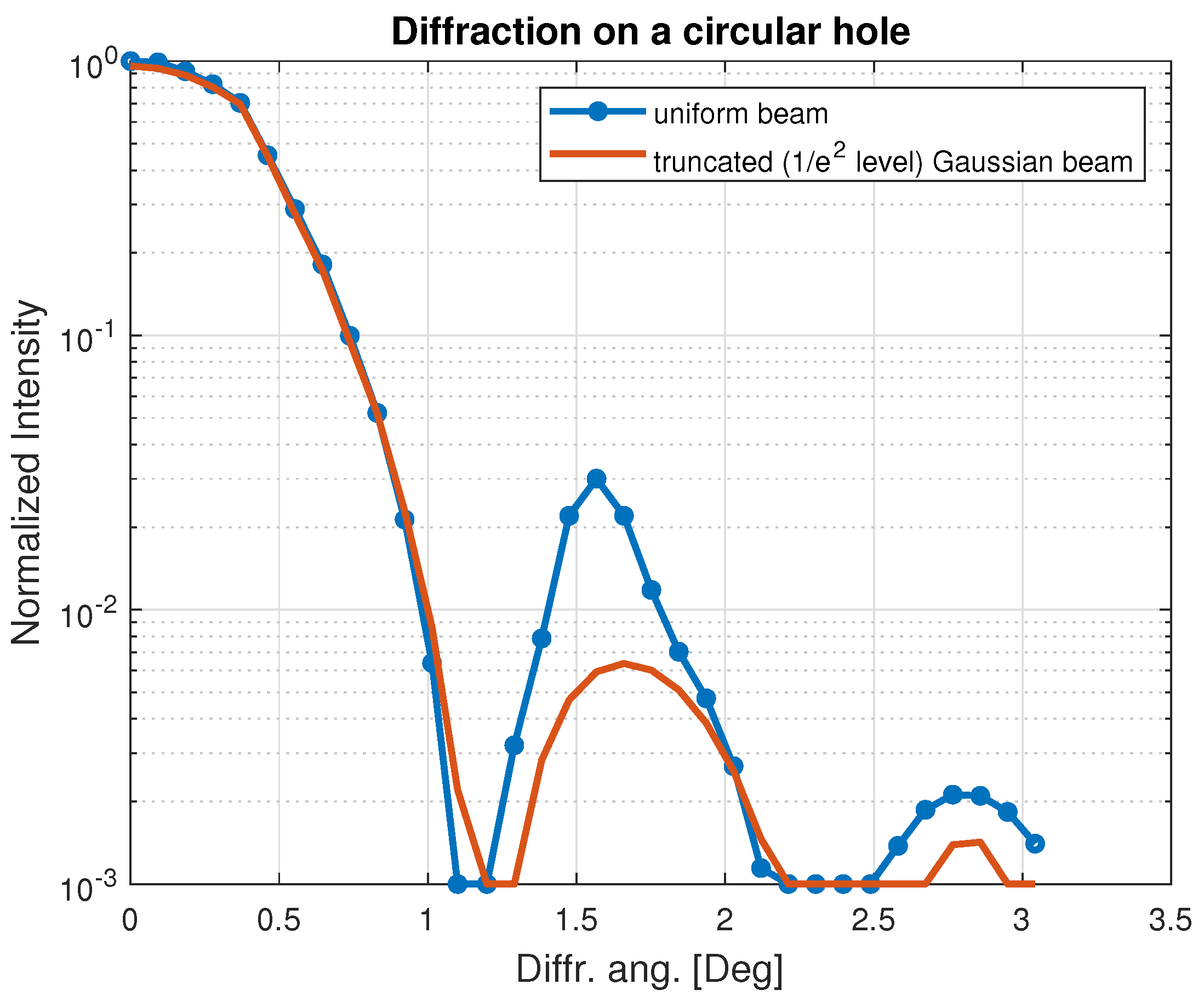
Moreover, dealing with a nano-structured facet of a light-guide and using the chosen wavelength, we often cannot minimize the size of the focal spot of the input beam. We did not provide this analysis in the previous publication, taking into consideration only the part of the beam power which hits the facet. Reducing the edge effect requires additional means. The problem is analogous to one of reducing side-lobes of a beam diffracted by a hole. This is the old problem of classical optics. One of the conventional means, resolving it for a circular hole, is in using Gaussian beams. The proper illustration given below is imported (and restored) from [8].
The graphs in this Figure 1 demonstrate that the Gaussian beam provides a concentration of diffracted energy in the main lob while reducing the energy diffracted to the side lobes. We can probe such a solution in our case as well. It means using the apodization of the whole structure. However, the simplified calculations (see Appendix B) show that:
- -
- The angular distribution of the diffracted beam occurs to be partly smoothed by the pins’ parabolic shape, but not by an edge apodization.
- -
- A large enough critical angle for total internal reflection (TIR) in our case (light-guide material) allows collecting all forth-scattering peaks. Thus, the edge effect is not significant at all.
- -
- Apodization, in turn, leads to redistribution of the beam energy in favor of the side lobes. This effect will increase the losses by those lobes, for which the TIR condition will be broken.
Summarizing, we state that the considered structures do not require any correction for diminishing the edge effects.
Recall that the additional requirement complicated our general task (as in the previous stage too). We took it upon ourselves to meet the above criteria for a light-guide, which a high optical contrast with its surroundings. In our study, we deal with Si light-guide, which is transparent in our wavelength range and provides the transmission about 82% for a wide enough polished surface.
We note that all the results below were obtained by numerical calculations fulfilled by the commercial simulator “Lumerical”, which uses the FDTD method. The numerical simulations were performed for the given size facet. “Lumerical” solves the Maxwell equations numerically under the boundary conditions determined by the facet and the light-guide itself. The multiple scattering is taken into account automatically. Thus, we dependably estimated the advantages of pins smoothing.
2. Parabolic Smoothing
As discussed in the previous section, the multiple scattering contribution forces us to modify the conical shape of the unit cells obtained by solving the variational reflection minimization problem. For a discussion of the multiple scattering effect contribution, see, for example, Simonetti and Garnett in [9,10,11]. Our previous publication shows that an effective modification is using a paraboloid shape instead of the proper cone. Here, we test the efficiency of smoothing pyramidal unit-cells.
The advantage of parabolic smoothing is obtaining the surface smooth also with respect to its derivatives (a higher order of smoothness).
It is necessary to note that this recommendation cannot be accepted as the general one, equally efficient for any shape of the cross-section. Numerical tests are required for any specific configuration of the cross-section. However, the main conclusion can be made: smoothing leads to a better flatness of transmission characteristic as the function of the wavelength. It is already seen in Figure 5 of [1] (in a sense, it is appropriate to point to Chebyshev-type fillers as an analogy (see, e.g., [12])). The smoothing efficiency is tested here for round, square, rectangular, and hexagonal basis of unit-cells (pins).
3. Height Randomization of Pins in Conic-Parabolic Structure
It is well known (see, e.g., [3]) that one can obtain almost zero reflection for a single spectral line. Such a result is achieved without any randomization. However, any widening of the required spectral range affects the possible minimal reflection while understanding it in terms of the mean value. However, this is not yet the well-defined formulation of the goal. For a trustful evaluation of the role of randomization, one has to proceed from an explicit criterion. In the present discussion, we accept the following one:
- -
- maximization of the mean value of transmission in the required spectral interval (); and
- -
- minimization of the standard deviation of transmission (defined as usually: ).
Previous discussions on the effect of randomization can be found, e.g., in [4,5]. However, first, we have to emphasize some significant aspects.
- (a)
- The true effect of randomization can only be seen for a large enough facet. Any statistics is valid only for a large number of elements (unit cells).
- (b)
- The optimal structure of the whole facet has to take into account the profile of the illuminating beam.
The illumination scheme in a virtual experiment (and, namely, this illumination—of the Gaussian shape—is taken into account in our numerical calculations) is depicted in Figure 2. In our calculations, we use our laboratory fiber laser providing 7 m diameter of the focal point and of divergences after the focus. The Si light-guide has the aperture of 20 × 1.5 m.
We see immediately that this geometry does not respond to the requirements mentioned above. Therefore, the results presented below are not the best which could be obtained with the same pin-structure in the ideal conditions. In the previous publication, we discussed the possible effect of randomization of pins’ heights in the structure (see Figure 3). Here, we present numerical analysis results, which show that the conclusions about the efficiency of the randomization are not straightforward.
First, we recall the results concerning the effect of the height of conic, parabolic smoothed pins on the transmittance of the facet.
Turn to the graphs depicting the transmission efficiency of the facets studded by parabolic pins (the small dimension of its aperture is 20 × 3). In the numerical calculations (here and after), we define transmission of the facet on a light-guide input (output) surface as the forward scattering in the range of angles required for the light-guide.
Here, the value of the standard deviation indicates the randomization level.
We calculated the parameters chosen as the criterion:
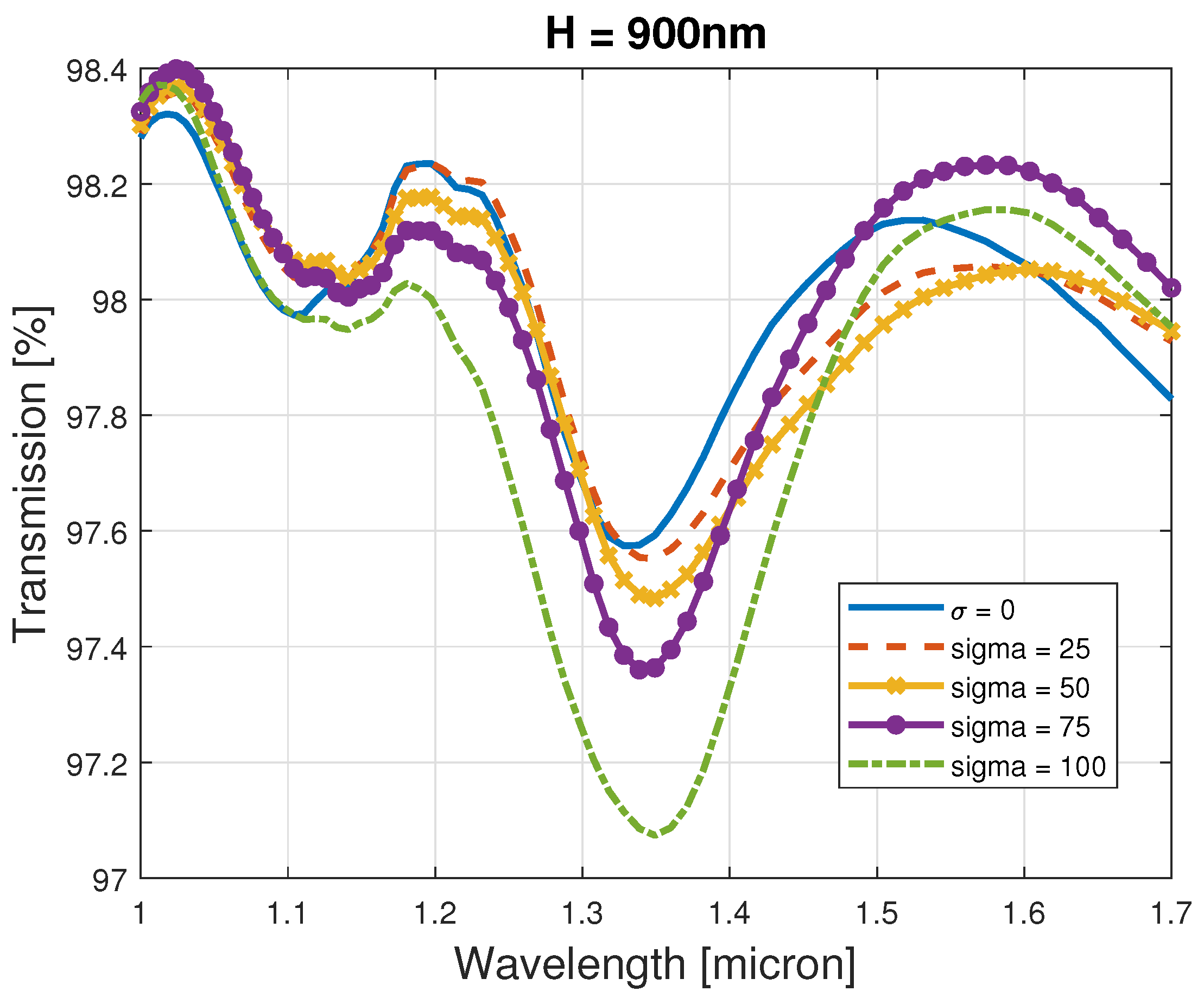
For nonrandom structure (), the mean transmission is and the standard deviation of transmission is (). The results are given in detail in Table 1.
We see (Figure 4) that, for the given facet, it is not easy to conclude which one of the tested randomized structures is the best. The conclusion here is: for small apertures, randomization is not efficient. It is not a surprising result; it is already mentioned above.
To support this statement, we present below additional graphs (Figure 5, Figure 6, Figure 7, Figure 8 and Figure 9) and the following Table 2, Table 3, Table 4, Table 5 and Table 6 for randomized paraboloids with different standard deviations.
.
However, some conclusions can still be made: a larger requires a larger mean value of H.
It is interesting, but the actual technology restricts a possible value of the height. For example, while using Focused Ion Beam (FIB), we face the restriction as , where is the base diameter of the paraboloid. For laboratory tests, one often chooses the available equipment. Today, we can use also the laser engraving [13,14], lithography [15], and the most accurate nano-scribe technology [16]. The last one is perhaps the most expensive and hardly available for Si. However, it is possibly the single one allowing to obtain the difficult to locate pins, as we require. As we estimate, lithography is more attractive for series manufacturing and hardly useful for samples gradually varying in depth. The laser methods’ advantages or disadvantages depend on the sample material and scale and the achievable diameter of the focal spot.) This fact puts an additional restriction on the ability and efficiency of randomization. Moreover, based on our results, we can state that randomization does not improve the transmission function’s flatness.
4. Pyramidal Structures
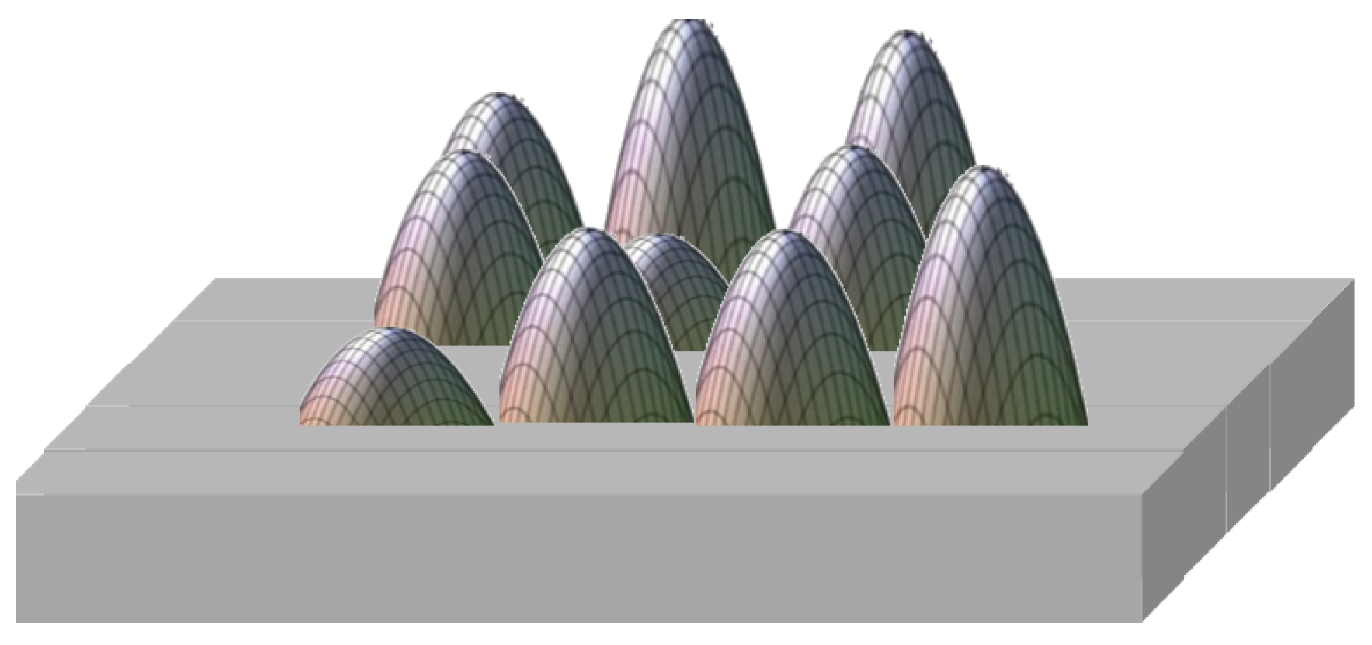
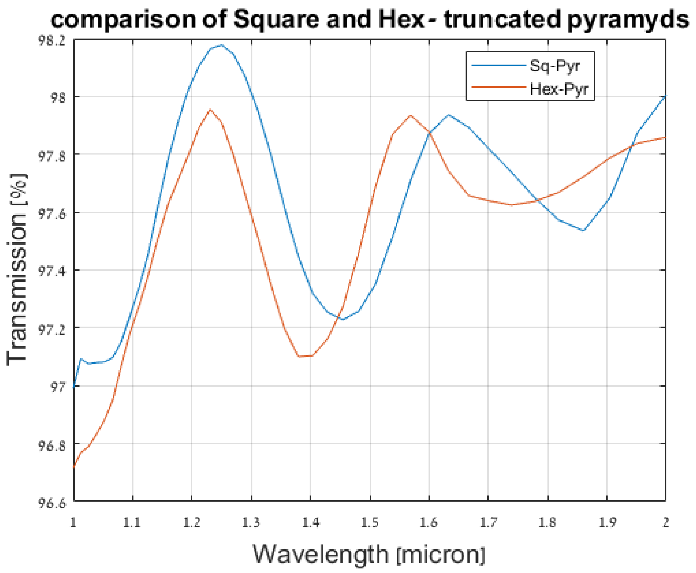
As discussed above, pyramidal pins potentially promise an increase in transparency due to improved fill-factor. We obtain the best fill-factor for rectangular (square, for specific facet shapes) pyramids. The illustrations of the structure, based on square and hexagonal pyramids, are given in Figure 10.
The square and hexagonal shapes differ not only by the fill-factor but also by the scattering shape. Therefore, the final conclusion can be made only after accurate numerical calculations.
The pyramidal structures were considered in different studies (e.g., [17,18]); however, only as a case and without general conclusions. Here, we generalize the analysis that allows us to provide confident recommendations. When using rectangular facets, the main evident advantages of pyramidal structures are in increasing the fill factor. A facet composed of hexagonal pyramids retains a free area at the edges anyway. Our illustrations in Figure 10 show this fact in the evident form. For the correct comparison of the two structures’ efficiency, we have to take their sizes more or less equivalent (we chose the criterion as equality of their heights and their bottom and upper areas). For example, where the height of the pyramid is nm, the side of the bottom base of the square-based pyramid is nm, and the upper square is nm, and the same areas for the hexagon pyramids. The results are shown in Figure 11.
For easier comparison, we give below the mean values and standard deviations of transmission for the tested pyramids (in natural units). The results given in detail in the Table 7.
The results are slightly different, but the square pyramid is still preferred. Therefore, further, we consider only this type of pyramids.
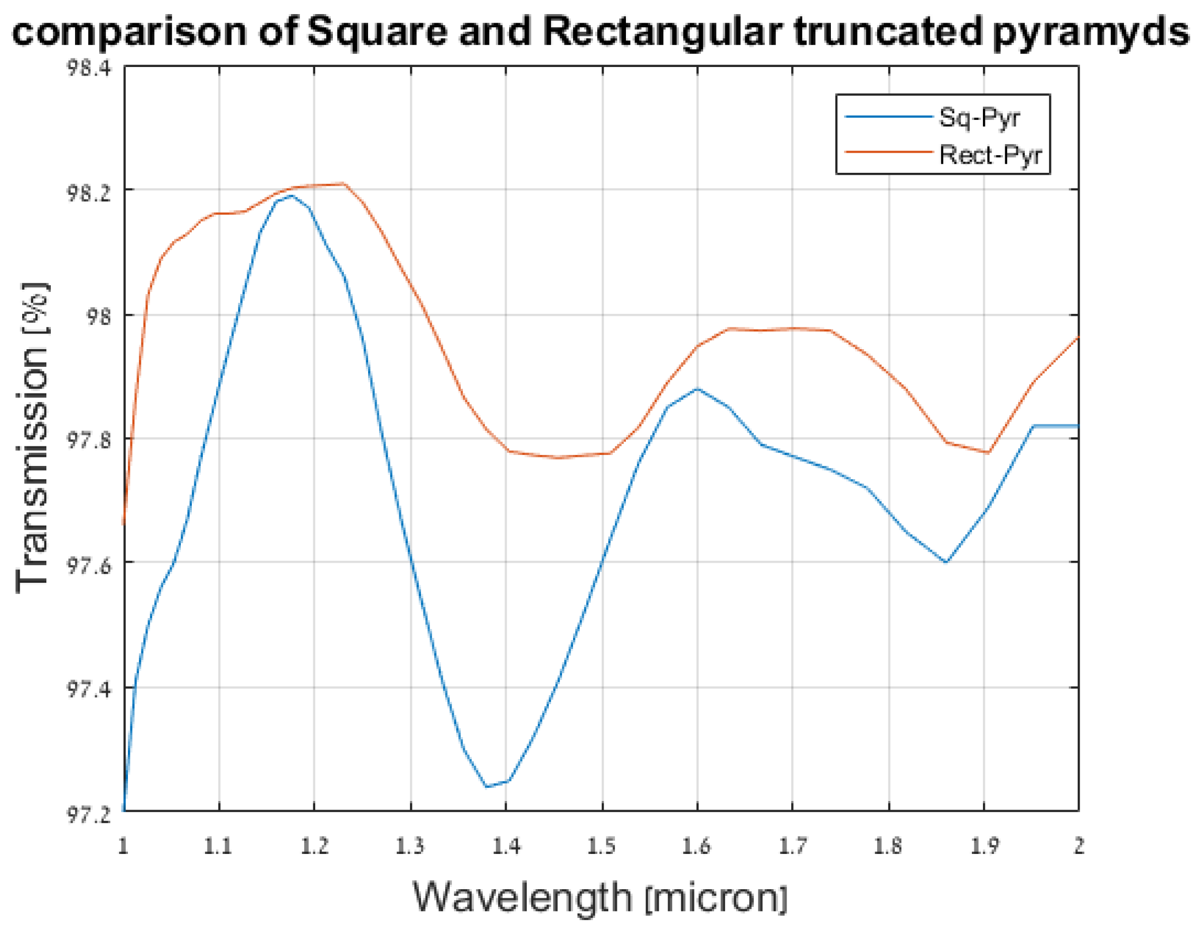
Adopting a bottom of the pyramidal uni-cell of rectangular and not a square shape, one can achieve the fill-factor as 1. The results of the proper test are demonstrated in Figure 12.
In terms of area, the rectangular pyramids’ base was taken equal to the bottom of the square one. However, the aspect ratio was taken to be appropriate to obtain a fill factor of 1. The results show the advantage of a regular rectangular structure. The mean transmission reaches the level as 99%.
However, the size of the rectangular base is determined by the shape of the facet; thus, it must be a specific choice every time. In order not to be limited to a particular form of the facet, in the following, we analyze mainly the square bases of the pyramids. Only one specific case was taken to assess the maximum fill factor’s influence, and it shows its importance. For this particular facet, the improving factor for the mean transmission is , but the improvement of the standard deviation is significant (Figure 13).
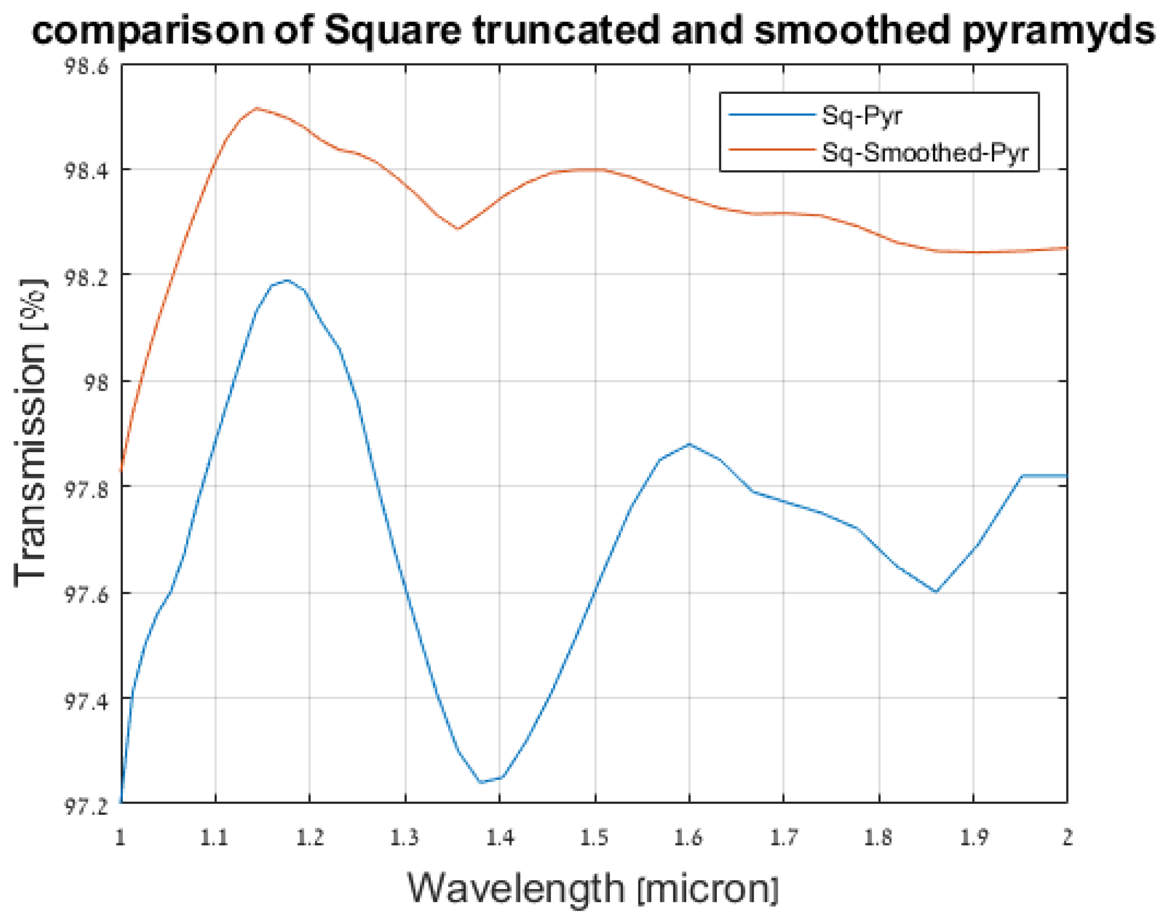
4.1. Truncated and Smoothed Rectangular Pyramids
Recall, first that, dealing with cones ([1]), we obtained the best results for those with the bottom diameter nm. Therefore, in further analysis, we accept the pyramids with a similar bottom area. As previously, we expect some improvement in the transmission by smoothing the pyramids. It seems natural enough to expect an impoverished scattering angular spectrum for smoother scatterers. The height of the parabolic cap (smoothing) is taken as 200 nm. The results of both cases are given in figure. The height of the parabolic cap (smoothing) is taken as 200 nm. The results of both cases are given in Figure 13.
The smoothed surface provides an apparent improvement. The mean value of transmission achieved a value of 0.983, with a standard deviation of about 0.0014 (i.e., the smoothing of pins significantly improves the flatness). Smoothing of rectangular pyramids is more problematic; however, recalling our previous estimation, one can hope to get the mean value of transmission about 0.987. In the next short section, we show the results of randomizing the pins’ height on the facet. Another possibility, modification of the edge pins to smooth the edge effect, is discussed in Appendix B.
4.2. Randomization of Height of the Unit-Cells in Smoothed Pyramidal Structures
In this section, we try the effect of height randomization for the pyramidal structure. The results for different are depicted in Figure 14.
As is seen, the randomization of pin height in the pyramidal structure works even worse than in the conical structure. Moreover, it can give even a negative effect. These results are not so surprising. In the literature, we can find an intensive discussion on the pros and cons of randomization (see, e.g., [4]). Such results of randomization for conic structures are discussed above. Thus, we can conclude that any randomization can provide an effect (positive or negative) only for large enough facets.
A numerical analysis of a large facet is a bulky task. A gradient index model for large surfaces (described in [1]) is to be accurate enough in their central area (where edge effects do not contribute). The model works in a range of wavelengths matched to it. Moreover, in this range, we do not indicate an essential dependence of the reflectance (transmittance) on the wavelength. Therefore, the need in randomization looks doubtful (see Appendix B in the present work).
5. The Simple Way for Comparing Calculation and Experimental Results
Underline from the very beginning, the numerical calculation of the reflection and transmission for the wave passed through a light-guide is a very bulky problem. With this, any laboratory measurements (of reflection or transmission characteristics) deal just with a wave transmitted through a light-guide once or several times. However, there is a workaround, which allows for significantly simplifying the necessary calculations.
First, we consider a plane wave propagating through space (filled by a medium with the refractive index n) bounded by flat parallel (normal to the direction of wave propagation) boundaries. Call it a slab (despite its infinite side boundaries). Let air be its ambient medium.
Let r and t be the reflectance and transmittance, respectively, of each boundary facet and R and T the reflectance and transmittance of the whole slab. Designate the thickness of this slab as D. Let also the input wave amplitude be 1.
For the reflection from the slab (in the scalar form), we have (see, e.g., [19])
where .
In turn, for the transmission though this slab, we write
From this equations, we get the simple relation
Principally, measuring R and T, one can estimate the reflectance r of the facet and compare it with the calculated value. However, this task’s single problem is the accurate measurement of D (of the order as ).
On the other hand, we get similar equations while dealing not with the infinite plane but a light-guide mode (for a single-mode light-guide or the proper superposition of modes for a multi-mode one) with a single difference. Namely, the factor has to be replaced by another one (designated as ).
Thus, the factor is the single obstacle for simple experimental testing of our mathematical model.
6. Discussion and Conclusions
This study is the continuation of the previous one [1], where we developed the semi-analytic formalism for calculating the parameters of a meta-surface made from a high-index dielectric material, similar to that used for the light-guide. Our analysis demonstrated the transparency effect also to high optical index optical light-guides (Si). Basing on the previous results, we analyzed more cumbersome structures and estimated maximal transmission while using structural surfaces (facets). We considered only those types of engraving which can be fabricated, therefore omitting shapes which can be defined by polynomial functions of higher than 2 (or even more complicated). In addition, we restricted our analysis by the height of the unit cells achievable for FIB technology, i.e., .
The pyramids were introduced since they satisfy our theoretical predictions and fill rectangular facets more effectively (even achieving the total fill). Despite its more complex scattering side surface (a ribbing one), numerical calculations demonstrate an improvement compared to cones. Note that hexagonal base pyramids occur less effectively than the rectangular ones. Again, the base size is determined by the required spectral range and also by the fill-factor. The hexagonal base leaves a certain unfilled edge anyway.
Smoothing the top has an essential effect for improving the transmission. In turn, the optimally tailored rectangular base improves the transmission additionally.
We showed that this configuration allows achieving 0.987 transmission level in 1–2-micron wavelength range with the flatness of about 0.2%. We note that flatness is a crucial characteristic, limited together with the mean value of the minimal transmission in the required spectral band. On the contrary, randomizing the pins’ heights does not provide a remarkable effect, and the pyramidal structure worsens the transmission. This negative effect can be explained by the small size and specific aspect ratio of the facet.
The surface smallness does not result in transmission degradation determined by the edge effects but restricts the engraving’s positive impact.
Here, and in the previous work, we provide a systematic analysis of the structures, justified theoretically in the single-scattering approximation. Improvements in transmission (reflection) and especially flatness characteristics were achieved. It is worth highlight that the effect was obtained not so much due to the shape of the pins (conical or pyramidal), but due to their smoothing and increasing the fill-factor. The shape smoothing allows for adopting the structures to the actual multi-scattering case. Moreover, the smoothed pins are easily realizable. The approach elaborated in our study is equally useful for other shapes and sizes of facets. We can claim that we obtained the best possible result for realizable facets for the considered rectangular profile with the given size.
Author Contributions
I.G. developed the theoretical aspects and conducted the research. Y.G. built numerical model and ran the simulations. K.H. and Y.T. ran the simulations for different pyramidal structure and conceptualized the idea of using rectangular pins. All authors have read and agreed to the published version of the manuscript.
Funding
This research received no external funding.
Conflicts of Interest
The authors declare no conflict of interest.
Appendix A. Gradient Index Model for Indefinite Surfaces
Here, we turn again to the gradient index model to estimate the result (reflectance and transmittance), which can be accepted as the ideal one, and compare it with those obtained for our structures. In [1], we analyzed this model for the initial choice of the best shape of the pins. However, on the one hand, it is difficult to evaluate directly the integrals appearing there. On the other hand, a computer analysis of multilayered structures (M sub-layers) is fraught with numerical errors growing with adding new layers. In our case, the number of layers tends to infinity (). For these reasons, we undertake the analysis of the matrix expression describing an M-layered structure.
Let H be the total depth of the gradient index layer. Take all layers to be of the same thickness . In the previous publication, we obtained that the best structure for minimal reflectance (if only single scattering is taken into account) is an engraving involving pins (or indentations) with a constant slope. In such a structure, and with compact localization of pins, the mean refraction index of an effective jth sub-layer is
Here, we accept that the medium in front of the light-guide possesses the refractive index , and the medium behind the light-guide possesses the refractive index . With this, if k is the wave factor in vacuum, the effective wave factor in jth sub-layer is .
In the following, we use the matrix-formalism (see, e.g., [19]).
We write our basic equation as
The transfer matrix T is defined as
where is the product of P-matrices describing the sub-layers.
and
Thus, taking into account our agreement concerning ambient media, we have finally for the transfer matrix
Now, our equations for scattered (reflected) and transmitted fields are obtained form
Taking into account that, with a large M, we have , we are able to make the necessary estimations. Actually, for estimating the fields, we only need and .
First,
It is easy to notice the following:
where denotes , for the structure with M layers. A similar estimation can be made also for .
However, these relations are not detailed enough for evaluating the difference between and . The main obstacle here is in necessity to multiply finally the matrix P on , while calculating the matrix T.
However, since our final purpose is in estimating the structure of T, only this is necessary.
To get the proper relation, the equation for P is modified in the following way (called here the C-trick).
Introduce the matrices
and
These matrices are inverse to each other. Therefore, we can rewrite Equation (A4) as
Here, we take . Designate further
and then
In this representation, we obtain T in a form that is simple for estimation.
For the final estimate, we perform some algebraic transformations. First,
In other words, the difference in the refractive index of neighbour layers is a value of order . Indeed,
Now, matrix T obtains a structure.
Note that, since , after multiplication of these matrices, the relation has the accuracy of . With this, we also have .
It is easy to see that the resultant T matrix keeps a similar form. As the last step, we obtain
Recall that, with , we have ; thus, taking into account Equation (A5), we obtain that T turns into the unit matrix. For its elements determining the reflected and transmitted waves, we have
This is the result we desired. In the field terms, the structure described as the gradient index layer provides its absolute transparency:
and
It is interesting to underline that the wavelength does not appear in our final equation in the explicit form. The physical reasons restrict the range by conditions adopting the model. In the real calculations, the taken wavelength determines the convergence of our infinite products.
Appendix B. The Edges Effect
The restriction of the light-guide aperture inserts inevitable degradation. Generally, they appear as additional scattering peaks only partly transmitted into the cardinal direction (into the light-guide). To analyze the effect approximately in a simple way, we use here the Fourier analysis of the facet structure (this approach is widely known, see, e.g., [20,21]). By this technique, we can probe also the apodization effect (for the use of FFT in actual calculations, see [22]).
For the rectangular form of the aperture in our cases, we can restrict ourselves by analyzing its linear cross-section, specifically the short one, represented by the Fourier image.
Take two examples:
- -
- A cross-section of the structure containing three pyramidal pins
- -
- A cross-section of the structure containing five paraboloidal pins
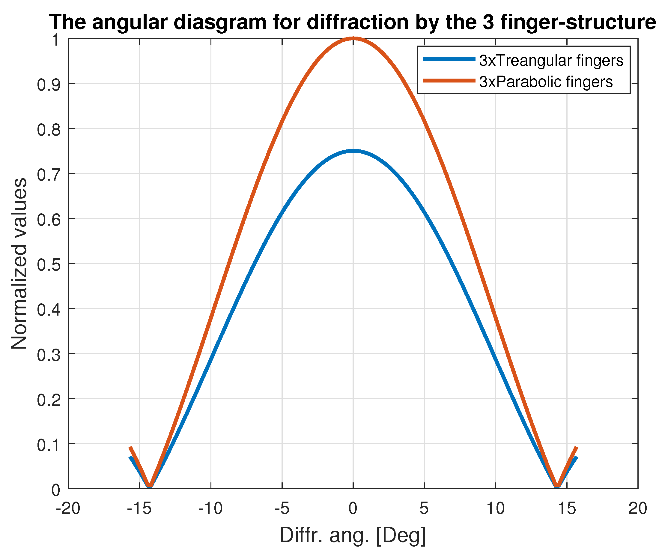
Figure A1 presents in comparison the angular diagrams (the angles are calculated in the medium of the light-guide—Si) for these two cases.
Figure A1.
Comparison of the angular diagram (in the proper cross-section) of the forward scattering for the facet containing three pins at the narrow side: blue line: pyramidal pins; brown line: paraboloid pins.
Figure A1.
Comparison of the angular diagram (in the proper cross-section) of the forward scattering for the facet containing three pins at the narrow side: blue line: pyramidal pins; brown line: paraboloid pins.

One can make the conclusion already from this graph:
- Indeed, the parabolic shape of the pins provide concentration of the beam energy in the global lobe.
- However, actually, this does not matter. For a Si-based light-guide (this is just our case), the critical angle for TIR on is . Thus, in our case, the whole diffracted beam inserts in the light-guide without losses.
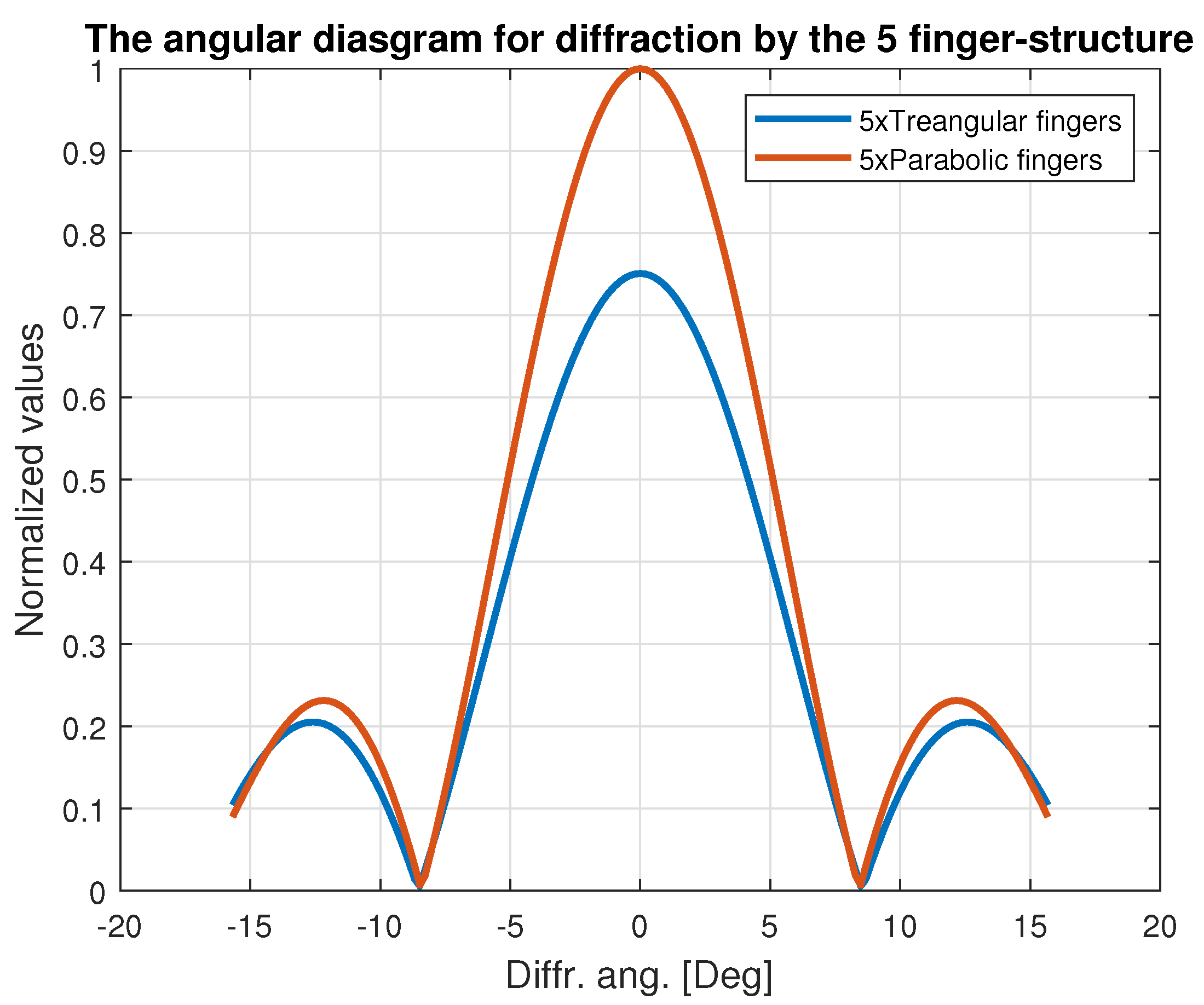
Try now a structure containing five pins across the narrow side. The angular diagram is shown in Figure A2. Now, the side-lobes do contribute to the transmitted energy and still satisfy to the TIR criterion. Again, the parabolic pin shape provides a higher concentration of the beam energy in the main lobe, but it is not critical.
Figure A2.
Comparison of the angular diagram (in the proper cross-section) of the forward scattering for the facet containing five pins at the narrow side: blue line: pyramidal pins; brown line: paraboloid pins.
Figure A2.
Comparison of the angular diagram (in the proper cross-section) of the forward scattering for the facet containing five pins at the narrow side: blue line: pyramidal pins; brown line: paraboloid pins.

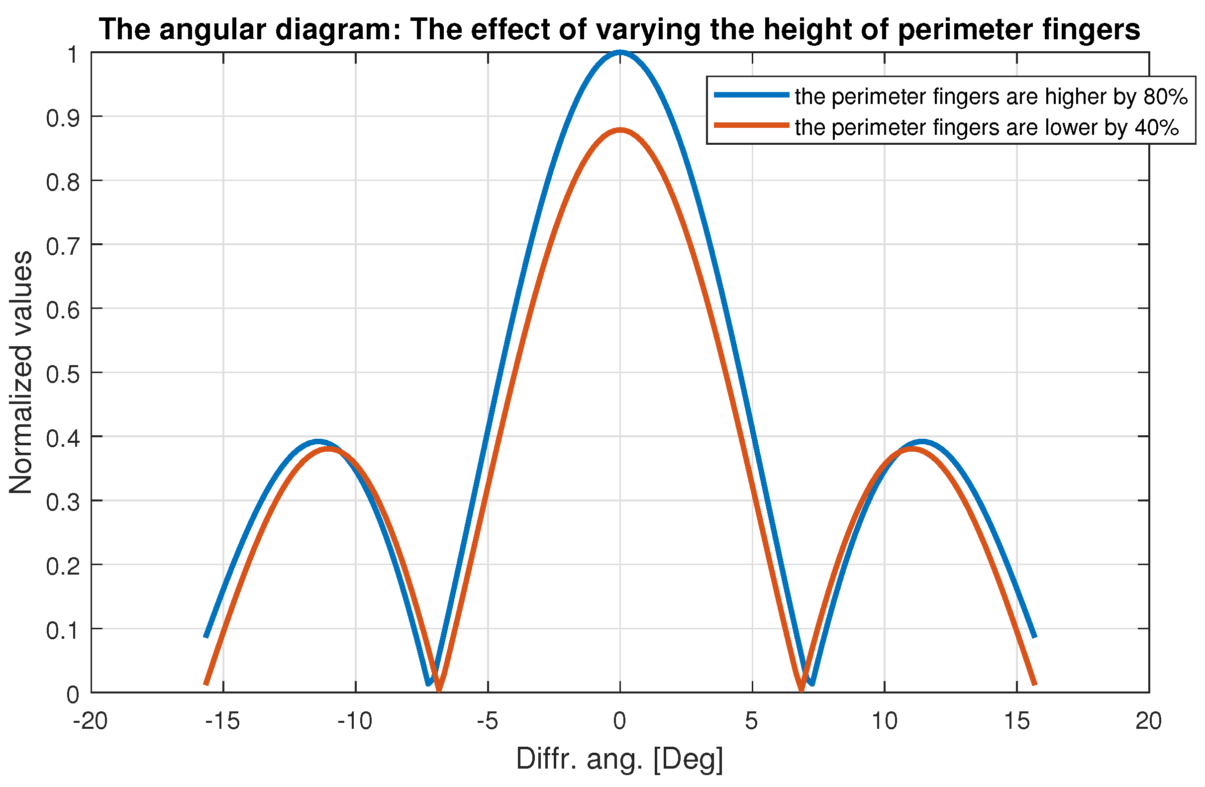
Despite the fact that the previous examples did not indicate any necessity of apodization, we illustrate the effect below basing on the structure involving five triangular pins. We take for comparison two modifications (See in Figure A3):
- (1)
- The perimeter pins are taken as 1.8 of the basic ones.
- (2)
- The perimeter pins are taken as 0.6 of the basic ones.
Figure A3.
Comparison of the angular diagram (in the proper cross-section) of the forward scattering for the facet containing five pins at the narrow side: blue line: higher perimeter pins; brown line: lower perimeter pins.
Figure A3.
Comparison of the angular diagram (in the proper cross-section) of the forward scattering for the facet containing five pins at the narrow side: blue line: higher perimeter pins; brown line: lower perimeter pins.

The results show that apodization does not demonstrate any desired effect. Moreover, the side lobes contain more portion of energy than in the previous tests. This can lead to additional losses for some modified structures.
References
- Karabchevsky, A.; Falek, E.; Greenberg, Y.; Elman, M.; Keren, Y.; Gurwich, I. Broadband transparency with all-dielectric metasurfaces engraved on waveguide facets: Effect of inverted and extruded features based on Babinet’s principle. Nanoscale Adv. 2020, 2, 2977–2985. [Google Scholar] [CrossRef]
- Markel, V.A. Introduction to the Maxwell Garnett approximation: Tutorial. JOSA A 2016, 33, 1244–1256. [Google Scholar] [CrossRef] [PubMed] [Green Version]
- Deinega, A.; Valuev, I.; Potapkin, B.; Lozovik, Y. Minimizing light reflection from dielectric textured surfaces. JOSA A 2011, 28, 770–777. [Google Scholar] [CrossRef] [PubMed] [Green Version]
- Berginc, G. Periodic or random nanostructures for light scattering control. Appl. Phys. A 2016, 122, 318. [Google Scholar] [CrossRef]
- Siddique, R.H.; Gomard, G.; Hölscher, H. The role of random nanostructures for the omnidirectional anti-reflection properties of the glasswing butterfly. Nat. Commun. 2015, 6, 6909. [Google Scholar] [CrossRef]
- Shi, Y.; Wang, X.; Yang, F. Disorder Improves Light Absorption in thin film silicon solar cells with hybrid light trapping structure. Int. J. Opt. 2016, 2016, 9371608. [Google Scholar] [CrossRef] [Green Version]
- Sanchez-Gil, J.; Nieto-Vesperinas, M. Light scattering from random rough dielectric surfaces. JOSA A 1991, 8, 1270–1286. [Google Scholar] [CrossRef] [Green Version]
- Rosen, J.H. Diffraction Patterns Produced by Focused Laser Beams; Technical Report; Rand Corp: Santa Monica, CA, USA, 1972. [Google Scholar]
- Simonetti, F.; Fleming, M.; Marengo, E.A. Illustration of the role of multiple scattering in subwavelength imaging from far-field measurements. JOSA A 2008, 25, 292–303. [Google Scholar] [CrossRef] [PubMed] [Green Version]
- Garnett, E.; Yang, P. Light trapping in silicon nanowire solar cells. Nano Lett. 2010, 10, 1082–1087. [Google Scholar] [CrossRef] [PubMed]
- Simonetti, F. Multiple scattering: The key to unravel the subwavelength world from the far-field pattern of a scattered wave. Phys. Rev. E 2006, 73, 036619. [Google Scholar] [CrossRef] [PubMed]
- Benvenuti, L.; Farina, L. The design of fiber-optic filters. J. Light. Technol. 2001, 19, 1366–1375. [Google Scholar] [CrossRef]
- Balaji, V.; Castro, K.; Folch, A. A Laser-Engraving Technique for Portable Micropneumatic Oscillators. Micromachines 2018, 9, 426. [Google Scholar] [CrossRef] [PubMed] [Green Version]
- Salazar, C.T.; Azcárate, M.L.; Rinaldi, C.A. Nanostructuring of material surfaces by laser ablation. In Radiation Effects in Materials; IntechOpen: Rijeka, Croatia, 2016; p. 431. [Google Scholar]
- Lin, S.; Hammood, M.; Yun, H.; Luan, E.; Jaeger, N.A.; Chrostowski, L. Computational lithography for silicon photonics design. IEEE J. Sel. Top. Quantum Electron. 2019, 26, 1–8. [Google Scholar] [CrossRef]
- Niesler, F.; Tanguy, Y. 3D Printers for the Fabrication of Micro-Optical Elements: Disruptive technology enables the way for unprecedented applications. Opt. Photonik 2016, 11, 44–47. [Google Scholar] [CrossRef]
- Raguin, D.H.; Morris, G.M. Antireflection structured surfaces for the infrared spectral region. Appl. Opt. 1993, 32, 1154–1167. [Google Scholar] [CrossRef] [PubMed]
- Southwell, W.H. Pyramid-array surface-relief structures producing antireflection index matching on optical surfaces. JOSA A 1991, 8, 549–553. [Google Scholar] [CrossRef]
- Born, M.; Wolf, E. Principles of Optics: Electromagnetic Theory of Propagation, Interference and Diffraction of Light; Elsevier: Amsterdam, The Netherlands, 2013. [Google Scholar]
- Novotny, L.; Hecht, B. Principles of Nano-Optics; Cambridge University Press: Cambridge, UK, 2012. [Google Scholar]
- Phillips, T. X-ray Crystallography and the Fourier Transform. American Mathematical Society. 2017. Available online: http://www.ams.org/samplings/feature-column/fc-2011-10 (accessed on 1 April 2020).
- Mas, D.; Garcia, J.; Ferreira, C.; Bernardo, L.M.; Marinho, F. Fast algorithms for free-space diffraction patterns calculation. Opt. Commun. 1999, 164, 233–245. [Google Scholar] [CrossRef]
Figure 1.
Reducing the side lobes of the beam diffracted by a circular hole by using the Gaussian shape.
Figure 1.
Reducing the side lobes of the beam diffracted by a circular hole by using the Gaussian shape.

Figure 2.
Illumination of a facet by a laser beam.

Figure 3.
Randomized paraboloids structure.

Figure 4.
Transmission for paraboloid facet with the average height nm and different levels of randomization.
Figure 4.
Transmission for paraboloid facet with the average height nm and different levels of randomization.

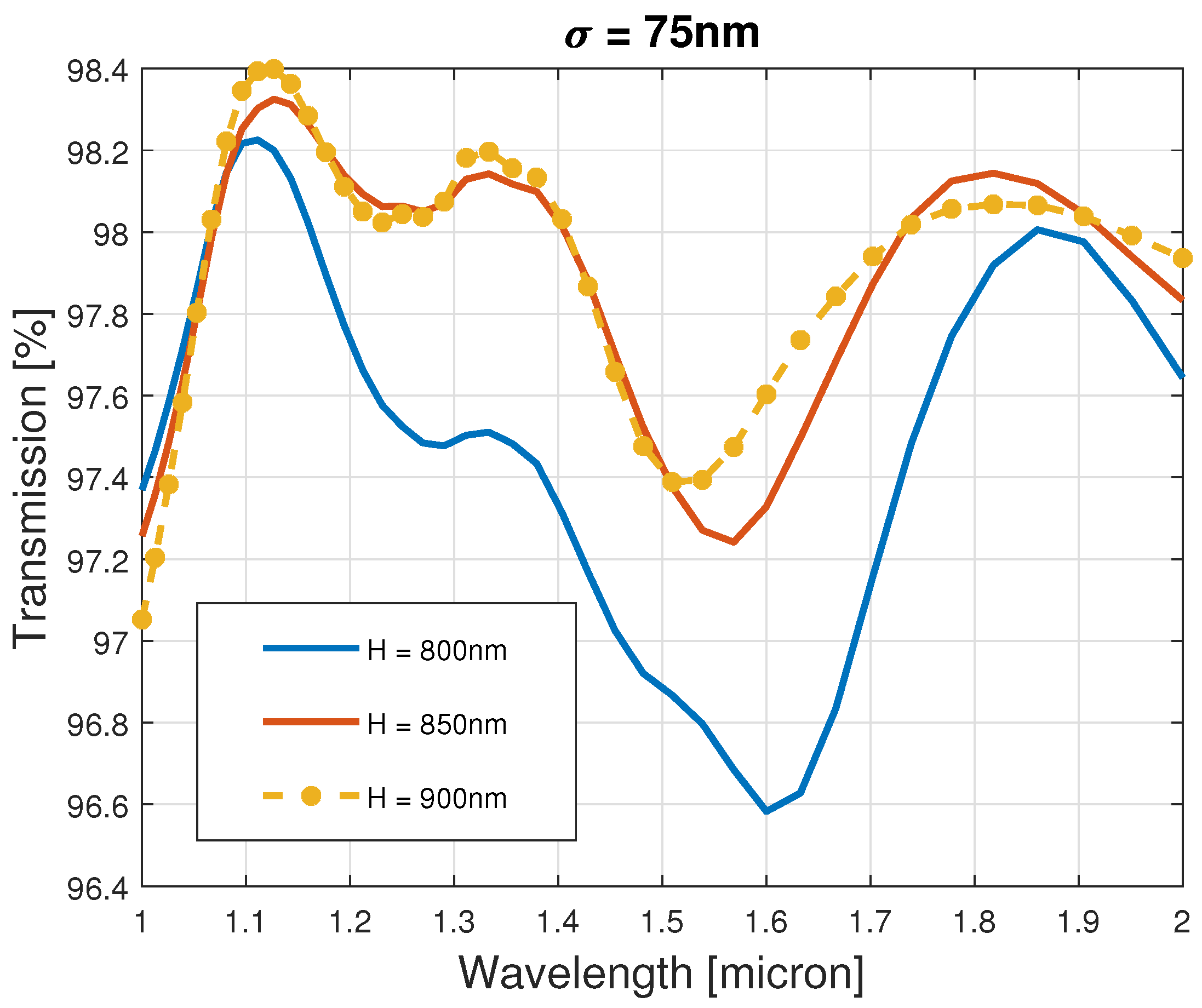
Figure 5.
Transmissions for paraboloid facets without randomization.

Figure 6.
Transmissions for paraboloid facets with nm.

Figure 7.
Transmissions for paraboloid facets with nm.

Figure 8.
Transmissions for paraboloid facets with nm.

Figure 9.
Transmissions for paraboloid facets with nm.

Figure 10.
Truncated square and hex pyramidal structures: (a) square truncated pyramids; and (b) hex truncated pyramids.
Figure 10.
Truncated square and hex pyramidal structures: (a) square truncated pyramids; and (b) hex truncated pyramids.

Figure 11.
Comparison of transmission of truncated squared and hex pyramids.

Figure 12.
Comparison of transmission of truncated squared and rectangular pyramids

Figure 13.
Comparison of transmission of truncated square and smoothed pyramids.

Figure 14.
Comparison of transmission of smoothed square pyramids with different randomization of the height.
Figure 14.
Comparison of transmission of smoothed square pyramids with different randomization of the height.


Table 1.
For Figure 4.
Table 1.
For Figure 4.
| 25 nm | 0.98246 | 0.003009 |
| 50 nm | 0.98254 | 0.003011 |
| 75 nm | 0.98217 | 0.003307 |
| 100 nm | 0.98184 | 0.003375 |
Table 2.
For Figure 5—Without randomization:
Table 2.
For Figure 5—Without randomization:
| 800 nm | 0.9825 | 0.002925 |
| 850 nm | 0.982369 | 0.00296 |
| 900 nm | 0.9818 | 0.003 |
Table 3.
For Figure 6; = 25 nm.
Table 3.
For Figure 6; = 25 nm.
| 800 nm | 0.9825 | 0.002925 |
| 850 nm | 0.982369 | 0.00296 |
| 900 nm | 0.9818 | 0.003 |
Table 4.
For Figure 7; = 50 nm.
Table 4.
For Figure 7; = 50 nm.
| 800 nm | 0.9825 | 0.002925 |
| 850 nm | 0.982369 | 0.00296 |
| 900 nm | 0.9818 | 0.003 |
Table 5.
For Figure 8; = 75 nm.
Table 5.
For Figure 8; = 75 nm.
| 800 nm | 0.978258 | 0.004591 |
| 850 nm | 0.98194 | 0.003257 |
| 900 nm | 0.982171 | 0.003307 |
Table 6.
For Figure 9; = 100 nm.
Table 6.
For Figure 9; = 100 nm.
| 800 nm | 0.980236 | 0.00793 |
| 850 nm | 0.980236 | 0.004047 |
| 900 nm | 0.980179 | 0.003775 |
Table 7.
For Figure 11.
Table 7.
For Figure 11.
| PYR | Square | Hexagon |
|---|---|---|
| 0.976 | 0.0035 | |
| 0.9747 | 0.0037 |
Publisher’s Note: MDPI stays neutral with regard to jurisdictional claims in published maps and institutional affiliations. |
© 2020 by the authors. Licensee MDPI, Basel, Switzerland. This article is an open access article distributed under the terms and conditions of the Creative Commons Attribution (CC BY) license (http://creativecommons.org/licenses/by/4.0/).
Share and Cite
MDPI and ACS Style
Gurwich, I.; Greenberg, Y.; Harush, K.; Tzabari, Y. Optimising the AR Engraved Structure on Light-Guide Facets for a Wide Range of Wavelengths. Optics 2021, 2, 25-42. https://0-doi-org.brum.beds.ac.uk/10.3390/opt2010002
AMA Style
Gurwich I, Greenberg Y, Harush K, Tzabari Y. Optimising the AR Engraved Structure on Light-Guide Facets for a Wide Range of Wavelengths. Optics. 2021; 2(1):25-42. https://0-doi-org.brum.beds.ac.uk/10.3390/opt2010002
Chicago/Turabian StyleGurwich, Ioseph, Yakov Greenberg, Kobi Harush, and Yarden Tzabari. 2021. "Optimising the AR Engraved Structure on Light-Guide Facets for a Wide Range of Wavelengths" Optics 2, no. 1: 25-42. https://0-doi-org.brum.beds.ac.uk/10.3390/opt2010002