Article

Influence of Implant-Abutment Contact Surfaces and Prosthetic Screw Tightening on the Stress Concentration, Fatigue Life and Microgap Formation: A Finite Element Analysis

by
João Paulo Mendes Tribst
1,*,
Amanda Maria de Oliveira Dal Piva
2,
Laís Regiane da Silva-Concílio
1,
Pietro Ausiello
3 and
Les Kalman
4
1
Department of Dentistry, University of Taubaté (UNITAU), Taubaté 12020-270, SP, Brazil
2
Private Practice, São Paulo 06454-050, SP, Brazil
3
School of Dentistry, University of Naples Federico II, via S. Pansini 5, 80131 Naples, Italy
4
Schulich School of Medicine & Dentistry, Western University, 1151 Richmond St, London, ON N6A 3K7, Canada
*
Author to whom correspondence should be addressed.
Submission received: 24 March 2021 / Revised: 6 April 2021 / Accepted: 13 April 2021 / Published: 19 April 2021

Abstract

:
The purpose of this in silico study was to investigate the effect of abutment screw torque and implant-abutment contact surfaces on the stress generation, microgap formation and simulated fatigue life of an external hexagon connection under oblique loading. Three-dimensional numerical models of the external hexagon implant were modeled containing two different implant-abutment contact surfaces (with and without contacting the hexagon axial walls) as well as using screw torques of 20 Ncm or 30 Ncm. Following the ISO 14801, an oblique load of 100 N was applied to the prosthesis. The von Mises stress, microgap formation, safety factor and fatigue life were obtained. The stresses in the abutment screw and implant were minimally influenced by the screw torque. However, this minimal stress in the screw with a 30 Ncm torque reduced the calculated fatigue life in comparison with 20 Ncm when the external hexagon axial walls were not in contact at the implant-abutment interface. The safety factor for the implant was higher when using minimal surfaces at the abutment-interfaces; however, it compromised the screw safety factor increasing its failure probability. The higher the screw torque, the lower was the microgap formation at the implant-abutment interface. However, the calculated residual stress is proportional to the applied torque, reducing the fatigue life in the screw. This effect can be attenuated using an implant-abutment system with more contacting surfaces.

1. Introduction

Dental implants remain an important treatment option for the replacement of a missing tooth or teeth, as the success rate approximates 90% [1]. Osseointegration is a necessary requirement for the treatment modality [2], but may be jeopardized by peri-implantitis, which is a pathological cause of bone loss [3]. Peri-implantitis may result from several factors [3], including a poor implant-abutment interface, which could act as a facilitating factor in some cases.
The implant-abutment interface and peri-implantitis are correlated as bacterial plaque may accumulate at the level of the interface [3,4]. In cases where voids are present in the connection joint, they can be colonized by bacteria and form a bacterial reservoir that would subsequently contaminate the implant’s surroundings, negatively affecting the health of the peri-implant tissues [2]. The literature reports that this potential colonization of the implant–abutment micro-gap is related to multiple factors, including vertical misfit between the implant components, implant system design, applied torque and screw tightening [2,5].
A previous report, employing three-dimensional X-ray microtomography, demonstrated that different types of implant-abutment interfaces result in different levels of bacterial penetration [6]. In addition, implant systems with higher amounts of contacting surfaces, between the implant and abutment, could present a more optimal connection [6]. As the stresses generated on implants in the posterior region are higher at the implant-abutment interface [6], the masticatory forces could affect the settling of the abutment into the implant and a preload loss may occur with the incidence of occlusal loading [7,8]. Therefore, maximizing the amount of contacting surfaces at the implant-abutment interface can contribute to better stress distribution. Nevertheless, other factors can also affect the stress distribution of an implant-supported restoration, such as crown height, implant connection, load direction, cusp inclination, occlusal anatomy, and implant position [7].
When using implant-supported restorations with a two-piece system, careful attention is required in the prosthetic planning. The presence of a prosthetic screw can present an important region that concentrates stress and may lead to a biomechanical failure [9]. The presence of a prosthetic screw may also be impacted by the prosthetic connection, since the loosening of the screw has been 38% greater in external connections than in internal connections [10]. The external hexagon failure has also been attributed to the reduced resistance against the formation of microgap at the implant–abutment interface compared to the internal connection [10]. However, different microgaps will be evident when comparing different external hexagon implant systems [11]. Similar outcomes are also expected when utilizing non-original abutment connections during the prosthesis manufacturing [12], with an increase in the microgap and a reduction in the contacting surfaces between the interfaces. Therefore, the external hexagon system ratio of torque and preload is affected by the coefficient of friction, geometry, and contact surface at the implant-abutment interface [10].
It is important to note that some advantages of external connection implants still justify its use in some cases, such as the simpler prosthetic phase and increased versatility in the case of multiple implants [13]. However, the incidence of occlusal load can promote high stress magnitude in this type of connection.
To assess both stress and microgap formation, the finite element analysis can be applied as a biomechanical tool to study the implant-supported restoration [7,14]. According to the literature, there is a valid comparison between the in vitro measurements of the implant-abutment microgaps and the in-silico simulations when considering similar boundary conditions [14,15,16].
From a structural point of view, based in the stress level during loading, the implant fracture can be summarized into two basic types: (1) the immediate fracture, resulting from the application of local stresses that exceeded the yield (plastic flow) of the component’s material, or (2) the time-dependent fracture mechanism that is responsible for the vast majority of dental implant failure under fatigue [17]. With the aim to simulate the time-dependent failures, the fatigue life experiments are widely performed as simulations of the oral environment, considering the demanding cyclic loading incidence that the implant-supported restorations are subjected to.
In addition to the stress parameters and gap-formation, the details of fatigue failure of dental implants can be assessed through a computational simulation, as reported by previous studies [14]. These simulations are gaining popularity, as the randomness of the variables in fatigue testing of dental implants may affect the reliability of the in vitro tests. Therefore, probabilistic fatigue studies, using numerical simulation, should be considered [18], calculating the deterministic mechanical behavior with theoretical fatigue analysis [19].
When testing dental implants, the ISO 14801 standardizes the evaluations that compare the effect of different dental implant designs, materials, dimensions, implant-abutment connection, machining processes, surface finishes, loading and tightening conditions [20]. Consequently, the purpose of this study was to evaluate the effect of abutment screw torque and implant-abutment contact surfaces on the formation of stress, microgaps and simulated fatigue life of an external hexagon implant under oblique loading.

2. Materials and Methods

A previous reported tridimensional external hexagon model was selected [21]. The 3D file in Standard for the Exchange of Product Data (STEP) was imported and edited into the computer aided design software (Rhinoceros version 5.0 SR8, McNeel North America, Seattle, WA). The model was composed of the following structures: implant fixture (dim), fixation base, prosthetic screw, simplified abutment crown and loading piston. The dimensional parameters and geometries relation were based on the ISO 14801 for the loading test in endosseous dental implants [20]. To allow a similar number of faces between the base and the implant, a Boolean difference was applied between them, to allow a perfect fit contact region.
The final model specifications are summarized in Figure 1, according to the International Organization for Standardization (ISO) definitions. The definitions were applied to simulate the worst-case scenario with the implant’s long axis at a 30° angle in the loading direction in combination with a 20° abutment crown external angulation.
After the CAD processing, the geometries were established as volumetric solids without inconsistent and duplicated faces. The final model was then exported to the computer aided engineering (CAE) software (ANSYS 19.0, ANSYS Inc., Houston, TX, USA) and a 10% mesh control convergence test was applied determining the total number of nodes and tetrahedral elements (Figure 2). The mesh convergence was based in the linear trend of Von mises stress values according to the different mesh densities.
The final number of nodes and elements were 196,716 and 94,896, respectively. The element order was quadratic. The element type selected in the mesh division was the tetrahedral with 10 nodes (Tet-10). The mesh quality parameters were: element quality defined as 0.69 ± 0.18, aspect ratio of 1.65 ± 0.82, average maximum corner angle of 82.77° and skewness average of 0.26 ± 0.13. The inflation option was defined as a smooth transition between each contact. The rigid body behavior was standardized as dimensionally reduced controlled by the software’s automatic tool. These properties were based on previous studies and are summarized in Table 1 [22,23].
Aiming to simulate a non-linear condition, the mechanical properties required in this in silico analysis were the elastic modulus and Poisson ratio for all materials. In addition to the titanium structures, the tensile ultimate strength, ultimate yield strength and S-N curve were employed [24].
All simulated materials in the present study were assumed to be isotropic, homogenous, linear and elastic. In the contact definition, the opposing surfaces between implant-fixation base, load device-abutment, and screw-implant interfaces were considered perfectly bonded, without relative movements. The contact between the abutment and implant was set as a frictional contact with the coefficient value of 0.4 [25].
The loading and boundary conditions were performed using the finite element analysis software (Ansys). The compressive load was applied at 30 degrees from the implant axis, with magnitude of 100 N [20]. The fatigue tool was applied, based in Goodman relation theory [26,27,28], the fatigue simulation was performed considering the load repetition from 1 cycle per second (Figure 3). The constitutive law in this study followed the Robert Hooke principle for linear elastic materials. The stress–strain relation was applied, assuming the general behavior of isotropic structures.
Goodman theory is based on the Von Mises stress, used to predict yielding of materials under any loading condition [28]. The equation is as follows:
σ a = σ e [ 1 ( σ m σ u ) ]
Considering σm being the mean stress, σa being the fatigue strength in terms of stress amplitude when σm = 0 (stress amplitude), where σu is the ultimate tensile strength.
Based in the pre-processing parameters, four different conditions were simulated according to the factor: contacting surfaces (Figure 4) in the abutment-implant interface (with and without contact to the external hexagon axial walls) and screw torque (20 or 30 Ncm). To simulate the screw tightening, a new coordinate system was created in the center of the prosthetic screw neck, and the z-axis was defined as the screw long axis [29].
A bolt pre-tension was then applied with values of 20 or 30 Ncm. The von-Mises stress in the implant and in the screw, the fatigue life, the safety factor and the gap size at the implant-abutment interface, were analyzed and compared among the different preloads and contacting surface simulations.

3. Results

Figure 5 displays the model convergence check using total deformation as analysis criterion. Figure 6 displays the von-Mises stress in the implant and prosthetic screw according to the different models. Observing the stress distribution, there is a similar stress pattern between the models for the mechanical response in the exposed threads; however, the models with a higher number of contacting surfaces in the implant-abutment interface presented the highest region of stress concentration at the external hexagon.
For the prosthetic screw, the higher preload induced higher stress magnitude in the abutment screw, which was approximately 12% higher for the 30 Ncm, in comparison with the 20 Ncm for the models with minimum contacting surfaces. For the models with a more precise fit, the difference was also present; however, in a smaller proportion (1.4%). In the simulated conditions, the stress maps indicated that the stress was concentrated at the screw neck, near to the first screw thread, regardless of the evaluated model. The stress peaks for implant and screw are summarized in the Table 2.
In Figure 7, the fatigue tool was applied to display the safety factor region indicating the areas most prone to failure. The Safety Factor tool is calculated when a single load exceeds the determined failure property, which in this study, was defined as the tensile Yield strength when the implant withstands permanent deformation within its elastic limit. The Safety Factor equals the Tensile Yield strength /Max. Equivalent Stress. It is possible to observe that regardless of the model, the prone to failure region corresponds to the highest stress concentration area, as expected. Observing the absolute values in Table 3, the implant models are very similar, considering the same implant-abutment interface. For the screw, the torque as well as the number of contacting surfaces in the implant-abutment interface were able to affect the factor of safety.
In order to explain the fatigue life, the fatigue tool was used to demonstrate the calculated cycles to fail under loading repetition (Figure 8). With this present investigation, there was no calculated failure for the implant fixture regardless of the model. However, a visible difference was observed for the screw, indicating that the first thread would be the failure origin region when a minimum number of faces are present in the implant-abutment interface. The torque also affected the fatigue life, as the higher the applied torque caused the lower the number of cycles to start the failure. When a better fit interface is present, involving the external hexagon axial walls, there was no failure for the screw with 100 N of loading, regardless the torque value (Table 4).
Another tool applied in the present post-processing was the CAE contact tool. Similar to previous reports, the contact gap was calculated based in the distance between opposing nodes from a determined contact region (Figure 9). The contact region selected was the implant-abutment interface simulated with the frictional non-linear contact that allowed the nodes separation (Table 5).
Under the applied loading condition, both factors (contact surfaces and torque) affected the maximum gap value. With higher torque values, a lower gap was noticed and when more contacting surfaces were present in the implant-abutment interface, the gap was even lower.

4. Discussion

This study evaluated the effect of abutment screw torque and implant-abutment contacting surfaces relation on the formation of stress, microgaps and simulated fatigue life of an external hexagon implant under oblique loading. The use of a non-linear theoretical analysis assisted to explain the in vitro measured fatigue life and the correlation between torque and microgap formation [4,14,24,25,30].
As reported in the literature, the use of an external hexagon implant may be considered as a failure-prone prosthetic solution, due to the higher vertical misfit, stress concentration, microgap formation and increased torque loss during long-term usage [2,4,7,15,31]. Several studies have used the finite element analysis (FEA) as a method to access the biomechanical response of a unitary implant-supported restoration [4,7,15,18,19,21,25,31,32,33,34]. Despite the limitations of this investigation, the FEA may provide important information regarding simulated clinical performance, which could be of value to both clinicians and patients [9].
The stress concentration in the implant-supported restoration is directly related to design and the restorative materials. It is well known that high stress magnitude may induce restoration damage and even failure [13,33]. In this study, the proposed simulation compliance provided results in terms of stress, microgap formation, lifetime prediction and safety factor, as previously performed by other studies that have evaluated dental implants. This investigation was a simulation that was performed following the ISO 14801 for dental implants mechanical testing [16,20]. Previous studies have demonstrated effects in the strain generated in the peri-implant region [31,32,33]; however, this condition was not considered in this investigation since the model was an in vitro test representation.
Although it may seem obvious that a higher screw tightening provides a higher abutment retention, the data seems to suggest that it is not ideal, as the residual stress from the pre-load decreases the fatigue life of the system [4]. The data seems to suggest that when the implant-abutment interface is not precise, increased tightening of the screw is required to reduce the microgaps, which may shorten the fatigue life, and ultimately impact the long-term success of the prosthesis.
When comparing the mechanical responses of the models, it was possible to observe that the external hexagon platform showed a higher stress concentration, when the axial walls were in contact with the abutment. This validates, as reported in previous studies, that this region has the areas of plastic deformation when an excessive load was applied in this implant system [10,35]. Therefore, more contact between the implant and the abutment, with a higher number of surfaces contacting each other, will increase the stress in this region. However, when the stress magnitude increases in some areas, it usually decreases in other areas. In this investigation, the screw displayed a lower stress magnitude in these models, which could be considered a positive behavior, since the fracture or loosening of the screw has been reported as one of the most common mechanical failures in this prosthetic system [2,3,10,17,36]. For this reason, the use of original abutments is recommended, as it will probably result in a more accurate connection fit with the implant [12].
The preload is the tension generated in the screw and the complementary clamping force between the head of the screw and the abutment [14]. It is maintained by friction between the abutment-screw thread and the internal thread of the implant [4]. Excessive preloads increase the screw stresses that can promote plastic deformation and consequently influence long-term success.
A previous study [15] illustrated that the maximum stress of the abutment screw occurred at its neck on the distal surface and suggested that the higher stresses created by excessive preloads can accelerate the fatigue failure. This investigation supports this suggestion, corroborating with similar screw stress regions and indicating that the fatigue life will be reduced, with the failure originating in the region of higher stress.
The implant-abutment microgaps may allow the flow of the oral fluids to the inner part of the implant [6,11]. Therefore, a larger gap provides more of an opportunity of oral fluids to promote an unwanted peri-implant response, resulting in bone resorption and potential loss of osseointegration. This investigation suggests that a better fit between the implant and abutment should be preferred, minimizing the microgap formation during loading regardless the applied torque.
The literature reports that there is no clear correlation between the size of the interfacial microgap and the clinical performance of the implant [4]. This investigation suggests that the use of a more intimate contacting interface would be beneficial, improving the lifespan of the prosthesis and a reduction in the failure probability of the screw.
A previous finite element study [16] that evaluated the fatigue of dental implants, reported that for small assembly forces (lower effective bending moment) the microgap decreased with to a tighter fit, whereas the microgap is further opened when the assembly force surpasses a critical value (approximately 100 N for 30°). This investigation supports that a higher screw torque promoted a lower microgap formation; however, the microgap would still be present due to the loading.
The S-N curve (stress-number of cycles) or Wöhler curve is the graphic representation of the number of cycles that a specimen can endure before fracture, when it is subjected to a different range of cyclic loads [30]. An advantage of the theoretical model is that it allows the S-N field to be applied as the representation of an accelerated life testing, enabling a simulated projection of mechanical response long-term [30]. The fatigue prediction using the titanium alloy S-N curve presents a reliable approach, in terms of survival calculation. Titanium-based alloys are characterized by extremely low content of pores [24], which could act as defects in the initiation of a crack and possible failure.
The present study followed the ISO 14801 for implant fatigue testing with the assumed fixation cylinder to simulate peri-implant tissue resorption of 3 mm [20]. Unfortunately, this simplifies the clinical scenario in which the implant is placed in bone with variable quality [16]. Hence, there is no result that can be extracted to calculate the influence of the stress development on the surrounding bone [16,21]. The crown-implant ratio was modified, which could affect the results of this investigation by an over-simplification, by increasing the fulcrum for implant/abutment bending [36]. For each connection design, the interface was considered ideal without irregular misfit between the implant and the abutment. The torque loss by time was also not considered, simulating a condition that the pre-load remains equal from the start of the fatigue until screw failure. Further in vitro investigations are required to provide additional data and validate the limitations of a computational mathematical study [37,38,39].

5. Conclusions

Based on this limited investigation, the higher the screw torque, the lower is the microgaps formation at the implant-abutment interface. However, the calculated residual stress is proportional to the applied torque, reducing the fatigue life in the screw. This effect can be attenuated using a prosthetic system with more contacting surfaces at the implant-abutment interface.

Author Contributions

Conceptualization, J.P.M.T., A.M.d.O.D.P., P.A., and L.K.; methodology, J.P.M.T., and P.A.; investigation, J.P.M.T., A.M.d.O.D.P., L.R.d.S.-C., P.A., and L.K.; data curation, J.P.M.T. and A.M.d.O.D.P.; writing—original draft preparation, J.P.M.T., A.M.d.O.D.P., L.R.d.S.-C., and P.A.; writing—review and editing, J.P.M.T., A.M.d.O.D.P., and L.K.; visualization, J.P.M.T.; supervision, J.P.M.T., A.M.d.O.D.P., L.R.d.S.-C., P.A., and L.K. All authors have read and agreed to the published version of the manuscript.

Funding

This research received no external funding.

Institutional Review Board Statement

Not applicable.

Informed Consent Statement

Not applicable.

Data Availability Statement

The data presented in this study are available on request from the corresponding author.

Conflicts of Interest

The authors declare no conflict of interest.

References

  1. Tricio, J.; Laohapand, P.; van Steenberghe, D.; Quirynen, M.; Naert, I. Mechanical state assessment of the implant-bone continuum: A better understanding of the Periotest method. Int. J. Oral Maxillofac. Implant. 1995, 10, 43–49. [Google Scholar]
  2. Lauritano, D.; Moreo, G.; Lucchese, A.; Viganoni, C.; Limongelli, L.; Carinci, F. The Impact of Implant–Abutment Connection on Clinical Outcomes and Microbial Colonization: A Narrative Review. Materials 2020, 13, 1131. [Google Scholar] [CrossRef] [Green Version]
  3. Roccuzzo, A.; Stähli, A.; Monje, A.; Sculean, A.; Salvi, G.E. Peri-Implantitis: A Clinical Update on Prevalence and Surgical Treatment Outcomes. J. Clin. Med. 2021, 10, 1107. [Google Scholar] [CrossRef] [PubMed]
  4. He, Y.; Fok, A.; Aparicio, C.; Teng, W. Contact analysis of gap formation at dental implant-abutment interface under oblique loading: A numerical-experimental study. Clin. Implant Dent. Relat. Res. 2019, 21, 741–752. [Google Scholar] [CrossRef]
  5. Bassi, M.A.; Lopez, M.A.; Confalone, L.; Gaudio, R.M.; Lombardo, L.; Lauritano, D. A prospective evaluation of outcomes of two tapered implant systems. J. Biol. Regul. Homeost. Agents 2016, 30, 1–6. [Google Scholar]
  6. Scarano, A.; Valbonetti, L.; Degidi, M.; Pecci, R.; Piattelli, A.; de Oliveira, P.S.; Perrotti, V. Implant-Abutment Contact Surfaces and Microgap Measurements of Different Implant Connections Under 3-Dimensional X-Ray Microtomography. Implant. Dent. 2016, 25, 656–662. [Google Scholar] [CrossRef]
  7. Kim, J.H.; Noh, G.; Hong, S.J.; Lee, H. Biomechanical stress and microgap analysis of bone-level and tissue-level implant abutment structure according to the five different directions of occlusal loads. J. Adv. Prosthodont. 2020, 12, 316–321. [Google Scholar] [CrossRef] [PubMed]
  8. Kim, K.-S.; Lim, Y.-J. Axial Displacements and Removal Torque Changes of Five Different Implant-Abutment Connections under Static Vertical Loading. Materials 2020, 13, 699. [Google Scholar] [CrossRef] [PubMed] [Green Version]
  9. Tribst, J.P.M.; Dal Piva, A.M.D.O.; Lo Giudice, R.; Borges, A.L.S.; Bottino, M.A.; Epifania, E.; Ausiello, P. The Influence of Custom-Milled Framework Design for an Implant-Supported Full-Arch Fixed Dental Prosthesis: 3D-FEA Study. Int. J. Environ. Res. Public Health 2020, 17, 4040. [Google Scholar] [CrossRef] [PubMed]
  10. Vinhas, A.S.; Aroso, C.; Salazar, F.; López-Jarana, P.; Ríos-Santos, J.V.; Herrero-Climent, M. Review of the Mechanical Behavior of Different Implant–Abutment Connections. Int. J. Environ. Res. Public Health 2020, 17, 8685. [Google Scholar] [CrossRef]
  11. Bisognin, E.D.C.; Harari, N.D.; Machado, S.J.; da Silva, C.P.; de Almeida Soares, G.D.; Vidigal, G.M., Jr. Evaluation of implant-abutment microgap and bacterial leakage in five external-hex implant systems: An in vitro study. Int. J. Oral Maxillofac. Implant. 2012, 27, 346–351. [Google Scholar]
  12. Gigandet, M.; Bigolin, G.; Faoro, F.; Bürgin, W.; Brägger, U. Implants with original and non-original abutment connections. Clin. Implant Dent. Relat. Res. 2014, 16, 303–311. [Google Scholar] [CrossRef] [PubMed]
  13. Fernández-Asián, I.; Martínez-González, Á.; Torres-Lagares, D.; Serrera-Figallo, M.-Á.; Gutiérrez-Pérez, J.-L. External Connection versus Internal Connection in Dental Implantology. A Mechanical in vitro Study. Metals 2019, 9, 1106. [Google Scholar] [CrossRef] [Green Version]
  14. Lee, H.; Jo, M.; Noh, G. Biomechanical effects of dental implant diameter, connection type, and bone density on microgap formation and fatigue failure: A finite element analysis. Comput. Methods Programs Biomed. 2021, 200, 105863. [Google Scholar] [CrossRef]
  15. Tonin, B.S.H.; He, Y.; Ye, N.; Chew, H.P.; Fok, A. Effects of tightening torque on screw stress and formation of implant-abutment microgaps: A finite element analysis. J. Prosthet. Dent. 2021, 17, S0022–S3913. [Google Scholar]
  16. Wiest, W.; Rack, A.; Zabler, S.; Schaer, A.; Swain, M.; Nelson, K. Validation of finite-element simulations with synchrotron radiography—A descriptive study of micromechanics in two-piece dental implants. Heliyon 2018, 4, e00524. [Google Scholar] [CrossRef] [Green Version]
  17. Shemtov-Yona, K.; Rittel, D. Fatigue of Dental Implants: Facts and Fallacies. Dent. J. 2016, 4, 16. [Google Scholar] [CrossRef] [PubMed] [Green Version]
  18. Prados-Privado, M.; Ivorra, C.; Martínez-Martínez, C.; Gehrke, S.A.; Calvo-Guirado, J.L.; Prados-Frutos, J.C. A Finite Element Analysis of the Fatigue Behavior and Risk of Failure of Immediate Provisional Implants. Metals 2019, 9, 535. [Google Scholar] [CrossRef] [Green Version]
  19. Armentia, M.; Abasolo, M.; Coria, I.; Albizuri, J. Fatigue Design of Dental Implant Assemblies: A Nominal Stress Approach. Metals 2020, 10, 744. [Google Scholar] [CrossRef]
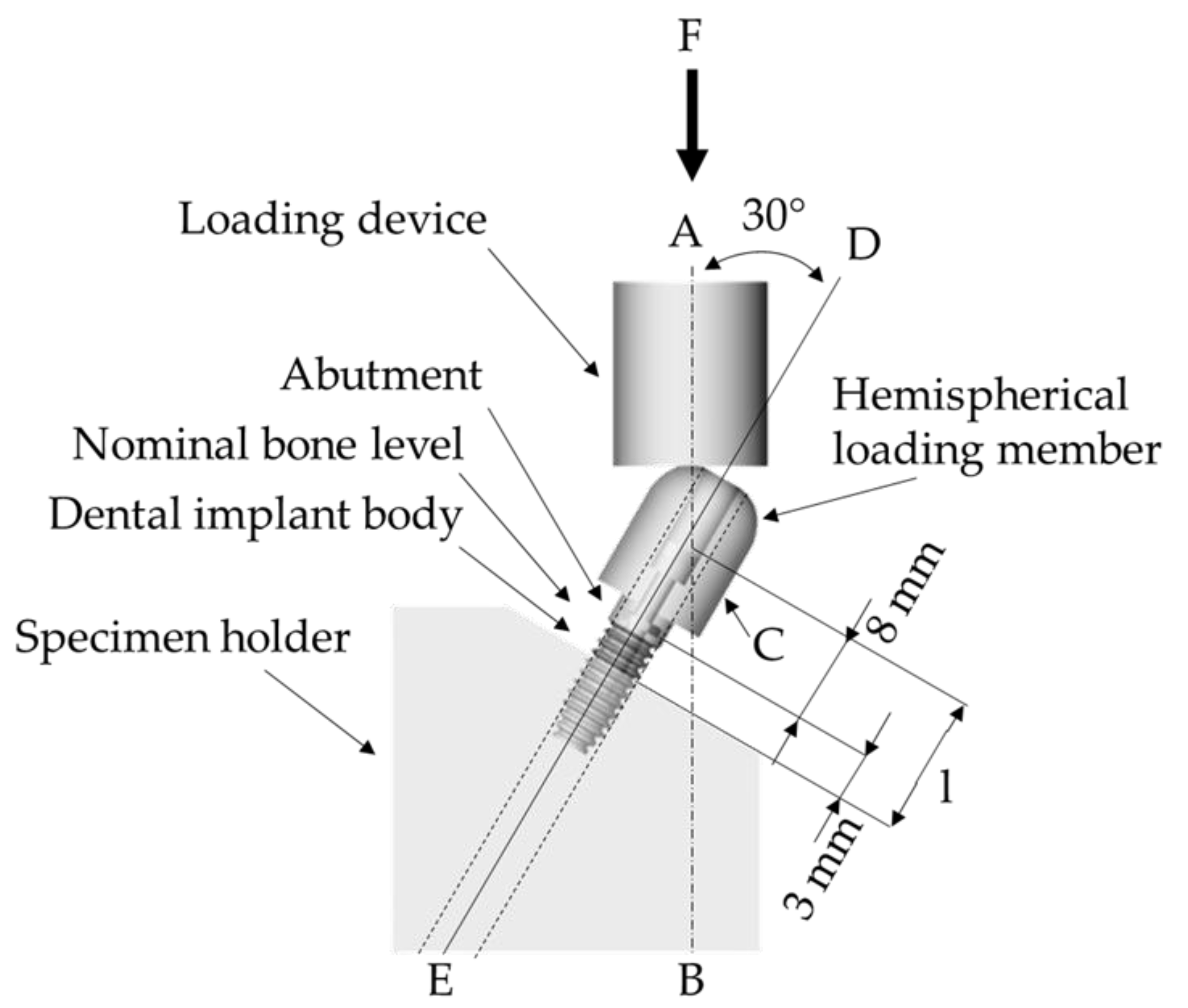
  20. UNE-EN ISO 14801:2016. Dentistry—Implants—Dynamic Loading Test for Endosseous Dental Implants; International Organozation for Standardization: Geneva, Switzerland, 2017. [Google Scholar]
  21. Tribst, J.P.M.; Piva, A.M.D.O.D.; Anami, L.C.; Borges, A.L.S.; Bottino, M. A Influence of implant connection on the stress distribution in restorations performed with hybrid abutments. J. Osseointegration 2019, 11, 507–512. [Google Scholar]
  22. Sahoo, P.; Das, S.K.; Davim, J.P. Tribology of materials for biomedical applications. Mech. Behav. Biomater. 2019, 1–45. [Google Scholar] [CrossRef]
  23. Osman, R.B.; Swain, M.V. A Critical Review of Dental Implant Materials with an Emphasis on Titanium versus Zirconia. Materials 2015, 8, 932–958. [Google Scholar] [CrossRef] [Green Version]
  24. Janeček, M.; Nový, F.; Harcuba, P.; Stráský, J.; Trško, L.; Mhaede, M.; Wagner, L. The Very High Cycle Fatigue Behavior of Ti-6Al-4V Alloy. Acta Phys. Pol. A 2015, 128, 497–502. [Google Scholar] [CrossRef]
  25. Jörn, D.; Kohorst, P.; Besdo, S.; Borchers, L.; Stiesch, M. Three-Dimensional Nonlinear Finite Element Analysis and Microcomputed Tomography Evaluation of Microgap Formation in a Dental Implant under Oblique Loading. Int. J. Oral Maxillofac. Implant. 2016, 31, 32–42. [Google Scholar] [CrossRef]
  26. Tsai, Y.T.; Wang, K.S.; Woo, J.C. Fatigue life and reliability evaluation for dental implants based on computer simulation and limited test data. J. Mech. Eng. Sci. 2013, 227, 554–564. [Google Scholar] [CrossRef]
  27. Prados-Privado, M.; Prados-Frutos, J.C.; Manchón, Á.; Rojo, R.; Felice, P.; Bea, J.A. Dental implants fatigue as a possible failure of implantologic treatment: The importance of randomness in fatigue behaviour. BioMed Res. Int. 2015, 2015, 825402. [Google Scholar] [CrossRef] [Green Version]
  28. Prabhudesai, A.; Dhatrak, P.N.; Padmanabhan, D. Fatigue Life Prediction of Dental Implants. Int. J. Eng. Technol. Comput. Res. 2017, 5, 153–160. [Google Scholar]
  29. Tribst, J.P.M.; Dal Piva, A.M.O.; Borges, A.L.S.; Anami, L.C.; Kleverlaan, C.J.; Bottino, M.A. Survival Probability, Weibull Characteristics, Stress Distribution, and Fractographic Analysis of Polymer-Infiltrated Ceramic Network Restorations Cemented on a Chairside Titanium Base: An In Vitro and In Silico Study. Materials 2020, 13, 1879. [Google Scholar] [CrossRef] [PubMed]
  30. García-González, M.; Blasón-González, S.; García-García, I.; Lamela-Rey, M.J.; Fernández-Canteli, A.; Álvarez-Arenal, Á. Optimized Planning and Evaluation of Dental Implant Fatigue Testing: A Specific Software Application. Biology 2020, 9, 372. [Google Scholar] [CrossRef] [PubMed]
  31. Tribst, J.P.M.; Dal Piva, A.M.D.O.; Borges, A.L.S.; Bottino, M.A. Different combinations of CAD/CAM materials on the biomechanical behavior of a two-piece prosthetic solution. Int. J. Comput. Dent. 2019, 22, 171–176. [Google Scholar] [PubMed]
  32. Tribst, J.P.M.; Dal Piva, A.M.O.; Shibli, J.A.; Borges, A.L.S.; Tango, R.N. Influence of implantoplasty on stress distribution of exposed implants at different bone insertion levels. Braz. Oral Res. 2017, 7, 96. [Google Scholar] [CrossRef] [PubMed] [Green Version]
  33. Datte, C.E.; Tribst, J.P.; Dal Piva, A.O.; Nishioka, R.S.; Bottino, M.A.; Evangelhista, A.M.; Monteiro, F.M.M.; Borges, A.L. Influence of different restorative materials on the stress distribution in dental implants. J. Clin. Exp. Dent. 2018, 10, 439–444. [Google Scholar] [CrossRef]
  34. Adolfi, D.; Mendes Tribst, J.P.; Souto Borges, A.L.; Bottino, M.A. Torque Maintenance Capacity, Vertical Misfit, Load to Failure, and Stress Concentration of Zirconia Restorations Cemented or Notched to Titanium Bases. Int. J. Oral Maxillofac. Implant. 2020, 35, 357–365. [Google Scholar] [CrossRef]
  35. Melo Filho, A.B.D.; Tribst, J.P.M.; Ramos, N.D.C.; Luz, J.N.; Jardini, M.A.N.; Borges, A.L.S.; Santamaria, M.P.; Melo, R.M.D. Failure probability, stress distribution and fracture analysis of experimental screw for micro conical abutment. Braz. Dent. J. 2019, 30, 157–163. [Google Scholar] [CrossRef] [Green Version]
  36. Torres-Alemany, A.; Fernández-Estevan, L.; Agustín-Panadero, R.; Montiel-Company, J.M.; Labaig-Rueda, C.; Mañes-Ferrer, J.F. Clinical Behavior of Short Dental Implants: Systematic Review and Meta-Analysis. J. Clin. Med. 2020, 9, 3271. [Google Scholar] [CrossRef]
  37. Ausiello, P.; Dal Piva, A.M.d.O.; Borges, A.L.S.; Lanzotti, A.; Zamparini, F.; Epifania, E.; Mendes Tribst, J.P. Effect of Shrinking and No Shrinking Dentine and Enamel Replacing Materials in Posterior Restoration: A 3D-FEA Study. Appl. Sci. 2021, 11, 2215. [Google Scholar] [CrossRef]
  38. Martorelli, M.; Ausiello, P. A novel approach for a complete 3D tooth reconstruction using only 3D crown data. Int. J. Interact. Des. Manuf. 2013, 7, 125–133. [Google Scholar] [CrossRef]
  39. Prati, C.; Tribst, J.P.M.; Dal Piva, A.M.d.O.; Borges, A.L.S.; Ventre, M.; Zamparini, F.; Ausiello, P. 3D Finite Element Analysis of Rotary Instruments in Root Canal Dentine with Different Elastic Moduli. Appl. Sci. 2021, 11, 2547. [Google Scholar] [CrossRef]
Figure 1. Schematic of test setup according to the ISO 14801 recommendations.
Oral 01 00009 g001
Figure 2. Numerical model used to the finite element analysis. (A) Geometries with the new coordinate system, (B) meshing subdivision into finite number of elements, (C) boundary conditions with the compressive load, bolt pre-tension and fixation support.
Oral 01 00009 g002
Figure 3. Input data from the fatigue tool based in the von-Mises stress values. (A) S-N curve of Ti-6Al-4V alloy, (B) constant amplitude load applied and (C) mean stress graph theory based in Goodman diagram.
Oral 01 00009 g003
Figure 4. Implant-abutment interfaces simulated in the present study. (A) Minimum contact surfaces with the implant platform only, (B) contact surfaces with external hexagon axial walls touching the abutment.
Oral 01 00009 g004
Figure 5. Convergence results verification. (A) Total deformation after the loading condition, (B,C) microgap formation using the nonlinear contact between implant–abutment.
Oral 01 00009 g005
Figure 6. Stress maps in the implant fixture (AD) and screw (EH). (A,E) Minimum contact interface with 20 N·cm, (B,F) minimum contact interface with 30 N·cm, (C,G) maximum contact interface with 20 N·cm, (D,H) Maximum contact interface with 30 N·cm.
Oral 01 00009 g006
Figure 7. Safety factor maps. (AD) and screw (EH). (A,E) Minimum contact interface with 20 N·cm, (B,F) Minimum contact interface with 30 N·cm, (C,G) Maximum contact interface with 20 N·cm, (D,H) Maximum contact interface with 30 N·cm.
Oral 01 00009 g007
Figure 8. Fatigue life maps. (A) Minimum contact interface with 20 Ncm, (B) minimum contact interface with 30 Ncm, (C) maximum contact interface with 20 Ncm, and (D) maximum contact interface with 30 Ncm.
Oral 01 00009 g008
Figure 9. Microgap size within the implant-abutment interface under 100 N oblique load. (A) Minimum contact interface with 20 Ncm, (B) minimum contact interface with 30 Ncm, (C) maximum contact interface with 20 Ncm, and (D) maximum contact interface with 30 Ncm.
Oral 01 00009 g009
Table 1. Mechanical properties1 of the materials/structures used in the current study.
MaterialElastic Modulus (GPa)Poisson RatioUltimate Tensile Strength (MPa)Yield Strength (MPa)
Fixation base3.60.3--
Titanium1100.3930860
1 Properties simulated in the present study.
Table 2. Tensile stress peaks 1 recorded for implant and screw according to the contacting surfaces and torque.
Torque of Screw Contacting SurfacesStress (MPa)
ImplantScrew
20 NcmAxials and surrounding279283
Surrounding only256374
30 NcmAxials and surrounding268287
Surrounding only253419
1 Information according to the numerical simulation calculation.
Table 3. Safety factor ratio 1 calculated for implant and screw according to the contacting surfaces and torque.
Torque of Screw Contacting SurfacesSafety Factor
ImplantScrew
20 NcmAxials and surrounding1.601.51
Surrounding only1.490.76
30 NcmAxials and surrounding1.611.44
Surrounding only1.500.72
1 Information according to numerical simulation
Table 4. Predicted cycles 1 to failure for implant and screw according to the contacting surfaces and torque.
Torque of Screw Contacting SurfacesLife (Cycles)
ImplantScrew
20 NcmAxials and surrounding1 × 10101 × 1010
Surrounding only1 × 101063,567
30 NcmAxials and surrounding1 × 10101 × 1010
Surrounding only1 × 101057,389
1 Information according to the numerical simulation
Table 5. Maximum microgap (mm) value 1 recorded for implant and screw according to the contacting surfaces and torque.
Torque of Screw Contacting SurfacesMicrogap (mm)
Interface Implant-Abutment
20 NcmAxials and surrounding0.000861
Surrounding only0.001817
30 NcmAxials and surrounding0.000820
Surrounding only0.001751
1 Information according to the numerical simulation.
Publisher’s Note: MDPI stays neutral with regard to jurisdictional claims in published maps and institutional affiliations.

