1. Introduction
Long-period fiber gratings (LPFGs) are versatile components widely studied with relevant applications in telecommunications, fiber-optic lasers, and sensing systems [
1,
2,
3]. Concerning sensing applications, LPFGs offer high sensitivity to external perturbations of the surrounding medium, immunity to electromagnetic fields, passive measurements, fast response, low insertion loss, small backscattering, compactness, and remote monitoring. These properties make LPFGs very attractive in developing physical, chemical, and biological fiber optic sensors [
4,
5,
6]. Currently, several methods have been reported to produce LPFGs, such as exposure to ultra-violet (UV), electric arc discharge, CO
2 laser radiation, femtosecond laser radiation, mechanical pressure, hydrogen-oxygen flame heating, and ion implementation, among others [
7,
8,
9,
10,
11,
12,
13]. Despite the progress made in the fabrication methods of LPFGs, there are still some challenges to harnessing the potential of LPFGs in sensing applications, such as the development of low-cost interrogation systems [
14] and the optical fiber distributed sensing applications by the wavelength-division multiplexing of LPFGs in cascade.
Two different approaches have been reported for the optical fiber distributed sensing applications with wavelength-division multiplexing of LPFGs. The first method uses two similar concatenated LPFGs to conform a Mach–Zehnder interferometer [
15]. In this way, one can have two or more Mach–Zehnder interferometers with distinct cavity lengths in series to measure different parameters simultaneously [
16,
17]. However, interferometric optical fiber sensors produce differential outputs. Therefore, they require complex demodulation techniques such as filtering the carrier frequencies in the frequency domain and the unwrapped phase processes to extract the external perturbations [
18]. The second method entails implementing two or more different LPFGs in series in such form that their reference rejection bands do not overlap and operate independently [
19,
20,
21,
22]. Although these schemes require simple demodulation techniques, the wavelength-division multiplexing of LPFGs is delimited because LPFGs usually generate multiple rejection bands. However, mechanically induced long-period fiber gratings (MI-LPFGs) with a primary rejection band have recently been reported using laminated plates [
23]. Such MI-LPFGs with a principal rejection band facilitate the use of the CWDM technique for LPFG sensors in cascade.
In this report, we demonstrate experimentally the simultaneous measurement of transverse load and temperature using two multiplexed long-period fiber gratings. For this, an MI-LPFG is connected with a CO
2 LPFG in cascade to measure transverse load and temperature, respectively. These LPFGs are notable for having a prominent attenuation band over a wide wavelength range. As far as we know, this is the first time that the technique of wavelength-division multiplexing using LPFGs with a prominent attenuation band is presented. The work’s structure comprises the following sections:
Section 1 explains an antecedent on the two approaches of the multiplexing LPFGs reported previously, highlighting their scope and limitations. The relevance of the wavelength-division multiplexing technique using LPFGs with a prominent attenuation band and their application in distributed sensing is also presented. The general principle of the phase-matching in LPFGs is described in
Section 2.
Section 3 describes the experimental arrangement and its principal features. Also, it describes in detail the implementation of the MI-LPFG and the inscription of the CO
2 LPFG. In
Section 4, the individual characterization of the MI-LPFG and the CO
2 LPFG is presented when the LPFGs are under transverse load and temperature, respectively. Also, we show the simultaneous measurement of transverse load and temperature. Finally,
Section 5 presents the most relevant findings of the work.
2. LPFGs Principle
Long-period fiber gratings result from a periodic refractive index modulation produced in the core of a single-mode optical fiber. The long-period fiber gratings operate as modal couplers allowing the light transfer from the fundamental mode in the core
to different co-propagating high-order cladding modes
. This coupling results in a discrete set of rejection bands in the grating transmission spectrum due to the scattering of the high-order cladding modes at the interface between the cladding and the external medium. Where the resonant central wavelength
of the individual rejection bands must fulfill the phase-matching condition [
7],
where
and
represent the effective refractive indices of the
mode in the core and the
mode in the cladding, respectively, and
is the period of the refractive index modulation in the long-period fiber grating.
The number of rejection bands in an LPFG depends upon the structure and material composition of the host single-mode optical fiber and the corresponding refractive index modulation. In general, LPFGs in single-modal optical fiber with a cosinusoidal refractive index modulation and a typical period from
, usually present spectrum transmissions with three to five rejection bands in the spectral range from 1200–1700 nm [
7], where the attenuation depth of the rejection bands typically is more profound as the coupling mode’s order of the cladding increases. LPFGs with this number of the rejection bands and their spectral side lobes limit the wavelength-division multiplexing of LPFGs in cascade [
16]. However, in the last years, it has been shown that LPFGs with a primary rejection band over a wide wavelength range using different inscription techniques is feasible [
23,
24,
25,
26,
27]. Long-period fiber gratings with a primary rejection band facilitate the deployment of fiber optic distributed sensing systems based on the wavelength-division multiplexing of LPFGs.
3. Setup and Components
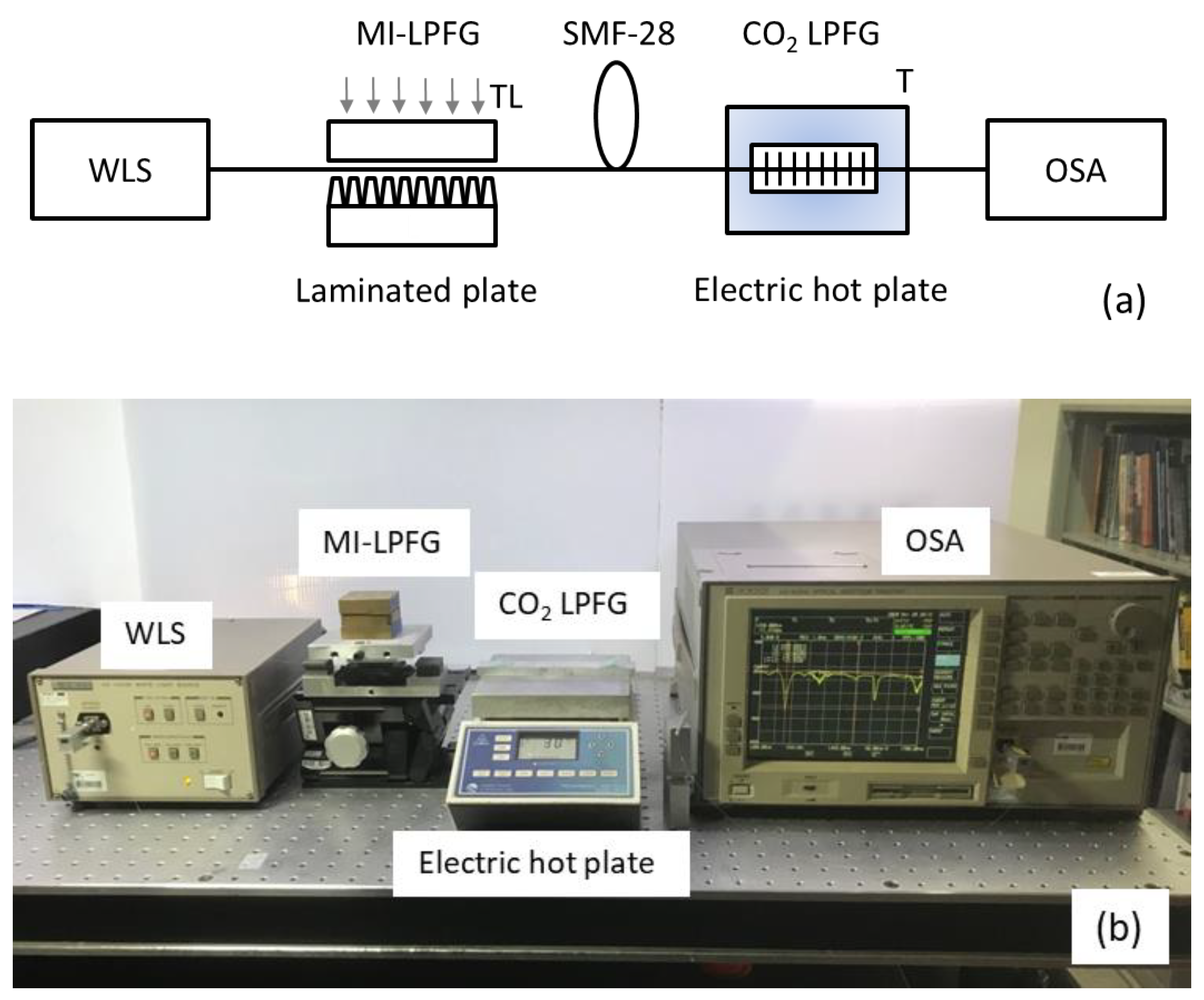
Figure 1a illustrates the experimental configuration schematic for measuring the transverse load (TL) and the temperature (T) by the multiplexed LPFGs. The experimental setup consisted of an MI-LPFG connected to a CO
2 LPFG in cascade. The CO
2 LPFG was located over an electric hot plate where the temperature can be manually controlled. The input end of the MI-LPFG was connected to a white light source (WLS; AQ-4303B), and the output end of the CO
2 LPFG was connected to an optical spectrum analyzer (OSA; AQ-6315A). For each proof, the transmission spectrum of the cascaded LPFGs was recorded by the optical spectrum analyzer, while the spectral resolution was set to 1 nm. The fiber used in the double grating configuration is a standard single-mode fiber (SMF-28) for telecommunications. The LPFGs were separated 10 cm in the single-mode optical fiber.
Figure 1b illustrates the photography of the experimental configuration.
The MI-LPFG can be achieved when the optical fiber is compressed between a flat aluminum plate and a laminated plate, see
Figure 1b. The laminated plate consisted of a parallel assembling of single-edged utility blades [
23]. The laminated plate had a length of approximately 30 mm, an average period of 490 ± 10 µm, and an average duty cycle of the refractive-index modulation of 0.2.
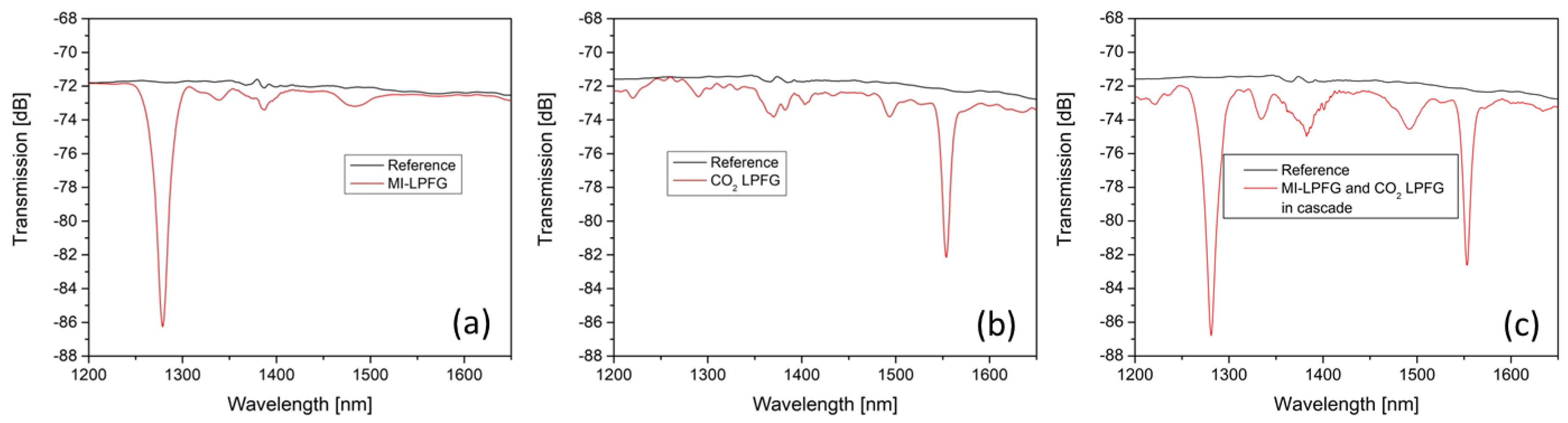
Figure 2a shows the transmission spectrum of the MI-LPFG when a constant transverse load of 2000 g is applied between the plates. As can be seen, its spectrum transmission shows a primary rejection band at 1279.3 nm with a sidelobe at 1338.4 nm and shallow rejection bands at 1386.0 and 1484.2 nm. The primary rejection band’s attenuation depth was 14.4 dB, whereas the attenuation depth for the lateral shallow rejection bands was lower than 1.5 dB. According to the reference spectrum transmission of the MI-LPFG, its average insertion loss is lower than 0.25 dB for the above conditions. It should be noted that the MI-LPFG has no attenuation bands in the spectral range from 1540–1640 nm, although a small portion of light can propagate through the cladding, as can be inferred from the background loss induced by the MI-LPFG in that spectral range.
On the other hand, the CO
2 LPFG was inscribed using a continuous-wave CO
2 laser glass processing system (Laser Master LZM-100). It has a length of 37.5 mm and a period of 0.75 mm. In the inscription process, a fiber section is heated during 120 ms with a power discharge of 20 W; then, with the same power, the fiber is pulled for 60 ms. In order to have a principal rejection band in the spectral range of 1540–1580 nm, a period of 0.75 nm was determined empirically based on an extensive experimental study.
Figure 2b shows its transmission spectrum. As can be seen, the transmission spectrum displays a primary rejection band at 1553.8 nm with 9.8 dB and shallow rejection bands at 1220.2, 1289.7, 1370.8, and 1493.7 nm with attenuation depths lower than 2.2 dB. According to the reference spectrum transmission, the average insertion loss is lower than 0.85 dB. The insertion loss is due to the scattering produced by the heated points irradiated by the continuous-wave CO
2 laser. The CO
2 LPFG was fixed on an aluminum holder (12 × 2 × 1 cm) by commercial epoxy putty. The CO
2 LPFG was sat on the aluminum holder by pasting its two ends with a physical separation of 10 cm. Then the aluminum holder with the CO
2 LPFG was placed over the electric hot plate, see
Figure 1b. The maximum operating temperature of the epoxy putty was 110 °C. For its part,
Figure 2c illustrates the transmission spectrum of the MI-LPFG and the CO
2 LPFG in cascade when a constant transverse load of 2000 g is applied in the MI-LPFG. We can observe the primary rejection bands of the LPFGs and the overlapping of their shallow rejection bands. The insertion loss of the cascaded LPFGs is less than 1.1 dB regarding the reference transmission spectrum.
4. Experiment and Results Analysis
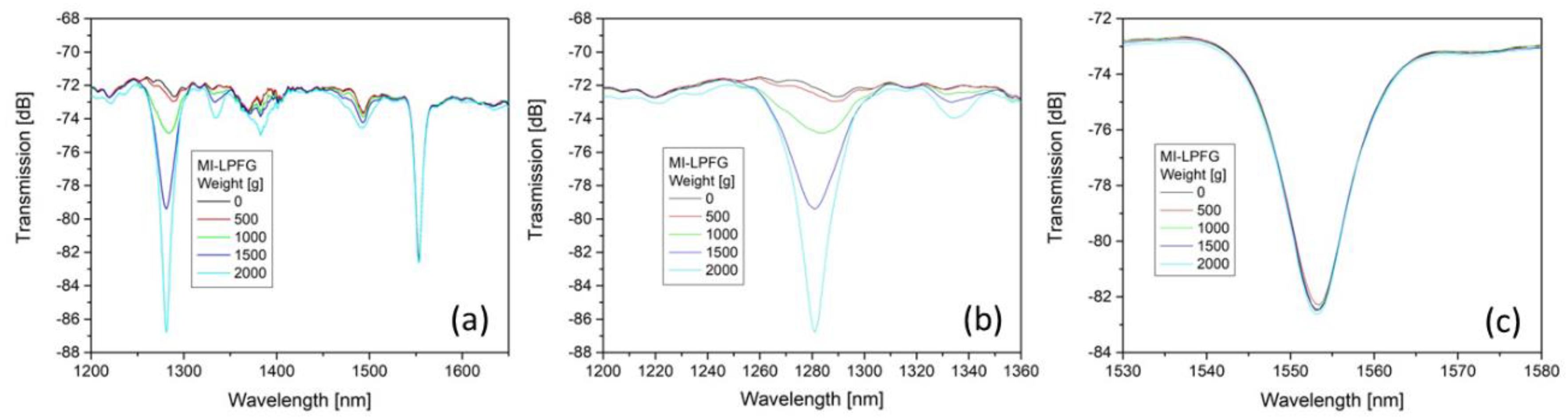
Once the experimental setup was installed, the transverse load on the MI-LPFG was increased from 0 to 2000 g with increments of 500 g, while the CO
2 LPFG remains unloaded. Both LPFGs in the proofs stayed at room temperature (27 ± 3 °C).
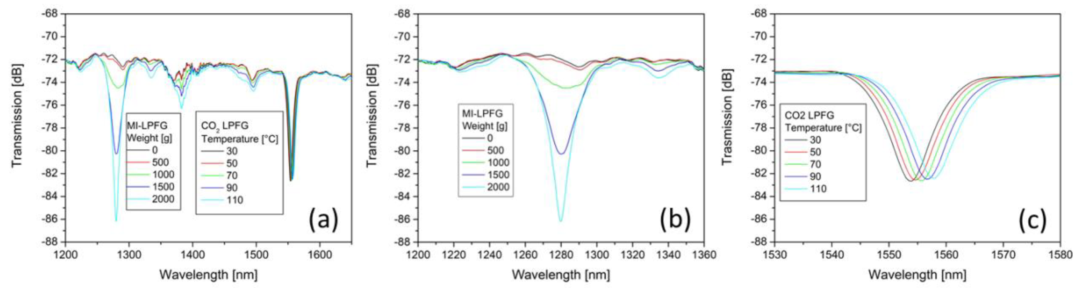
Figure 3a shows the transmission spectrum evolution of the multiplexed LPFGs when the load on the MI-LPFG increases. As a result, the attenuation depth of the leading rejection band of the MI-LPFG got more profound as the transverse load increased. In contrast, the attenuation depth of the principal rejection band of the CO
2 LPFG remains practically unchanged.
Figure 3b,c shows the spectrum transmission evolution of the primary rejection bands of the multiplexed LPFGs when the transverse load increases. No wavelength shift is observed in the MI-LPFG primary rejection band. In contrast, the principal rejection band of the CO
2 LPFG presents a tiny wavelength shift to larger wavelengths that can be practically considered negligible.
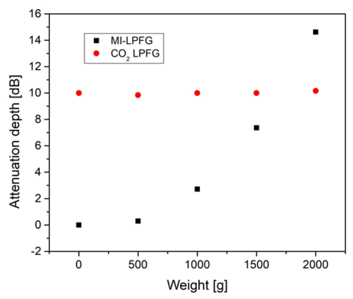
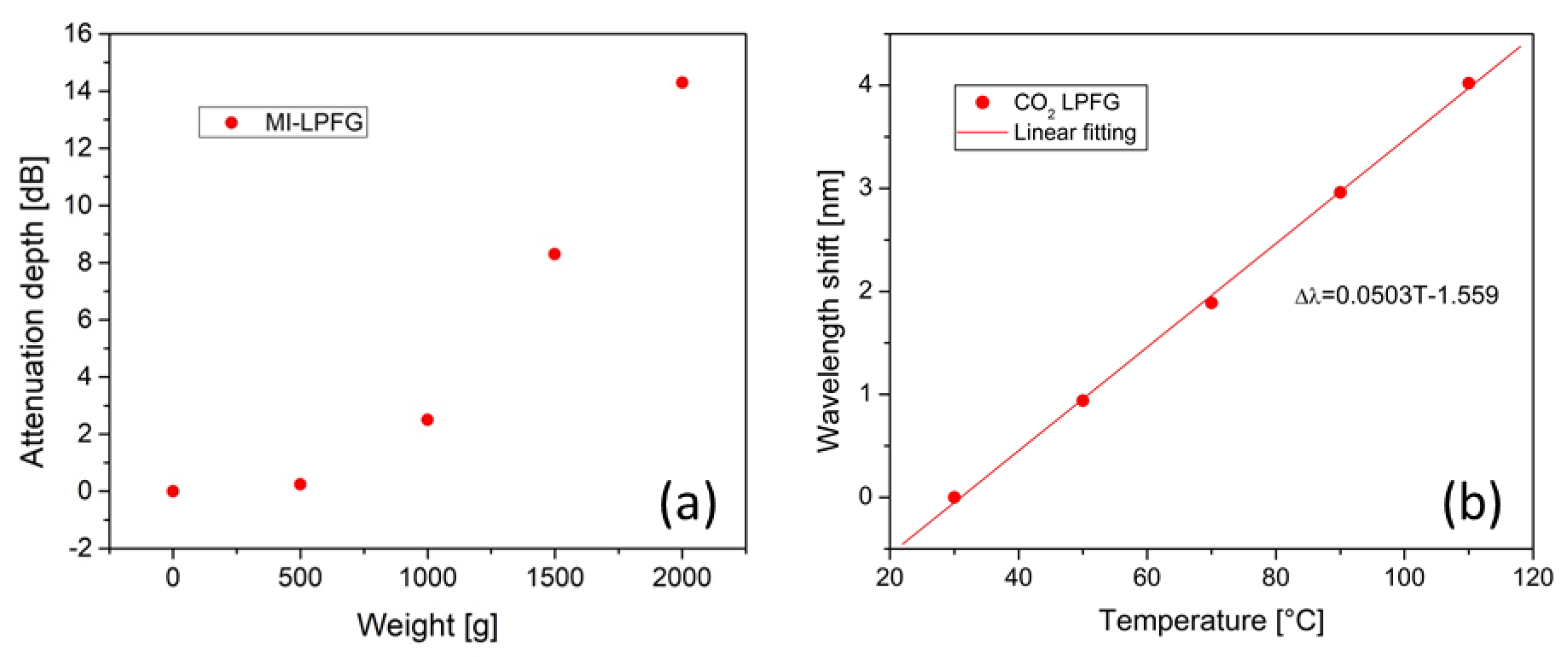
Figure 4 illustrates the attenuation depth evolution of the primary rejection bands of the multiplexed LPFGs versus the transverse load on the MI-LPFG. The leading rejection band of the MI-LPFG presents a nonlinear increase, while the attenuation depth of the principal rejection band of CO
2 LPFG shows a small variation. It is important to note that the shallow rejection bands of the MI-LPFG also got deeper when the transverse load increased, but they do not interfere with the primary rejection band of the CO
2 LPFG.
Next, the temperature in the CO
2 LPFG was increased from 30 to 110 °C by steps of 20 °C using an electric hot plate, whereas the MI-LPFG with a constant transverse load of 2000 g was kept at room temperature.
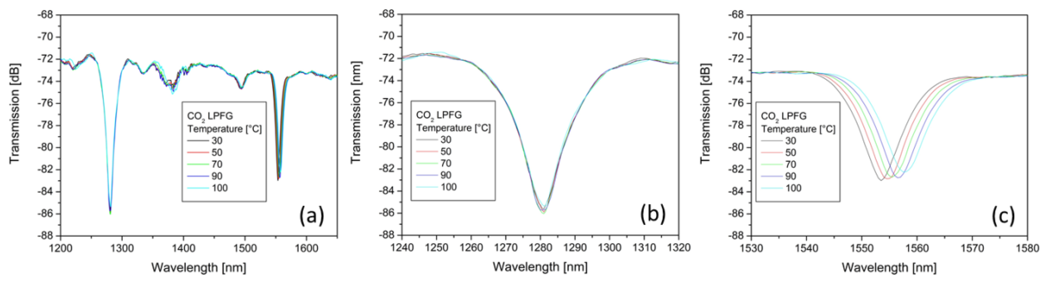
Figure 5a shows the transmission spectrum evolution of the multiplexed LPFGs when the temperature in the CO
2 LPFG was increased.
Figure 5b,c shows the transmission spectrum evolution of the primary rejection bands of the multiplexed LPFGs. As can be seen, the rejection band of the CO
2 LPFG shifted towards longer wavelengths with a slight decrease in the attenuation depth. Meanwhile, the leading rejection band of the MI-LPFG presents small variations in the attenuation depth and wavelength shift.
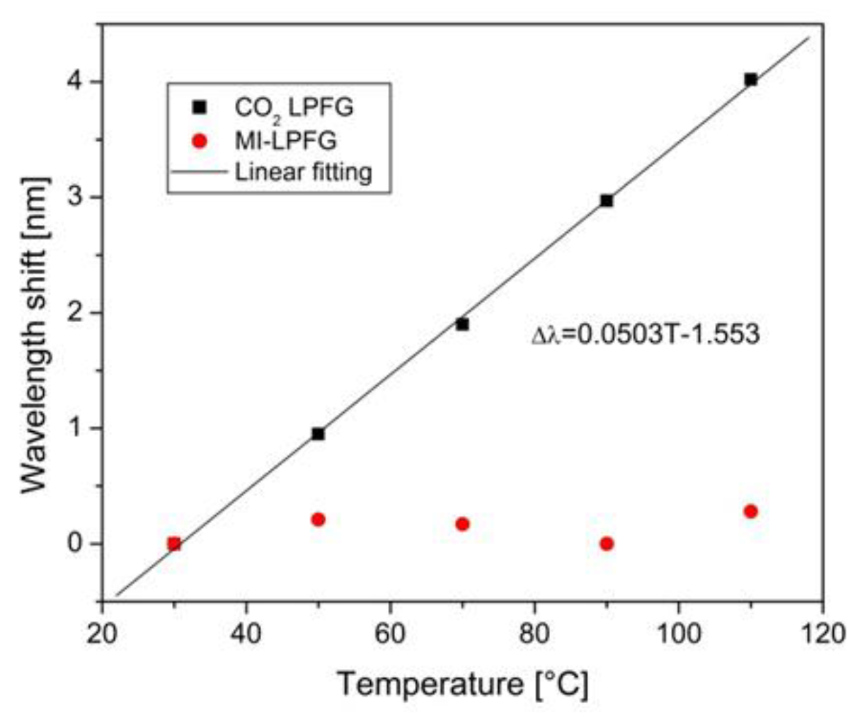
Figure 6 shows the wavelength shift of the primary rejection bands of multiplexed LPFGs concerning the spectrum transmission of the multiplexed LPFG at 30 °C. The CO
2 LPFG principal rejection band shows a linear wavelength shift when the temperature is increased. This rejection band shows a temperature sensitivity of
50 pm/°C, and its R-squared factor of the linear fitting is 0.9989. On the other hand, the MI-LPFG leading rejection band presented a small oscillating wavelength shift due to the overlapping with the shallow rejection bands at 1289.7 nm of the CO
2 LPFG. Similarly, the attenuation depth of the leading rejection band of the MI-LPFG is slightly altered.
Then, the transverse load on the MI-LPFG and the temperature in the CO
2 LPFG were simultaneously measured. Thus, the transverse load was increased from 0 to 2000 g by increments of 500 g in the MI-LPFG, while the temperature was also increased from 30 to 110 °C by steps of 20 °C in the CO
2 LPFG.
Figure 7a shows the transmission spectrum evolution of the multiplexed LPFGs for these conditions.
Figure 7b,c shows the primary rejection bands evolution of the multiplexed LPFGs when the transverse load and the temperature were increased, respectively.
Figure 8a shows the leading rejection band’s attenuation depth behavior in the MI-LPFG when the transverse load increases for different temperatures at the CO
2 LPFG. The attenuation depth shows a nonlinear increase, similar to the results obtained previously in
Figure 4. On the other hand,
Figure 8b shows the principal rejection band’s wavelength shift in the CO
2 LPFG with respect to spectrum transmission at 30 °C for the above conditions. The principal rejection band’s center wavelength in the CO
2 LPFG shows a linear wavelength shift towards longer wavelengths. The rejection band shows a temperature sensitivity of
50 pm/°C, and its R-squared factor of the linear fitting was 0.9986.
The MI-LPFG displays a leading rejection band at 1280 ± 1 nm, while the CO
2 LPFG presents a principal rejection band at 1553.80 nm at room temperature (27 °C). The wavelength separation between the primary rejection bands allows the CWDM of LPFGs with low cladding-mode crosstalk. When the transverse load in the MI-LPFG was increased from 0–2000 g, the principal rejection band of the CO
2 LPFG underwent attenuation depth variations lower than ±0.2 dB and a wavelength shift lower than ±0.2 nm with respect to the initial spectrum transmission. We assume that these random variations are due to the white light source output power stability combined with the insertion loss induced by the MI-LPFG. Note that the MI-LPFG transverse load sensitivity was obtained at a constant room temperature. However, it is well known that attenuation depth and the central wavelength location of the rejection bands are influenced by the temperature on the MI-LPFGs [
28]. It had been observed that with a temperature increase on the MI-LPFGs, the rejection bands shift to longer wavelengths, and their attenuation depth partially decreases. In this sense, to include the effect of the temperature on the MI-LPFG response, the transverse load sensitivity, and the wavelength shifting sensitivity of the principal rejection band can be calibrated at different temperatures. On the other hand, when the temperature in the CO
2 LPFG was increased from 30 to 110 °C, the leading rejection band in the MI-LPFG experienced an attenuation depth variation lower than ±0.4 dB and a wavelength shift lower than ±0.3 nm with respect to the initial spectrum transmission. We assume that these variations are also due to the white light source output power stability and the overlapping between the leading rejection band in the MI-LPFG and the CO
2 LPFG shallow rejection band at 1289.7 nm. In the last case, increasing the separation between the LPFGs can significantly reduce the overlapping effect since cladding light will be attenuated by the high index polymer coating of the optical fiber section between LPFG. On the other side, the random variations of the power transmission spectrum introduced by the white light source can be eliminated using a broadband light source by combining two superluminescent diodes at 1280 and 1550 nm.
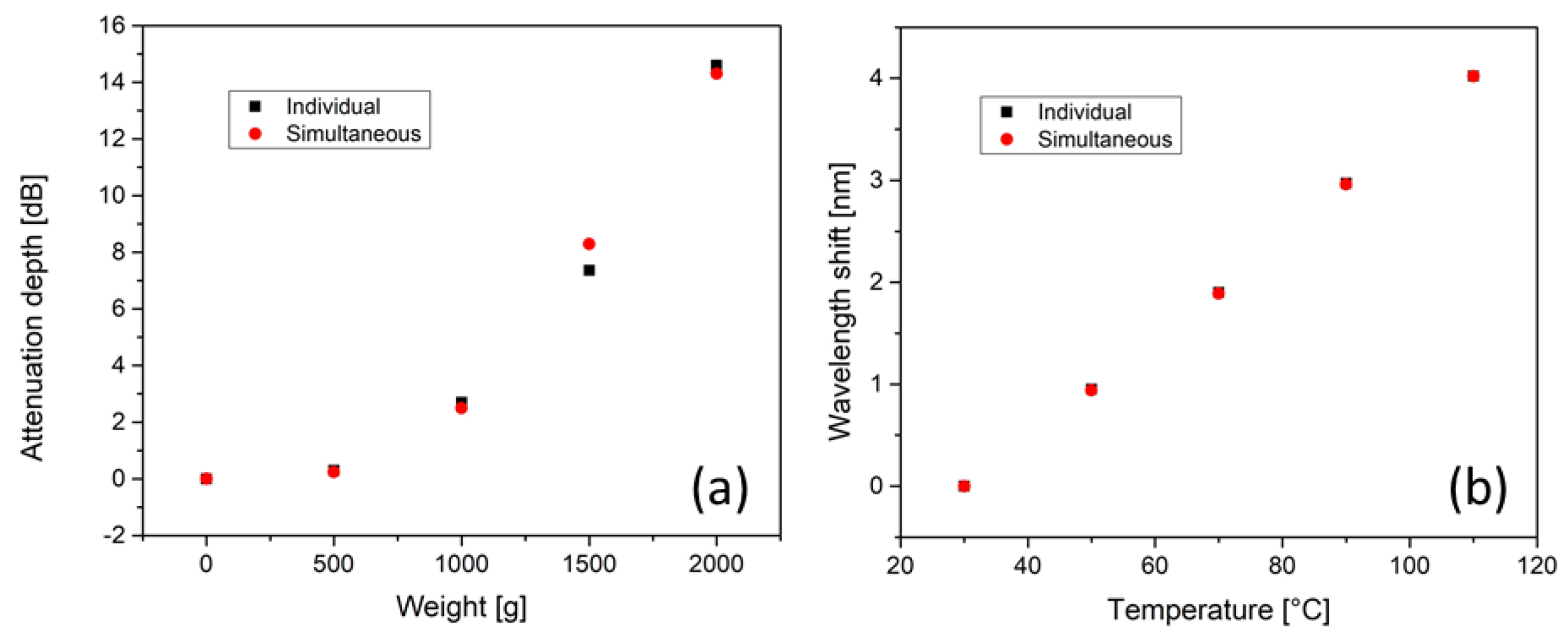
The above results were replicated when we simultaneously measured the transverse load and the temperature in the multiplexed LPFGs, respectively.
Figure 9a displays a comparison between the individual and simultaneous measurement of the attenuation depth in the MI-LPFG. As can be seen, except for the attenuation depth corresponding to 1500 g, the remainder attenuation depth points preserve a close correlation. This difference at 1500 g can be due to the repeatability of the MI-LPFG. Meanwhile,
Figure 9b illustrates a comparison between the wavelength shift in the CO
2 LPFG for the individual and simultaneous temperature measurement, where one can observe a close correlation between individual and simultaneous measurements of the temperature. According to these results, the multiplexed LPFGs operate with low cladding-mode crosstalk. The experimental results demonstrate the simultaneous measurement of transverse load and temperature by the multiplexed LPFGs. The current multiplexed LPFGs arrangement uses an MI-LPFG; however, it is possible to produce LPFGs with a primary rejection band by other inscription methods such as electric arc discharge and femtosecond laser irradiation [
25,
26,
27]. These LPFGs may allow more flexible schemes of distributed sensing applications based on multiplexed LPFGs in cascade.

 ,
, 


