Electron Spill-Out Effect in Singular Metasurfaces


1
Department of Electrical and Computer Engineering, University of California, San Diego, CA 92093, USA
2
State Key Laboratory of Surface Physics and Key Laboratory of Micro and Nano Photonic Structures (Ministry of Education), Department of Physics, Fudan University, Shanghai 200438, China
*
Author to whom correspondence should be addressed.
Photonics 2021, 8(5), 154; https://0-doi-org.brum.beds.ac.uk/10.3390/photonics8050154
Submission received: 28 March 2021
/
Revised: 1 May 2021
/
Accepted: 2 May 2021
/
Published: 5 May 2021
(This article belongs to the Special Issue Plasmonic Metasurfaces)
Abstract
:The electron spill-out effect is considered in a singular metasurface. Using the hydrodynamic model, we found that electron spill-out effectively smears the sharp singularity. The introduction of the electron spill-out effect also significantly changes the reflection spectrum, charge distribution, field profile for a singular metasurface. Therefore, this spill-out contribution is crucial and cannot be ignored for a realistic description of optical response in a singular system.
1. Introduction
Plasmonic metasurfaces [1] have been a hot topic in the past decade and have been used in many applications, such as wave-front control [2,3], wave absorbing [4,5], imaging [6,7], and so forth. As a subset of plasmonic metasurfaces, singular metasurfaces [8,9] have one additional hidden dimension. In contrast, to conventional metasurfaces which require specific incident wave-vectors for surface plasmon excitation, singular metasurfaces give rise to excitations at arbitrary incident wave vectors. Because of this unique property, singular metasurfaces can be used as broadband electromagnetic absorbers, an example being a black gold surface [10].
A singular metasurface has sharp points or narrow gaps, which are called “singularities”. These singularities are so tiny that a macroscopic permittivity cannot accurately describe the local optical properties because of the quantum nature of electrons. Thus, the quantum effect of electrons should be considered near a singularity. These quantum effects mainly include nonlocality [11] and electron spill-out [12]. Nonlocality is attributed to the wave nature of electrons combined with the Pauli exclusion principle, and point like charges are surrounded in the electron gas not by a point like screening charge but by a finite cloud of electrons whose extent is determined by the Thomas-Fermi screening length (typically less than one angstrom) [13]. This limitation sets the bound for the electric field enhancement. Besides, the electron spill-out effect means that electrons can leak out of the metal surface, where the length scale of spill-out is characterized by Feibelman’s d parameters (typically a few angstroms) [14]. Such a small length scale makes the spill-out effect observable only in a nanometer-size metallic particle [15] or a sub-nanometer gap [16].
To fully account for these quantum effects in plasmonic systems, a time-dependent density functional theory (TD-DFT) [17,18,19] approach is required. However, this DFT approach is quite time-consuming, especially for a large-number electron system. Luckily, alternative methods, such as the hydrodynamic model, can handle these quantum effects in a semi-classical way, avoiding solving many-body Schrödinger equations. The simplest model is the hard-wall hydrodynamic model (HW-HD) [20,21], which incorporates the nonlocal contribution from electrons. More recently, a more advanced model that considers both nonlocality and spill-out is proposed, named as the self-consistent hydrodynamic model (SC-HD) [22,23,24,25].
In our previous work on singular plasmonic systems, we have only incorporated the contribution of nonlocality, which shows that the nonlocal effect strongly changes the spectrum of the system. A continuous spectrum in the local case becomes discrete once the nonlocal contribution of the electron is taken into account [26,27,28]. However, the electron spill-out effect was ignored in these calculations, and its role in the singular system is still unknown. In this paper, we utilize two models (SC-HD and HW-HD) in the calculation of the optical response of singular metasurfaces and compare them with classical local response approximation (LRA). For simplicity, a simple metal without inter-band transitions is studied to clarify the role of electron spill-out from the singular metasurface.
2. Methods
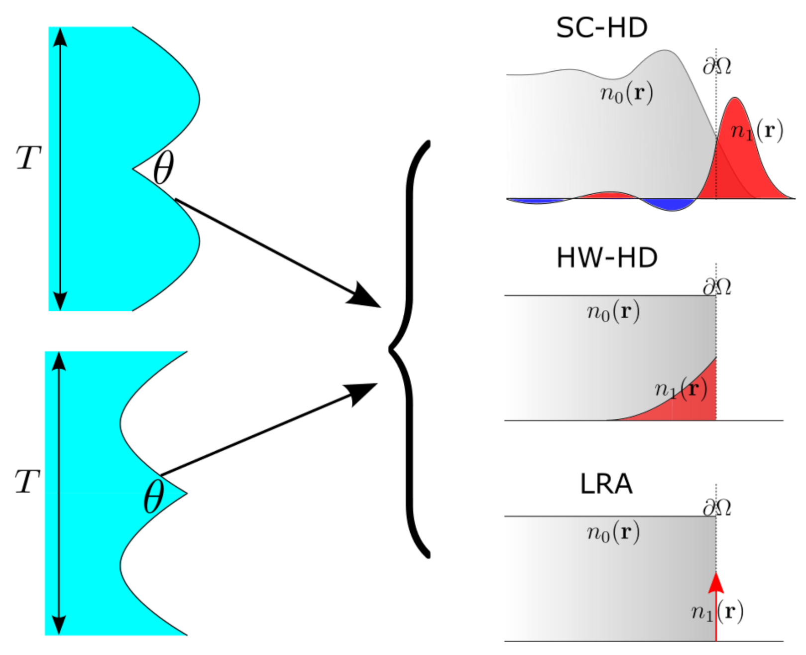
The schematic for this paper is shown in Figure 1. We consider both groove (upper one in the left panel) and wedge (lower one in the left panel) singular metasurfaces, which are parameterized with the period T and vertex angle [9]. On the right panel of Figure 1, we conceptually illustrate the electron density distribution near the metal interface . The total electron density n can be decomposed into the ground state and the excited state , where corresponds to equilibrium electron density in the absence of field excitation, while to electron density induced by an incident field [29].
For SC-HD, the normalized electron density of the ground state ( normalized by ion density ) continuously transitions from 1 to 0 across the boundary , where the electron density exhibits some oscillations termed Friedel oscillations [29]. Likewise, the induced electron density, , spills out of the metal surface and strongly oscillates near the interface. In comparison, the equilibrium electron density in both HW-HD and LRA becomes a step function [22], which means is discontinuous at . Moreover, the induced density for HW-HD only oscillates inside the metal, while for LRA becomes a delta function at . In the LRA, there is no constraint on the electron density so that it becomes infinite. Once imposing a constraint, such as that in SC-HD and HW-HD, the induced electron density becomes finite.
For the electrons in the metal, the equation of the motion can be expressed as [22,23,24,25]
together with the continuity equation for electron density, n
where , , and are the mass, the charge, and the velocity of the electron, respectively. Note that the in the Equation (1) is the damping term. The functional represents the internal energy of the electron gas, which includes internal kinetic energy and the exchange-correlation energy [18]. The detailed expression of the functional derivative of is given in Yan’s work [23].
The electron density in the above system of equations can be written as , where the induced electron density is treated as a perturbation. The electron at equilibrium is also assumed to be motionless so that , and hence the magnetic field appears when the system is perturbed, expressed as . However, the static electrons support an electric field , so the electric field is formulated as . Likewise, we also calculate the perturbation for the derivative of the energy functional , written as [22].
Using perturbation theory, the equation system Equations (1) and (2) can be divided into two sets of equations: zero-order ground state and first-order excited state. The zero-order equation system is given as [22,23,24,25]
which collectively determine the ground state charge density of plasmonic system. Note that in the ground state calculation, the jellium model is used for the ion, in which the ion density is uniform inside the interface but 0 outside [29]. In equation system above, is the jellium background density such that , is the chemical potential, and is the electrostatic potential defined by .
In contrast, the first-order system of equations is written as [22,23,24,25]
which couples with Maxwell’s equation
where the induced current and the induced charge density . is the total electric field including incident and scattered fields. Equations (6)–(8) together determine the excited state.
The difference between SC-HD, HW-HD and LRA mainly comes from the functional derivative . For SC-HD, this functional derivative includes contributions from the Thomas-Fermi kinetic energy, the von Weizsäcker(VW) energy and the exchange-correlation energy [30,31]. When only Thomas-Fermi kinetic energy is considered, we arrive at HW-HD. Thomas-Fermi kinetic energy only accounts for the homogeneous electron gas. To account for the inhomogeneity of electron gas, we need to consider high-order terms, where von Weizsäcker(VW) energy is the second order correction. Note that von Weizsäcker(VW) energy contains derivative terms like , which becomes important and indispensable near the interface where the electron density, n, oscillates strongly. For the LRA, the functional derivative is completely ignored, so that everything becomes local.
The ground state and excited state equations can be implemented with the finite-element method in the commercial software COMSOL Multiphysics. We first numerically solve Equations (3)–(5) to obtain the ground-state electron distribution . After that, a second calculation solving Equations (6)–(8) gives the excited state, including reflection spectrum, induced charge distribution, electric field, and so forth. The detailed implementation in Comsol can be found in Ding’s work [25].
3. Results
In this section, we employ the SC-HD, HW-HD and LRA models to calculate the optical response of two singular metasurfaces in Figure 1. In the calculation, we consider the case of a simple metal, like sodium. The corresponding ion density is , from which we obtain the plasma frequency [32]. Besides, the damping parameter is [22]. The geometric setup for the singular metasurface is nm and rad. Excitation is by a plane wave incident normally on the singular metasurface.
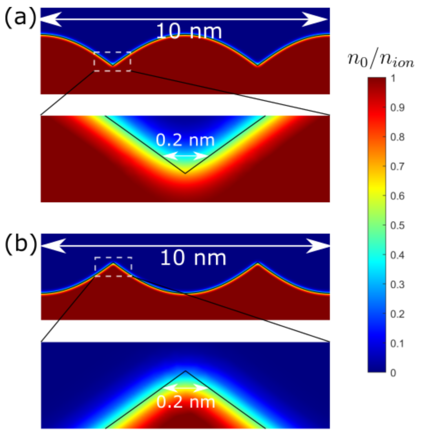
The ground state calculation is shown in Figure 2. The normalized equilibrium electron densities of groove and wedge singular metasurfaces are presented in Figure 2a,b, respectively. It is obvious that the electron has some distribution outside the metal surface (the black curve), which is the spill-out effect we are concerned about. Because of this electron spill-out, the region immediately outside has a negative net charge, while the region immediately inside has a positive net charge, which contributes to a dipole layer in the ground state. Despite geometric singularities in the jellium background , the ground state electron smears out this sharp point, making it as far as the electron are concerned an effectively blunt singular metasurface [9]. We have also marked the length scale in the figure, which shows this blunt tip has an around 2 Å diameter. In contrast, the ground states for both HW-HD and LRA possess a step-function distribution rather than a continuous transition in the case of SC-HD.
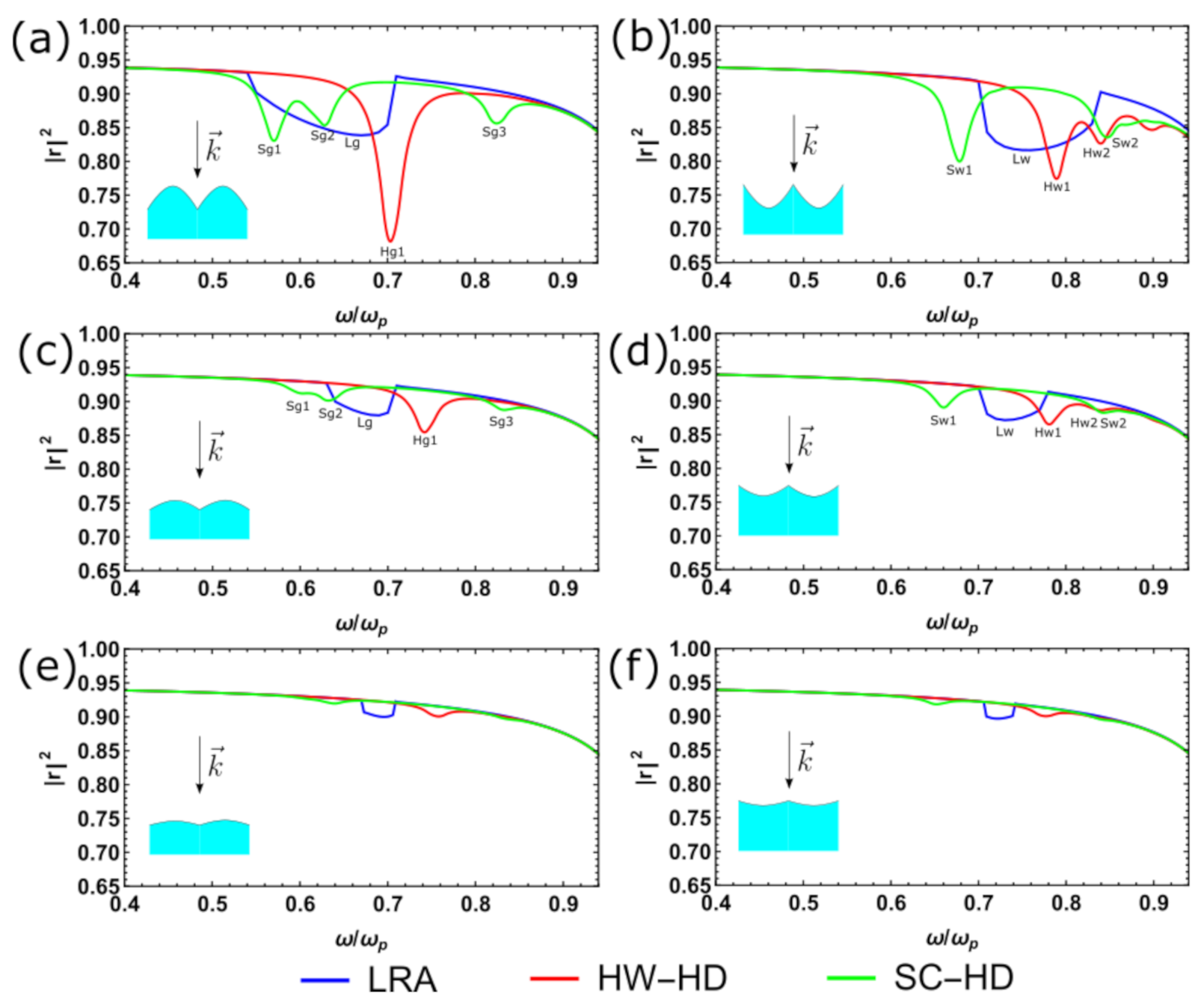
With ground-state electron distribution determined, we can next calculate the excited state. We compare the reflection spectrum for SC-HD, HW-HD, and LRA cases in Figure 3, where Figure 3a,b correspond to groove and wedge singular metasurfaces, respectively. For LRA, we have previously demonstrated that the reflection is a continuous spectrum [9]. For a groove singular metasurface, the lower band Lg () is exited while the upper band () is a dark mode under normal incidence, where the notation “Lg" means the LRA mode for groove singular metasurface (“L” is short for LRA and “g” stands for groove), is the surface plasmon frequency and is the cut-off frequency. On the contrary, the wedge singular metasurface only supports upper-band mode Lw, leaving the lower band as a dark mode.
However, when the Thomas-Fermi kinetic energy is considered, the reflection spectrum ceases to be continuous but instead has a discrete spectrum [28]. In both Figure 3a,b, a broadband continuous spectrum in LRA becomes a few discrete peaks in HW-HD, that is, Hg1, Hw1 and Hw2. The notation rule is the same as that in LRA except for the additional number which defines the discrete mode index. Now, we take the electron spill-out effect into account, which requires a full consideration of all energy contributions in functional derivative , as shown in SC-HD case in Figure 3. The reflection spectra of SC-HD exhibit distinct features comparing with other two cases. For the groove singular metasurface, we observe that the Sg1 and Sg2 peaks tend to redshift relative to the Lg band, while the Hg1 peak relatively blueshifts. Similar peak shifting can be observed in the wedge singular metasurface.
As a free parameter, characterizes the shape of the singular metasurface. In Figure 3c,d, we implement the same calculation as in Figure 3a,b except that the vertex angles for the corresponding groove and wedge singular metasurfaces are rad. For LRA, the bandwidth of both groove and wedge singular metasurfaces become narrower when the vertex angle is increased from to . From the reflection spectrum of the LRA, we observe that the shifting of the cut-off frequency effectively blueshifts the central frequency of band Lg for the groove singular metasurface, while redshifting the central frequency of band Lw for the wedge singular metasurface. In Figure 3e,f, we further increase the vertex angle to , making the singular surface close to a flat surface (). The spectra at for SC-HD, HW-HD and LRA all show weak resonances and behave like a flat metal surface.
For SC-HD and HW-HD, when increasing the vertex angle the discrete peaks (Sg1, Sg2, Sg3 and Hg1) for the groove singular metasurface blueshift, while the peaks (Sw1, Sw2, Hw1 and Hw2) for the wedge singular metasurface redshift. Specifically, for the groove singular metasurface, the blue-shift of peak Hg1 from Figure 3a–c is around , while for peak Sg1 is approximately . Therefore, changing the vertex angle only overall moves the spectrum. However, the electron spill-out contribution not only shifts the peak position but also strongly changes the spectrum features, by creating some additional peaks (Sg3 or Sw2).
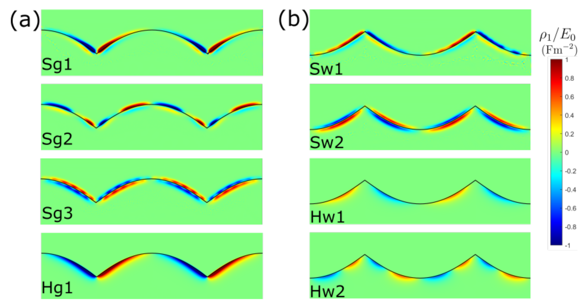
From reflection spectra, we notice an isolated peak (Sg3 or Sw2) in the case of SC-HD. These additional peaks are far from the mode discretized from the continuous mode in LRA. To understand the physics of the additional peak in the reflection spectrum of SC-HD case, we have compared the induced charge density distribution near the singular surface in Figure 4. In this figure, we give the induced charge distribution for all the marked peaks in Figure 3. Since the induced charge density for LRA is an infinite delta function, we therefore only show the distribution for SC-HD and HW-HD. For S-type peaks in both groove and wedge singular metasurfaces, the induced charge leaks out of the metal surface but with different patterns. Let us take the groove singular metasurface as an example, that is, Figure 4a, the Sg1 peak corresponds to the first-order surface plasmon mode, while the Sg2 is the second-order surface plasmon mode. These modes come from the discretization of the continuous mode Lg. We can tell that for Sg1 and Sg2, the induced charge near the interface is either primarily positive or primarily negative. These charge density profiles are similar to that of peak Hg1 of HW-HD. Although the induced charge is confined inside the metal surface for Hg1 mode, it is the same kind of surface plasmon mode as Sg1 and Sg2. However, the modes Sg1 and Sg2 differ from Hg1 in the centroid of induced charge density. From Figure 4a, we observe that for Sg1 and Sg2 the centroid of their induced charge density lies outside the jellium edge , while the absence of spill-out in Hg1 makes the centroid always inside the jellium edge. It is these spill-out and “spill-in” effects that lead to the different peak shiftings in the reflection spectrum. Likewise, in Figure 4b the spill-out of Sw1 mode and the spill-in of Hw1 and Hw2 modes makes the wedge singular metasurface exhibit a similar peak shifting behavior.
Special attention should be paid to the Sg3 mode in Figure 4a. From the charge profile, we can see that nearly the same amount of positive and negative charges on the two sides of the interface, which differs from that of Sg1 and Sg2 whose charge is dominated by either positive or negative charge. This additional mode is called Bennett mode, or multipole surface plasmon mode [29,33]. For traditional surface plasmon mode such as Sg1 and Sg2, the surface charge forms an effective monopole normal to the interface. However, for a multipole surface plasmon, an effective dipole forms normal to the interface. Therefore, the formation of a Bennett mode requires the spill-out of the electron at the metal interface, which explains why this multipole mode is absent in the HW-HD and LRA. Moreover, a similar Bennett mode is observed in Sw2 peak in wedge singular metasurface in Figure 4b. Similar to Sg3, induced electron for Sw2 mode also forms a dipole momentum normal to the interface.
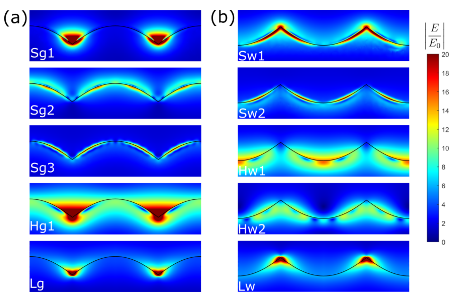
Finally, we illustrate the electric field enhancement of a singular metasurface for SC-HD, HW-HD and LRA in Figure 5. In our previous work, we show that the electric field enhancement of singular metasurface in the LRA case diverges as long as the vertex angle is larger than the critical angle [9,34]. For a LRA mode () in Figure 5a, the corresponding critical angle , making the electric field diverge at the terminal point. For a LRA mode () in Figure 5b, the critical angle , leading to a divergence of electric for a wedge singular metasurface.
Comparing LRA field with that of SC-HD and HW-HD in Figure 5, we conclude that the electric field in LRA is more localized at the sharp point. This delocalization is mainly attributed to the Pauli exclusion principle, that is, nonlocality, which hinders the localization of electrons to a very large density. This constraint leads the field enhancement of SC-HD and HW-HD to be finite and smaller than that of LRA case. Moreover, another comparison can be made between traditional surface plasmon mode and multipole surface plasmon mode. For Bennett mode in Figure 5 (Sg3 in the left panel or Sw2 in the right panel), we can observe that this multipole mode is highly localized at the interface, which means it shows a stronger decay normal to the interface compared with other traditional monopole surface plasmon modes. Note that in Figure 5 some modes exhibit maximum field enhancement at the cusp, while some are not. This is mainly because of different reflection phase at the cusp experienced by these surface plasmon modes [9,35].
4. Conclusions
In this paper, we consider the electron spill-out effect in the singular metasurface. The ground state calculation shows that our sharp singular point is effectively blunt. Besides, for the excited state, the introduction of the spill-out effect strongly changes the reflection spectrum, charge distribution and near-field profile. Therefore, it is vital to include this spill-out effect in the singular system, especially for a simple metal where the inter-band transition is absent. Finally, the electron spill-out calculation is still numerical in this paper, and an analytical approach of spill-out effect in the singular plasmonic system will be left to future work.
Author Contributions
F.Y. designed and performed research; F.Y. and K.D. analyzed data; F.Y. and K.D. wrote the paper. All authors have read and agreed to the published version of the manuscript.
Funding
This research was funded by Gordon and Betty Moore Foundation.
Data Availability Statement
The data that support the findings of this study are available from the corresponding author upon reasonable request.
Acknowledgments
Helpful discussions with J.B. Pendry are gratefully acknowledged. F.Y. acknowledges the Gordon and Betty Moore Foundation.
Conflicts of Interest
The authors declare no conflict of interest.
References
- Yu, N.; Capasso, F. Flat optics with designer metasurfaces. Nat. Mater. 2014, 13, 139–150. [Google Scholar] [CrossRef] [PubMed]
- Yu, N.; Genevet, P.; Kats, M.A.; Aieta, F.; Tetienne, J.P.; Capasso, F.; Gaburro, Z. Light propagation with phase discontinuities: Generalized laws of reflection and refraction. Science 2011, 334, 333–337. [Google Scholar] [CrossRef] [PubMed] [Green Version]
- Zhao, Y.; Alù, A. Manipulating light polarization with ultrathin plasmonic metasurfaces. Phys. Rev. B 2011, 84, 205428. [Google Scholar] [CrossRef]
- Yao, Y.; Shankar, R.; Kats, M.A.; Song, Y.; Kong, J.; Loncar, M.; Capasso, F. Electrically tunable metasurface perfect absorbers for ultrathin mid-infrared optical modulators. Nano Lett. 2014, 14, 6526–6532. [Google Scholar] [CrossRef]
- Azad, A.K.; Kort-Kamp, W.J.; Sykora, M.; Weisse-Bernstein, N.R.; Luk, T.S.; Taylor, A.J.; Dalvit, D.A.; Chen, H.T. Metasurface broadband solar absorber. Sci. Rep. 2016, 6, 1–6. [Google Scholar] [CrossRef] [PubMed]
- Aieta, F.; Genevet, P.; Kats, M.A.; Yu, N.; Blanchard, R.; Gaburro, Z.; Capasso, F. Aberration-free ultrathin flat lenses and axicons at telecom wavelengths based on plasmonic metasurfaces. Nano Lett. 2012, 12, 4932–4936. [Google Scholar] [CrossRef]
- Pors, A.; Nielsen, M.G.; Eriksen, R.L.; Bozhevolnyi, S.I. Broadband focusing flat mirrors based on plasmonic gradient metasurfaces. Nano Lett. 2013, 13, 829–834. [Google Scholar] [CrossRef] [PubMed]
- Pendry, J.; Huidobro, P.A.; Luo, Y.; Galiffi, E. Compacted dimensions and singular plasmonic surfaces. Science 2017, 358, 915–917. [Google Scholar] [CrossRef] [Green Version]
- Yang, F.; Huidobro, P.A.; Pendry, J.B. Transformation optics approach to singular metasurfaces. Phys. Rev. B 2018, 98, 125409. [Google Scholar] [CrossRef] [Green Version]
- Søndergaard, T.; Novikov, S.M.; Holmgaard, T.; Eriksen, R.L.; Beermann, J.; Han, Z.; Pedersen, K.; Bozhevolnyi, S.I. Plasmonic black gold by adiabatic nanofocusing and absorption of light in ultra-sharp convex grooves. Nat. Commun. 2012, 3, 1–6. [Google Scholar] [CrossRef] [PubMed] [Green Version]
- Raza, S.; Bozhevolnyi, S.I.; Wubs, M.; Mortensen, N.A. Nonlocal optical response in metallic nanostructures. J. Phys. Condens. Matter 2015, 27, 183204. [Google Scholar] [CrossRef] [Green Version]
- Zhu, W.; Esteban, R.; Borisov, A.G.; Baumberg, J.J.; Nordlander, P.; Lezec, H.J.; Aizpurua, J.; Crozier, K.B. Quantum mechanical effects in plasmonic structures with subnanometre gaps. Nat. Commun. 2016, 7, 1–14. [Google Scholar] [CrossRef]
- Kittel, C. Introduction to Solid State Physics, 8th ed.; Wiley: New York, NY, USA, 2005. [Google Scholar]
- Feibelman, P.J. Surface electromagnetic fields. Prog. Surf. Sci. 1982, 12, 287–407. [Google Scholar] [CrossRef]
- Scholl, J.A.; Koh, A.L.; Dionne, J.A. Quantum plasmon resonances of individual metallic nanoparticles. Nature 2012, 483, 421–427. [Google Scholar] [CrossRef] [PubMed]
- Savage, K.J.; Hawkeye, M.M.; Esteban, R.; Borisov, A.G.; Aizpurua, J.; Baumberg, J.J. Revealing the quantum regime in tunnelling plasmonics. Nature 2012, 491, 574–577. [Google Scholar] [CrossRef] [PubMed]
- Hohenberg, P.; Kohn, W. Inhomogeneous electron gas. Phys. Rev. 1964, 136, B864. [Google Scholar] [CrossRef] [Green Version]
- Kohn, W.; Sham, L.J. Self-consistent equations including exchange and correlation effects. Phys. Rev. 1965, 140, A1133. [Google Scholar] [CrossRef] [Green Version]
- Runge, E.; Gross, E.K. Density-functional theory for time-dependent systems. Phys. Rev. Lett. 1984, 52, 997. [Google Scholar] [CrossRef]
- Raza, S.; Toscano, G.; Jauho, A.P.; Wubs, M.; Mortensen, N.A. Unusual resonances in nanoplasmonic structures due to nonlocal response. Phys. Rev. B 2011, 84, 121412. [Google Scholar] [CrossRef] [Green Version]
- Ciracì, C.; Hill, R.; Mock, J.; Urzhumov, Y.; Fernández-Domínguez, A.; Maier, S.; Pendry, J.; Chilkoti, A.; Smith, D. Probing the ultimate limits of plasmonic enhancement. Science 2012, 337, 1072–1074. [Google Scholar] [CrossRef] [PubMed] [Green Version]
- Toscano, G.; Straubel, J.; Kwiatkowski, A.; Rockstuhl, C.; Evers, F.; Xu, H.; Mortensen, N.A.; Wubs, M. Resonance shifts and spill-out effects in self-consistent hydrodynamic nanoplasmonics. Nat. Commun. 2015, 6, 1–11. [Google Scholar] [CrossRef] [Green Version]
- Yan, W. Hydrodynamic theory for quantum plasmonics: Linear-response dynamics of the inhomogeneous electron gas. Phys. Rev. B 2015, 91, 115416. [Google Scholar] [CrossRef] [Green Version]
- Ciraci, C.; Della Sala, F. Quantum hydrodynamic theory for plasmonics: Impact of the electron density tail. Phys. Rev. B 2016, 93, 205405. [Google Scholar] [CrossRef] [Green Version]
- Ding, K.; Chan, C.T. Plasmonic modes of polygonal rods calculated using a quantum hydrodynamics method. Phys. Rev. B 2017, 96, 125134. [Google Scholar] [CrossRef] [Green Version]
- Fernández-Domínguez, A.; Wiener, A.; García-Vidal, F.; Maier, S.; Pendry, J. Transformation-optics description of nonlocal effects in plasmonic nanostructures. Phys. Rev. Lett. 2012, 108, 106802. [Google Scholar] [CrossRef] [PubMed] [Green Version]
- Luo, Y.; Fernandez-Dominguez, A.; Wiener, A.; Maier, S.A.; Pendry, J. Surface plasmons and nonlocality: A simple model. Phys. Rev. Lett. 2013, 111, 093901. [Google Scholar] [CrossRef] [Green Version]
- Yang, F.; Wang, Y.T.; Huidobro, P.A.; Pendry, J.B. Nonlocal effects in singular plasmonic metasurfaces. Phys. Rev. B 2019, 99, 165423. [Google Scholar] [CrossRef] [Green Version]
- Liebsch, A. Electronic Excitations at Metal Surfaces; Springer Science & Business Media: Berlin/Heidelberg, Germany, 2013. [Google Scholar]
- Lundqvist, S.; March, N.H. Theory of the Inhomogeneous Electron Gas; Springer Science & Business Media: Berlin/Heidelberg, Germany, 2013. [Google Scholar]
- Wigner, E. On the interaction of electrons in metals. Phys. Rev. 1934, 46, 1002. [Google Scholar] [CrossRef]
- AshcroftNeil, W.; Ashcroft, N.W.; Mermin, N.D.; Mermin, N.D. Solid State Physics; Cengage Learning: Boston, MA, USA, 1976; Volume 3. [Google Scholar]
- Bennett, A.J. Influence of the electron charge distribution on surface-plasmon dispersion. Phys. Rev. B 1970, 1, 203. [Google Scholar] [CrossRef]
- Luo, Y.; Pendry, J.; Aubry, A. Surface plasmons and singularities. Nano Lett. 2010, 10, 4186–4191. [Google Scholar] [CrossRef]
- Yang, F. The Study of Singular Plasmonic Metasurfaces with Transformation Optics. Ph.D. Thesis, Imperial College London, London, UK, 2019. [Google Scholar]
Figure 1.
Schematic for the paper. For singular metasurfaces, we have considered three different models: self-consistent hydrodynamic model (SC-HD); hard-wall hydrodynamic model (HW-HD); local-response approximation (LRA). is metal surface, is the equilibrium electron density, while is the induced electron density. Throughout this paper, the groove and wedge singular metasurfaces are considered, as shown in the upper left and lower left panel of the figure, respectively.

Figure 2.
Ground state calculation for singular metasurfaces with SC-HD. The contour plot shows the normalized equilibrium electron density, . (a) Groove singular metasurface; (b) Wedge singular metasurface.
Figure 2.
Ground state calculation for singular metasurfaces with SC-HD. The contour plot shows the normalized equilibrium electron density, . (a) Groove singular metasurface; (b) Wedge singular metasurface.

Figure 3.
Reflection of a singular metasurface according to SC-HD, HW-HD and LRA. The field excitation is a plane wave at normal incidence. (a) Groove singular metasurface with vertex angle rad; (b) Wedge singular metasurface with vertex angle rad; (c) Groove singular metasurface with vertex angle rad; (d) Wedge singular metasurface with vertex angle rad; (e) Groove singular metasurface with vertex angle rad; (f) Wedge singular metasurface with vertex angle rad.

Figure 4.
Induced charge distribution of singular metasurface ( rad) with SC-HD and HW-HD, which corresponds to the peak marked in Figure 3. (a) Groove case; (b) Wedge case. Note that is complex and that the real part is shown.
Figure 4.
Induced charge distribution of singular metasurface ( rad) with SC-HD and HW-HD, which corresponds to the peak marked in Figure 3. (a) Groove case; (b) Wedge case. Note that is complex and that the real part is shown.

Figure 5.
Electric field enhancement of singular metasurface ( rad) with SC-HD, HW-HD and LRA, which corresponds to the peak marked in Figure 3. (a) Groove case; (b) Wedge case. Note that the color function has been fixed as the same for all of contour plot so as to compare field enhancement properties. Besides, the electric field of LRA mode diverges at the singularity.

Publisher’s Note: MDPI stays neutral with regard to jurisdictional claims in published maps and institutional affiliations. |
© 2021 by the authors. Licensee MDPI, Basel, Switzerland. This article is an open access article distributed under the terms and conditions of the Creative Commons Attribution (CC BY) license (https://creativecommons.org/licenses/by/4.0/).
Share and Cite
MDPI and ACS Style
Yang, F.; Ding, K. Electron Spill-Out Effect in Singular Metasurfaces. Photonics 2021, 8, 154. https://0-doi-org.brum.beds.ac.uk/10.3390/photonics8050154
AMA Style
Yang F, Ding K. Electron Spill-Out Effect in Singular Metasurfaces. Photonics. 2021; 8(5):154. https://0-doi-org.brum.beds.ac.uk/10.3390/photonics8050154
Chicago/Turabian StyleYang, Fan, and Kun Ding. 2021. "Electron Spill-Out Effect in Singular Metasurfaces" Photonics 8, no. 5: 154. https://0-doi-org.brum.beds.ac.uk/10.3390/photonics8050154
Note that from the first issue of 2016, this journal uses article numbers instead of page numbers. See further details here.