
Operation of Large RF Driven Negative Ion Sources for Fusion at Pressures below 0.3 Pa


Max-Planck-Institut für Plasmaphysik, 85748 Garching, Germany
*
Author to whom correspondence should be addressed.
Plasma 2021, 4(1), 172-182; https://0-doi-org.brum.beds.ac.uk/10.3390/plasma4010010
Submission received: 13 January 2021
/
Revised: 28 January 2021
/
Accepted: 5 March 2021
/
Published: 9 March 2021
Abstract
:The large (size: 1 m × 2 m) radio frequency (RF) driven negative ion sources for the neutral beam heating (NBI) systems of the future fusion experiment ITER will be operated at a low filling pressure of 0.3 Pa, in hydrogen or in deuterium. The plasma will be generated by inductively coupling an RF power of up to 800 kW into the source volume. Under consideration for future neutral beam heating systems, like the one for the demonstration reactor DEMO, is an even lower filling pressure of 0.2 Pa. Together with the effect of neutral gas depletion, such low operational pressures can result in a neutral gas density below the limit required for sustaining the plasma. Systematic investigations on the low-pressure operational limit of the half-ITER-size negative ion source of the ELISE (Extraction from a Large Ion Source Experiment) test facility were performed, demonstrating that operation is possible below 0.2 Pa. A strong correlation of the lower pressure limit on the magnetic filter field topology is found. Depending on the field topology, operation close to the low-pressure limit is accompanied by strong plasma oscillations in the kHz range.
1. Introduction
The neutral beam heating (NBI) system of the international experimental reactor ITER will be based on large RF-driven sources for negative deuterium or hydrogen ions [1]. In order to provide the ion current needed for heating the ITER plasma and for current drive, 40 A accelerated to 1 MeV in deuterium and 46 A accelerated to 870 keV in hydrogen, the ion source has to be large: 1 m × 2 m with an extraction area of ≈0.2 m2 (1280 extraction apertures with a diameter of 14 mm each). A low-temperature plasma (Te ≈ 10 eV, ne ≈ 1018 m−3) is generated by inductive RF coupling (PRF up to 100 kW/driver, f = 1 MHz) into eight cylindrical RF drivers.
The source design based on several RF drivers is a modular one based on the RF-driven ITER prototype source [2] using one driver. This design was scaled up to the half-ITER-size ELISE ion source [2] and the full-size experiments SPIDER and MITICA [3], the latter being almost identical with the ion source to be used in the final ITER NBI beamline. The sources of the ITER NBI system will be operated at a filling pressure of 0.3 Pa in order to reduce the probability for negative ion destruction by stripping reactions with the background gas in the accelerator to about 30% [4,5]. A magnetic filter field with a strength of a few mT in the ion source volume close to the extraction system reduces the electron temperature and electron density to Te ≈ 1 eV, ne ≈ 1017 m−3, respectively [6]. Consequently, the probabilities for negative ion destruction by electron collisions [7] and the amount of co-extracted electrons are reduced [8].
Heating and current drive by NBI is under consideration also for the demonstration reactor DEMO [9,10]. While the wall-plug efficiency of the ITER NBI system will be ≈28% [11], for DEMO operating in steady state, a much higher wall-plug efficiency, up to ≈60% is envisaged [11]. In order to achieve this efficiency, different design modifications are necessary. For example, the concept of the gas neutralizer used at ITER has to be modified or replaced; for example, by a beam-driven plasma neutralizer [12,13,14]. Additionally, for further reducing the stripping losses, a filling pressure of 0.2 Pa instead of the 0.3 Pa used in ITER is under discussion [15]. The current European DEMO design is based on RF-driven ion sources similar to the ones used in ITER but with larger, racetrack-shaped RF drivers [11,12].
The plasma is generated in the RF drivers by electron impact ionisation [16], with a reaction probability proportional to the electron density, the background gas density and the respective ionisation rate coefficient. The RF power density coupled into the volume of the drivers is high, several kW per litre, resulting in an ionisation degree of about 10% [17]. The reduction from 0.3 to 0.2 Pa reduces the gas density in the drivers by approximately 30%. The low-pressure operational limit of a plasma source is defined by the gas density for which the number of ionising collisions in the plasma generation volume (by electron collision ionisation of the background gas) can just balance the losses of charged particles; in a low-pressure plasma, the latter mainly happens at the walls. If the pressure is too low, the plasma cannot be ignited or sustained. Neutral gas depletion [18], effectively reducing the gas pressure in the plasma generation volume for high power coupled into the plasma and a low gas flow [19,20], can thus strongly affect the low-pressure operational limit.
The following experimental and theoretical results indicate that the low-pressure operational limit of ion sources for NBI mainly depends on the strength and/or topology of the magnetic (filter) field, the source geometry and plasma parameters in the plasma generation volume. Since many NBI systems worldwide operate using arc-driven ion sources (see e.g., [21,22]), results from such sources are also mentioned here:
- An important factor is the strength of the magnetic field in the plasma generation region. For example, in the RF prototype source it is difficult to sustain the plasma if the magnetic field in the RF driver has a strength of more than ≈1 mT [6].
- The low-pressure operational limit correlates with the geometry of the ion source. Comparing results obtained at different arc driven ion sources, a general reduction of the low-pressure limit with an increasing ratio of the ion source volume to the plasma loss area is found [23]. This may indicate that racetrack-shaped RF drivers, as foreseen for the European DEMO, allow operation with lower filling pressures compared to circular drivers. Additionally, it was demonstrated that the minimum pressure is lower for the large RF-driven ELISE ion source where a higher gas flow is needed for a given pressure compared to the small RF prototype source [24].
- Modelling RF sources using a fluid code [25] points out that much higher electron energies are needed in the driver region for sustaining the plasma when the product of gas density times effective source dimension decreases below a certain threshold value; for the RF prototype source, this threshold is ≈2 × 10¹⁸ m−2.
Usually it is assumed that the average electron energy in the plasma generation region of arc-driven ion sources is higher than in RF sources (caused by the acceleration of primary electrons by a sheath of ≈60 V around the filaments [26]), and that thus arc sources are better suited for low-pressure operation. However, Langmuir probe measurements in the driver region of arc sources [27] and RF-driven sources [28] for a filling pressure of 0.3 Pa reveal a very similar structure of the electron energy distribution function: a low-energy component with Te,cold < 5 eV and a high energy component with Te,hot between 20 and 30 eV. Based on these results, the low-pressure operational limit should not depend on the mechanism of plasma generation but on physical factors like those defined above. Optical emission spectroscopy (OES), routinely applied for axial lines of sight through the driver region of RF sources, typically yield an averaged Te of about 10 eV [29].
One additional factor is the presence of caesium in the ion source plasma, used for reducing the work function of source surfaces close to the extraction system and thus to increase the negative ion production at these surfaces [30,31]. Due to its high mass and low electronegativity, an impact of the presence of caesium on general plasma properties and on the low-pressure operational limit cannot be excluded. Additionally, negative ions produced more effectively at the caesiated surfaces may play a role, because their presence can result in the formation of an electronegative plasma and thus strongly change the plasma behaviour.
Although the operation of the RF-driven prototype source was demonstrated for filling pressures down to ≈0.1 Pa [32], and similar values have been obtained using arc-driven sources [33], these results cannot be transferred directly to operation at ITER or at DEMO. The reason is that previous measurements have been done on ion sources that were significantly smaller than the ones foreseen for ITER and DEMO, using a non-ITER relevant topology of the magnetic fields and, in the case of the arc-driven source, for a reduced arc power. Additionally, most of these investigations have been done in hydrogen, i.e., due to the different mass, the gas flow has to be higher by a factor of approximately than in deuterium for achieving a specific filling pressure.
Experiments have been performed at the ELISE test facility with the aim of defining the low-pressure operational limit of RF-driven ion sources with a size close to that of the ITER source, ITER-relevant operational parameters and an ITER-relevant magnetic field topology. Investigations have been conducted for different topologies of the magnetic filter field in order to investigate its impact on the low-pressure operational limit.
2. The ELISE Test Facility
The ELISE test facility, using a half-ITER-size ion source (1 m × 1 m) [34], is an important intermediate step in the R&D roadmap for the development towards the negative ion sources for ITER NBI defined by the European domestic agency F4E [35,36].
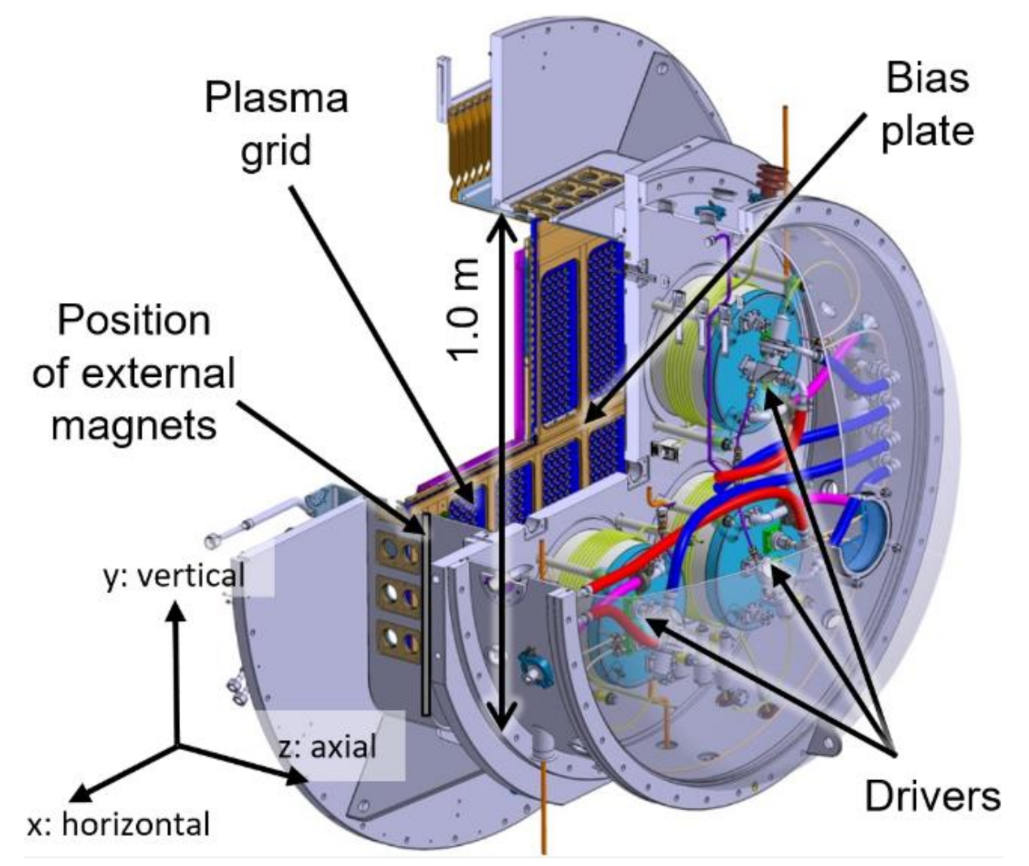
Figure 1 is a schematic overview of the ELISE ion source. Three of the four cylindrical RF drivers can be seen; each one is supplied with an RF power of up to 75 kW. Two RF generators are used, based on solid state amplifiers. The first generator supplies the upper pair of drivers, connected in series, and the second one the lower pair.
The plasma is cooled down from Te ≈ 10 eV (averaged, as described above) in the drivers to ≈1 eV in the expansion chamber close to the plasma grid (PG) [37] and attenuated (from ne ≈ 1018 m−3 to ≈1017 m−3) by a horizontal magnetic filter field with a strength of a few mT. This field strength is sufficient for magnetizing electrons but not the ions [6].
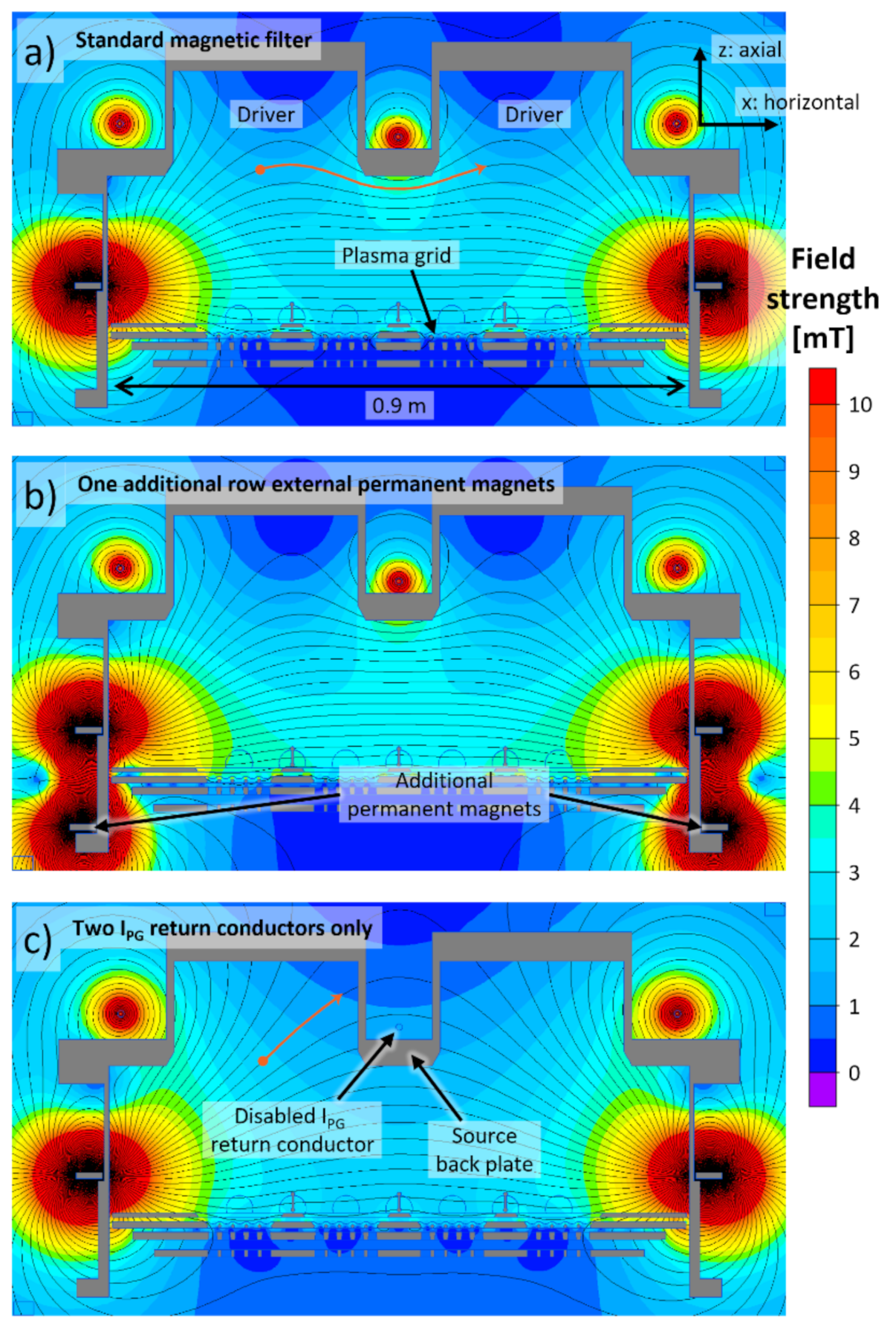
In the ELISE standard configuration, this magnetic filter is generated by a current IPG flowing vertically through the PG (usually IPG < 4 kA, corresponding to a filter field strength of 3.8 mT in two centimetres axial distance of the PG centre). The IPG return current is divided up evenly between three return conductors, located beside and between the drivers [38]. One row of external permanent magnets (CoSm, horizontal/axial/vertical cross section: 3.9 cm × 0.9 cm × 110 cm) attached to each of the vertical sidewalls in ≈7.5 cm axial distance to the PG [39] strengthens the IPG field by ≈ 0.4 mT. Figure 2a shows for this standard setup the 2D structure (calculated for a horizontal/axial cross section using the 2D code QuickField [40]) of the total filter field strength generated by IPG = 2.5 kA and the permanent magnets.
Located in 7 mm axial distance to the PG is the bias plate with window-frame-like openings around the beamlet groups (see Figure 1), divided into two horizontal segments. The bias plate is set to the electrostatic potential of the source body. The PG is positively biased, resulting in a reduction of the co-extracted electrons [41]. ELISE is operated in pulsed extraction mode; plasma pulses are possible up to one hour, with short extraction phases, so-called beam blips (length: 9.5 s; the shortest possible time between two blips is ≈150 s, limited by the available high voltage power supply). At the end of 2020, a continuous wave (CW) extraction power supply [42] will be commissioned.
3. Operation of the RF-Driven Source at Pressures below 0.3 Pa
3.1. Lowest Possible Operational Pressure
In order to determine the low-pressure operational limit, long plasma pulses (tplasma > 100 s) were done without beam extraction for an RF power of 60 kW/driver (which is slightly below the maximum available RF power). Up to now, no impact of beam extraction on the low-pressure operational limit has been observed. Detailed investigations on this topic will be possible with the new CW high voltage power supply. All investigations have been conducted with caesium present in the ion source, i.e., the plasma close to the PG can contain a significant number of negative ions. A similar series of experiments is planned to be conducted in a caesium-free source.
After the gas puff (pfill > 1 Pa), which is mandatory for plasma ignition [32], the filling pressure is first reduced to 0.35 Pa. This pressure is slightly higher than the usual filling pressure of ELISE (0.3 Pa, i.e., the ITER target value) in order to ensure plasma sustainment for all investigated filter topologies. Then, the low-pressure operational limit is identified by decreasing stepwise (Δp = 0.01 Pa, one pressure step each two to ten seconds) the filling pressure until plasma sustainment is no longer possible. Due to effects like neutral depletion, the pressure during the plasma-on time differs from the filling pressure and thus the pressure reduction is done by reducing the gas inflow into the ion source, based on a previously performed calibration of the filling pressure versus the gas inflow. The reproducibility of the performed pulses is very good and the error bar of the determined low-pressure operational limit can be assumed to be ± 0.01 Pa.
Due to the high relevance of deuterium operation for both ITER and DEMO, pulses are done in hydrogen and deuterium, with the ELISE standard magnetic filter (IPG plus one row of permanent magnets, three IPG return conductors, see Figure 2a) and with the following modifications of the field topology (individually and collectively) intended to affect the field topology in different regions of the ion source:
- A second row of external permanent magnets is added downstream the first row in 16 cm axial distance. This second row of magnets modifies the magnetic field lines mainly in close vicinity to the horizontal edges of the PG (see Figure 2b).
- The central IPG return conductor is disconnected, i.e., the IPG return current is distributed evenly between the two outermost return conductors. As illustrated in Figure 2c, this modification affects the magnetic field lines, the field gradients and locally also the field strength in the RF drivers and in the source volume close to them.
Additionally investigated is operation without the filter field by removing all external permanent magnets and switching off IPG.
Due to the typically higher amount of co-extracted electrons in deuterium than in hydrogen [2] and the stronger pronounced increase of these electrons with time [2], a higher IPG is used in deuterium (2.5 kA compared to 1.6 kA). For the standard setup of the magnetic filter (Figure 2a), this results in a field strength close to the centre of the PG of ≈1.9 mT in hydrogen and ≈2.8 mT in deuterium.
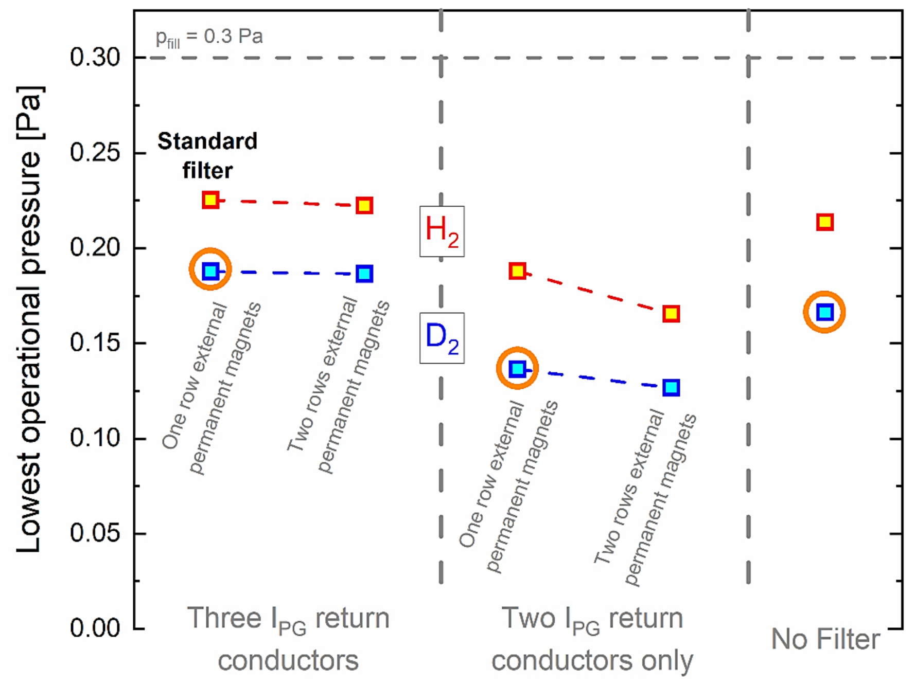
The low-pressure operational limit for the different filter configurations is summarised in Figure 3. The lowest operational pressure is ≈0.13 Pa in deuterium and ≈0.16 Pa in hydrogen (without the central IPG return conductor and with two rows of external permanent magnets). This difference is caused not by the different values of IPG used for hydrogen and deuterium but by the different gas flows: reducing for deuterium IPG to 1.6 kA, i.e., the value used for hydrogen, does not shift the low-pressure operational limit towards the results for hydrogen but causes even a very slight further reduction.
Operation without the central IPG return conductor has a significantly stronger effect on the lowest operational pressure than adding a second row of external permanent magnets. Without a filter field, the lowest operational pressure is reduced compared to the standard configuration, but only slightly. The observed minor role of the second row of permanent magnets demonstrates that the lowest operational pressure is affected only weakly by the magnetic field topology close to the PG. In contrast, the transport of charged particles in the driver or close to the driver—defined by the field topology and strength in this region—seems to be of high relevance.
Thus, further investigations are focussed on the three configurations indicated by the circles in Figure 3 in deuterium: the ELISE standard filter, the configuration without the central IPG return conductor and one row of external permanent magnets and the configuration without magnetic filter.
Close to the driver exit electrons are weakly magnetized (for Te = 10 eV and a field strength of 2 mT their gyro radius is approximately 5 mm). Thus, modifying the filter topology in this region directly affects the plasma transport towards the walls in the RF drivers and close to their exit. Additionally, the orientation of the field lines has an effect on plasma drifts. As shown in [43], the predominant drift close to the driver exit is the diamagnetic drift, mainly caused by gradients of the electron temperature. Electron temperature gradients are present mainly in axial direction [43], caused by the plasma expansion out of the drivers and by the electron cooling in the magnetic filter.
Disabling the central IPG return conductor drastically changes the orientation of the magnetic field lines in and close to the drivers (compare the orange lines in Figure 2a,c, starting from the identical position close to the driver exit and following the field), which may explain the lower possible operational pressure in this setup. In the standard configuration, the orientation of the field lines is much more perpendicular to the driver axis (and the assumed direction of the electron temperature gradients) than without the central IPG return conductor, i.e., the particle transport induced by the plasma drift points into a different direction. Additionally, the higher absolute magnetic field strength in the driver in the case of the disabled IPG return conductor compared to the standard case may play a role.
A full theoretical description of the interplay of the magnetic field topology with the plasma dynamics in and close to the RF drivers is mandatory for obtaining a full understanding of the physics responsible for the observations made. Such a description has to be performed in 3D and is possible, for example, by fluid models. Fluid code investigations performed up to now for negative ion sources for fusion [25,43] have been conducted in 2D only.
3.2. Plasma Oscillations at Low Operational Pressure
While due to the frequency of the RF generators (1 MHz) the plasma intrinsically oscillates in the MHz range, additional strong oscillations in the kHz range are observed for both hydrogen and deuterium in the signals of several diagnostics (mainly electrical measurements. A distinct disturbance is seen, for example, in the electron saturation branch of Langmuir probes, but also optical measurements like cavity ring-down spectroscopy [44] can be disturbed) for a filling pressure around or below 0.2 Pa.
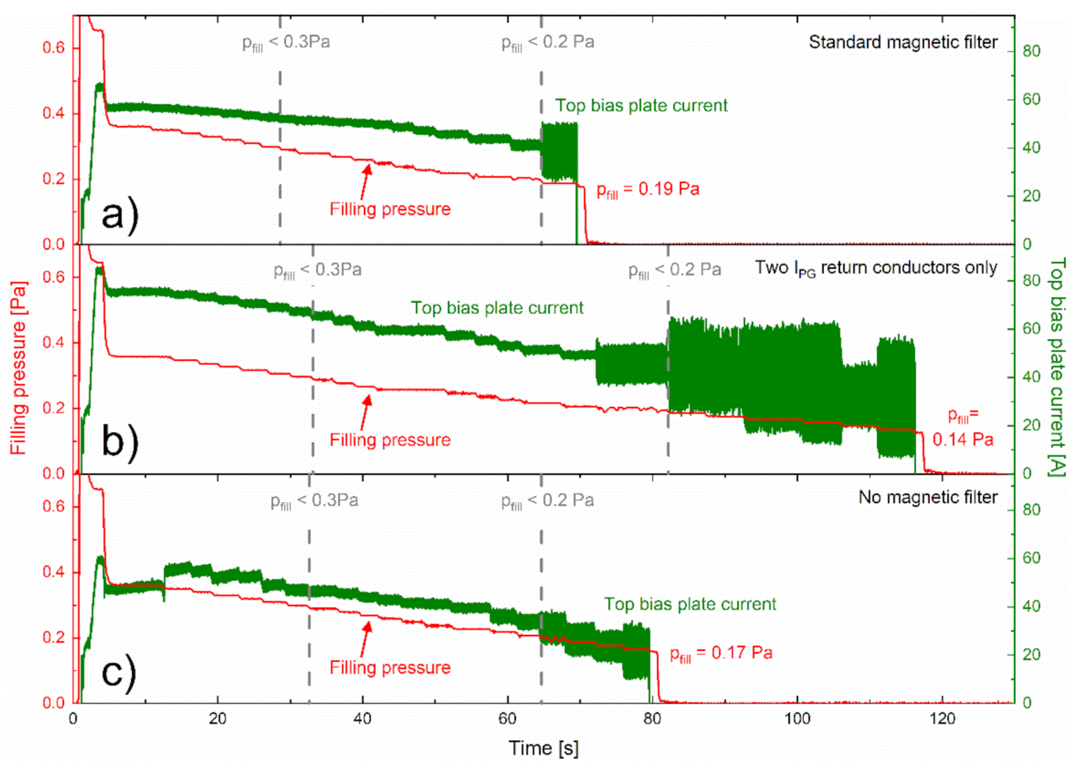
The onset and strength of these oscillations strongly depend on the topology of the magnetic filter, as illustrated in Figure 4 for deuterium, which shows for the ELISE standard filter, the configuration without the central IPG return conductors (and with one row of external permanent magnets) and the configuration without the magnetic filter time traces of the filling pressure and the current impinging the top segment of the bias plate. The latter is chosen as a measure for plasma oscillations because, due to its location close to the PG (see Figure 1) and its negative potential with respect to the PG, the bias plate acts as a kind of large planar probe for the average plasma density in the volume relevant for negative ion production and extraction. The combination of the used current transducer and the data acquisition system ensures that oscillations with a frequency of up to ≈1 kHz are directly visible in the measured bias plate current, and oscillations up to a few kHz can be seen as an increase in the noise level of the signal. The interplay of the used sensors with the data transmission and acquisition system results in a lower sampling rate of most of the other available measurements signals. Measuring selected plasma or beam properties with a sampling rate covering the kHz range is planned for the future.
Figure 4a shows results for deuterium with the standard filter, Figure 4b for the configuration without the central IPG return conductor and Figure 4c for operation without a filter field. In each case, for t < 6 s the gas puff and the following stepwise reduction of the filling pressure can be seen. The intrinsic noise of the measured bias plate current is ≈±1.5 A (for Ibias between 40 to 75 A, see Figure 4). Indicated by vertical dashed lines are the moments in time that the filling pressure is reduced to a value below 0.3 Pa and below 0.2 Pa. The diagnostics setup of ELISE does not currently allow any statements if the oscillations occur only close to the PG or in the whole source volume.
The only configuration for that operation at a filling pressure of 0.2 Pa that is possible without significant kHz oscillations is the standard filter. Operation both without the filter and with the modified field topology caused by disabling the central IPG return conductor result in the occurrence of kHz oscillations at a filling pressure slightly above 0.2 Pa. In parallel, the low-pressure operational range is significantly extended (see Figure 3). These observations are generally valid, also for operation in hydrogen and with the second row of external permanent magnets.
The oscillation amplitude reaches up to ≈±30 A (for Ibias ≈ 40 A, see Figure 4). How these oscillations correlate to oscillations in the general plasma properties or the generation of negative ions at the PG surface and on their transport through the plasma cannot be measured due to a too low sampling rate of the available negative ion current diagnostics. However, an effect on the extracted negative hydrogen ion current and thus on the beam divergence (coupled to the extracted current via the perveance [45]) cannot be excluded. Therefore, prior to the application of an ion source in this extended low-pressure regime to NBI systems, these oscillations and their impact on the beam optics has to be investigated carefully; for example, using a fast beamlet monitor [46].
In the standard filter configuration, the magnetic field lines directly connect the plasma close to the exit of horizontally neighbouring drivers, which is not the case when disabling the central IPG return conductor. This is again illustrated by the orange lines in Figure 2a,c. Without a filter field, the electrons are not magnetised. Consequently, also in this case the connection between the plasma from the two drivers is weak. This strongly reduced connection between the drivers in the cases without the central return conductor and without a filter field may be correlated to the appearance of the kHz oscillations at a low filling pressure.
The beat frequency of the two used 1 MHz solid state generators is in the kHz range but is not solely responsible for the observed oscillations. Dedicated experiments revealed that the frequency of the kHz oscillations does react only weakly on tuning (in steps of 1 kHz) the frequency difference of the generators in a broad range and they cannot be completely removed even when matching the externally measured frequencies of both generators.
Other potential physical effects behind the observed oscillations are turbulent plasma transport through the magnetic filter, possibly in interplay with electric fields close to the PG, i.e., drift induced effects or attachment-induced ionisation instabilities [47,48]. Turbulent transport of electrons through a magnetic field and a way to remove this turbulence by an admixture of nitrogen gas has been described in [49] for a compact surface plasma source for negative ions, but for neutral gas densities and magnetic field strength that are significantly higher than what is present in the ELISE ion source. The mechanism behind attachment-induced ionisation instabilities in the latter process is that in electronegative plasmas, small instabilities in the electron density and the electron temperature can shift the rates for creation and destruction of charged particle species in a way that amplifies the initial instability and thus results in a strong plasma oscillation. The relevance of attachment-induced ionisation instabilities strongly depends on the gas species and on the plasma parameters. In the negative ion sources under investigation, this effect may be relevant in the plasma close to the PG when caesium is present in the source. Detailed investigations on this mechanism are in preparation, combining measurements with higher sampling rates with theoretical studies.
Again, a full 3D theoretical description is desirable for obtaining a deeper insight into the physics involved. Although the results of some codes indicate the presence of oscillations in general, these oscillations are either in the MHz range (1D PIC code [50]) or are enhanced by the fact that the code cannot properly describe the electron transport perpendicular to the magnetic filter (2D fluid code [25]). Several different 3D particle in cell codes [20,51,52] exist describing the ion source or a plasma volume in it, but up to now pronounced kHz oscillations have not been identified in the results of these codes. No 3D fluid code for the plasma of fusion-relevant negative ion sources exists.
4. Conclusions
The RF-driven large negative ion source ELISE can be operated at a filling pressure of ≈0.2 Pa under discussion for DEMO. Further decreasing the pressure can cause issues regarding the sustainment and stability of the plasma. The onset of observed oscillations in the kHz range and the low-pressure operational RF limit strongly depend on the magnetic field topology. In particular the magnetic field in or close to the drivers plays a crucial role, most probably by its direct impact on the transport and the drift of magnetized charged particles. As a theoretical description of these oscillations is not yet available, the results presented within this paper are intended to motivate theoretical investigations and to define some of the needed input parameters.
It has to be kept in mind that the possibility to generate a plasma at 0.2 Pa does not necessarily mean that a high extracted negative ion current density can be achieved for such low pressures. For both RF- and arc-driven ion sources, the amount of co-extracted electrons strongly increases when reducing the filling pressure, in particular in deuterium [2]. Additionally, the typically observed increase in time of these co-extracted electrons gets much steeper when reducing the filling pressure [41], which is of particular importance for DEMO where pulse lengths of up to 7200 s are envisaged [12]. It may be possible to solve these issues by introducing alternative caesium evaporation concepts, e.g., evaporating caesium very close to the plasma grid [53].
Alternative geometries of the ion source or the RF driver, like the racetrack-shaped RF drivers used in the current European DEMO design, may have an effect on the low-pressure operational limit. Thus, currently planned experiments using a racetrack driver at ELISE [11], following successful initial tests of this type of RF driver performed at the smaller prototype source [54], are of high relevance for DEMO.
Author Contributions
Conceptualization, D.W., R.R., M.F., U.F. and B.H.; formal analysis, D.W.; investigation, D.W. and R.R.; writing—original draft preparation, D.W.; writing—review and editing, D.W., R.R., M.F., U.F. and B.H.; visualization, D.W. and M.F.; project administration, D.W., U.F. and B.H.; funding acquisition, U.F. and B.H.; All authors have read and agreed to the published version of the manuscript.
Funding
Funded by EUROFusion, grant number 633053.
Institutional Review Board Statement
Not applicable.
Informed Consent Statement
Not applicable.
Data Availability Statement
The data presented in this study are available on request from the authors.
Acknowledgments
This work has been carried out within the framework of the EUROfusion Consortium and has received funding from the Euratom research and training programme 2014–2018 and 2019–2020 under grant agreement No 633053. The views and opinions expressed herein do not necessarily reflect those of the European Commission. The authors wish to thank Andrew Hurlbatt for discussions on the different possible mechanisms that could cause oscillations in electronegative plasmas.
Conflicts of Interest
The authors declare no conflict of interest.
References
- Hemsworth, R.S.; Boilson, D.; Blatchford, P.; Dalla Palma, M.; Chitarin, G.; Esch, H.P.L.; Geli, F.; Dremel, M.; Graceffa, J.; Marcuzzi, D. Overview of the design of the ITER heating neutral beam injectors. New J. Phys. 2017, 19, 025005. [Google Scholar] [CrossRef]
- Heinemann, B.; Fantz, U.; Kraus, W.; Schiesko, L.; Wimmer, C.; Wünderlich, D.; Bonomo, F.; Fröschle, M.; Nocentini, R.; Riedl, R. Towards large and powerful radio frequency driven negative ion sources for fusion. New J. Phys. 2017, 19, 015001. [Google Scholar] [CrossRef]
- Toigo, V.; Piovan, R.; Dal Bello, S.; Gaio, E.; Luchetta, A.; Pasqualotto, R.; Zaccaria, P.; Bigi, M.; Chitarin, G.; Marcuzzi, D.; et al. The PRIMA Test Facility: SPIDER and MITICA test-beds for ITER neutral beam injectors. New J. Phys. 2017, 19, 085004. [Google Scholar] [CrossRef] [Green Version]
- Hemsworth, R.; Decamps, H.; Graceffa, J.; Schunke, B.; Tanaka, M.; Dremel, M.; Tanga, A.; De Esch, H.P.L.; Geli, F.; Milnes, J.; et al. Status of the ITER heating neutral beam system. Nucl. Fusion 2009, 49, 045006. [Google Scholar] [CrossRef] [Green Version]
- Krylov, A.; Hemsworth, R. Gas flow and related beam losses in the ITER neutral beam injector. Fusion Eng. Des. 2006, 81, 2239. [Google Scholar] [CrossRef]
- Fantz, U.; Schiesko, L.; Wünderlich, D. Plasma expansion across a transverse magnetic field in a negative hydrogen ion source for fusion. Plasma Sources Sci. Technol. 2014, 23, 044002. [Google Scholar] [CrossRef]
- Fantz, U.; Falter, H.D.; Franzen, P.; Wünderlich, D.; Berger, M.; Lorenz, A.; Kraus, W.; Mcneely, P.; Riedl, R.; Speth, E. Spectroscopy—A powerful diagnostic tool in source development. Nucl. Fusion 2006, 46, S297. [Google Scholar] [CrossRef] [Green Version]
- Franzen, P.; Schiesko, L.; Fröschle, M.; Wünderlich, D.; Fantz, U.; NNBI-Team. Magnetic Filter Field Dependence of the Performance of the RF Driven IPP Prototype Source for Negative Hydrogen Ions. Plasma Phys. Control. Fusion 2011, 53, 115006. [Google Scholar] [CrossRef] [Green Version]
- Zohm, H. On the Minimum Size of DEMO. Fusion Sci. Technol. 2017, 58, 613. [Google Scholar] [CrossRef]
- Federici, G.; Biel, W.; Gilbert, M.R.; Kemp, R.; Taylor, N.; Wenninger, R. European DEMO design strategy and consequences for materials. Nucl. Fusion 2017, 57, 092002. [Google Scholar] [CrossRef] [Green Version]
- Fantz, U.; Hopf, C.; Friedl, R.; Cristofaro, S.; Heinemann, B.; Lishev, S.; Mimo, A. Technology developments for a beam source of an NNBI system for DEMO. Fusion Eng. Des. 2018, 136, 340. [Google Scholar] [CrossRef] [Green Version]
- Agostinetti, P.; Franke, T.; Fantz, U.; Hopf, C.; Mantel, N.; Tran, M.Q. RAMI evaluation of the beam source for the DEMO neutral beam injectors. Fusion Eng. Des. 2020, 159, 111628. [Google Scholar] [CrossRef]
- Surrey, E.; Holmes, A. The beam driven plasma neutralizer. AIP Conf. Proc. 2013, 1515, 532. [Google Scholar]
- Turner, I.; Holmes, A.J.T. Model for a beam driven plasma neutraliser based on ITER beam geometry. Fusion Eng. Des. 2019, 149, 111327. [Google Scholar] [CrossRef]
- Sonato, P.; Agostinetti, P.; Fantz, U.; Franke, T.; Furno, I.; Simonin, A.; Tran, M.Q. Conceptual design of the beam source for the DEMO Neutral Beam Injectors. New J. Phys. 2016, 18, 125002. [Google Scholar] [CrossRef] [Green Version]
- Faircloth, D.; Lawrie, S. An overview of negative hydrogen ion sources for accelerators. New J. Phys. 2018, 20, 025007. [Google Scholar] [CrossRef] [Green Version]
- Fantz, U.; Wünderlich, D. A novel diagnostic technique for H-(D-) densities in negative hydrogen ion sources. New J. Phys. 2006, 8, 301. [Google Scholar] [CrossRef]
- Fruchtman, A. Neutral gas depletion in low temperature plasma. J. Phys. D 2017, 50, 473002. [Google Scholar] [CrossRef] [Green Version]
- Mcneely, P.; Wünderlich, D.; The NNBI-Team. Neutral depletion in an H- source operated at high RF power and low input gas flow. Plasma Sources Sci. Technol. 2011, 20, 045005. [Google Scholar] [CrossRef]
- Fubiani, G.; Garrigues, L.; Hagelaar, G.J.M.; Kohen, N.; Boeuf, J.P. Modeling of plasma transport and negative ion extraction in a magnetized radio-frequency plasma source. New J. Phys. 2017, 19, 015002. [Google Scholar] [CrossRef]
- Tsumori, K.; Ikeda, K.; Nakano, H.; Kisaki, M.; Geng, S.; Wada, M.; Sasaki, K.; Nishiyama, S.; Goto, M.; Serianni, G.; et al. Negative ion production and beam extraction processes in a large ion source (invited). Rev. Sci. Instrum. 2016, 87, 02B936. [Google Scholar] [CrossRef] [PubMed] [Green Version]
- Kojima, A.; Hiratsuka, J.; Umeda, N.; Hanada, M.; Kashiwagi, M.; Yoshida, M.; Ichikawa, M.; Nishikiori, R.; Watanabe, K.; Tobari, H.; et al. Development of long-pulse high-power-density negative ion beams with a multi-aperture multi-grid accelerator. Fusion Eng. Des. 2017, 123, 236. [Google Scholar] [CrossRef]
- Inoue, T.; Hemsworth, R.; Kulygin, V.; Okumura, Y. ITER R&D: Auxiliary Systems: Neutral Beam Heating and Current Drive System. Fusion Eng. Des. 2001, 55, 291. [Google Scholar]
- Franzen, P.; Heinemann, B.; Fantz, U.; Wünderlich, D.; Kraus, W.; Fröschle, M.; Martens, C.; Riedl, R.; Nocentini, R.; Masiello, A.; et al. Commissioning and first results of the ITER-relevant negative ion beam test facility ELISE. Fusion Eng. Des. 2013, 88, 3132. [Google Scholar] [CrossRef] [Green Version]
- Boeuf, J.P.; Hagelaar, G.J.M.; Sarrailh, P.; Fubiani, G.; Kohen, N. Model of an inductively coupled negative ion source: II. Application to an ITER type source. Plasma Sources Sci. Technol. 2011, 20, 015002. [Google Scholar] [CrossRef]
- Hanada, M.; Seki, T.; Takado, N.; Inoue, T.; Mizuno, T.; Hatayama, A.; Kashiwagi, M.; Sakamoto, K.; Taniguchi, M.; Watanabe, K. The origin of beam non-uniformity in a large Cs-seeded negative ion source. Nucl. Fusion 2006, 46, S318. [Google Scholar] [CrossRef]
- Takado, N.; Tobari, H.; Inoue, T.; Hanatani, J.; Hatayama, A.; Hanada, M.; Kashiwagi, M.; Sakamoto, K. Numerical analysis of the production profile of H0 atoms and subsequent H− ions in large negative ion sources. J. Appl. Phys. 2008, 103, 053302. [Google Scholar] [CrossRef]
- Mcneely, P.; Dudin, S.V.; Christ-Koch, S.; Fantz, U. A Langmuir probe system for high power RF-driven negative ion sources on high potential. Plasma Sources Sci. Technol. 2009, 18, 014011. [Google Scholar] [CrossRef]
- Briefi, S.; Fantz, U. Spectroscopic investigations of the ion source at BATMAN upgrade. AIP Conf. Proc. 2018, 2052, 040005. [Google Scholar]
- Belchenko, Y.; Dimov, G.I.; Dudnikov, V.G. A powerful injector of neutrals with a surfaceplasma source of negative ions. Nucl. Fusion 1974, 14, 113. [Google Scholar] [CrossRef]
- Dudnikov, V. Development and Applications of Negative Ion Sources; Springer: Cham, Switzerland, 2019. [Google Scholar]
- Speth, E.; Falter, H.D.; Franzen, P.; Fantz, U.; Bandyopadhyay, M.; Christ, S.; Encheva, A.; Fröschle, M.; Holtum, D.; Heinemann, B.; et al. Overview of the RF source development programme at IPP Garching. Nucl. Fusion 2006, 46, S220. [Google Scholar] [CrossRef] [Green Version]
- Tsumori, K.; Nakano, H.; Kisaki, M.; Ikeda, K.; Nagaoka, K.; Osakabe, M.; Takeiri, Y.; Kaneko, O.; Shibuya, M.; Asano, E.; et al. Spatial distribution of the charged particles and potentials during beam extraction in a negative-ion source. Rev. Sci. Instrum. 2012, 83, 02B116. [Google Scholar] [CrossRef]
- Heinemann, B.; Falter, H.D.; Fantz, U.; Franzen, P.; Fröschle, M.; Kraus, W.; Martens, C.; Nocentini, R.; Riedl, R.; Speth, E. The negative ion source test facility ELISE. Fusion Eng. Des. 2011, 86, 768. [Google Scholar] [CrossRef]
- Masiello, A.; Agarici, G.; Bonicelli, T.; Simon, M.; Antoni, V.; De Esch, H.P.L.; De Lorenzi, A.; Dremel, M.; Franzen, P.; Hemsworth, R.; et al. European programme towards the 1 MeV ITER NB injector. Fusion Eng. Des. 2009, 84, 1276. [Google Scholar] [CrossRef]
- Masiello, A.; Agarici, G.; Bonicelli, T.; Fantini, F.; Gagliardi, M.; Paolucci, M.; Simon, M.; Wikus, P.; Agostinetti, P.; Bigi, M.; et al. Symmetries and Asymmetries in the Divertor Detachment in ASDEX Upgrade. In Proceedings of the 24th IAEA Fusion Energy Conference, San Diego, CA, USA, 8–13 October 2012. [Google Scholar]
- Schiesko, L.; Mcneely, P.; Franzen, P.; Fantz, U.; NNBI-Team. Magnetic field dependence of the plasma properties in a negative hydrogen ion source for fusion. Plasma Phys. Control. Fusion 2012, 54, 105002. [Google Scholar] [CrossRef]
- Fröschle, M.; Fantz, U.; Franzen, P.; Kraus, W.; Nocentini, R.; Schiesko, L.; Wünderlich, D.; NNBI-Team. Magnetic filter field for ELISE—Concepts and design. Fusion Eng. Des. 2013, 88, 1015. [Google Scholar] [CrossRef] [Green Version]
- Wünderlich, D.; Kraus, W.; Fröschle, M.; Riedl, R.; Fantz, U.; Heinemann, B.; NNBI-Team. Influence of the magnetic field topology on the performance of the large area negative hydrogen ion source test facility ELISE. Plasma Phys. Control. Fusion 2016, 58, 125005. [Google Scholar] [CrossRef]
- Tera Analysis Ltd. QuickField: A New Approach to Field Modeling. Available online: https://quickfield.com/ (accessed on 8 March 2021).
- Franzen, P.; Fantz, U.; Wünderlich, D.; Heinemann, B.; Riedl, R.; Kraus, W.; Fröschle, M.; Ruf, B.; Nocentini, R.; NNBI-Team. Progress of the ELISE test facility: Results of caesium operation with low RF power. Nucl. Fusion 2015, 55, 053005. [Google Scholar] [CrossRef]
- Nocentini, R.; Fantz, U.; Fröschle, M.; Heinemann, B.; Kraus, W.; Riedl, R.; Wünderlich, D. Preparation of the ELISE test facility for long-pulse extraction of negative ion beams. Fusion Eng. Des. 2017, 123, 263. [Google Scholar] [CrossRef]
- Lishev, S.; Schiesko, L.; Wünderlich, D.; Wimmer, C.; Fantz, U. Fluid-model analysis on discharge structuring in the RF-driven prototype ion-source for ITER NBI. Plasma Sources Sci. Technol. 2018, 27, 125008. [Google Scholar] [CrossRef]
- Mimo, A.; Nakano, H.; Wimmer, C.; Wünderlich, D.; Fantz, U.; Tsumori, K. Cavity ring-down spectroscopy system for the evaluation of negative hydrogen ion density at the ELISE test facility. Rev. Sci. Instrum. 2020, 91, 013510. [Google Scholar] [CrossRef]
- Coupland, J.R.; Green, T.S.; Hammond, D.P.; Riviere, A.C. A Study of the Ion Beam Intensity and Divergence Obtained from a Single Aperture Three Electrode Extraction System. Rev. Sci. Instrum. 1973, 44, 1258. [Google Scholar] [CrossRef]
- Haba, Y.; Nagaoka, K.; Tsumori, K.; Kisaki, M.; Nakano, H.; Ikeda, K.; Fujiwara, Y.; Kamio, S.; Yoshimura, S.; Osakabe, M. Development of a dual beamlet monitor system for negative ion beam measurements. Rev. Sci. Instrum. 2018, 89, 123303. [Google Scholar] [CrossRef] [PubMed] [Green Version]
- Nighan, W.L.; Wiegand, W.J. Influence of negative-ion processes on steady-state properties and striations in molecular gas discharges. Phys. Rev. A 1974, 10, 922. [Google Scholar] [CrossRef]
- Descoeudres, A.; Sansonnens, L.; Hollenstein, C. Attachment-induced ionization instability in electronegative capacitive RF discharges. Plasma Sources Sci. Technol. 2003, 12, 152. [Google Scholar] [CrossRef]
- Dudnikov, V.; Bollinger, D.; Faircloth, D.; Lawrie, S. Potential for improving of the compact surface plasma sources. AIP Conf. Proc. 2013, 1515, 369. [Google Scholar]
- Boeuf, J.P.; Chaudhury, B.; Garrigues, L. Physics of a magnetic filter for negative ion sources. I. Collisional transport across the filter in an ideal, 1D filter. Phys. Plasmas 2012, 19, 113509. [Google Scholar] [CrossRef]
- Mochalskyy, S.; Fantz, U.; Wünderlich, D.; Minea, T. Comparison of ONIX simulation results with experimental data from the BATMAN testbed for the study of negative ion extraction. Nucl. Fusion 2016, 56, 106025. [Google Scholar] [CrossRef] [Green Version]
- Taccogna, F.; Minelli, P. PIC modeling of negative ion sources for fusion. New J. Phys. 2017, 19, 015012. [Google Scholar] [CrossRef] [Green Version]
- Mimo, A.; Wimmer, C.; Wünderlich, D.; Fantz, U. Studies of the Cs Dynamics in Large Ion Sources using the CsFlow3D Code. AIP Conf. Proc. 2018, 2052, 040009. [Google Scholar]
- Kraus, W.; Schiesko, L.; Wimmer, C.; Fantz, U.; Heinemann, B. Performance of the BATMAN RF source with a large racetrack shaped driver. AIP Conf. Proc. 2017, 1869, 030006. [Google Scholar]
Figure 1.
Schematic view of the ELISE ion source with three of the four RF drivers, the bias plate and the plasma grid. Additionally, indicated for one of the vertical sidewalls is the position of the respective row of external permanent magnets.
Figure 1.
Schematic view of the ELISE ion source with three of the four RF drivers, the bias plate and the plasma grid. Additionally, indicated for one of the vertical sidewalls is the position of the respective row of external permanent magnets.

Figure 2.
2D structure (horizontal/axial cross section) of the field strength for three different topologies of the ELISE magnetic filter. (a) the standard filter, (b) one additional row of external permanent magnets and (c) only two IPG return conductors. The orange lines illustrate the strong effect of disconnecting the central IPG return conductor on the field topology in and close to the RF drivers.

Figure 3.
Lowest operational pressure of the ELISE ion source for different topologies of the magnetic filter field. The configurations indicated by the circles are investigated in more detail. The dashed horizontal line illustrates the filling pressure foreseen for the ITER neutral beam heating (NBI) ion sources.

Figure 4.
Time traces of the filling pressure and the current flowing onto the top segment of the bias plate when approaching in deuterium the low-pressure operational limit for three different magnetic filter topologies: (a) the standard setup, (b) using two IPG return conductors only and (c) without a magnetic filter.

Publisher’s Note: MDPI stays neutral with regard to jurisdictional claims in published maps and institutional affiliations. |
© 2021 by the authors. Licensee MDPI, Basel, Switzerland. This article is an open access article distributed under the terms and conditions of the Creative Commons Attribution (CC BY) license (http://creativecommons.org/licenses/by/4.0/).
Share and Cite
MDPI and ACS Style
Wünderlich, D.; Riedl, R.; Fröschle, M.; Fantz, U.; Heinemann, B. Operation of Large RF Driven Negative Ion Sources for Fusion at Pressures below 0.3 Pa. Plasma 2021, 4, 172-182. https://0-doi-org.brum.beds.ac.uk/10.3390/plasma4010010
AMA Style
Wünderlich D, Riedl R, Fröschle M, Fantz U, Heinemann B. Operation of Large RF Driven Negative Ion Sources for Fusion at Pressures below 0.3 Pa. Plasma. 2021; 4(1):172-182. https://0-doi-org.brum.beds.ac.uk/10.3390/plasma4010010
Chicago/Turabian StyleWünderlich, Dirk, Rudi Riedl, Markus Fröschle, Ursel Fantz, and Bernd Heinemann. 2021. "Operation of Large RF Driven Negative Ion Sources for Fusion at Pressures below 0.3 Pa" Plasma 4, no. 1: 172-182. https://0-doi-org.brum.beds.ac.uk/10.3390/plasma4010010