
Is Micro X-ray Computer Tomography a Suitable Non-Destructive Method for the Characterisation of Dental Materials?

 ,
,  and
and
Abstract
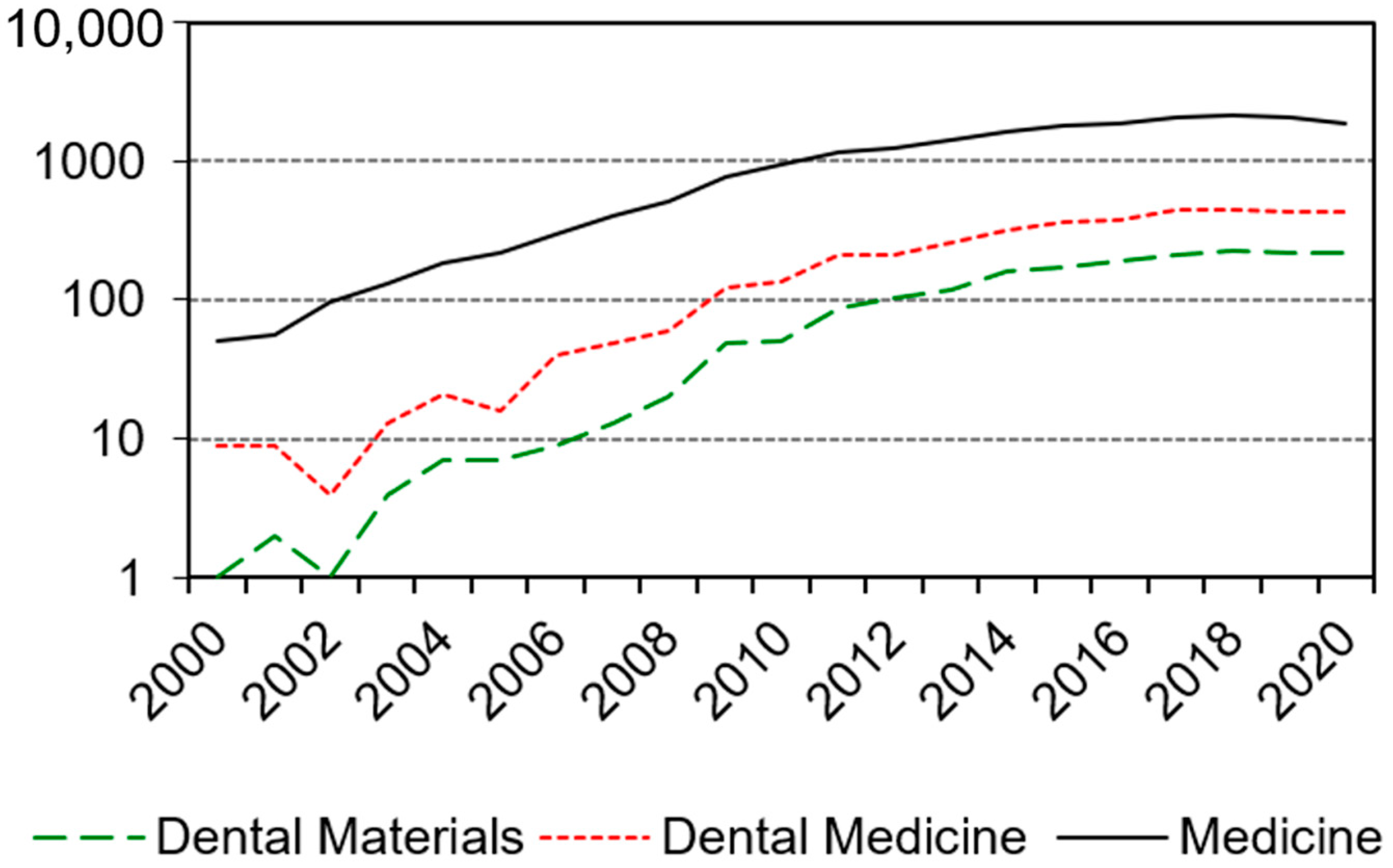
:1. Introduction
- ▪
- Enamel thickness measurement and tooth characterisation.
- ▪
- Analysis of root canals.
- ▪
- Craniofacial skeletal development and structure.
- ▪
- Analysis of biomechanical behaviour (in combination with finite element modelling (FEM)).
- ▪
- Tissue engineering.
- ▪
- Quantification of mineral concentration in teeth.
- ▪
- Implant and peri-implant bone analysis.
2. Materials, Preparation and Methods
2.1. Materials
2.2. Preparation
2.3. Methods
2.3.1. Differential Scanning Calorimetry (DSC)
2.3.2. Micro X-ray Computed Tomography (µXCT)
2.3.3. Mechanical Tests
3. Results
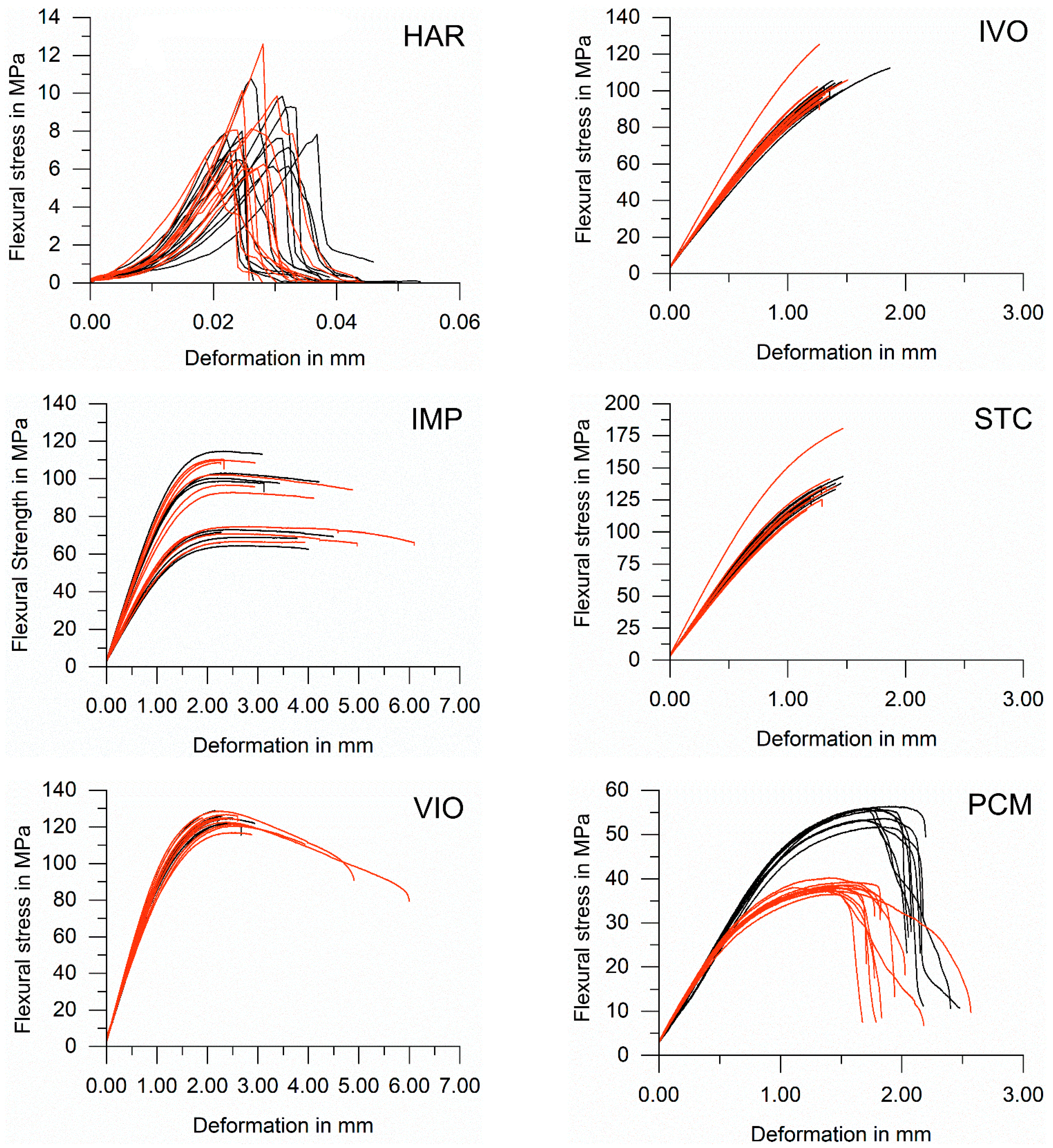
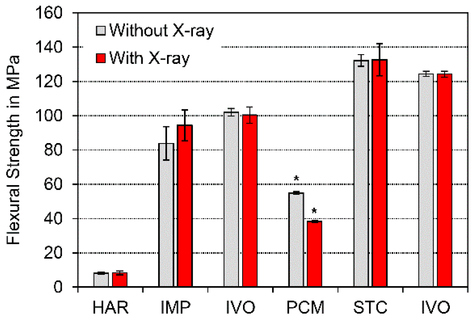
3.1. Flexural Strength
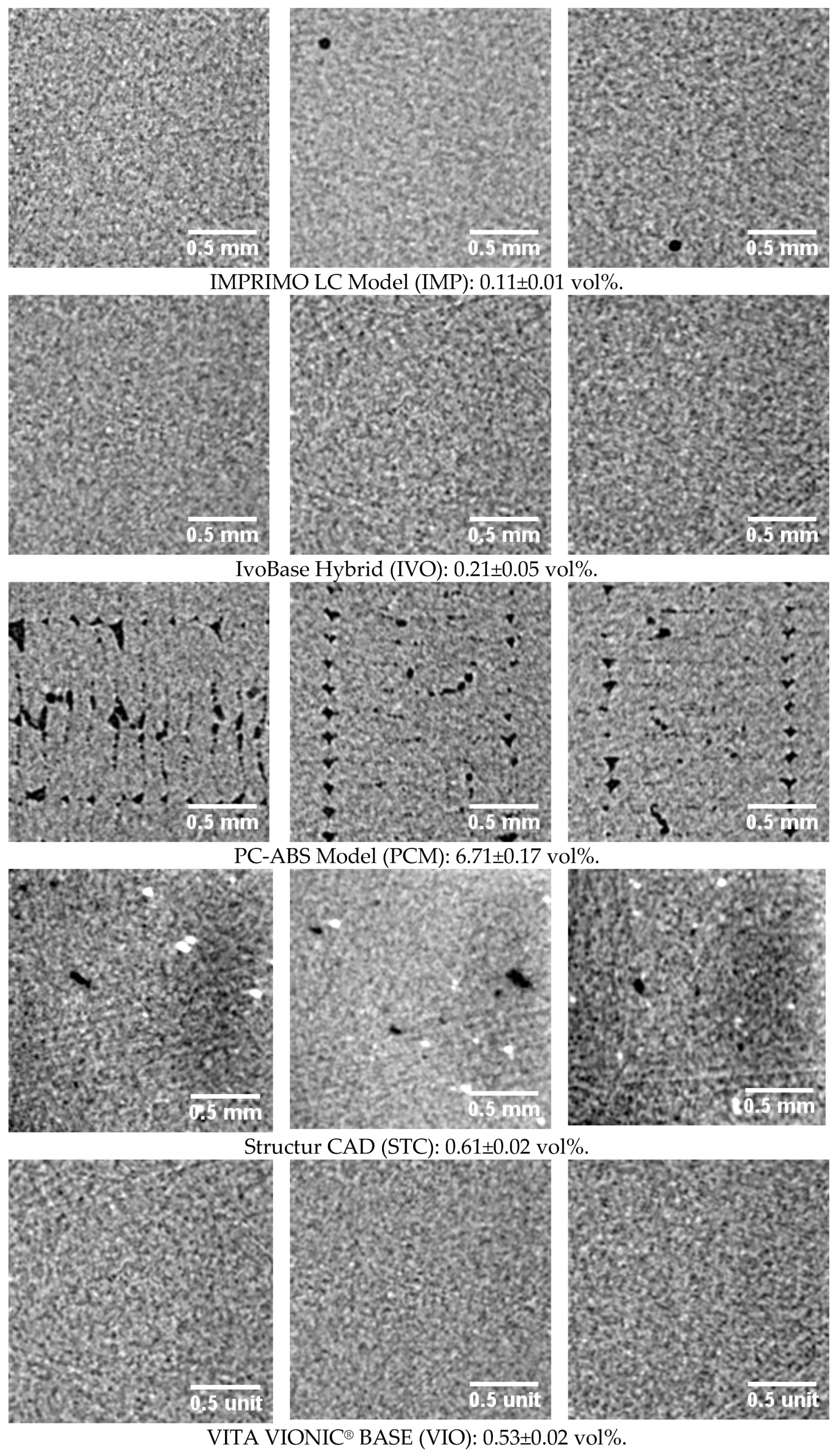
3.2. Microstructure
3.3. Changes in the Internal Structure of the Materials
4. Discussion
4.1. Harvard Cement (HAR)
4.2. PC-ABS Model Material (PCM)
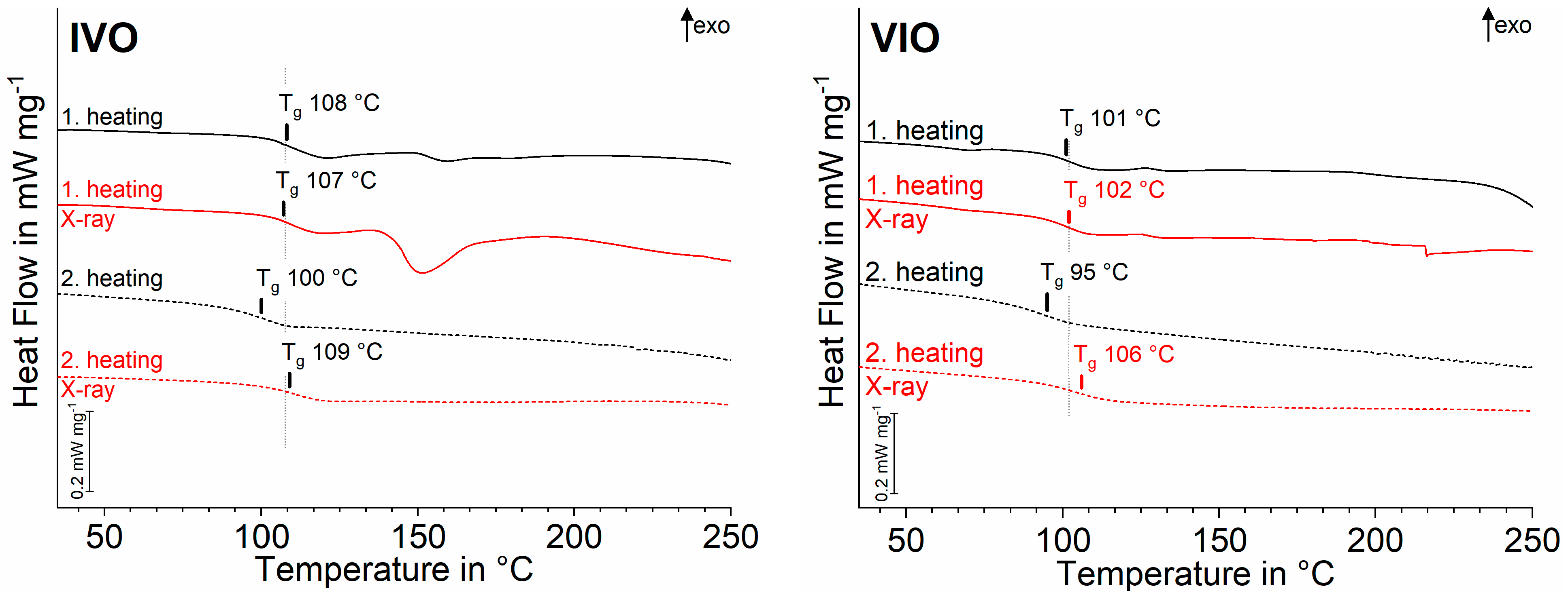
4.3. Poly(methyl methacrylate) (IVO, VIO)
- ▪
- a combination of chain breakage and cross-linking was induced by X-ray irradiation, but did not have a relevant impact on Tg in DSC curves of first heating (nor mechanics).
- ▪
- during the first heating, loose ends of broken chains previously caused by X-ray irradiation reconnected.
4.4. Resin-Based Composite (STC)
4.5. Resume
- (1)
- The influence of X-ray radiation during µXCT measurement has to be verified beforehand for each polymer type.
- (2)
- The X-ray tube output and the measurement time have to be limited.
5. Summary
- (1)
- A significant change in flexural strength due to X-ray irradiation during a single µXCT measurement occurred only with polycarbonate with acrylnitril-butadien-styrol (PC-ABS). No changes were detected in zinc phosphate cement (Harvard Cement), poly(methyl methacrylate) (PMMA), methacrylate, or other resin-based composites (RBCs).
- (2)
- A shift in glass transition (Tg) in both PMMA samples after repeated heating indicates a slight change in temperature resistance. The temperature resistance could be the result of degradation of the polymer network, e.g., main chain cleavages, which are re-cross-linked by repeated heating.
- (3)
- Further studies are necessary to investigate the influence of X-rays during µXCT measurements on the composition and performance of materials.
Author Contributions
Funding
Institutional Review Board Statement
Informed Consent Statement
Data Availability Statement
Acknowledgments
Conflicts of Interest
Appendix A

| Code | Radiation | Temperatures in °C and Assignment | |||||||||
|---|---|---|---|---|---|---|---|---|---|---|---|
| HAR | O | 146 | endo peak | 177 | endo peak | 302 | endo peak | ||||
| X | 121 | endo peak | 304 | endo peak | |||||||
| IMP | O | 62 | endo peak | 232 | exo peak | 296 | exo peak | ||||
| X | 61 | endo peak | 237 | exo peak | 291 | exo peak | |||||
| IVO | O | 108 | Tg PMMA | 159 | endo peak | ||||||
| X | 107 | Tg PMMA | 151 | endo peak | |||||||
| PCM | O | 47 | endo peak | 105 | Tg SAN | 130 | Tg PC | 236 | exo peak | 361 | exo peak |
| X | 47 | endo peak | 106 | Tg SAN | 129 | Tg PC | 236 | exo peak | 359 | exo peak | |
| STC | O | 257 | exo peak | ||||||||
| X | 268 | exo peak | |||||||||
| VIO | O | 67 | endo peak | 101 | Tg PMMA | 126 | exo peak | ||||
| X | 102 | Tg PMMA | 125 | exo peak | |||||||
References
- Swain, M.V.; Xue, J. State of the art of Micro-CT applications in dental research. Int. J. Oral Sci. 2009, 1, 177–188. [Google Scholar] [CrossRef]
- Bianco, E.; Calvelli, C.; Citterio, C.L.; Pellegatta, A.; Venino, P.M.; Maddalone, M. Evaluation with Micro-CT of the Canal Seal Made with Two Different Bioceramic Cements: GuttaFlow Bioseal and BioRoot RCS. J. Contemp. Dent. Pract. 2020, 21, 359–366. [Google Scholar] [PubMed]
- Nilsen, B.W.; Mouhat, M.; Jokstad, A. Quantification of porosity in composite resins delivered by injectable syringes using X-ray microtomography. Biomater. Investig. Dent. 2020, 7, 86–95. [Google Scholar] [CrossRef] [PubMed]
- Koenig, A.; Schmidtke, J.; Schmohl, L.; Schneider-Feyrer, S.; Rosentritt, M.; Hoelzig, H.; Kloess, G.; Vejjasilpa, K.; Schulz-Siegmund, M.; Fuchs, F.; et al. Characterisation of the filler fraction in CAD/CAM resin-based composites. Materials 2021, 14. accepted. [Google Scholar]
- Kaisarly, D.; Gezawi, M.E. Polymerization shrinkage assessment of dental resin composites: A literature review. Odontology 2016, 104, 257–270. [Google Scholar] [CrossRef] [PubMed]
- Sampaio, C.S.; Fernández Arias, J.; Atria, P.J.; Cáceres, E.; Pardo Díaz, C.; Freitas, A.Z.; Hirata, R. Volumetric polymerization shrinkage and its comparison to internal adaptation in bulk fill and conventional composites: A μCT and OCT in vitro analysis. Dent. Mater. 2019, 35, 1568–1575. [Google Scholar] [CrossRef] [PubMed]
- Ersen, K.A.; Gürbüz, Ö.; Özcan, M. Evaluation of polymerization shrinkage of bulk-fill resin composites using microcomputed tomography. Clin. Oral Investig. 2020, 24, 1687–1693. [Google Scholar] [CrossRef] [PubMed]
- Soares, C.J.; Rosatto, C.; Carvalho, V.F.; Bicalho, A.A.; Henriques, J.; Faria-E-Silva, A.L. Radiopacity and Porosity of Bulk-fill and Conventional Composite Posterior Restorations-Digital X-ray Analysis. Oper. Dent. 2017, 42, 616–625. [Google Scholar] [CrossRef] [PubMed]
- Van Ende, A.; van de Casteele, E.; Depypere, M.; de Munck, J.; Li, X.; Maes, F.; Wevers, M.; van Meerbeek, B. 3D volumetric displacement and strain analysis of composite polymerization. Dent. Mater. 2015, 31, 453–461. [Google Scholar] [CrossRef] [PubMed]
- Takemura, Y.; Hanaoka, K.; Kawamata, R.; Sakurai, T.; Teranaka, T. Three-dimensional X-ray micro-computed tomography analysis of polymerization shrinkage vectors in flowable composite. Dent. Mater. J. 2014, 33, 476–483. [Google Scholar] [CrossRef] [Green Version]
- Harada, A.; Nakamura, K.; Kanno, T.; Inagaki, R.; Örtengren, U.; Niwano, Y.; Sasaki, K.; Egusa, H. Fracture resistance of computer-aided design/computer-aided manufacturing-generated composite resin-based molar crowns. Eur. J. Oral Sci. 2015, 123, 122–129. [Google Scholar] [CrossRef] [Green Version]
- Ashfaq, A.; Clochard, M.-C.; Coqueret, X.; Dispenza, C.; Driscoll, M.S.; Ulański, P.; Al-Sheikhly, M. Polymerization Reactions and Modifications of Polymers by Ionizing Radiation. Polymers 2020, 12, 2877. [Google Scholar] [CrossRef] [PubMed]
- Buonocore, M. Adhesive sealing of pits and fissures for caries prevention, with use of ultraviolet light. J. Am. Dent. Assoc. 1970, 80, 324–330. [Google Scholar] [CrossRef] [PubMed]
- Santini, A.; Gallegos, I.T.; Felix, C.M. Photoinitiators in dentistry: A review. Prim. Dent. J. 2013, 2, 30–33. [Google Scholar] [CrossRef] [PubMed]
- Koizumi, H.; Okamura, K.; Hiraba, H.; Kodaira, A.; Yoneyama, T.; Matsumura, H. Radiopacity of computer-aided design/computer-aided manufacturing composite resin blocks. Eur. J. Oral Sci. 2020, 128, 241–245. [Google Scholar] [CrossRef] [PubMed]
- Behr, M.; Rosentritt, M.; Faltermeier, A.; Handel, G. Electron beam irradiation of dental composites. Dent. Mater. 2005, 21, 804–810. [Google Scholar] [CrossRef] [PubMed]
- Faltermeier, A.; Behr, M.; Rosentritt, M.; Handel, G. Electron-beam irradiation of experimental denture base polymers. Acta Odontol. Scand. 2007, 65, 171–176. [Google Scholar] [CrossRef]
- Da Cruz, A.D.; Sinhoreti, M.A.C.; Ambrosano, G.M.; Rastelli, A.N.d.S.; Bagnato, V.S.; Bóscolo, F.N. Effect of therapeutic dose X rays on mechanical and chemical properties of esthetic dental materials. Mater. Res. 2008, 11, 313–318. [Google Scholar] [CrossRef] [Green Version]
- E Lima, R.B.W.; de Vasconcelos, L.C.; Pontual, M.L.; Meireles, S.S.; Maciel Andrade, A.K.; Duarte, R.M. Effect of ionizing radiation on the properties of restorative materials. Indian J. Dent. Res. 2019, 30, 408–413. [Google Scholar] [CrossRef]
- Beste, D. Strahlenvernetzung Veredelt Polymere für den Effizienteren Kunststoffeinsatz. Available online: https://www.ingenieur.de/technik/fachbereiche/verfahrenstechnik/strahlenvernetzung-veredelt-polymere-fuer-effizienteren-kunststoffeinsatz/ (accessed on 21 March 2021).
- Dehn, F.; Thalheim, S.; Koenig, A. Betontechnologische Maßnahmen gegen Brandeinwirkungen. In Proceedings of the 13th Symposium Baustoffe und Bauwerkserhaltung, Karlsruhe, Germany, 16 March 2017. [Google Scholar] [CrossRef]
- Zhao, S.; Kramer, H.M.; Hohlfeld, K. The Yield from X Ray Tubes in Terms of Ambient Dose Equivalent. Radiat. Prot. Dosim. 1994, 51, 297–300. [Google Scholar] [CrossRef]
- Koenig, A. Analysis of air voids in cementitious materials using micro X-ray computed tomography (µXCT). Constr. Build. Mater. 2020, 244, 118313. [Google Scholar] [CrossRef]
- Jabri, M.; Mejdoubi, E.; El Gadi, M.; Hammouti, B. Hydratation mechanism of a zinc phosphate cement and development of its mechanical profile. Res. Chem. Intermed. 2013, 39, 3117–3126. [Google Scholar] [CrossRef]
- Romanova, N.; Shafigullin, L.; Gabdrakhmanov, A.; Buyatova, S. Thermal properties of products based on ABS / PC. MATEC Web Conf. 2019, 298, 16. [Google Scholar] [CrossRef]
- Aid, S.; Eddhahak, A.; Ortega, Z.; Froelich, D.; Tcharkhtchi, A. Experimental study of the miscibility of ABS/PC polymer blends and investigation of the processing effect. J. Appl. Polym. Sci. 2017, 134. [Google Scholar] [CrossRef]
- Ehrenstein, G.W.; Riedel, G.; Trawiel, P. Praxis der Thermischen Analyse von Kunststoffe; 2., völlig überarb. Aufl.; Hanser: Munich, Germany, 2003; ISBN 978-3446223400. [Google Scholar]
- Wang, L.; Liang, T. Ceramics for high level radioactive waste solidification. J. Adv. Ceram. 2012, 1, 194–203. [Google Scholar] [CrossRef] [Green Version]
- Nasdala, L.; Akhmadaliev, S.; Burakov, B.E.; Chanmuang, N.C.; Škoda, R. The absence of metamictisation in natural monazite. Sci. Rep. 2020, 10, 14676. [Google Scholar] [CrossRef] [PubMed]
- Brandel, V.; Dacheux, N.; Genet, M. Studies on the chemistry of uranium and thorium phosphates. Thorium phosphate diphosphate: A matrix for storage of radioactive wastes. Radiochemistry 2001, 43, 16–23. [Google Scholar] [CrossRef]
- Popescu, D.; Baciu, F.; Vlăsceanu, D.; Cotruţ, C.M.; Marinescu, R. Effects of multiple sterilizations and natural aging on the mechanical behavior of 3D-printed ABS. Mech. Mater. 2020, 148, 103423. [Google Scholar] [CrossRef]
- Ramezani Dana, H.; Barbe, F.; Delbreilh, L.; Azzouna, M.B.; Guillet, A.; Breteau, T. Polymer additive manufacturing of ABS structure: Influence of printing direction on mechanical properties. J. Manuf. Process. 2019, 44, 288–298. [Google Scholar] [CrossRef]
- Andreas, B.; Breunig, I.; Buse, K. Modeling of X-ray-induced refractive index changes in poly(methyl methacrylate). ChemPhysChem 2005, 6, 1544–1553. [Google Scholar] [CrossRef] [PubMed]
- Domininghaus, H.; Elsner, P.; Eyerer, P.; Hirth, T. Kunststoffe: Eigenschaften und Anwendungen; 8., neu Bearbeitete und Erweiterte Auflage; Springer: Berlin/Heidelberg, Germany, 2012; ISBN 978-3-642-16173-5. [Google Scholar]
- Wady, P.; Wasilewski, A.; Brock, L.; Edge, R.; Baidak, A.; McBride, C.; Leay, L.; Griffiths, A.; Vallés, C. Effect of ionising radiation on the mechanical and structural properties of 3D printed plastics. Addit. Manuf. 2020, 31, 100907. [Google Scholar] [CrossRef]
- Choi, J.O. Degradation of poly(methylmethacrylate) by deep ultraviolet, x-ray, electron beam, and proton beam irradiations. J. Vac. Sci. Technol. B 1988, 6, 2286. [Google Scholar] [CrossRef]
- Moore, J.A.; Choi, J.O. Degradation of Poly(methyl methacrylate). In Radiation Effects on Polymers; Clough, R.L., Shalaby, S.W., Eds.; American Chemical Society: Washington, DC, USA, 1991; pp. 156–192. ISBN 0-8412-2165-0. [Google Scholar]
- Yates, B.W.; Shinozaki, D.M. Radiation degradation of poly(methyl methacrylate) in the soft x-ray region. J. Polym. Sci. B Polym. Phys. 1993, 31, 1779–1784. [Google Scholar] [CrossRef]
- Fox, T.G.; Flory, P.J. Second-Order Transition Temperatures and Related Properties of Polystyrene. I. Influence of Molecular Weight. J. Appl. Phys. 1950, 21, 581–591. [Google Scholar] [CrossRef]
- Rouif, S. Radiation cross-linked polymers: Recent developments and new applications. Nucl. Instrum. Methods Phys. Res. Sect. B 2005, 236, 68–72. [Google Scholar] [CrossRef]
- Wondraczek, K.; Adams, J.; Fuhrmann, J. Effect of Thermal Degradation on Glass Transition Temperature of PMMA. Macromol. Chem. Phys. 2004, 205, 1858–1862. [Google Scholar] [CrossRef]
- Menyhárd, A.; Menczel, J.D.; Abraham, T. Polypropylene fibers. Thermal Analysis of Textiles and Fibers; Elsevier: Amsterdam, The Netherlands, 2020; pp. 205–222. ISBN 9780081005729. [Google Scholar]
- Rauch, A.; Koenig, A. Indirekte Komposite aus klinischer und werkstoffkundlicher Sicht. Quintessenz 2020, 71, 116–126. [Google Scholar]


| Code | Product Name | Manufacturer | Processing Type | Lot | Composition |
|---|---|---|---|---|---|
| HAR | Harvard Cement Normal setting | Harvard Dental International GmbH | Powder Liquid | 91706641 | Zinc phosphate cement |
| IMP | IMPRIMO LC Model | Scheu Dental GmbH | 3D Printing | 4118A | Methacrylate-based resin |
| IVO | IvoBase Hybrid | Ivoclar Vivadent AG | Powder Liquid | YT1269 | Poly(methyl methacrylate) (PMMA) |
| PCM | PC-ABS Model Material | Stratasys Ltd. | 3D Printing | - 1 | Polycarbonate with acrylonitrile-butadiene-styrene (PC-ABS) |
| STC | Structur CAD | VOCO GmbH | Milling | 1942209 | Resin-based Composite |
| VIO | VITA VIONIC® BASE | VITA Zahnfabrik H. Rauter GmbH & Co. KG | Milling | 76380 | Poly(methyl methacrylate) (PMMA) |
| Measurement Settings | ||
|---|---|---|
| Specimen | Geometry | 12 beams radially arranged on a carbon tube |
| Focus–object distance (FOD) | 150 mm | |
| X-ray | Voltage | 140 kV |
| Current | 140 µA | |
| Detector | Filter | - |
| Exposure time per position | 0.999 ms | |
| Positions | 0.45°/360° 800 images | |
| Resolution | Voxel size | 8.3 µm edge length 572 µm3 |
| Units | Mineral-Based HAR | Polymer-Based IVO, PCM, STC, VIO | |
|---|---|---|---|
| Support distance | mm | 10 | 20 |
| Approach speed | mm/min | 2.00 | 7.50 |
| Pre-load | N | 0.1 | 1.0 |
| Loading speed | mm/min | 0.75 | 0.75 |
Publisher’s Note: MDPI stays neutral with regard to jurisdictional claims in published maps and institutional affiliations. |
© 2021 by the authors. Licensee MDPI, Basel, Switzerland. This article is an open access article distributed under the terms and conditions of the Creative Commons Attribution (CC BY) license (https://creativecommons.org/licenses/by/4.0/).
Share and Cite
Koenig, A.; Schmohl, L.; Scheffler, J.; Fuchs, F.; Schulz-Siegmund, M.; Doerfler, H.-M.; Jankuhn, S.; Hahnel, S. Is Micro X-ray Computer Tomography a Suitable Non-Destructive Method for the Characterisation of Dental Materials? Polymers 2021, 13, 1271. https://0-doi-org.brum.beds.ac.uk/10.3390/polym13081271
Koenig A, Schmohl L, Scheffler J, Fuchs F, Schulz-Siegmund M, Doerfler H-M, Jankuhn S, Hahnel S. Is Micro X-ray Computer Tomography a Suitable Non-Destructive Method for the Characterisation of Dental Materials? Polymers. 2021; 13(8):1271. https://0-doi-org.brum.beds.ac.uk/10.3390/polym13081271
Chicago/Turabian StyleKoenig, Andreas, Leonie Schmohl, Johannes Scheffler, Florian Fuchs, Michaela Schulz-Siegmund, Hans-Martin Doerfler, Steffen Jankuhn, and Sebastian Hahnel. 2021. "Is Micro X-ray Computer Tomography a Suitable Non-Destructive Method for the Characterisation of Dental Materials?" Polymers 13, no. 8: 1271. https://0-doi-org.brum.beds.ac.uk/10.3390/polym13081271