
Investigating the Dimensional Accuracy of the Cavity Produced by ABS P400 Polymer-Based Novel EDM Electrode

 ,
,
Abstract
:
1. Introduction
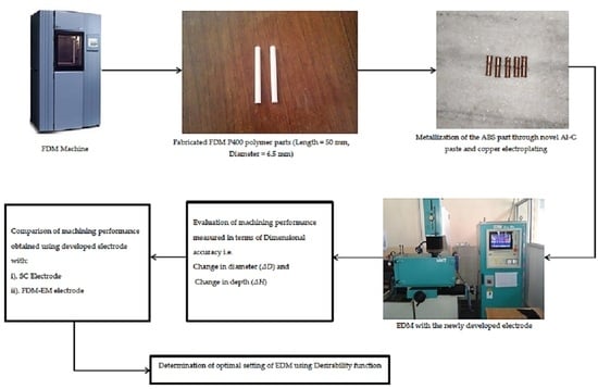
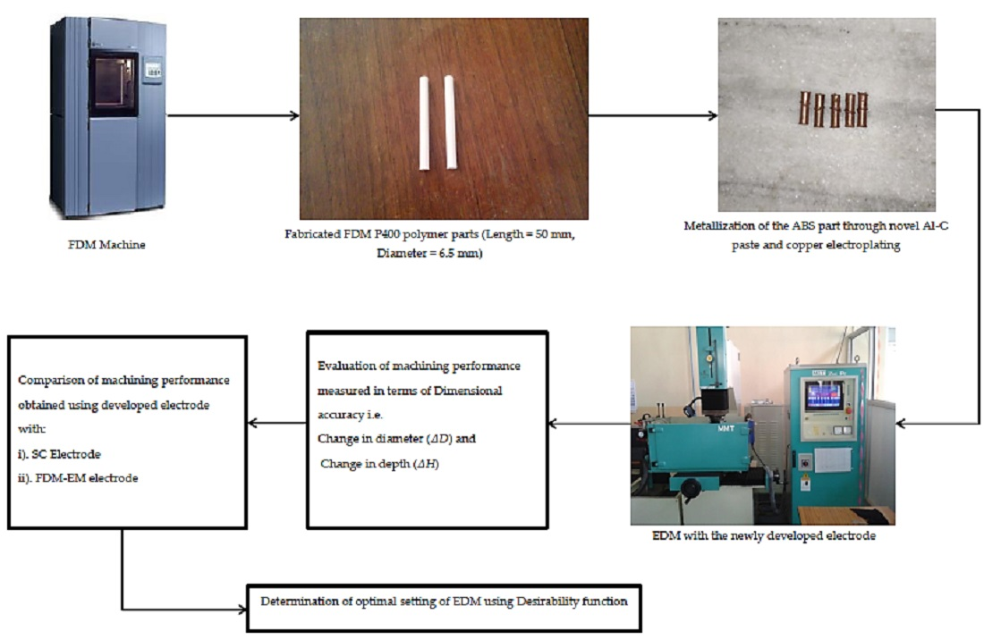
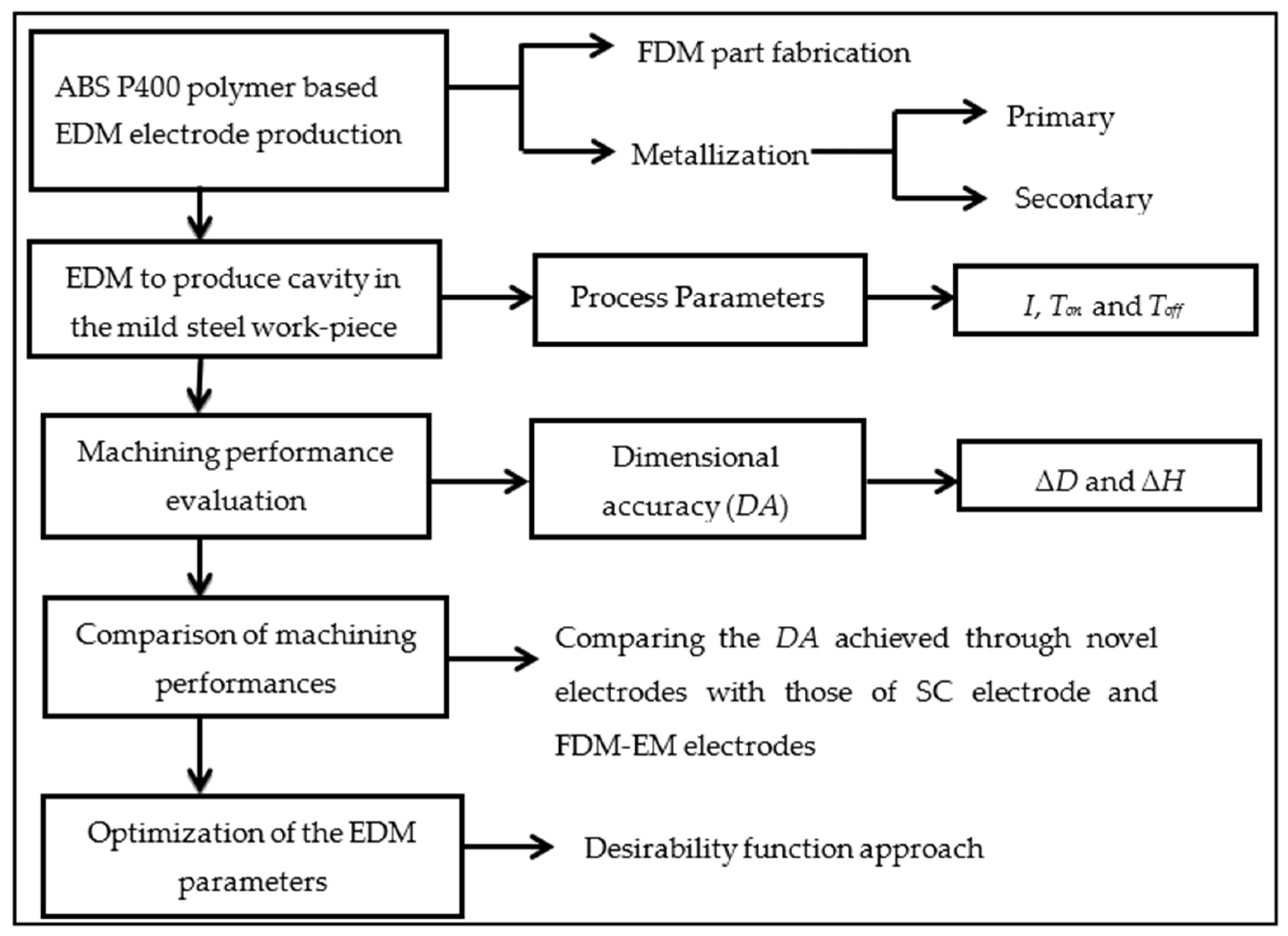
2. Methodology
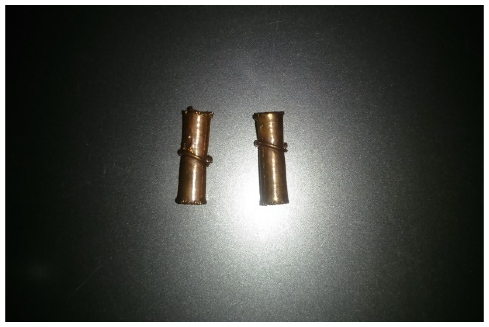
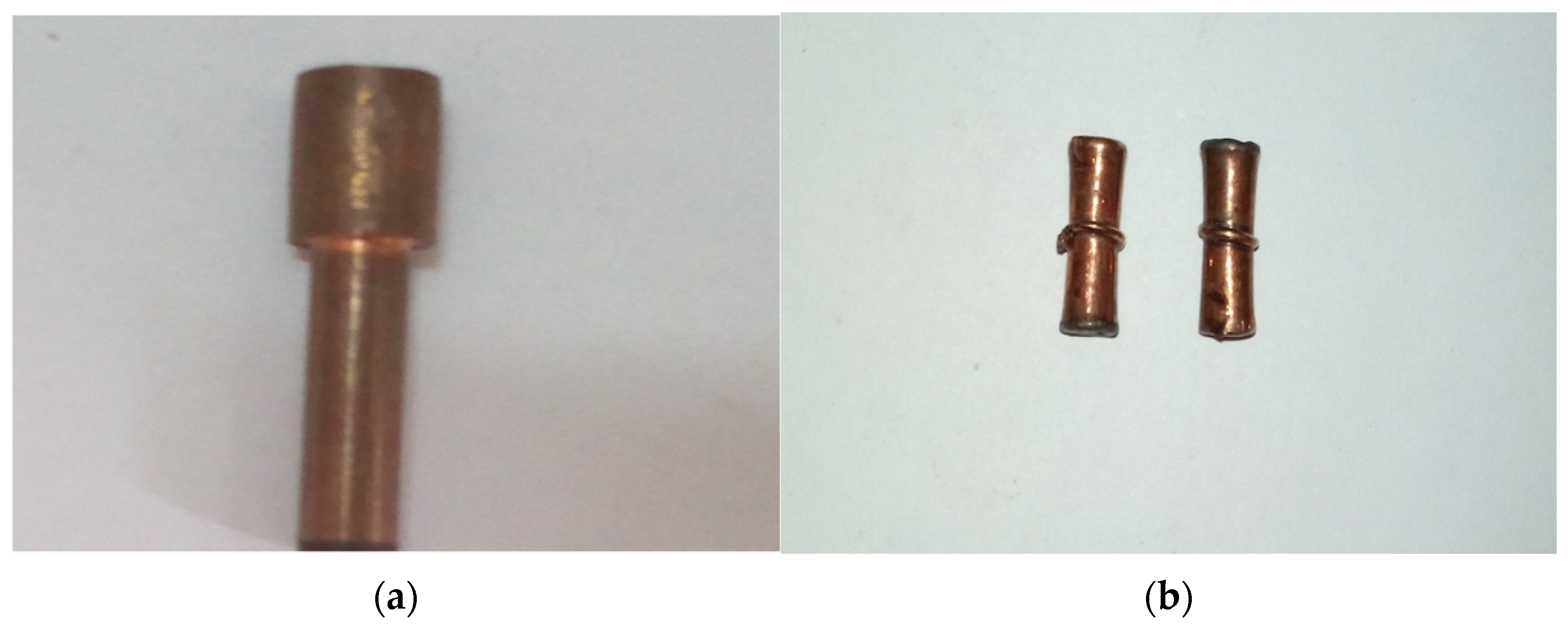
2.1. Electrode Production
2.2. Experimental Design, EDM, and Performance Measures
2.3. Analysis of Results, Comparisons, and Optimization
3. Results and Discussions
4. Optimization
5. Comparison of Machining Performances
6. Conclusions
- (1).
- ΔD achieved using novel electrodes is less when compared with ΔD obtained using SC electrodes.
- (2).
- ΔD produced by FDM-EM electrodes is comparable to ΔD achieved using novel electrodes at machine settings, which produces oversize cavities.
- (3).
- Undersize cavities produced using FDM-EM electrodes require further machining to achieve the desired dimension, which increases the machining cost.
- (4).
- Machining depth obtained with novel electrodes and FDM-EM electrodes is either less or more than the desired depth. However, the least variation in ΔH is observed when machining is performed using novel electrodes.
- (5).
- For both novel electrodes and FDM-EM electrodes, non-uniform deposition of copper at corners of primary metallized parts is responsible for the inexact depth produced during EDM.
- (6).
- The depth of cavities produced with SC electrodes is always more than the required depth, as it is a solid electrode, and there is no problem of copper deposition at corners like in novel electrodes and FDM-EM electrodes.
- (7).
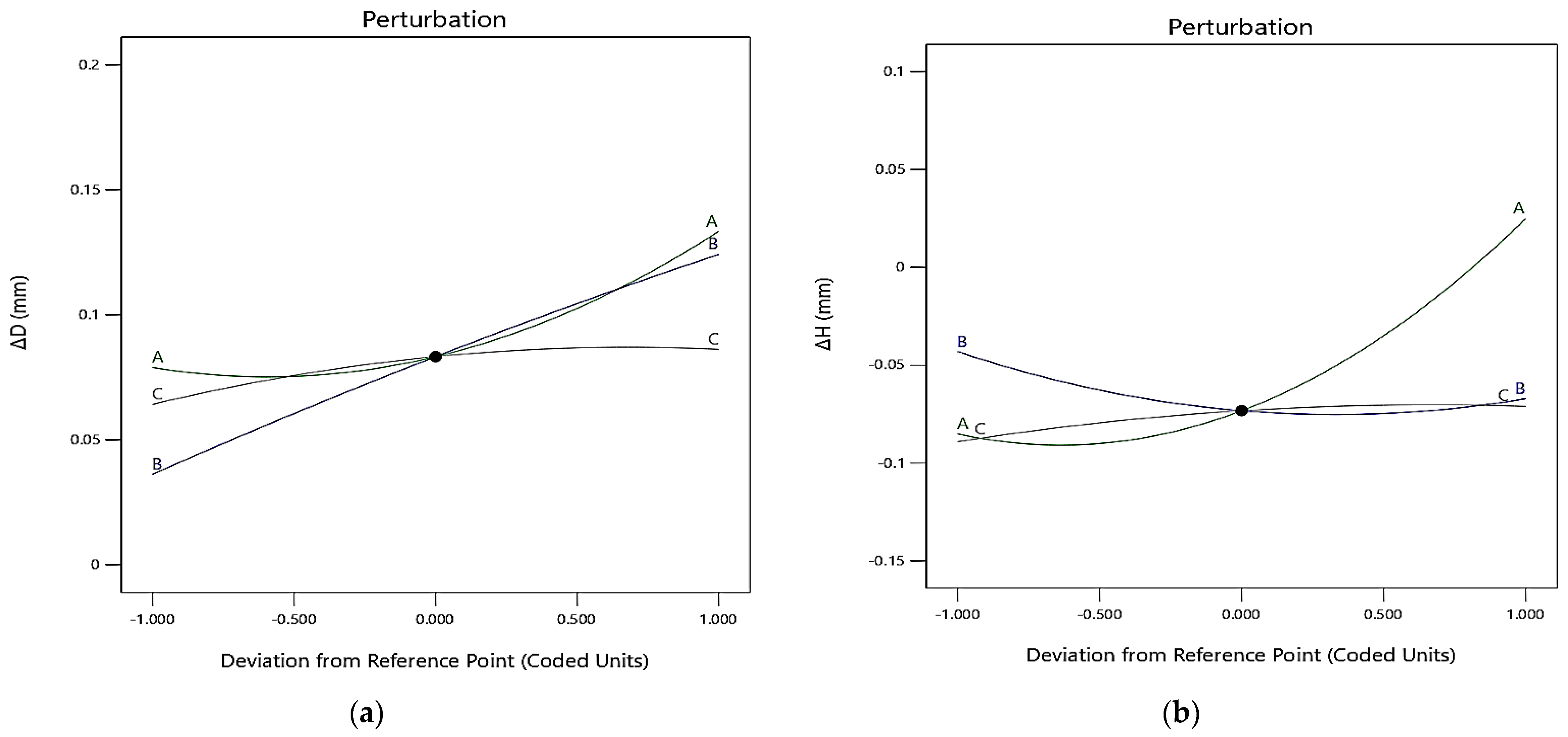
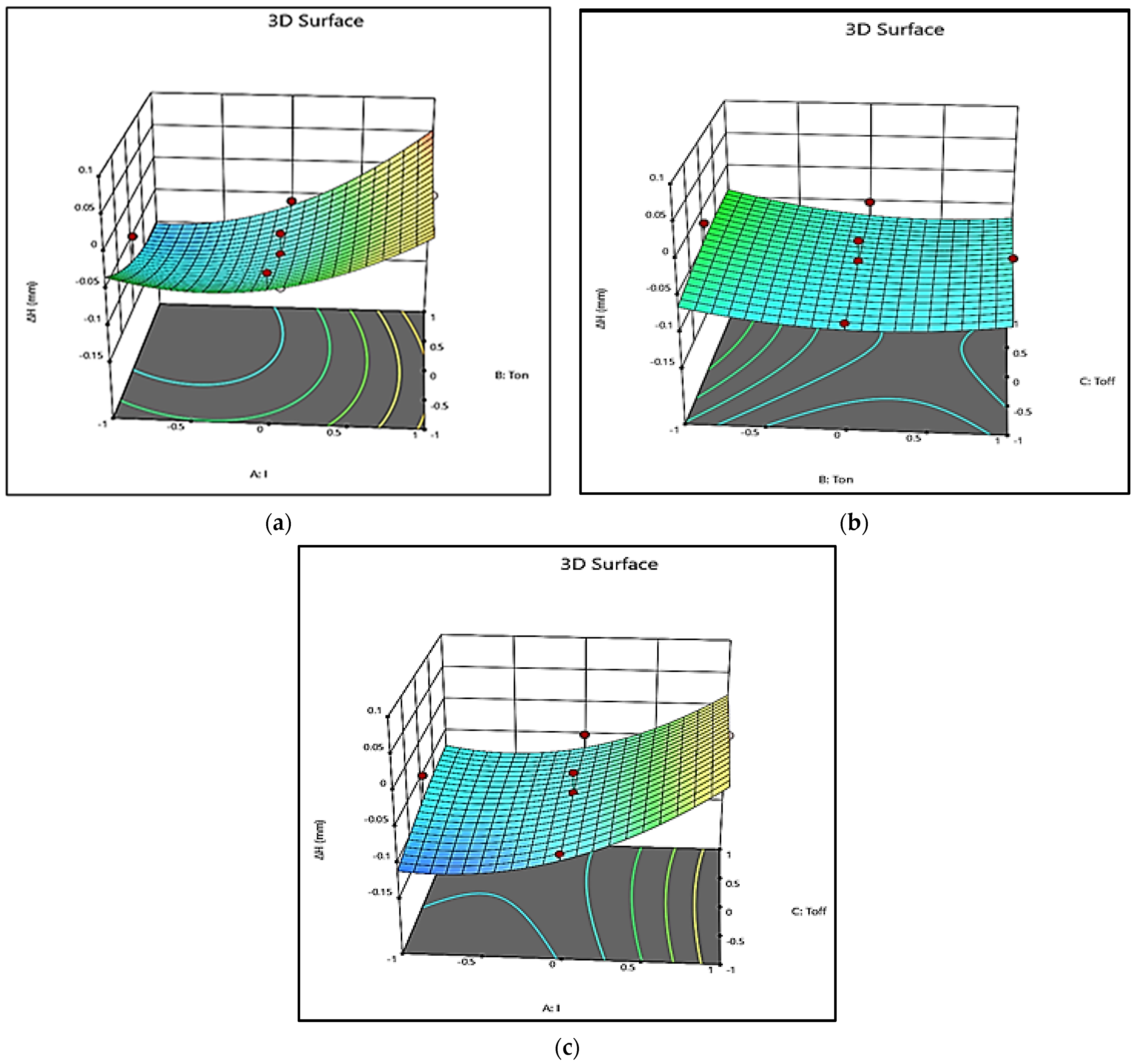
- ΔD is significantly affected by I and Ton, whereas I is the more dominating factor for ΔH.
- (8).
- From the result obtained, it is inferred that better dimensional accuracy is provided by novel electrodes when real-time machining was performed. It is also suggested that novel electrodes are recommended when finish machining is required using EDM, as the variations in ΔD and ΔH are minimum. In the real practice, the dimensional accuracy produced by the novel electrode is affected by inherent dimensional inaccuracy in FDM-fabricated parts as well as non-uniform deposition at the corners of the electrode due to continuous variation in current density.
- (9).
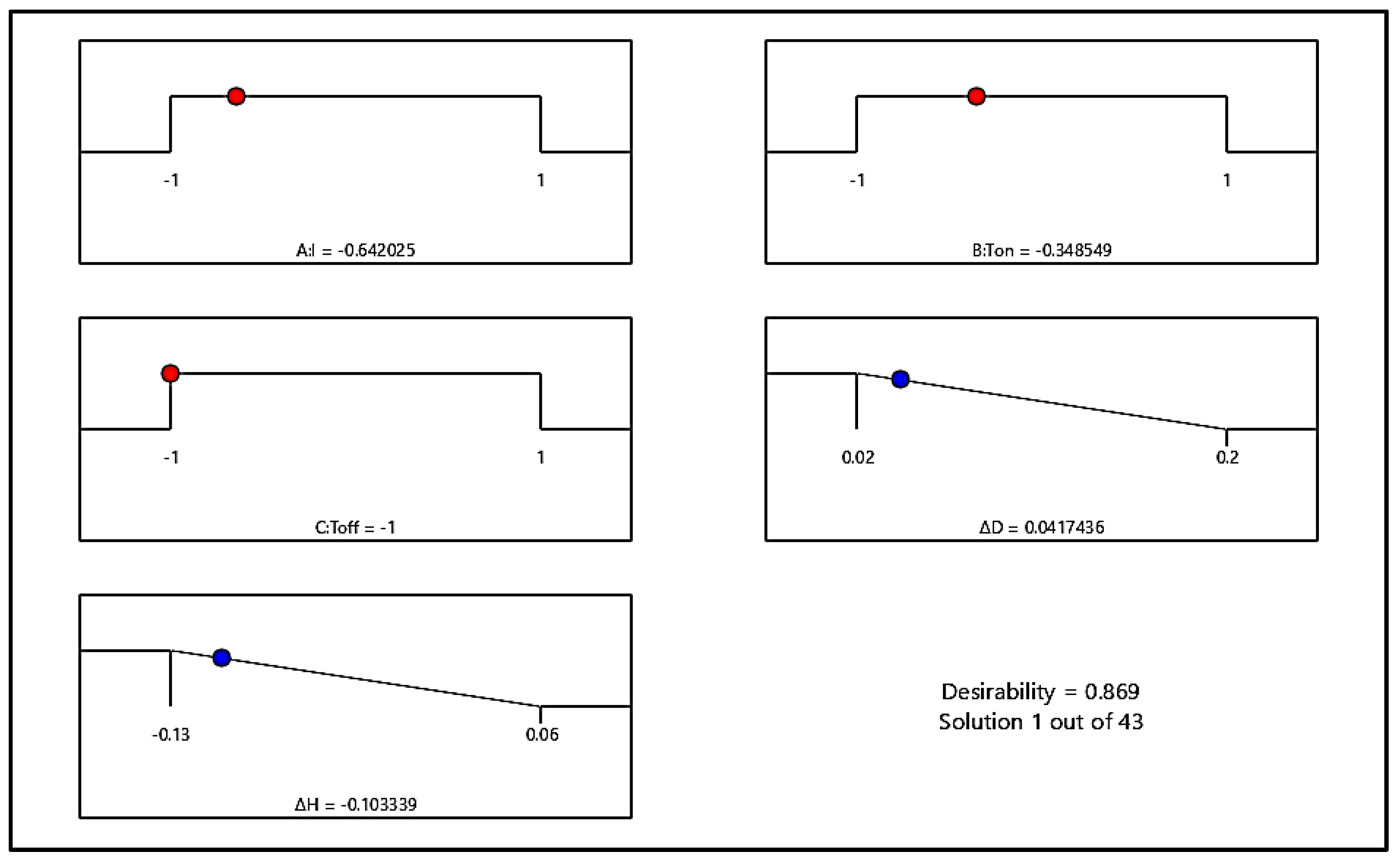
- Desirability-based optimization shows that for minimum ΔD and minimum ΔH, the optimal setting of the EDM parameters is I = 4.07 A, Ton = 148.68 µs, and Toff = 90 µs in coded form, and the values of ΔD and ΔH at the optimized setting are 0.0417436 and −0.103339 mm respectively.
Author Contributions
Funding
Institutional Review Board Statement
Informed Consent Statement
Data Availability Statement
Acknowledgments
Conflicts of Interest
References
- Baldin, V.; Baldin, C.R.B.; Machado, A.R.; Amorim, F.L. Machining of inconel 718 with a defined geometry tool or by electrical discharge machining. J. Braz. Soc. Mech. Sci. Eng. 2020, 42, 265. [Google Scholar] [CrossRef]
- Das, S.; Paul, S.; Doloi, B. Feasibility assessment of some alternative dielectric mediums for sustainable electrical discharge machining: A review work. J. Braz. Soc. Mech. Sci. Eng. 2020, 42, 148. [Google Scholar] [CrossRef]
- Chattopadhyay, K.D.; Verma, S.; Satsangi, P.S.; Sharma, P.C. Development of empirical model for different process parameters during rotary electrical discharge machining of copper–steel (EN-8) system. J. Mat. Proc. Tech. 2009, 209, 1454–1465. [Google Scholar] [CrossRef]
- Prabhu, S.; Uma, M.; Vinayagam, B.K. Electrical discharge machining parameters optimization using response surface methodology and fuzzy logic modelling. J. Braz. Soc. Mech. Sci. Eng. 2004, 36, 637–652. [Google Scholar] [CrossRef]
- Kumar, R.S.; Suresh, P. Experimental study on electrical discharge machining of Inconel using RSM and NSG A optimization technique. J. Braz. Soc. Mech. Sci. Eng. 2018, 41, 35. [Google Scholar] [CrossRef]
- Yang, R.T.; Tzeng, C.J.; Yang, Y.K.; Hsieh, M.H. Optimization of wire electrical discharge machining process parameters for cutting tungsten. Int. J. Adv. Manuf. Technol. 2012, 60, 135–147. [Google Scholar] [CrossRef]
- Altan, T.; Lilly, B.; Yena, Y.C.; Altan, T. Manufacturing of dies and molds. CIRP Ann. Manuf. Technol. 2001, 50, 404–422. [Google Scholar] [CrossRef]
- Ghodsiyeh, D.; Golshan, A.; Izman, S. Multi-objective process optimization of wire electrical discharge machining based on response surface methodology. J. Braz. Soc. Mech. Sci. Eng. 2014, 36, 301–313. [Google Scholar] [CrossRef]
- Sood, A.K.; Equbal, A. Feasibility of FDM-electroplating process for EDM electrode fabrication. Mater. Today Proc. 2020, 28, 1154–1157. [Google Scholar] [CrossRef]
- Equbal, A.; Equbal, M.I.; Sood, A.K. An investigation on the feasibility of fused deposition modelling process in EDM electrode manufacturing. CIRP J. Manuf. Sci. Technol. 2019, 26, 10–25. [Google Scholar] [CrossRef]
- Dhakshyani, R.; Nukman, Y.; Osman, A. Preliminary report: Rapid prototyping models for dysplastic hip surgery. Centr. Eur. J. Med. 2011, 6, 266–270. [Google Scholar] [CrossRef]
- Liu, Q.; Leu, M.C.; Schmitt, S.M. Rapid prototyping in dentistry: Technology and application. Int. J. Adv. Manuf. Technol. 2005, 29, 317–335. [Google Scholar] [CrossRef]
- Petzold, R.; Zeilhofer, H.F.; Kalender, W.A. Rapid prototyping technology in medicine-basics and applications. Comput. Med. Imag. Grap. 1999, 23, 277–284. [Google Scholar] [CrossRef]
- Wong, K.V.; Hernandez, A. A review of additive manufacturing. ISRN Mech. Eng. 2012, 2012, 208760. [Google Scholar] [CrossRef] [Green Version]
- Ding, D.; Shen, C.; Pan, Z. Towards an automated robotic arc-welding-based additive manufacturing system from CAD to finished part. Comput. Aided Des. 2016, 73, 66–75. [Google Scholar] [CrossRef] [Green Version]
- Equbal, A.; Dixit, N.K.; Sood, A.K. Electroless metallization of ABS plastic: A Comparative study. Int. J. Rapid Manuf. 2015, 5, 255–275. [Google Scholar] [CrossRef]
- Tang, X.; Cao, M.; Bi, C.; Yan, L.; Zhang, B. Research on a new surface activation process for electroless plating on ABS plastic. Mater. Lett. 2008, 62, 1089–1091. [Google Scholar] [CrossRef]
- Li, D.; Yan, C.L. Acidic electroless copper deposition on aluminium-seeded ABS plastics. Surf. Coat. Technol. 2009, 203, 3559–3568. [Google Scholar] [CrossRef]
- Equbal, A.; Sood, A.K. Investigations on metallization in FDM build ABS part using electroless deposition method. J. Manuf. Process. 2015, 19, 22–31. [Google Scholar] [CrossRef]
- Wang, C.C.; Lin, T.W.; Hu, S.S. Optimizing the rapid prototyping process by integrating the Taguchi method with the gray relational analysis. Rapid Prototyp. J. 2007, 13, 304–315. [Google Scholar] [CrossRef]
- Equbal, A.; Equbal, M.I.; Sood, A.K. PCA-based desirability method for dimensional improvement of part extruded by fused deposition modelling technology. Prog. Addit. Manuf. 2019, 4, 269–280. [Google Scholar] [CrossRef]
- Younis, A.M.; Abbas, M.D.; Gouda, M.F.; Allah, A.S.A. Effect of electrode material on electrical discharge machining of tool steel surface. Ain Shams Eng. J. 2015, 6, 977–986. [Google Scholar] [CrossRef] [Green Version]
- Kumar, R.; Sahani, O.P.; Vashista, M. Effect of EDM process parameters on tool wear. J. Basic Appl. Eng. Res. 2014, 1, 53–56. [Google Scholar]
- Singh, H.; Singh, A. Effect of pulse on/pulse off on machining of steel using cryogenic treated copper electrode. Int. J. Eng. Res. Dev. 2013, 5, 29–34. [Google Scholar]
- Costa, N.R.; Lourenço, J.; Pereira, Z.L. Desirability function approach: A review and performance evaluation in adverse conditions. Chemom. Intell. Lab. Syst. 2011, 107, 234–244. [Google Scholar] [CrossRef]


| Exp. No. | Factors (Coded) | ||
|---|---|---|---|
| I | Ton | Toff | |
| 1 | −1 | −1 | −1 |
| 2 | 1 | −1 | −1 |
| 3 | −1 | 1 | −1 |
| 4 | 1 | 1 | −1 |
| 5 | −1 | −1 | 1 |
| 6 | 1 | −1 | 1 |
| 7 | −1 | 1 | 1 |
| 8 | 1 | 1 | 1 |
| 9 | −1 | 0 | 0 |
| 10 | 1 | 0 | 0 |
| 11 | 0 | −1 | 0 |
| 12 | 0 | 1 | 0 |
| 13 | 0 | 0 | −1 |
| 14 | 0 | 0 | 1 |
| 15 | 0 | 0 | 0 |
| 16 | 0 | 0 | 0 |
| 17 | 0 | 0 | 0 |
| 18 | 0 | 0 | 0 |
| 19 | 0 | 0 | 0 |
| 20 | 0 | 0 | 0 |
| EDM Parameter | Symbol | Levels | Unit | ||
|---|---|---|---|---|---|
| 1 | 2 | 3 | |||
| Low Level (−1) | Center Level (0) | High Level (+1) | |||
| Current | I | 3 | 6 | 9 | A |
| Pulse on time | Ton | 90 | 180 | 270 | µs |
| Pulse on time | Toff | 90 | 120 | 150 | µs |
| Exp. No. | ΔD (mm) | ΔH (mm) |
|---|---|---|
| 1 | 0.020 | −0.07 |
| 2 | 0.060 | 0.02 |
| 3 | 0.070 | −0.13 |
| 4 | 0.180 | 0.06 |
| 5 | 0.040 | −0.03 |
| 6 | 0.080 | 0.03 |
| 7 | 0.130 | −0.10 |
| 8 | 0.200 | 0.04 |
| 9 | 0.090 | −0.05 |
| 10 | 0.102 | 0.02 |
| 11 | 0.040 | −0.02 |
| 12 | 0.100 | −0.06 |
| 13 | 0.070 | −0.08 |
| 14 | 0.060 | −0.05 |
| 15 | 0.090 | −0.04 |
| 16 | 0.060 | −0.09 |
| 17 | 0.110 | −0.10 |
| 18 | 0.070 | −0.07 |
| 19 | 0.120 | −0.08 |
| 20 | 0.090 | −0.12 |
| Source | DOF | ΔD | ΔH | ||||||
|---|---|---|---|---|---|---|---|---|---|
| SS | MS | F | p-Value | SS | MS | F | p-Value | ||
| I | 1 | 0.0074 | 0.0074 | 12.34 | 0.006 | 0.0302 | 0.0302 | 42.48 | 0.000 |
| Ton | 1 | 0.0194 | 0.0194 | 32.28 | 0.000 | 0.0014 | 0.0014 | 2.02 | 0.186 |
| Toff | 1 | 0.0012 | 0.0012 | 2.02 | 0.186 | 0.0008 | 0.0008 | 1.14 | 0.3113 |
| ITon | 1 | 0.0013 | 0.0013 | 2.08 | 0.179 | 0.0041 | 0.0041 | 5.69 | 0.0383 |
| IToff | 1 | 0.0002 | 0.0002 | 0.33 | 0.576 | 0.0008 | 0.0008 | 1.12 | 0.3141 |
| TonToff | 1 | 0.0002 | 0.0002 | 0.33 | 0.576 | 0.0002 | 0.0002 | 0.2809 | 0.6077 |
| II | 1 | 0.0014 | 0.0014 | 2.41 | 0.152 | 0.0051 | 0.0051 | 7.20 | 0.0230 |
| TonTon | 1 | 0.0000 | 0.0000 | 0.04 | 0.838 | 0.0009 | 0.0009 | 1.28 | 0.2849 |
| ToffToff | 1 | 0.0002 | 0.0002 | 0.30 | 0.596 | 0.0001 | 0.0001 | 0.1795 | 0.6807 |
| Residual error | 10 | 0.0060 | 0.0006 | -- | -- | 0.0071 | 0.0007 | -- | -- |
| LOF | 5 | 0.0034 | 0.0007 | 1.31 | 0.388 | 0.0034 | 0.0007 | 0.9074 | 0.5412 |
| Pure Error | 5 | 0.0026 | 0.0005 | -- | -- | 0.0037 | 0.0007 | -- | -- |
| Total | 19 | 0.0372 | -- | -- | -- | 0.0581 | -- | -- | -- |
| R2 = 0.839 | R2 = 0.877 | ||||||||
| Exp. No. | Factors (Coded) | ΔD (mm) | ΔH (mm) | ||||||
|---|---|---|---|---|---|---|---|---|---|
| I | Ton | Toff | Novel Electrode | SC Electrode [10] | FDM-EM Electrode [10] | Novel Electrode | SC Electrode [10] | FDM-EM Electrode [10] | |
| 1 | −1 | −1 | −1 | 0.020 | 0.21 | −0.06 | −0.07 | 0.07 | −0.12 |
| 2 | 1 | −1 | −1 | 0.060 | 0.13 | −0.02 | 0.02 | 0.05 | 0.04 |
| 3 | −1 | 1 | −1 | 0.070 | 0.20 | 0.05 | −0.13 | 0.04 | −0.20 |
| 4 | 1 | 1 | −1 | 0.180 | 0.26 | 0.29 | 0.06 | 0.11 | −0.04 |
| 5 | −1 | −1 | 1 | 0.040 | 0.22 | 0.03 | −0.03 | 0.03 | −0.01 |
| 6 | 1 | −1 | 1 | 0.080 | 0.20 | −0.10 | 0.03 | 0.04 | 0.02 |
| 7 | −1 | 1 | 1 | 0.130 | 0.15 | 0.18 | −0.10 | 0.03 | 0.09 |
| 8 | 1 | 1 | 1 | 0.200 | 0.32 | 0.31 | 0.04 | 0.11 | −0.02 |
| 9 | −1 | 0 | 0 | 0.090 | 0.22 | −0.15 | −0.05 | 0.04 | −0.09 |
| 10 | 1 | 0 | 0 | 0.102 | 0.24 | −0.02 | 0.02 | 0.11 | 0.03 |
| 11 | 0 | −1 | 0 | 0.040 | 0.25 | −0.11 | −0.02 | 0.04 | −0.01 |
| 12 | 0 | 1 | 0 | 0.100 | 0.30 | −0.04 | −0.06 | 0.07 | −0.16 |
| 13 | 0 | 0 | −1 | 0.070 | 0.27 | 0.11 | −0.08 | 0.09 | −0.02 |
| 14 | 0 | 0 | 1 | 0.060 | 0.29 | 0.05 | −0.05 | 0.09 | 0.00 |
| 15 | 0 | 0 | 0 | 0.090 | 0.31 | −0.15 | −0.04 | 0.07 | −0.02 |
| 16 | 0 | 0 | 0 | 0.060 | 0.30 | −0.10 | −0.09 | 0.11 | −0.14 |
| 17 | 0 | 0 | 0 | 0.110 | 0.32 | −0.06 | −0.10 | 0.15 | −0.16 |
| 18 | 0 | 0 | 0 | 0.070 | 0.30 | −0.08 | −0.07 | 0.11 | −0.14 |
| 19 | 0 | 0 | 0 | 0.120 | 0.32 | −0.08 | −0.08 | 0.13 | −0.14 |
| 20 | 0 | 0 | 0 | 0.090 | 0.31 | −0.09 | −0.12 | 0.10 | −0.13 |
| Root sum mean of square | 0.099 | 0.262 | 0.130 | 0.071 | 0087 | 0.101 | |||
Publisher’s Note: MDPI stays neutral with regard to jurisdictional claims in published maps and institutional affiliations. |
© 2021 by the authors. Licensee MDPI, Basel, Switzerland. This article is an open access article distributed under the terms and conditions of the Creative Commons Attribution (CC BY) license (https://creativecommons.org/licenses/by/4.0/).
Share and Cite
Equbal, A.; Equbal, A.; Khan, Z.A.; Badruddin, I.A.; Bashir, M.B.A.; Alrobei, H. Investigating the Dimensional Accuracy of the Cavity Produced by ABS P400 Polymer-Based Novel EDM Electrode. Polymers 2021, 13, 4109. https://0-doi-org.brum.beds.ac.uk/10.3390/polym13234109
Equbal A, Equbal A, Khan ZA, Badruddin IA, Bashir MBA, Alrobei H. Investigating the Dimensional Accuracy of the Cavity Produced by ABS P400 Polymer-Based Novel EDM Electrode. Polymers. 2021; 13(23):4109. https://0-doi-org.brum.beds.ac.uk/10.3390/polym13234109
Chicago/Turabian StyleEqubal, Azhar, Asif Equbal, Zahid A. Khan, Irfan Anjum Badruddin, Mohamed Bashir Ali Bashir, and Hussein Alrobei. 2021. "Investigating the Dimensional Accuracy of the Cavity Produced by ABS P400 Polymer-Based Novel EDM Electrode" Polymers 13, no. 23: 4109. https://0-doi-org.brum.beds.ac.uk/10.3390/polym13234109