Process Modeling, Optimization, and Heat Integration of Ethanol Reforming Process for Syngas Production with High H2/CO Ratio †


College of Chemistry & Chemical Engineering, Anhui University, Hefei 230601, China
*
Author to whom correspondence should be addressed.
†
Recommended by the China PSE2019 Conference.
Processes 2019, 7(12), 960; https://0-doi-org.brum.beds.ac.uk/10.3390/pr7120960
Submission received: 18 November 2019
/
Revised: 9 December 2019
/
Accepted: 13 December 2019
/
Published: 16 December 2019
(This article belongs to the Special Issue Process Optimization and Control)
Abstract
:The process modeling, parameter optimization, and heat integration of reforming ethanol to hydrogen is conducted in this paper. Modeling results show that the optimum reaction pressure for ethanol steam reforming is 1 bar. When the 7.4:1 is selected as a moderate water/ethanol ratio, the optimum reaction temperature is about 755 °C. As for heat integration, the composite curve and optimum heat-exchange network are given out by pinch technology, of which adding a heat exchanger can reduce 10,833 kW of heating duty and 10,833 kW of cooling duty and make the energy saving reach about 57.4%. Another two heat-integration plans are proposed for the ethanol steam-reforming process, to further decrease the high-level heat duty. Finally, similar heat integration was also carried out for the oxidative steam reforming, and the system is autothermal when the oxygen/ethanol is about 0.5:1 on the basis of above steam-reforming process, while the hydrogen molar purity is decreased from 69% to 66%.
1. Introduction
Hydrogen has always been considered the most attractive and promising energy carrier, since only water is generated during combustion or oxidation process [1]. At present, the main hydrogen production methods include water electrolysis, coal and biomass gasification, and reforming [2]. Among them, reforming of hydrocarbons, i.e., natural gas, is the most commonly used process for hydrogen production, owing to its mature technology and economic competitivity [3]. Natural gas is a kind of fossil fuel, and its usage will inevitably lead to a large amount of CO2 emissions caused by heating the steam reformer. The search for renewable feedstock for hydrogen production is urgently needed. Among different biomass-based compounds, ethanol is a promising hydrogen production feedstock for reforming technology because of its relatively high hydrogen content, availability, and storage safety [4].
The ethanol reforming processes for hydrogen production mainly include steam reforming, partial oxidation, and autothermal reforming [5]. The ethanol steam reforming is ethanol reaction with water stream, in the presence of catalysts. The steam reforming extracts more hydrogen atoms from the feedstocks and possesses an important advantage of relatively large hydrogen production [6]. However, steam reforming is a highly endothermic reaction, and high operation temperature is therefore necessary. The partial oxidation of ethanol is the incomplete oxidation of the ethanol into CO, CO2, and H2 by oxygen. The products are CO and H2 under the O2/ethanol molar ratio of 0.5, while the products are CO2 and H2 under the O2/ethanol molar ratio of 1.5 with releasing a lot of heat [7]. The autothermal reforming can realize self-heating by adjusting oxygen and steam-feed ratios, which includes both reactions of endothermic steam reforming and exothermic partial oxidation [8].
There are several research studies focused on modeling, simulation, and parameters analysis of ethanol-to-hydrogen processes. Garrido et al. [9] designed optimization-based controllers for an ethanol steam reformer in order to obtain the desired hydrogen flow under operational constraints. Rossetti et al. [10] calculated the equilibrium compositions of the ethanol steam reforming at different conditions and estimated their kinetic model parameters. Hedayati et al. [11] conducted dynamic simulation of ethanol steam reforming for hydrogen production in a catalytic membrane reactor. Serra et al. [12] developed a nonlinear dynamic model and conducted a static–dynamic analysis for the ethanol steam reforming with membrane separation process. Roychowdhury et al. [13] modeled the heat transfer of the ethanol steam-reforming process in a microchannel reactor, which found that the conversion rate can be reached as high as 100% when flue-gas flowing supplies the necessary heat. Afolabi et al. [14] established a microkinetic model of ethanol steam reforming over a nickel catalyst, which can correctly describe experimental trends. New concepts of self-sustained electrochemical promotion catalysts for partial oxidation of heavy hydrocarbons were also proposed in References [5,15]. Baruah et al. [16] developed a microkinetic model for the ethanol oxidative steam-reforming process, and it can be used in CFD software. However, these research studies did not take maximization hydrogen production of ethanol reforming as the objective function to obtain the optimal operating parameters. Moreover, the energy integration of the whole system was also not involved in these literatures. The purpose of this study is to establish two options of ethanol reforming (steam reforming with external fuel combustion heating and oxygen introduced into the reformer for self-heating), optimize the key operating parameters (temperature, pressure, and water/ethanol ratio) for the maximum hydrogen production at different H2/CO ratio, and then carry out the energy integration for the whole processes.
2. Modeling and Simulation
The main overall reactions of the ethanol steam reforming are shown in Equations (1) and (2) [7], which are highly endothermic reactions. CO and H2 are mainly produced with low water input, while CO2 and H2 are mainly produced by high water input. Despite the apparent simplicity of these two reactions, complex simultaneous reactions of ethanol decomposition (Equation (3)), methane steam reforming (Equations (4) and (6)), and water–gas shift (Equation (5)) can occur [14,17]. The heat needed for ethanol steam reforming can be obtained from fuel combustion out of the reaction tube. The other way is to add oxygen to ethanol for exothermic reactions of partial oxidation reforming, which are shown in Equations (7) to (9) [7]. However, the hydrogen production is largely reduced, especially for the option with an excess of oxygen input. The autothermal reforming combining the ethanol steam reforming and partial oxidation can realize self-heating and produce relatively large H2 production by adjusting oxygen and water inputs compared with the partial oxidation.
The steam reforming and autothermal reforming are both modeled by the Gibbs energy minimization model, which is a direct and useful method for calculating chemical equilibrium and phase equilibrium of complicated reactions. The property method of Peng–Rob is selected as thermodynamic method [10]. The objective function of Gibbs energy is shown in Equation (10), which is subjected to mass balance constraints in Equation (11) [18]. The composition of the product is determined according to the flows of ethanol and water, temperature, and pressure. The product gases are cooled and then separated from water by using a Flash model. The heating- or cooling-using utilities are modeled by the Heater model, while the heat exchanger matching hot stream and cold stream is modeled by the HeaterX model.
where C is the number of chemical species, P is the number of phases, S is the number of condensed species, njl is the moles of compound j in phase l, Gjl is the chemical potential of compound j in phase i, bk is the gram-atoms of element k, mjk is the number of atoms of element k in compound j, and E is the number of elements.
C2H5OH + H2O ←→ 4H2 + 2CO
C2H5OH + 3H2O ←→ 6H2 + 2CO2
C2H5OH ←→ C2H4O + H2 → CH4 + CO + H2
CH4 + H2O ←→ 3H2 + CO
CO + H2O ←→ H2 + CO2
CH4 + 2H2O ←→ 4H2 + CO2
2C2H5OH + O2 ←→ 6H2 + 4CO
2C2H5OH + 3O2 ←→ 6H2 + 4CO2
C2H5OH + 3O2 ←→ 3H2O + 2CO2
3. Results and Discussion
3.1. Optimization of Ethanol Reforming Process
To achieve the maximum hydrogen production of the ethanol reforming process, three operating variables of water/ethanol molar ratio, temperature, and pressure under the condition of ethanol input of 100 kmol/h for ethanol steam reforming were selected to meet the target of Equation (12) by solving the following optimization algorithm.
This is subject to the following:
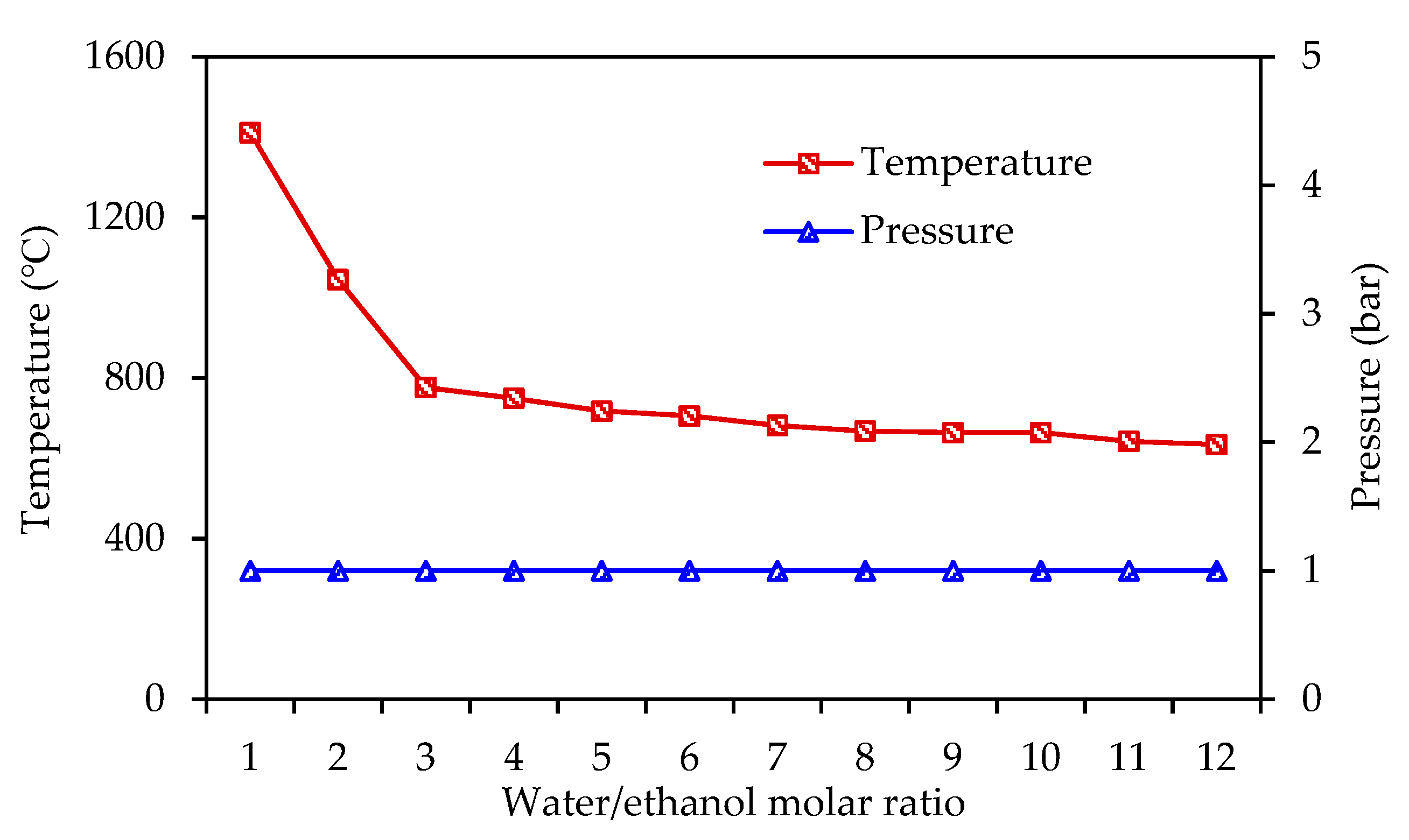
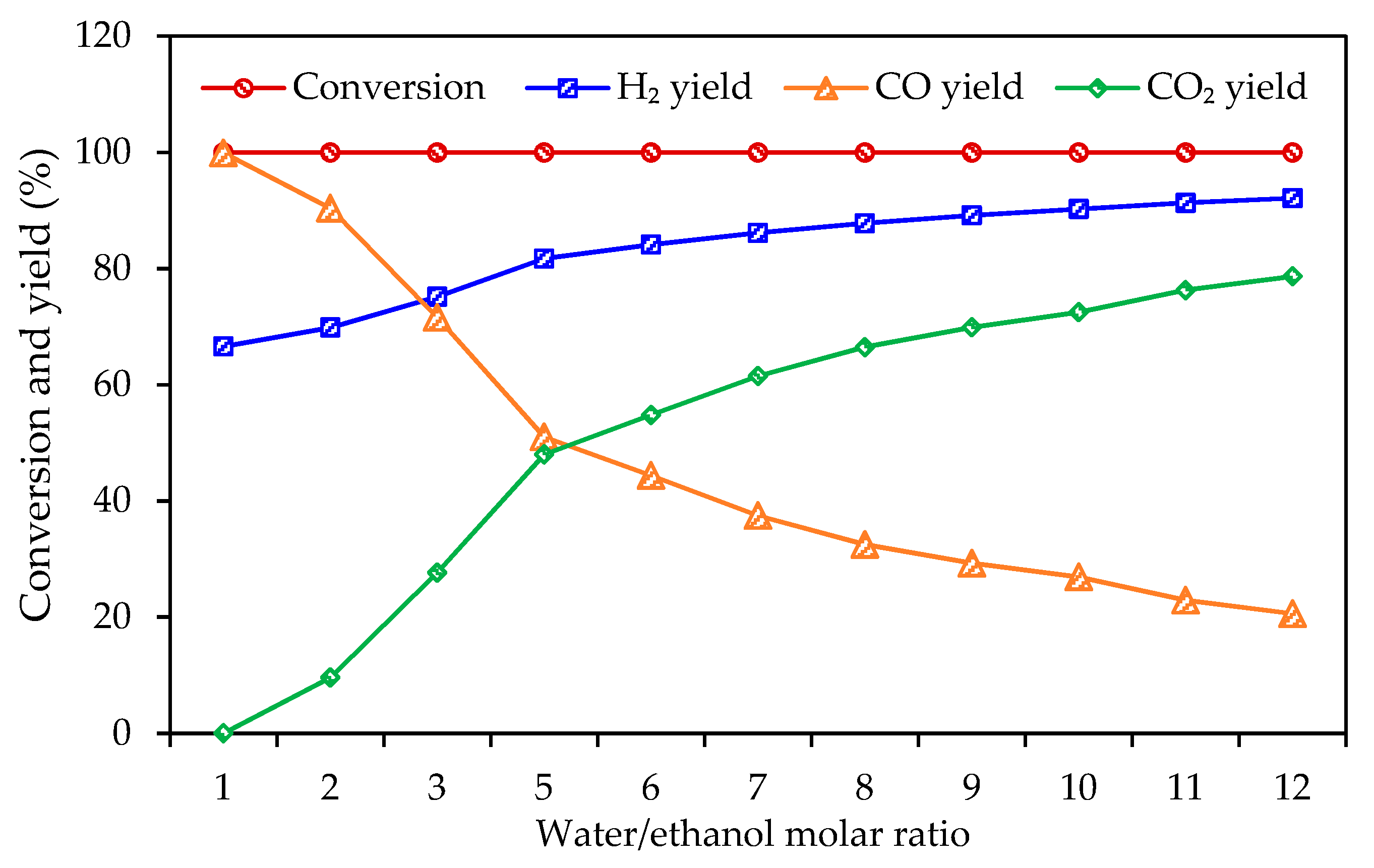
The effect of the water/ethanol molar ratio on the optimal reaction temperature and pressure for maximum hydrogen production is shown in Figure 1. Under the different water/ethanol ratio, the optimal reaction pressure for hydrogen production by ethanol steam reforming is 1 bar. According to equilibrium raw of a reversible reaction with gas reactant or product, when pressure is increased, the equilibrium always moves toward the direction of pressure reduction, i.e., in the negative reaction direction for the ethanol reforming due to its small gas coefficient in the negative reaction. Therefore, the yields of H2 and CO decrease significantly with increasing the reaction pressure. According to equilibrium law, the reaction moves toward the endothermic direction when increasing reaction temperature and the reaction moves toward the direction of decreasing reactant concentration when increasing feedstock input. Increasing the reaction temperature or water/ethanol ratio can increase H2 production. Therefore, the optimal reaction temperature is significantly decreased with the increase of the water input for the maximum H2 production. The effect of the water/ethanol feed ratio on the optimal ethanol conversion rate and product yields is shown in Figure 2. On the whole range, the optimal conversion rate of ethanol is close to 100%. With the increase of the water/ethanol ratio, the yields of H2 and CO2 increase significantly, while the yield of CO rapidly decreases, since increasing water input is beneficial to the water–gas shift reaction.
To achieve the maximum syngas production with a different H2/CO ratio of the ethanol reforming process, we selected three operating variables of H2O input, temperature, and pressure, with the ethanol input of 100 kmol/h for ethanol steam reforming, to meet the target of Equation (16), by solving the following optimization algorithm:
This is subject to the following:
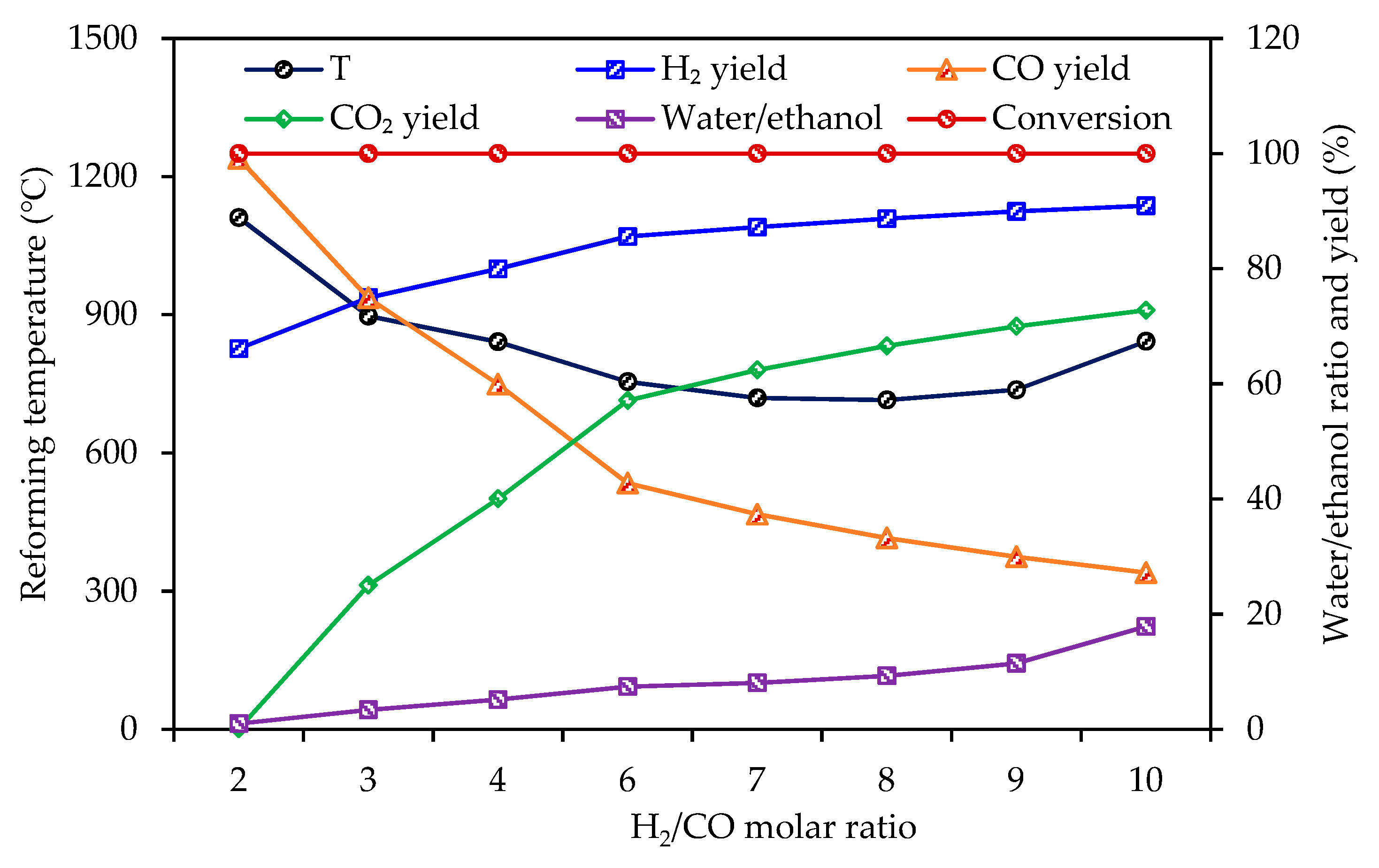
Under the constraint of different H2/CO molar ratio, the optimal reaction temperature, syngas yield, water/ethanol molar ratio, and conversion rate are shown in Figure 3. When the H2/CO is increased to 8, the reaction temperature is decreased to the minimum value of 714 °C. Thereafter, the reaction temperature gradually increases. On the whole range, the optimal conversion rate of ethanol is close to 100%. The yields of H2 and CO2 significantly increase, while the CO decreases quickly, and the water/ethanol ratio increases slowly, under the H2/CO below 6. If the H2/CO increases from 6 to 10, the yield of H2 increases a little, while CO decreases gradually, and the water/ethanol ratio is quickly increased to 17.8. Under the H2/CO of 6, the reaction temperature and water/ethanol ratio are 755 °C and 7.4, which are selected for the case study of heat integration.
3.2. Heat Integration of Ethanol Reforming Process
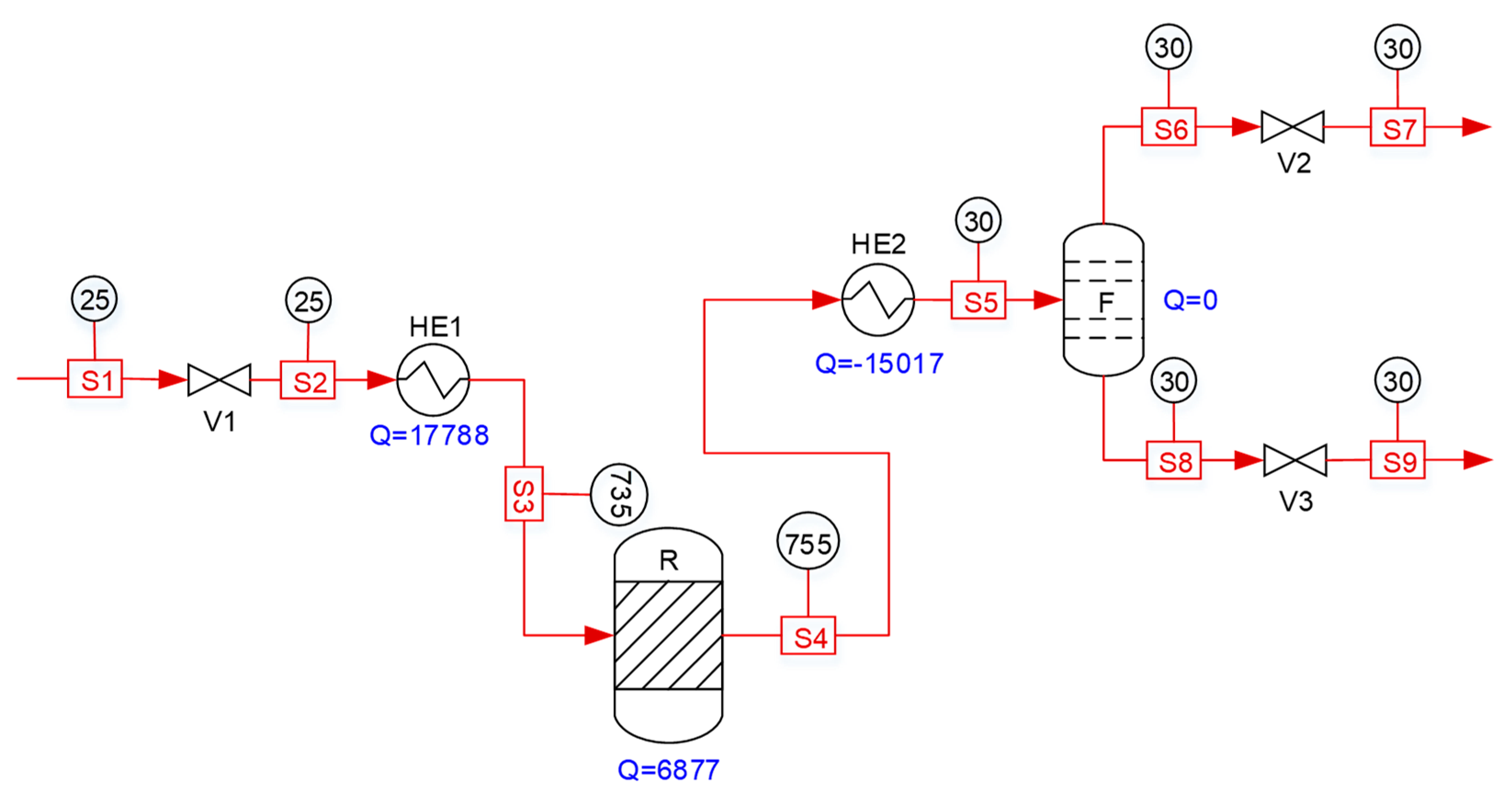
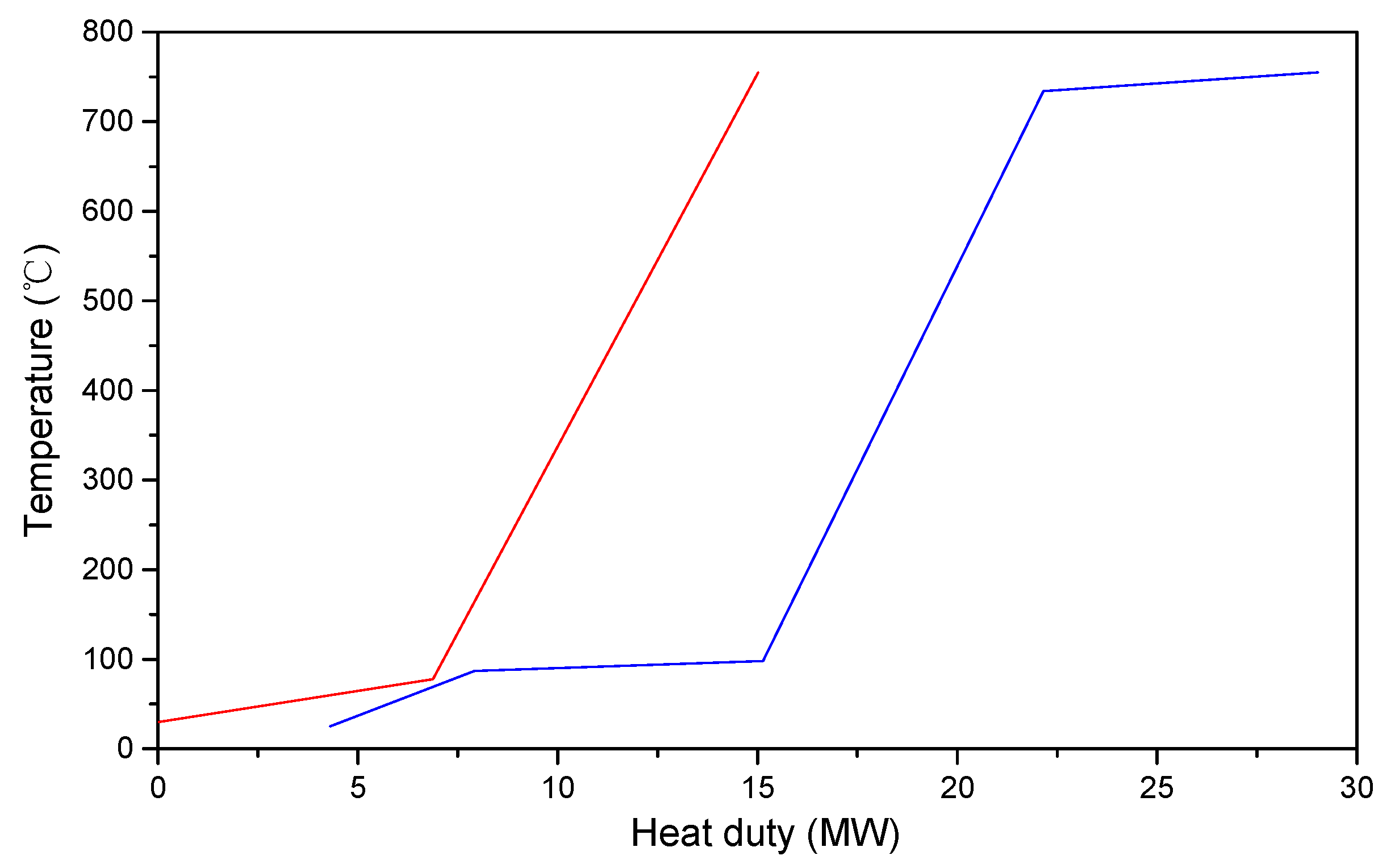
The ethanol steam reforming for hydrogen production process without heat integration is shown in Figure 4. The heating duty includes 17,788 kW of HE1 and 6877 kW of R, and the cooling duty is 15,017 kW, as also shown in Table 1. In order to use pinch technology, the first step is to draw a composite curve to determine the pinch point, as shown in Figure 5. The hot pinch temperature is 79.6 °C, and the cold pinch temperature is 69.6 °C.
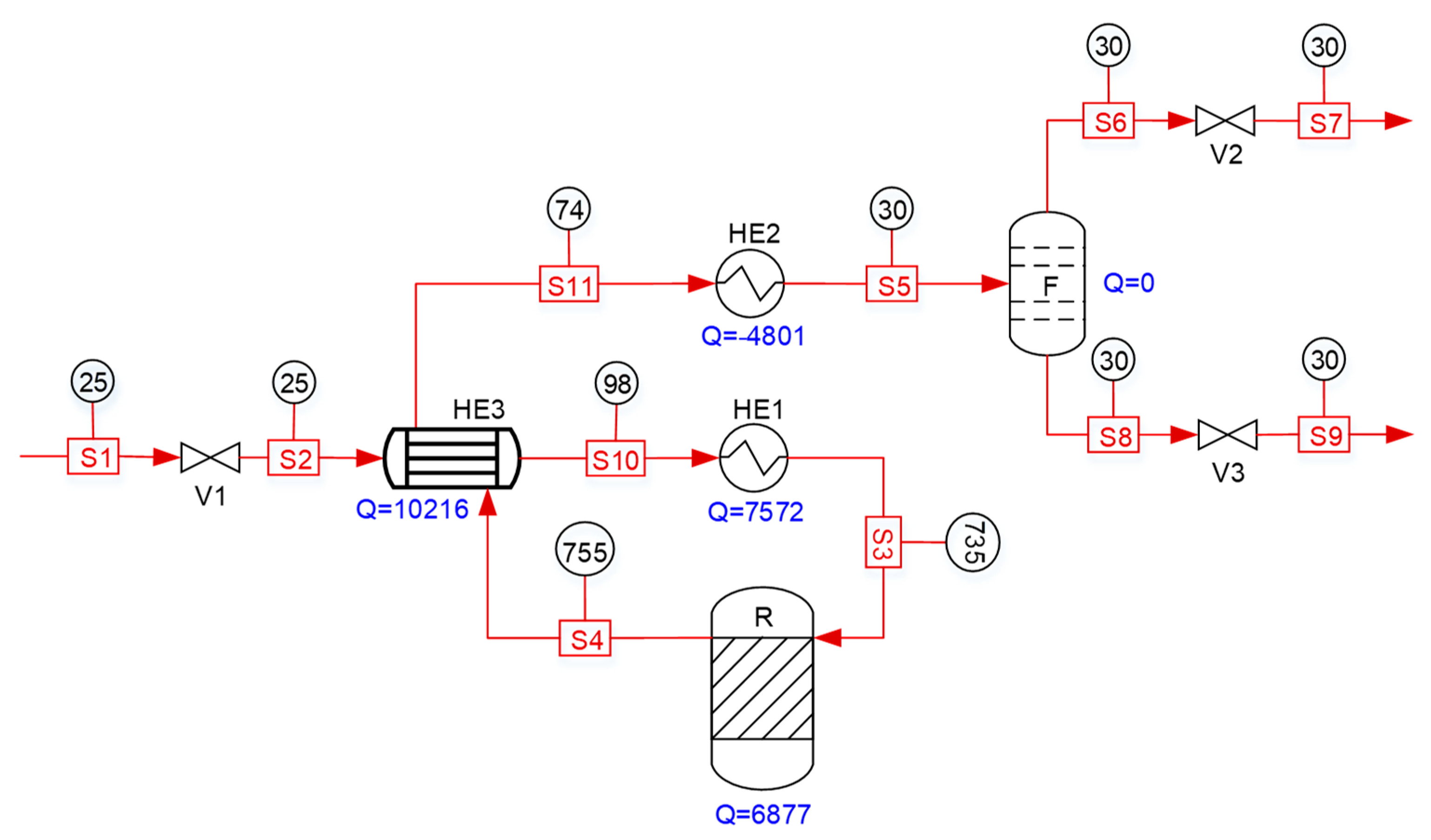
The design of the heat-exchange network and detailed modification processes according to pinch technology is shown in Figure 6. Matching heat exchange between the hot stream and cold stream, instead of separately using utilities to cool and heat, will greatly reduce utilities consumption. It can be seen that adding a heat exchanger can reduce 10,216 kW of heating duty and 10,216 kW of cooling duty and make the energy saving reach as high as 57.4%, as shown in Table 1. The heating duty only includes 7572 kW of HE1 and 6877 kW of R, and the cooling duty is decreased from 15,017 kW to 4801 kW. The shell-and-tube heat exchanger with countercurrent form is selected for the HE3, which has two shells and two tube passes. The overall heat-transfer coefficient is 253.4 W/m2·K under the 2502 tubes, with 6 m length arranged in a triangle. Under these conditions, the heat-transfer-area margin is about 23.3%.
In order to reduce the high-level heat demand, integration II is proposed in this paper and shown in Figure 7. The ethanol solution is first heated to a certain temperature, with low-pressure steam, and then exchanges heat with hot reformed gas in integration II (a) of Figure 7a. When the temperature is increased to 100 °C, the HE3 can heat ethanol solution to as high as 735 °C, and the high-level heat demand is reduced to 6877 kW, while the heat demand with low-level is increased to 10,833 kW and the cooling duty is also increased to 8062 kW, as shown in Table 1. The shell-and-tube heat exchanger is selected for the HE3, and the direction of the stream adopts the countercurrent form. The two shells and two tube passes are designed in this heat exchanger. The overall heat-transfer coefficient is 67.1 W/m2·K under the 5200 tubes with 9 m length arranged in a triangle. Under these conditions, the heat-transfer-area margin is about 18.5%.
On the basis of integration II (a), the hot reformed gas out of HE3 is further used to heat the ethanol solution from 25 to 87 °C in the HE4 for heat recovery, in which the reformed gas is cooled to 73 °C in integration II (b) of Figure 7(b). The overall heat-transfer coefficient of the HE4 is 242.3 W/m2·K under the 2874 tubes with 6 m arranged in a triangle. The heat-exchange margin is about 19.5% under the above conditions. Compared with integration I, the high-level heat demand is divided into 6877 kW high-level heat and 7285 kW low-level heat, as shown in Table 1. Compared with integration II (a), the low-level heat demand is reduced from 10,833 to 7285 kW, and cooling duty is also decreased from 8062 to 4514 kW.
As we can see, integration II (b) is the optimum heat-integration option among the above scenarios. Integration II (b) also needs high-level heat of 6877 kW from fuel combustion. The oxygen can directly be put into the ethanol reformer, to realize autothermal reforming. The effect of the oxygen/ethanol ratio on the heat duty and hydrogen molar fraction is shown in Figure 8. When the oxygen/ethanol ratio is zero, the process is the ethanol steam reforming; when the molar ratio of oxygen/ethanol is increased to about 0.5:1, the heat duty of ethanol reformer is about zero, and the H2 molar fraction is decreased from 69% to 66%.
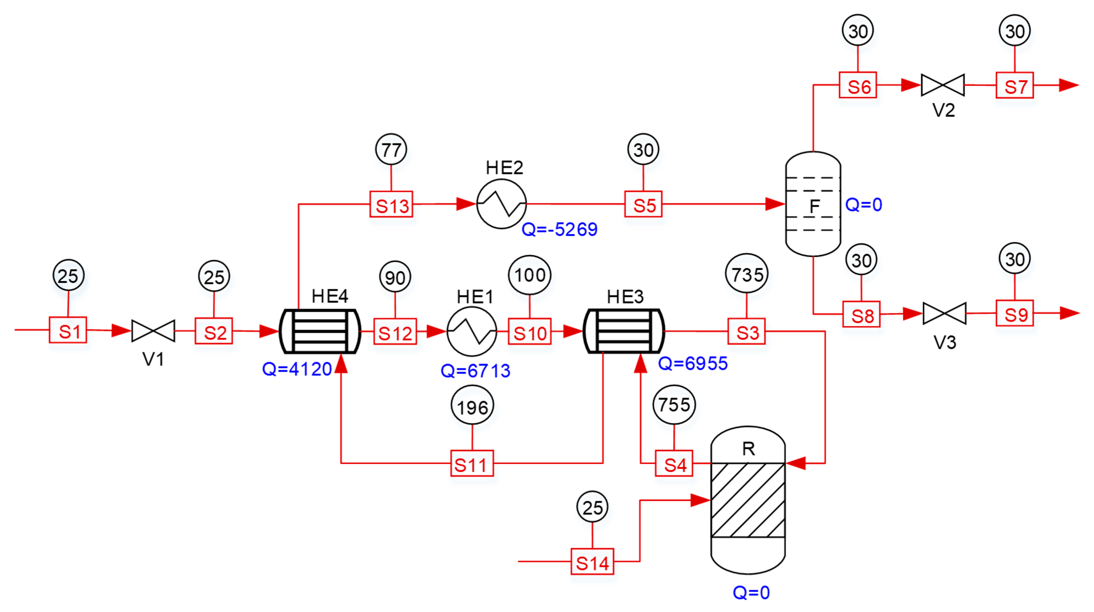
Heat integration III is the ethanol autothermal reforming process with oxygen/ethanol of 0.5:1 on the basis of integration II (b), whose heat-integration diagram is shown in Figure 9. The process needs only 6713 kW of low-pressure steam for heating and 5269 kW of cooling duty, as shown in Table 1. The shell-and-tube heat exchanger with the countercurrent form is selected for the HE3 and HE4. The overall heat-transfer coefficient is 95.1 W/m2·K under the 3282 tubes with 9 m length arranged in a triangle for the HE3, while the overall heat-transfer coefficient of the HE4 is 263.0 W/m2·K under the 2874 tubes, with 6 m length arranged in a triangle. Their heat-exchange margin is about 17.0% and 16.1% under the above conditions.
4. Conclusions
Among different biomass-based compounds, ethanol is a promising source for hydrogen production by reforming technology because of its relatively high hydrogen content, availability, and storage safety. Therefore, this work focuses on the study of process modeling, parameter optimization, and heat integration of the process of ethanol reforming to hydrogen-rich gas.
The ethanol reforming includes two heating models of steam reforming, with external fuel combustion heating and oxygen introduced into the reformer for self-heating. As for external heating option, the reforming optimum pressure of the ethanol steam reforming is 1 bar, while the reforming temperature gradually decreases as the water/ethanol molar ratio increases. When 7.4:1 is selected as a moderate water/ethanol ratio, the optimum reaction temperature is about 755 °C, and the H2/CO ratio is about 6:1. As for the inner heating option, the optimal oxygen/ethanol molar ratio is about 0.5:1 on the basis of the above optimization parameters of ethanol steam reforming.
After parameters’ optimization, the heat integration is carried out by pinch technology, to determine pinch temperature of 79.6 °C for the hot side and 69.6 °C for the cold side and the initial heat-exchange network, in which adding a heat exchanger can make the energy saving reach about 57.4%. Another two heat-integration plans are proposed for the ethanol steam-reforming process, to further replace 7572 kW of the high-level heating duty by 10,833 kW and 7285 kW low-level heating duty, respectively. On the basis of the second heat-integration plan, the steam-oxygen reforming with oxygen/ethanol of 0.5:1 can eliminate the 6877 kW heating duty of the steam reformer and only needs 6713 kW of low-level heating duty and 5269 kW of cooling duty.
Author Contributions
Conceptualization, methodology, and validation, D.X.; investigation, P.L.; writing-original draft preparation, D.X.; writing-review and editing, D.X and P.L.; supervision, D.X. and X.Y.; project administration, D.X.; funding acquisition, D.X.
Funding
The authors are grateful for financial support from the Anhui Provincial Natural Science Foundation (No: 1808085QB46) and the National Natural Science Foundation of China (No: 21706001).
Conflicts of Interest
The authors declare no conflicts of interest.
References
- Sun, S.H.; Yan, W.; Sun, P.Q.; Chen, J.W. Thermodynamic analysis of ethanol reforming for hydrogen production. Energy 2012, 44, 911–924. [Google Scholar] [CrossRef]
- Zhang, M.; Zhang, S.H.; Zhang, Z. Simulation research of hydrogen production from ethanol steam reforming. Nat. Gas Chem. Ind. 2014, 39, 70–72. [Google Scholar]
- Liu, T.; Hu, S.X.; Yu, Z.L.; Huang, J.J.; Li, J.Z.; Wang, Z.Q.; Fang, Y.T. Research of coal-direct chemical looping hydrogen generation with iron-based carrier modified by potassium. Int. J. Hydrog. Energy 2017, 42, 11038–11046. [Google Scholar] [CrossRef]
- Ni, M.; Leung, D.Y.C.; Leung, M.K.H. A review on reforming bio-ethanol for hydrogen production. Int. J. Hydrog. Energy 2007, 32, 3238–3247. [Google Scholar] [CrossRef]
- Wang, Z.D.; Huang, H.; Liu, H.T.; Zhou, X.Y. Self-sustained electrochemical promotion catalysts for partial oxidation reforming of heavy hydrocarbons. Int. J. Hydrog. Energy 2012, 37, 17928–17935. [Google Scholar] [CrossRef]
- Pirez, C.; Fang, W.H.; Capron, M.; Paul, S.; Jobic, H.; Dumeignil, F.; Duhamel, L.J. Steam reforming, partial oxidation and oxidative steam reforming for hydrogen production from ethanol over cerium nickel based oxyhydride catalyst. Appl. Catal. A Gen. 2016, 518, 78–86. [Google Scholar] [CrossRef]
- Rabenstein, G.; Hacker, V. Hydrogen for fuel cells from ethanol by steam-reforming, partial-oxidation and combined auto-thermal reforming: a thermodynamic analysis. J. Power Sour. 2008, 185, 1293–1304. [Google Scholar] [CrossRef]
- Huang, L.H.; Chen, R.R.; Chu, D.; Hsu, A.T. Hydrogen production through auto-thermal reforming of bio-ethanol oven Co-based catalysts: effect of iron in Co/Al2O3 catalysts. Int. J. Hydrog. Energy 2010, 35, 1138–1146. [Google Scholar] [CrossRef]
- Garrido, D.R.; Martinez, C.O.; Prat, M.S. Design of optimization-based controllers applied to an ethanol steam reformer for hydrogen production. Int. J. Hydrog. Energy 2012, 37, 11141–11156. [Google Scholar] [CrossRef] [Green Version]
- Rossetti, I.; Compagnoni, M.; Torli, M. Process simulation and optimisation of H2 production from ethanol steam reforming and its use in fuel cells. 1. thermodynamic and kinetic analysis. Chem. Eng. J. 2015, 281, 1024–1035. [Google Scholar] [CrossRef]
- Hedayati, A.; Corre, O.L.; Lacarriere, B.; Llorca, J. Dynamic simulation of pure hydrogen production via ethanol steam reforming in a catalytic membrane reactor. Energy 2016, 117, 316–324. [Google Scholar] [CrossRef]
- Serra, M.; Martinez, C.O.; Li, M.; Llorca, J. Model predictive control for ethanol steam reformers with membrane separation. Int. J. Hydrog. Energy 2017, 42, 1949–1961. [Google Scholar] [CrossRef] [Green Version]
- Roychowdhury, S.; Sundararajan, T.; Das, S.K. Conjugate heat transfer studies on steam reforming of ethanol in micro-channel systems. Int. J. Heat Mass Transf. 2019, 139, 660–774. [Google Scholar] [CrossRef]
- Afolabi, A.T.F.; Li, C.Z.; Kechagiopoulos, P.N. Microkinetic modelling and reaction pathway analysis of the steam reforming of ethanol over Ni/SiO2. Int. J. Hydrog. Energy 2019, 44, 22816–22830. [Google Scholar] [CrossRef]
- Huang, H.; Wang, Z.; Zhou, X.; Liu, H.; Wei, Y. Development and study of self-sustained electrochemical promotion catalysts for hydrocarbon reforming. ECS Trans. 2013, 58, 243–254. [Google Scholar] [CrossRef]
- Baruah, R.; Dixit, M.; Parejiya, A.; Basarkar, P.; Bhargav, A.; Sharma, S. Oxidative steam reforming of ethanol on rhodium catalyst-I: spatially resolved steady-state experiments and microkinetic modeling. Int. J. Hydrog. Energy 2017, 42, 10184–10198. [Google Scholar] [CrossRef]
- Sahoo, D.R.; Vajpai, S.; Patel, S.; Pant, K.K. Kinetic modeling of steam reforming of ethanol for the production of hydrogen over Co/Al2O3 catalyst. Chem. Eng. J. 2007, 125, 139–147. [Google Scholar] [CrossRef]
- White, C.W.; Seider, W.D. Computation of phase and chemical equilibrium part IV: approach to chemical equilibrium. AIChE J. 1981, 27, 466–471. [Google Scholar] [CrossRef]
Figure 1.
The effect of the water/ethanol molar ratio on the optimal reaction temperature and pressure.
Figure 1.
The effect of the water/ethanol molar ratio on the optimal reaction temperature and pressure.

Figure 2.
The effect of the water/ethanol molar ratio on the optimal ethanol conversion and product yield.
Figure 2.
The effect of the water/ethanol molar ratio on the optimal ethanol conversion and product yield.

Figure 3.
The optimal reaction temperature, product yield, and water/ethanol molar ratio under the constraint of different H2/CO molar ratios.
Figure 3.
The optimal reaction temperature, product yield, and water/ethanol molar ratio under the constraint of different H2/CO molar ratios.

Figure 4.
The ethanol steam reforming for hydrogen production process without heat integration.

Figure 5.
Composite curve of the ethanol steam reforming for hydrogen production process.

Figure 6.
Heat integration-I of the ethanol steam reforming for hydrogen production process.

Figure 7.
Heat integration-II of the ethanol reforming for hydrogen production.

Figure 8.
The effect of the oxygen/ethanol molar ratio on the heat duty of the ethanol reformer and hydrogen molar fraction.
Figure 8.
The effect of the oxygen/ethanol molar ratio on the heat duty of the ethanol reformer and hydrogen molar fraction.

Figure 9.
Heat integration-III of the ethanol autothermal reforming for hydrogen production.


Table 1.
The heat duty distribution of the studied cases.
| Heat Duty | Base Case | Integration I | Integration II (a) | Integration II (b) | Integration III |
|---|---|---|---|---|---|
| HE1 (kW) | 17,788 | 7572 | 10,833 | 7285 | 6713 |
| HE2 (kW) | −15,017 | −4801 | −8062 | −4514 | −5269 |
| HE3 (kW) | 0 | 10,216 | 6955 | 6955 | 6955 |
| HE4 (kW) | 0 | 0 | 0 | 3548 | 4120 |
| R (kW) | 6877 | 6877 | 6877 | 6877 | 0 |
© 2019 by the authors. Licensee MDPI, Basel, Switzerland. This article is an open access article distributed under the terms and conditions of the Creative Commons Attribution (CC BY) license (http://creativecommons.org/licenses/by/4.0/).
Share and Cite
MDPI and ACS Style
Xiang, D.; Li, P.; Yuan, X. Process Modeling, Optimization, and Heat Integration of Ethanol Reforming Process for Syngas Production with High H2/CO Ratio. Processes 2019, 7, 960. https://0-doi-org.brum.beds.ac.uk/10.3390/pr7120960
AMA Style
Xiang D, Li P, Yuan X. Process Modeling, Optimization, and Heat Integration of Ethanol Reforming Process for Syngas Production with High H2/CO Ratio. Processes. 2019; 7(12):960. https://0-doi-org.brum.beds.ac.uk/10.3390/pr7120960
Chicago/Turabian StyleXiang, Dong, Peng Li, and Xiaoyou Yuan. 2019. "Process Modeling, Optimization, and Heat Integration of Ethanol Reforming Process for Syngas Production with High H2/CO Ratio" Processes 7, no. 12: 960. https://0-doi-org.brum.beds.ac.uk/10.3390/pr7120960
Note that from the first issue of 2016, this journal uses article numbers instead of page numbers. See further details here.