Prediction of Cutting Material Durability by T = f(vc) Dependence for Turning Processes


Department of Automobile and Manufacturing Technologies, Institute of Advanced Technologies, Faculty of Manufacturing Technologies with a seat in Presov, Technical University of Kosice, Bayerova 1, 080 01 Presov, Slovakia
*
Author to whom correspondence should be addressed.
Processes 2020, 8(7), 789; https://0-doi-org.brum.beds.ac.uk/10.3390/pr8070789
Submission received: 1 June 2020
/
Revised: 29 June 2020
/
Accepted: 2 July 2020
/
Published: 6 July 2020
(This article belongs to the Special Issue Redesign Processes in the Age of the Fourth Industrial Revolution)
Abstract
:This article is focused on the prediction of cutting material durability by Taylor’s model. To create predictive models of the durability of cutting materials in the turning process, tools made of high-speed steel, sintered carbide without coating and with Titanium nitride (TiN) coating, cutting ceramics without coating and with TiN coating were applied. The experimental part was performed on reference material C45 using conventional lathe—type of machine SU50A and computer numerical control machine—CNC lathe Leadwell T-5 in accordance with International Organization for Standardization—ISO 3685. Implementation of the least-squares method and processing of regression analysis made predictions of cutting tool behaviour in the turning process. Using the method of regression analysis, a correlation index of 93.5% was obtained, indicating the functional dependence of the predicted relationship.
1. Introduction
The production process is influenced by a large number of factors, but it is possible to predict partial parts of the production process, such as the durability of the cutting tool [1], the geometrical accuracy of the machined surface [2], and so on [3,4,5]. The best prediction is based on the analytical expression, i.e., the formula, which is most likely to apply to specific situations. One of such formulas is also the F.W. Taylor formula, which is contained in STN ISO 3685, and which is intended to predict the durability of the cutting tool in the machining process:
- cT—constant (derived from measured data or computed using the least squared method), (-)
- vc—cutting speed (m/min),
- m—index (dependence of cutting speed on tool-life).
and the extended form of formula:
- vcT—cutting speed (constant tool-life)
- ap—depth of cut (mm)
- f—feed (mm)
- xv—index (expression of depth of cut effect)
- yv—index (expression of feed rate).
Several authors have addressed the issue of durability of cutting materials in their research area. In 2014, a team of authors presented at the ASME Congress, Congress of The American Society of Mechanical Engineers research aimed at studying the life of uncoated inserts utilized in the dry turning. Tool life was evaluated using flank wear (VB) measurement in accordance with ISO 3685 standard. The results showed that tool life decreases with the speed following a potential model [6]. The ISO 3685 standard was also applied to evaluate the machinability of turning steel marked as SAE 1020. Diaz et al. [7] introduced a new methodology for evaluating the machinability of this material (SAE 1020), which is produced in Venezuela. The results of the work were determined by the Taylor model and also the surface quality and chip type. The aim of the research of authors Dhabale et al. [8] was to investigate the effects of process parameters on the performance measure, namely material removal rate and surface roughness using the Taguchi method (a method used to find the minimum number of experiments to be performed within the permissible limit of factors and levels) and analysis of variance. The results revealed that spindle speed, feed rate and depth of cut are the most significant parameters that influence material removal rate and the most significant parameters which influence surface roughness are feed rate and depth of cut [8]. In the turning process, optimization of process parameters was also described by the Taguchi method by Chethan et al. [9].
Dubovska et al. [10] presented austenitic durability research with stainless steel coated carbide insert. The paper described the performance optimization of the turning process of the austenitic stainless steel AISI 304 used for special applications with their dominant functional areas. Also important was the research by Iliescu [11], who described the durability of the cutting tool through regression models. The specificity of the research consisted of examining a thermally sprayed coating tool. The author Iliescu [12] also described the durability of cutting tools with metallized coatings in turn by using regression models in his next research. A new proposal for tool-life analysis was also presented in the contribution which included generalizations of Taylor’s model in accordance with ISO 3685 standard [13]. In 2015, a paper was published describing the study of hard material machining (Inconel 718 and Inconel 625) in the milling process [14]. Using a standard cost optimization model, process parameters were optimized considering the trade-off between material removal rate and tool life. The coefficients estimated for the extended Taylor’s tool life model were also validated. In the next paper, author Nicolich [1] describes the comparison between two different experimental methods for predicting the cutting-edge tool life in turning: Standard ISO 3685 and the proposed one that is mentioned here, that make free the variation of cutting parameters, in particular the cutting speed. The issue of experimental determination of the durability of the cutting tool during machining was also discussed by Petru et al. [15] who experimentally determined the wear of three kinds of cutting tools during machining of the alloy. Based on the results obtained, it was concluded that it was advantageous to use positive geometry with the angle of the main cutting edge of 45° for machining of Titanium alloys. Additionally, round (large radius) inserts are suitable for machining of Titanium alloys, where the angle of the main cutting edge can be changed depending on the depth of machined material. In 2017, research was carried out describing tool-life modelling based on cutting parameters and hardness in the turning process. In this paper, the methodology for the development of a life prediction model for tool during the turning of hardened steel at different levels of hardness was presented [16]. The issue of cutting tool wear monitoring was discussed by Sadilek et al. [17], Čep et al. [18], Majernikova et al. [19] and Bakša [20]. Authors Chaus and Rudnitskii [21,22] described the results of research focused on the influence of cutting conditions of cast-metal cutting tools on their wear and durability. In 2011, authors Gill et al. [23,24] presented studies focused on flank wear and machining performance. The comprehensive studies of machinability of alloy steels dealing with the durability of cutting tools were described by Caballero et al. [25], Hao et al. [26], Jaworski et al. [27] and so on [28,29,30]. In the turning process, the tool life issue was also described by Che-Haron [31]. In this research, the tool wear and surface integrity effects when machining titanium alloy Ti-6Al-2Sn-4Zr-6Mo under a dry cutting condition was investigated. The issue of tool life in dry diamond turning of titanium alloys is described in [32] and [33], too. A similar issue (machinability and tool life) was discussed in the paper by Kamruzzaman et al. [34]. In this research, durability after the turning process of nickel-based superalloy using coated carbide inserts was described. The tool life and tool wear in taper turning of a nickel-based superalloy were discussed by Antonialli et al. [35]. Results showed that taper turning was not successful in terms of tool life, although the furrowing mechanism of the tool coating caused by the hard burr formed, that led to notch wear, was avoided. Prediction of tool life after the turning process was discussed by Priarone et al. [36] and Da Silva et al. [37] with the use of various forms of cooling and use of a minimum quantity of lubricant principle in [38,39,40].
In the aforementioned state of the art, previous studies have been presented, in which the possibilities for creating relations (formulas) for wear of cutting materials have been described. Individual proposals have been described with designs made using one type of machine or tool. In the present study, the proposal of mathematical methods for the durability of cutting materials is described in the scope of several cutting materials, followed by machining after conventional turning and CNC machining.
2. Materials and Methods
Experiments have been implemented in accordance with ISO 3685 standard, which is designated for durability tests in machining (turning) of workpieces made of steels, cast iron and ceramics. According to the standard, the reference material and the conditions defined by this standard were used in the experiments. The standard specifies the durability tests of single cutting edge tools for the following factors: workpieces, tools, cutting fluid, cutting conditions, accessories, assessment of tool life, test procedures, recording, evaluation, and reporting of results. The following section describes the individual parts of the machine-tool-work piece system.
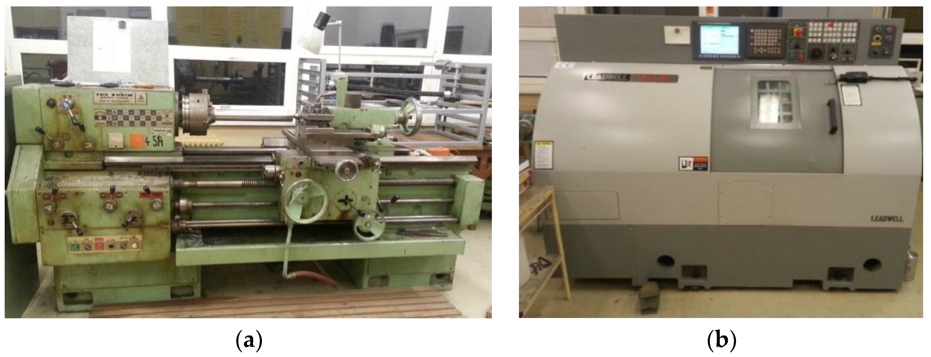
Experiments were carried out on a conventional universal tipping lathe (SU 50 A, TOS Kuřim, Kuřim, Czech Republic), as recommended by the standard and the experiments were also re-implemented on the CNC machine (Leadwell T-5, LEADWELL CNC MACHINES MFG. CORP., Taichung, Taiwan) for practice requirements. The machine tools are presented in Figure 1.
In the experiment, the conventional lathe was used for the following reasons:
- Standard provides the guide for this type of machine;
- Adequate swing diameter;
- Adequate stiffness of the machine;
- The adequate power output of the machine;
- Adequate turn range.
In the experiment, a CNC machine was used from the following reasons:
- Possibility to set the constant cutting speed;
- Adequate swing diameter;
- The adequate power output of the machine;
- Adequate turn range;
- Frequently used in practice.
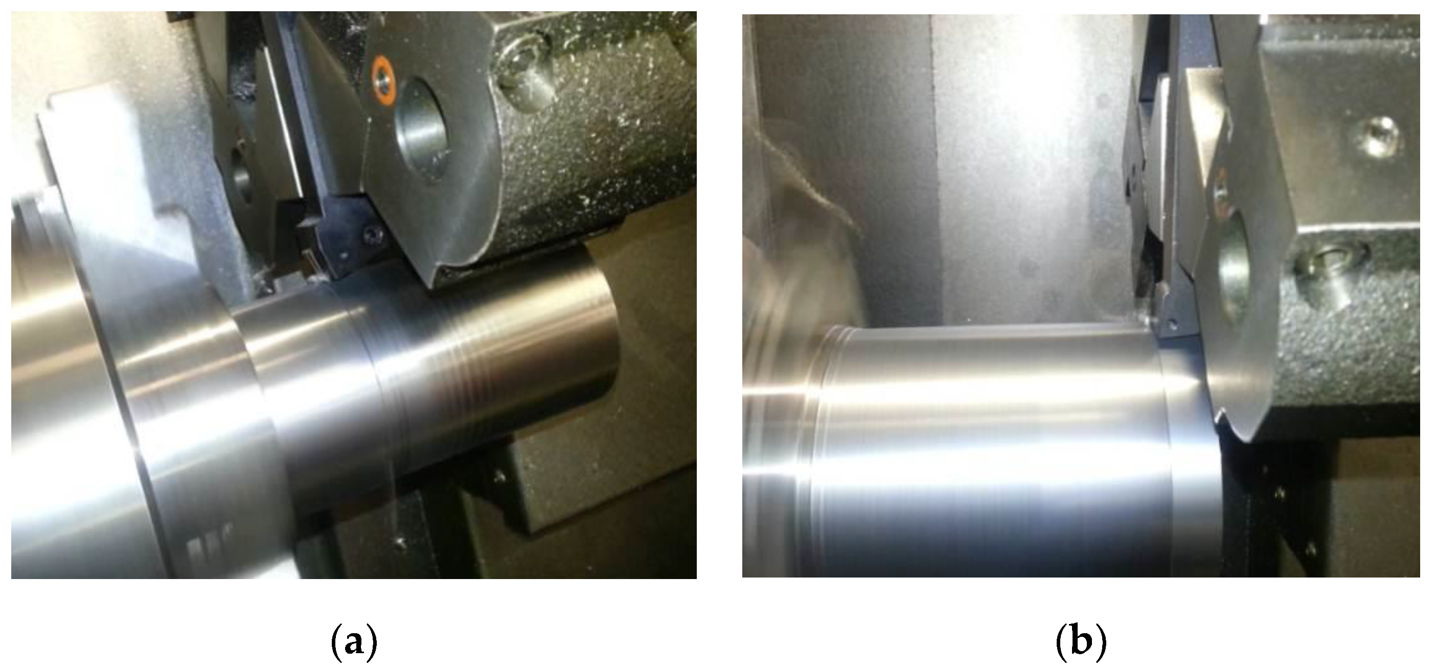
During the experiments, experimental tool and a tool for preparation of the surface was used. The experimental tool was a lathe holder with geometry, which was determined by STN ISO 3685, into which the tested cutting inserts were successively inserted. The tool for preparation of the surface was a conventional lathe holder with commonly used geometry, which was used to reprocess the surface of the machined material and ensure the same conditions for the test inserts before each transition. The view of the application of tools is presented in Figure 2.
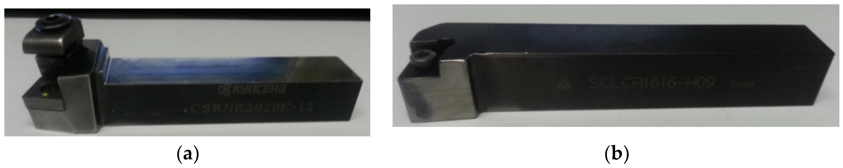
In the experiments, the CSRNR2020K-12 holder was used for the experimental tool, and the SCLCR1616-H09 holder as a tool for preparation of the surface (Figure 3), with a description of the basic properties listed in Table 1. Used tools are made by Kyocera, Hendersonville, North Carolina.
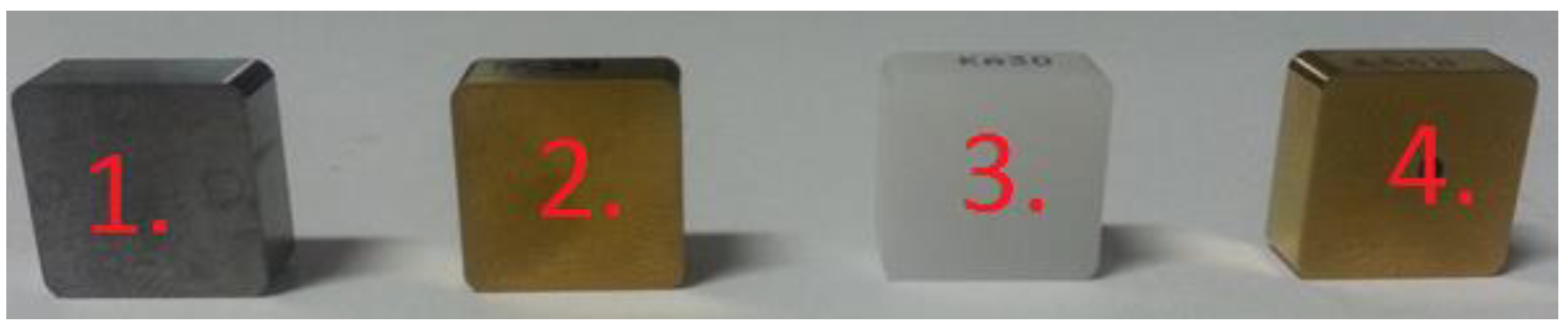
According to ISO 3685 standard, cutting tools made from high-speed steel (HSS), tungsten carbide and cutting ceramics were selected for experiments (Figure 4). The experiment was expanded with a coated modification of sintered carbide and cutting ceramics.
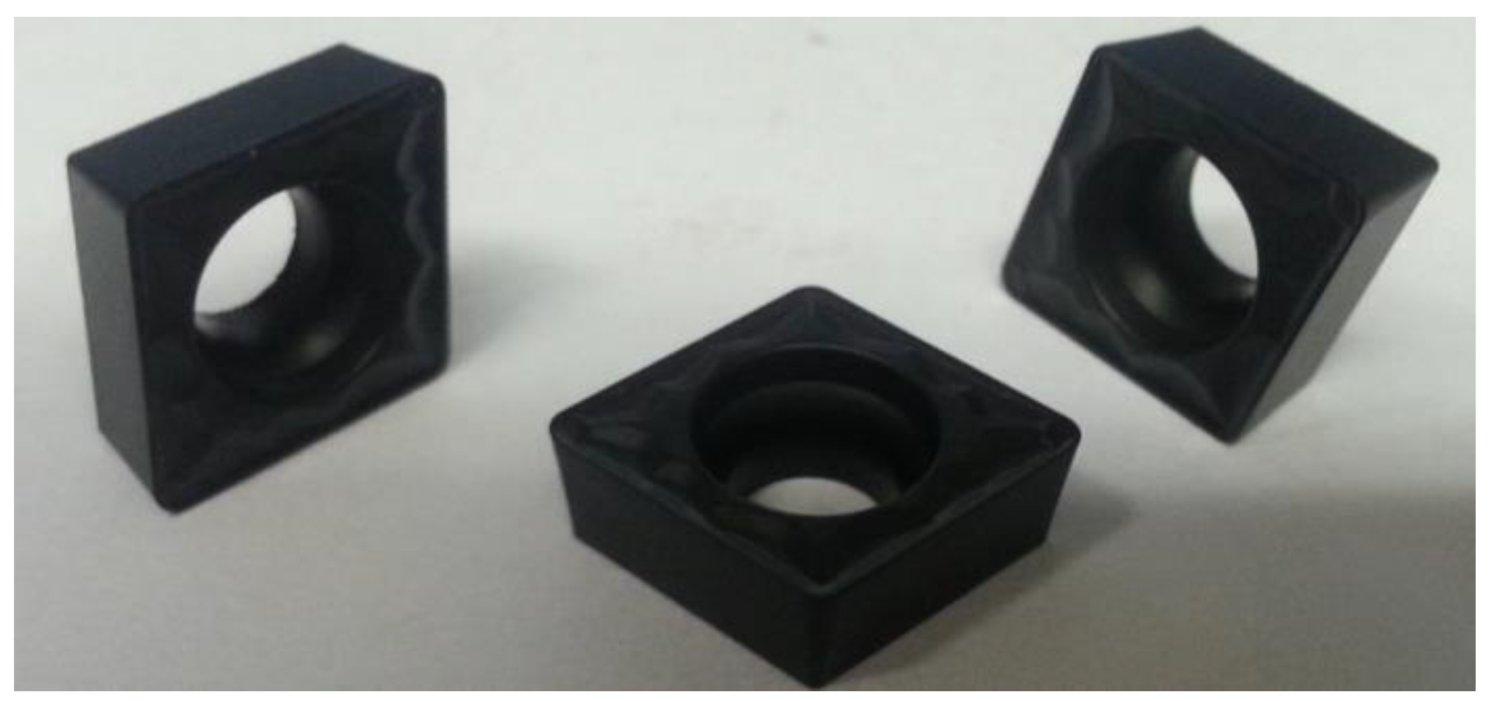
For the preparation of the tested workpieces’ surface after experimental transitions, the cutting inserts made by sintered carbide was used (Figure 5).
According to ISO 3685, C45 material was used for carrying out the experiments (Figure 6). C45 steel is medium carbon steel offering moderate tensile strengths. This material is used in the manufacturing of shafts and axles, studs and spindles, and in different engineering applications. Chemical composition and mechanical properties are presented in Table 2 and Table 3.
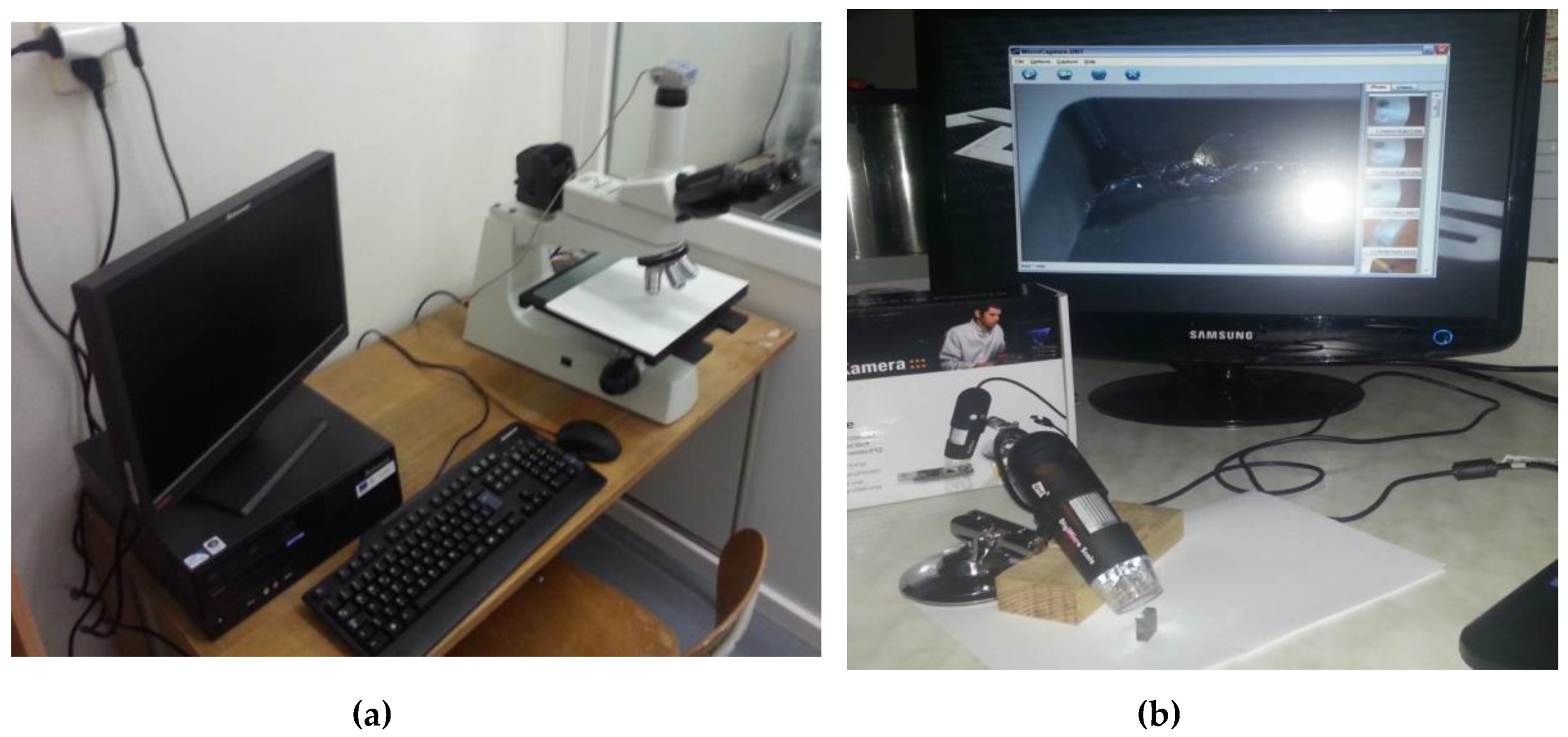
Three devices (Figure 6) were used to measure the wear of cutting tools, and thus the final evaluation of the experiment. The wear generated during machining was observed with the NJC 160 metallographic microscope (Nanjing Jiangnan Novel Optics Co., Ltd., Nanjing, China) and the DigiMicro 2.0 Scale microscope (DNT, New Taipei City, Taiwan).
During the evaluation of the experiment, the following formulas were used:
- Tool-life of cutting materials (Equation (1));
- Tool-life of cutting materials (extended formula) (Equation (2));
- Correlation index [41]:
- y’i—calculated values according the selected function for i = 1, 2, …, n
- —arithmetic mean of the measured values
- yi—measured values.
- General equation of regression:
- —independent variable
- —parameters
- —error.
3. Carrying Out of the Experiments
After the analysis of ISO 3685 standard, the following discrepancies were found:
- Limited area for recording the measured outputs of the resulting dependence;
- Common characteristics and its course for all defined cutting tools;
- Interpolation of the dependence into an unmeasured area of cutting speeds;
- Interpolation of a straight line through the measured points by estimation, or by eye.
These have been the subject and main purpose of experiments. The cutting parameters of the experiments were strictly based on ISO 3685 for machining by using conventional and CNC lathes. The cutting conditions are listed in Table 4.
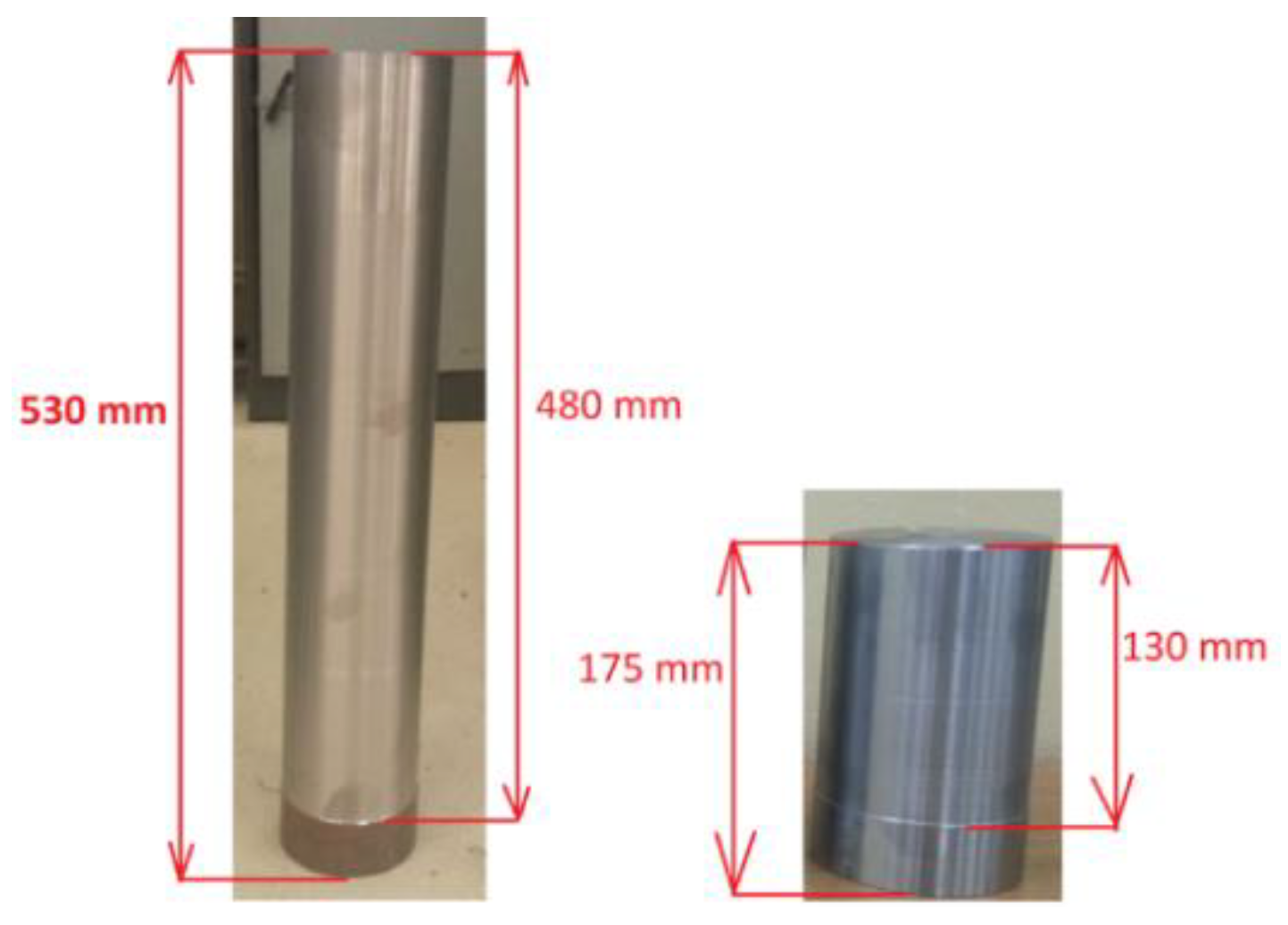
The semi-finished product was cut with a band saw to the required sample sizes for both types of machines separately. For a conventional lathe, the samples had dimensions Φ 97.5 × 530 mm and CNC lathe Φ 97.5 × 175 mm (Figure 7). After the individual samples were cut, centring holes were drilled. The centring holes were drilled on both sides of the samples due to their rotation in the chuck during preparation. The sample (Figure 7 (left)) was machined to a length of 480 mm but the whole length of sample was 530 mm due to the clamping requirement. The sample (Figure 7 (right)) was machined to a length of 130 mm but the whole length of the sample was 175 mm for the same reason.
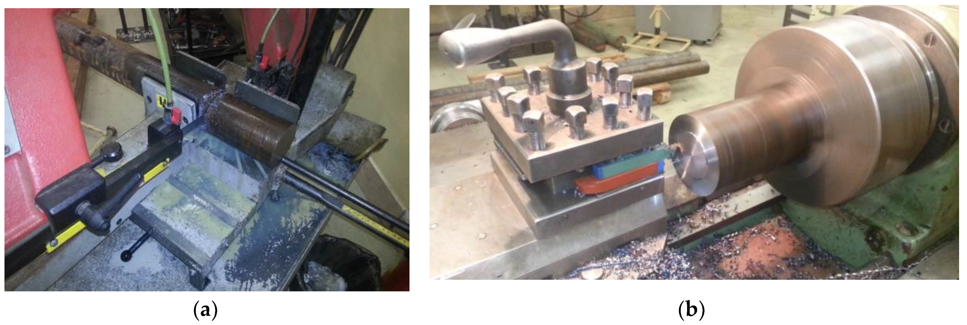
After the material was cut into experimental samples, the workpieces were then machined to the same dimensions. Gradually, on the individual samples, the faces were aligned and also the turning diameter to obtain the same dimensions and properties of the test pieces. The example of the experiment is presented in Figure 8.
After that, the test sample was tightened to the chuck using a deviation device to prevent the creation of the incomplete cylindrical surface. Subsequently, the experimental samples were rounded to the same diameter also to ensure the same initial properties. After performing the defined operations, individual pieces were prepared for CNC lathe experiments.
Based on the available speed and also the known cutting speed, the diameters for the cutting speed under investigation were derived, which could be turned into one experimental sample. The Table 5 shows a sample of the relevant data, based on which the T-vc diagram was compiled.
After setting the required speed and defined travel speed, the depth of cut was also preset. When the machine was switched on, the stopwatch was also switched on. After 5 min, the machine was stopped; the cutting insert was taken out. Through the microscope, the cutting insert was recorded and the current state of wear of the cutting tool’s back was measured. This process was repeated until the prescribed wear VB = 0.3 mm was achieved. If wear occurred between the intervals of two measurements, i.e., during a five-minute unmarked interval, formula (1) was used to determine the exact time of wear. However, if the wear was not yet sufficient, it was measured, recorded and the experiment continued.
An experiment to obtain complex T-vc dependence for selected cutting materials was performed on a CNC Leadwell T-5 lathe using a CNC program that was designed by the FANUC control systemproduced by Fanuc corporation, Oshino-mura, Yamanashi Prefecture Japan. The experiment was performed by turning the surface on an experimental instrument at a specific diameter, and then, after replacing the tool, the test piece was pre-calibrated to ensure a constant condition for all transitions, tools and cutting speeds. The cutting parameters for the comparison tool were not changed throughout the experiment. Table 6 provides a sample of the calculations required to run the experiment.
As with experiments on a conventional lathe, the experiments were performed five times for each tested cutting tool, each time a single cutting insert was inserted into the holder.
4. Prediction of Cutting Material Durability
After performing all the defined experiments on both machine types, the results were marked in a linear and logarithmic scale in accordance with the ISO 3685 standard. To determine the durability of cutting materials for Taylor dependence, the application of the least-squares method was also proposed, as well as the regression analysis.
4.1. Design of Data Processing by the Least-Squares Method
By using the least-squares method, the analytical relations for all experimentally tested cutting materials were sequentially calculated. The following Table 7 shows the complex T-vc dependence of all cutting materials that have been experimentally tested on a conventional lathe.
Based on values (Table 7), all analytical derivations of the investigated dependence on the correlation index were determined. After obtaining complete analytical derivations and correlation indexes of the tested cutting materials for the conventional lathe, the formulas were overwritten to form T-vc, so y was replaced by T and x2 was replaced with vc, Table 8. There was one more parameter in the formula, and it was determined as the KRM—constant of used cutting material. This parameter was determined as the second most important factor influencing durability. Other factors were constant (feed rate, depth of cut, tool geometry). If the calculated formulas contained other parameters, these parameters were ignored as their values were close to zero (e.g., 10−8), so even after inserting specific data into the formula, the value was still ignored.
Using the least-squares method, the analytical derivations with a calculated correlation index were created for all tested cutting materials on a conventional lathe. By performing the analysis of the results achieved, it can be observed that depending on high-speed steel and tungsten carbide, it is a functional dependency (I > 90%) and for other cutting tools a very significant degree of statistical dependency (0.50 ≤ │I│ < 0.90).
The method was also applied to experiments to obtain T-vc dependence that was performed on a CNC lathe. In Table 9 and Table 10, the T-vc dependences and equations created by the least-squares method is presented.
By obtaining the formulas describing all tested cutting tools, as in the previous case, the shapes of the equations were transcribed into T-vc dependencies.
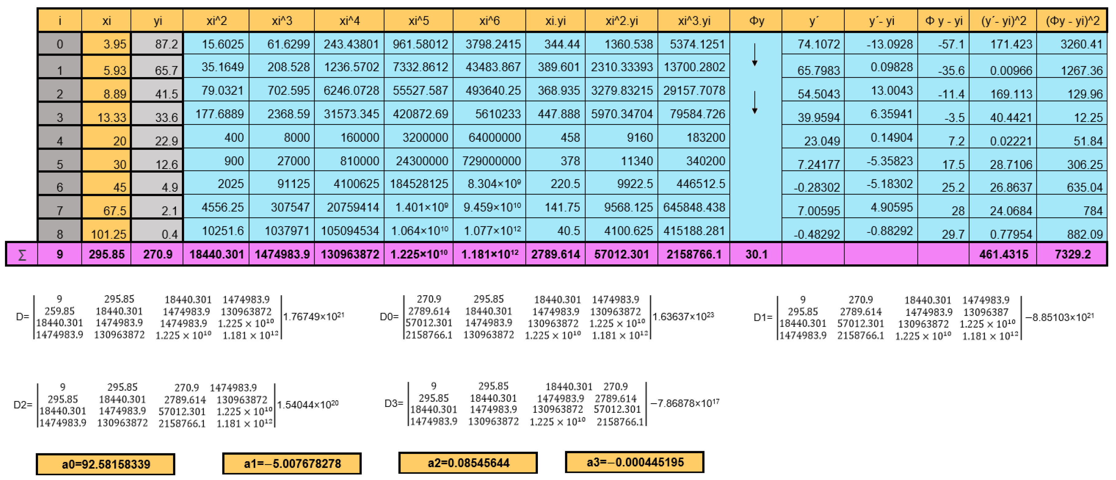
For all cutting materials, formulas of the dependence were created and determined on the experiments performed on the conventional lathe and CNC machine. Demonstration of data calculation by the least-squares methods in MS Excel is presented in Figure 9. Finally, the analytical expression of the studied dependence was also derived for all cutting materials on both machine types together, however, in terms of the least-squares method principle, the resulting correlation index was less than 50%, mainly due to a large number of values corresponding to the respective coordinate (ten different durations corresponding to one cutting speed.). The final formula is presented in the following equation:
4.2. Design of Data Processing by the Regression Analysis
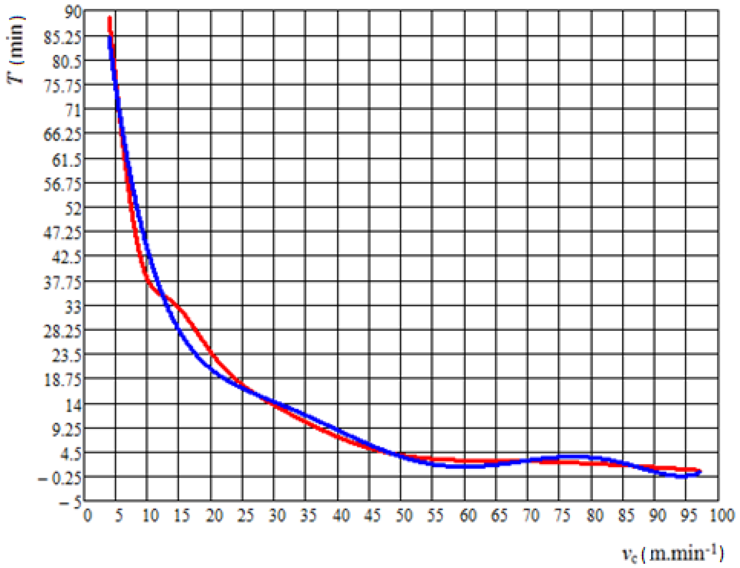
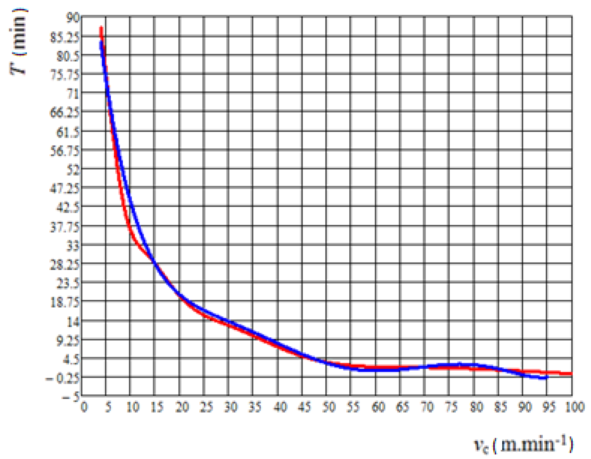
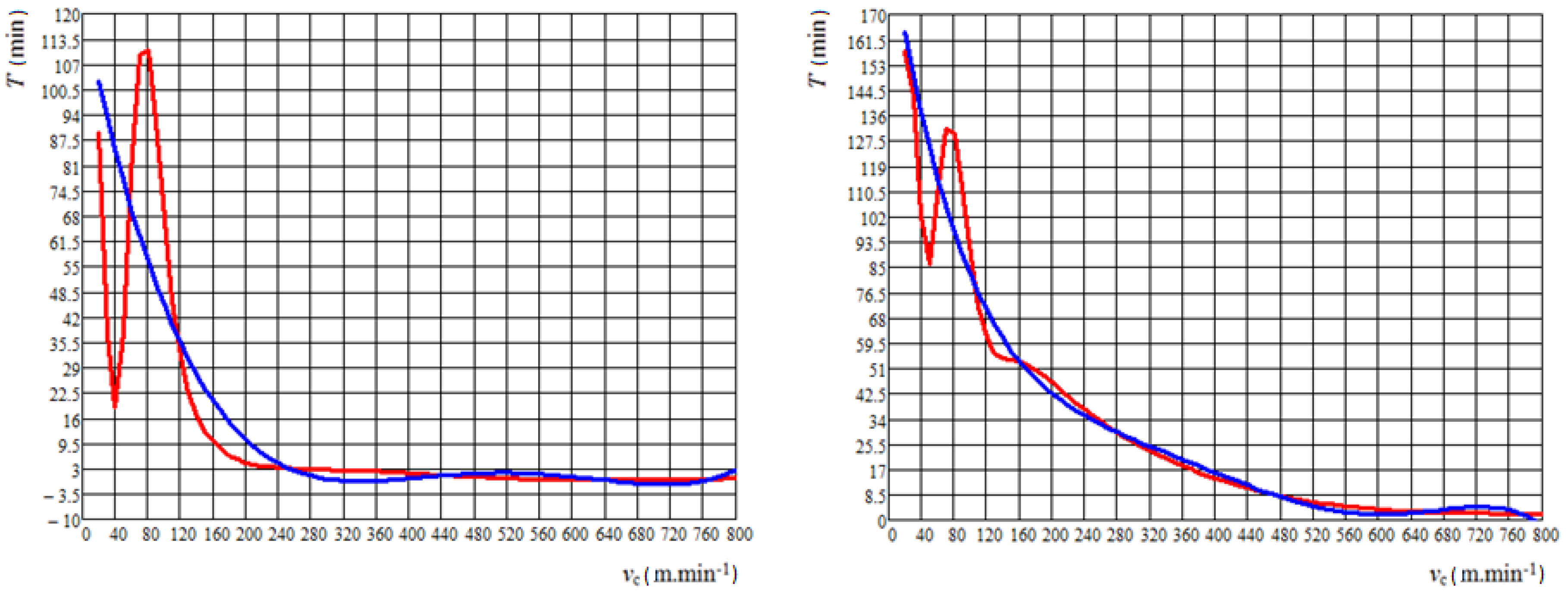
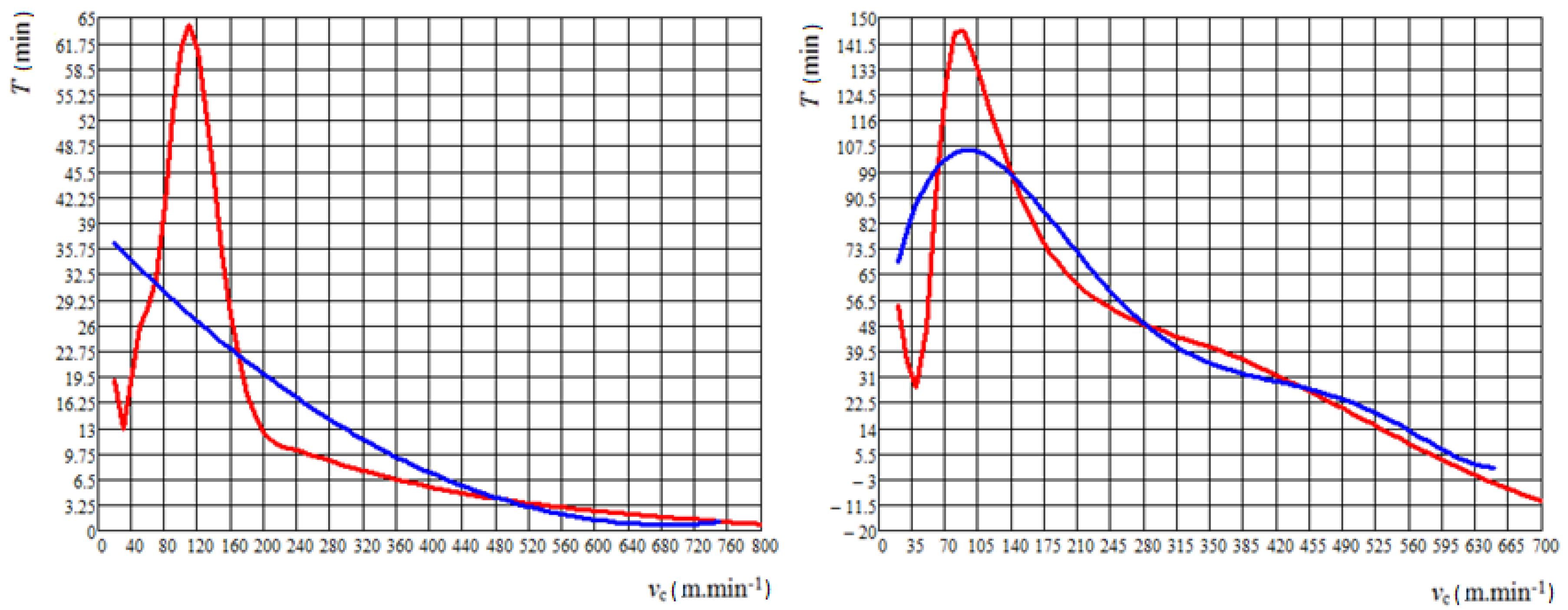
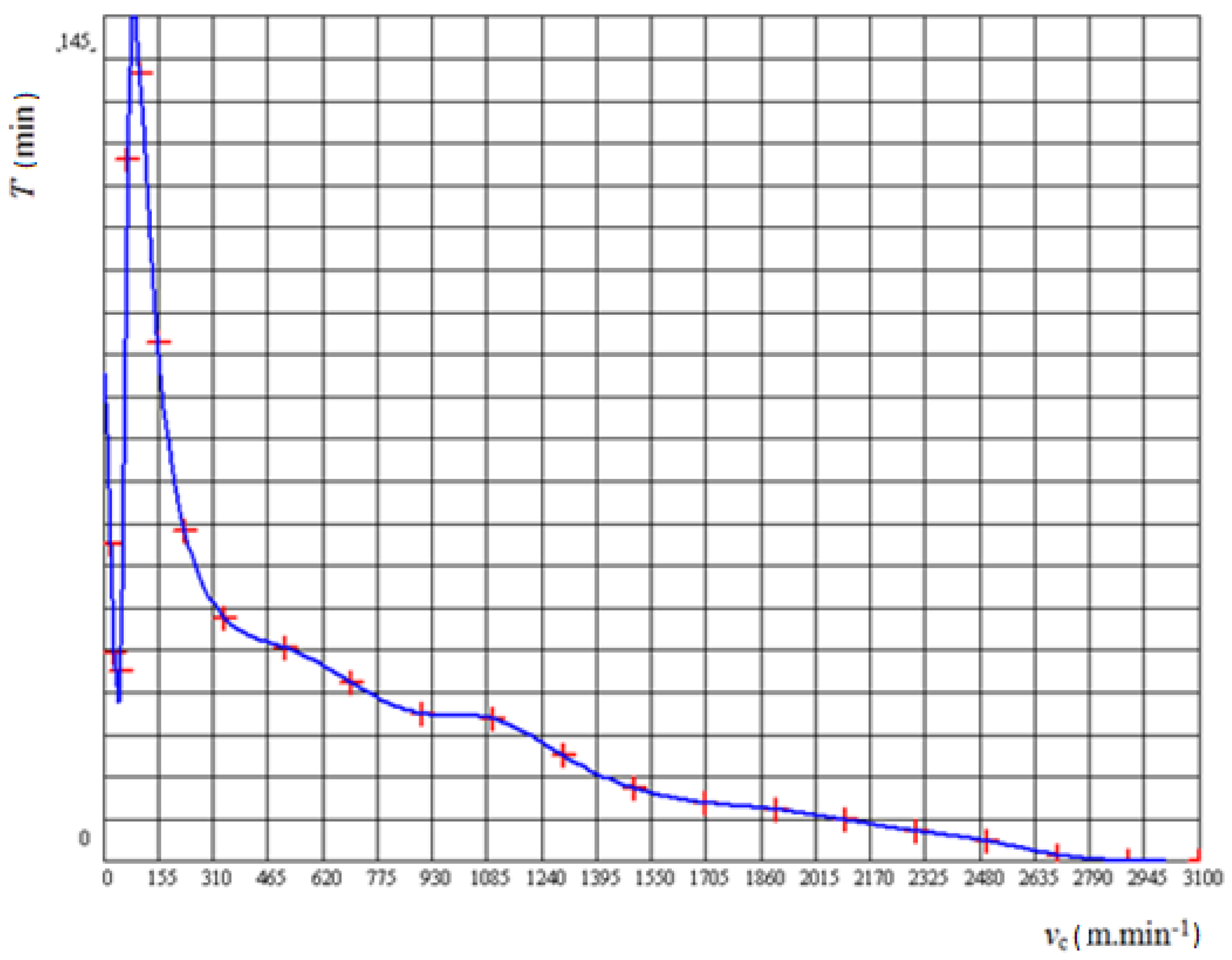
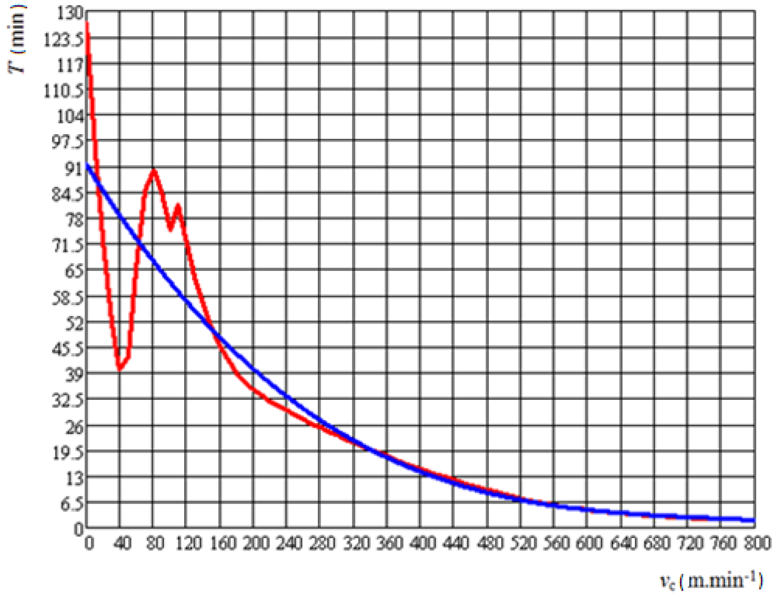
Due to the low correlation index values, another method of processing the measured values and the subsequent analytical representation of observed dependencies was also proposed. The regression analysis by the Mathcad software is a comprehensive set of functions that just optimizes the method selection according to the inputs, and thus can more accurately express the dependence. Another advantage of this software is to predict the behaviour of the cutting tool based on the inputs entered and to perform a regression analysis to estimate its overall service life. The following graphs (Figure 10, Figure 11 and Figure 12) present two curves: red curve—values obtained from experiment and blue curve—values determined in accordance with ISO 3685.
Processing of the measured values using the regression analysis in MathCad 14 software produced by PTC, Boston, MA, United States obtained analytical representations of the obtained waveforms, which are presented in Table 11.
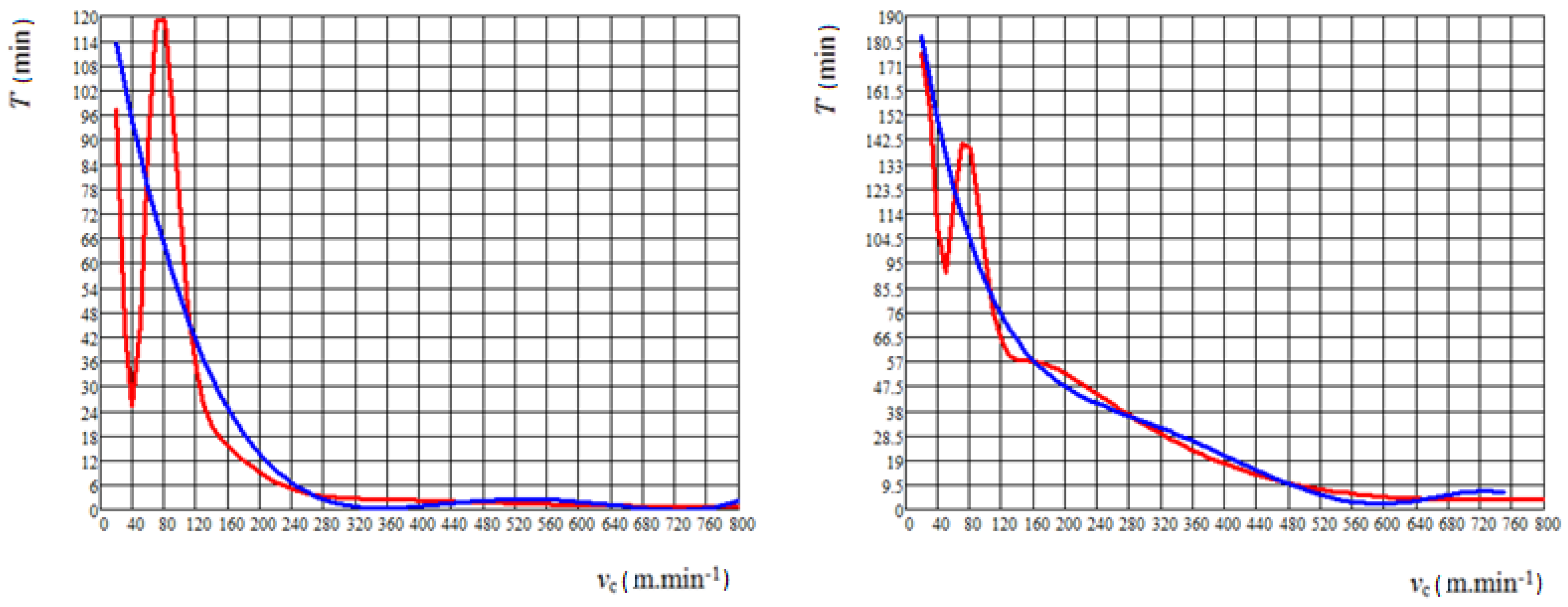
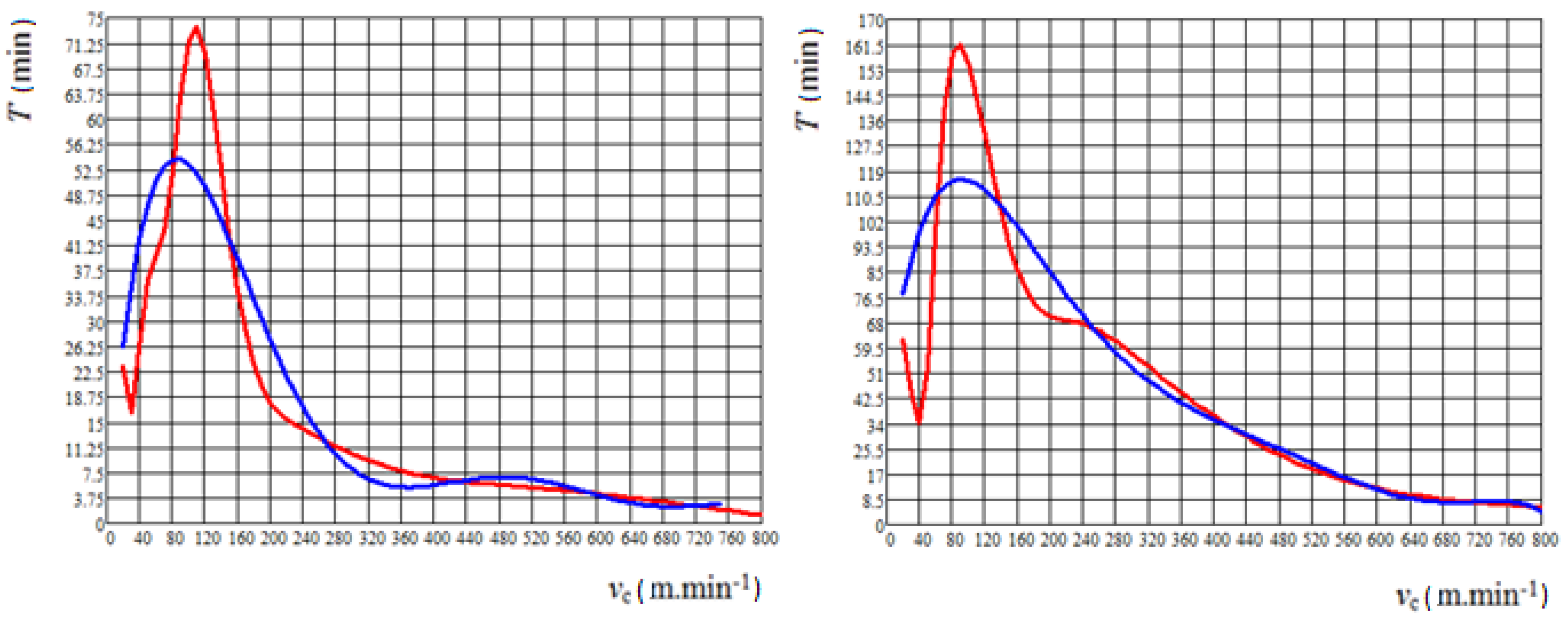
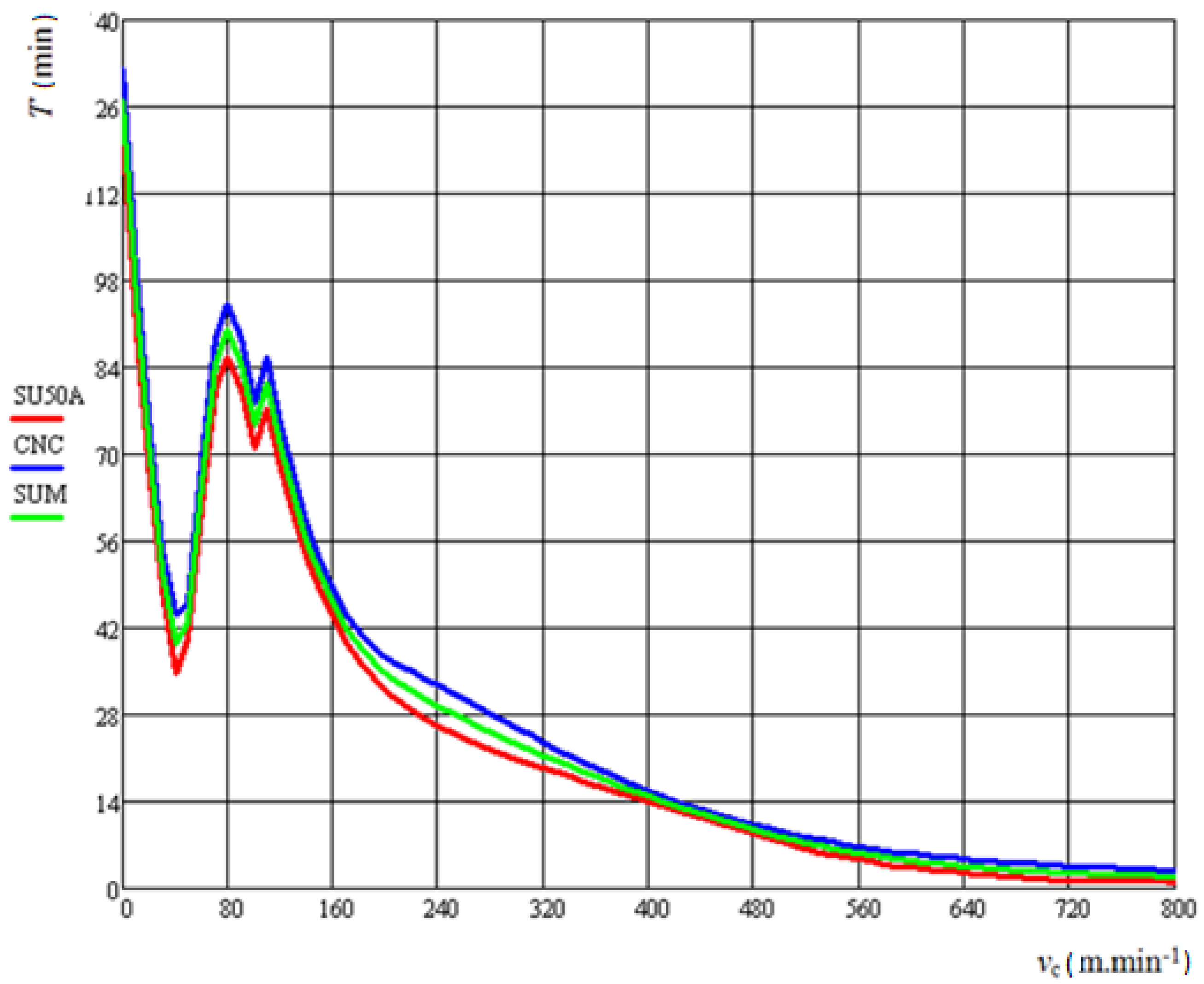
By comparing the previous results with the results obtained by the regression analysis method, it is clear that by this method the correlation indexes in each of the solved cases are above the 90% threshold, and thus the given analytical expression of T-vc dependence can be said to be a functional relationship for a given type of used technological parameter. The method was further applied sequentially to all the results obtained in CNC machine experiments; it was used for all tested cutting materials. The regression analysis of T-vc dependence is presented in Figure 13, Figure 14 and Figure 15.
Figure 11, Figure 12, Figure 14 and Figure 15 show the red line values obtained from the experiment. In the area of lower cutting speeds (maximum for value up to 100 m/min) an increase in durability was recorded, due to the range of optimal cutting parameters for the given cutting tools. Subsequently, for cutting speeds with values higher than 100 m/min, a decrease in durability was recorded due to the values of the cutting parameters different from the optimal values. However, the aim of the experiments was to describe the whole course of available cutting parameters, not just optimal ones.
Using the regression analysis method in Mathcad, the cutting materials were separately tested and the analytical expressions of observed dependence also created, followed by correlation indexing, Table 12.
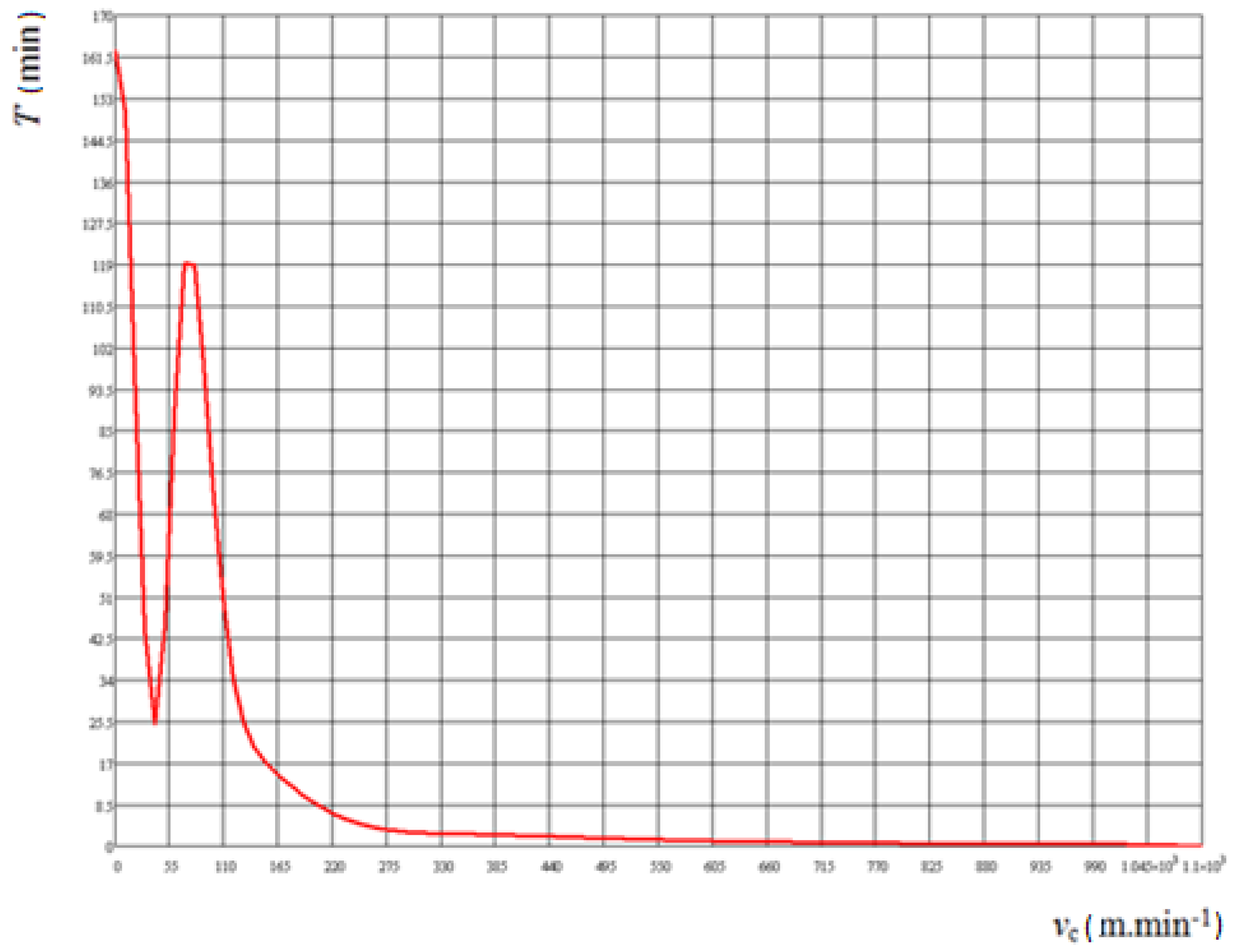
In addition to evaluating input data, the software can predict further behaviors of a specified set of values, which is just predicting the durability of the cutting tool in the machining process with the specified technological parameters. In the following two graphs (Figure 16 and Figure 17), such predictions are presented, so it is possible to determine when the cutting tool reaches zero durability, that is, at what cutting speed it is no longer able to functionally machine with the input technological parameters and the determined wear criterion.
The final step, which was performed in the evaluation and determination of analytical T-vc dependence by the regression analysis method in Mathcad software, the determination of the resulting regression line for all tested cutting materials on both types of machines in the experiment was used. The process consisted of applying all the results from the individual measurements for both tested machines and all used cutting tools into one common graph, where one curve characterized the resulting T-vc dependence on cutting tools tested on a conventional lathe and the other line characterized the resulting T- depending on the cutting tools tested on the CNC machine.
From these graphs, the cumulative diameter was obtained, as presented by the graph in Figure 18, and the regression line presented in Figure 19 was then created with this summed mean. The regression line thus constructed was then assigned an equation that characterized the course of this line as well as with a corresponding correlation index. The relationship that was established was the rule of the resulting T-vc dependence of the experiment.
The comprehensive formula for T-vc dependence:
In the obtained analytical formulas, one constant was created, which influenced the functionality of the whole formula and the dependence itself most. It was marked as KRM. It is the constant of the cutting tool. The obtained dependence was experimentally verified on only one type of machined material, on the C45 steel. It is possible to assume that the change of the material to be machined would also increase its constant.
In the following Table 13, the basic values of the KRM constant are presented and can be matched to the obtained dependencies for determining the durability (T-vc dependence).
5. Results and Discussion
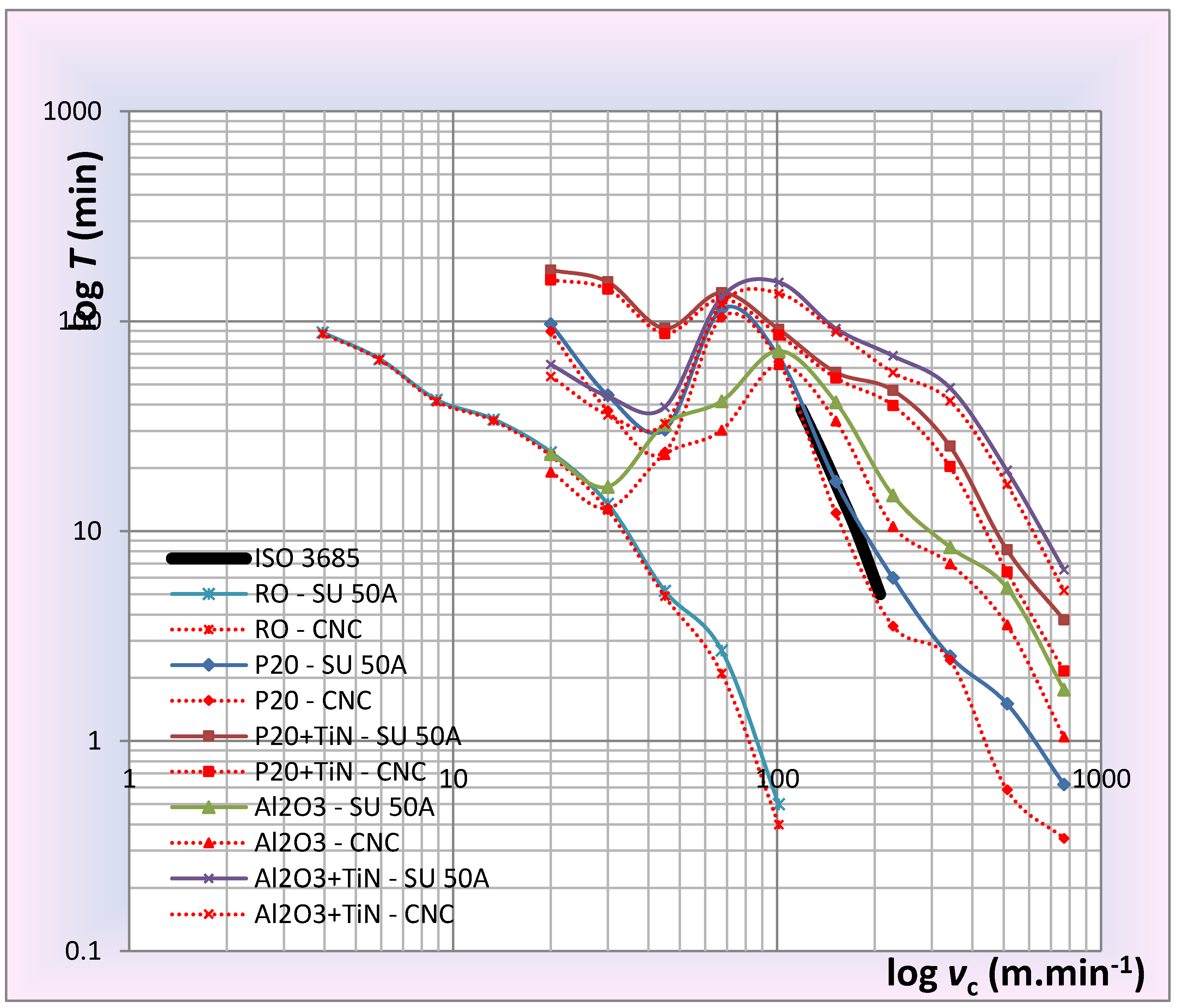
Due to the results of the experiments, it is evident that the statement of the STN ISO 3685 standard, which states that the cutting tool life depends on the cutting speed has a linear course in the logarithmic scale is not true. The standard outside of the measured areas recommends that the lines be extended, since the measurements were not performed, only estimated, which it is also not the correct recommendation given the results of the experiment. In Figure 20, the comprehensive T-vc dependence for all tested cutting materials in logarithmic scale is presented.
The shape of comprehensive T-vc dependence is an array of line segments or lines, but in any case, it cannot be a single line because at the minimum cutting speed the shelf life would be several hours, which is also inconsistent with the experiments. The standard defines, for each cutting material, that it contains one common dependence that distinguishes it only by the different rake of the given line. This is also false with regard to the results because the structural composition of the type of different cutting materials, such as, for example, tungsten carbide and cutting ceramics, and therefore the statement and recommendation of the standard cannot be true at this point either. In terms of evaluating the experimentally obtained values, the standard recommends the evaluation by the eye, the least-squares method, or the extension of the resulting line to unmeasured areas, which, given the fact that the resulting dependence on the logarithmic scale would be linear, was sufficient, but referring to the results of the experiments, two methods of evaluating the results, namely the least-squares method (due to the recommendation of the standard) and the regression analysis method in Mathcad (because it is considered more accurate due to a large number of automatic computational procedures of the program). In the previous parts of the article, all partial analytical formulas were specified, from which the resulting relationships characterizing the dependencies were created for both proposed methods.
- The least-squares method:
- Regression analysis:
According to analytical expressions, there is a more accurate regression analysis method, where the correlation index is 93.5%, which explains the functional dependence of the given formula.
6. Conclusions
The presented article was focused on the proposal of mathematical methods for the durability of cutting materials by using the dependence T = f (vc). By implementing the defined experiments and deriving the analytical expressions of the individual dependencies, functional rules of the behaviour of the cutting tool in the machining process were created in terms of its durability. The general mathematical prescription was evaluated based on average values for each vc and subsequently was calculated general equation based on mean values from the experimental part to obtain the equation for posterior estimation of durability but only with informative character due to different types of cutting material. In practice, it means that the operation can fast calculate estimated durability time in the case do not know the exact composition of the material. Based on the formulas, it is possible to predict the behaviour of the cutting tool in the machining process and thus to predetermine the machining time of the selected cutting edge, which can serve to improve the logistics in the manufacturing process in designing the technological processes. The possible further improvement of this model consists of the expansion of formula by other variables. The point of the research was to generalize the prescription for durability within the examined cutting materials for the turning process. Further research is being done to study other influences and parameters related to the process. The process is also being extended to other materials.
Carrying out the experiments described in this article brings the following benefits:
- Comprehensive knowledge of the T-vc dependence for the most commonly used cutting tools;
- Analytical description of experimental measurements;
- Experimental invalidity confirmation of ISO 3685;
- Through analytical expressions, it provides a proposal for correcting the standard used today by manufacturing companies;
- Identification of optimum cutting speed in terms of maximum tool life;
- Prediction of the behaviour of the cutting tool in the machining process.
Another investigation of this issue is extremely important and highly topical, as only one material, namely C45 steel, was tested in this work. In the future, it would be advisable to extend the knowledge of other technical materials. The consistent comprehensive knowledge of the durability of the cutting tool and the determination of cutting parameters based on the tool’s optimum durability is of significant importance in terms of the efficient economy of the manufacturing plants.
Author Contributions
Conceptualization, J.D.; Data curation, D.D., P.C., I.O. and A.B.; Formal analysis, J.D.; Investigation, J.D.; Methodology, J.Z. and J.D.; Writing, D.D. All authors have read and agreed to the published version of the manuscript.
Funding
This research was funded by research projects VEGA 1/0682/17, KEGA 025TUKE-4/2018 granted by the Ministry of Education, Science, Research and Sport of the Slovak Republic and by the Project of the Structural Funds of the EU, ITMS code: 26220220103.
Conflicts of Interest
The authors declare no conflicts of interest.
References
- Nicolich, M. Experimental Test for Tool-Life Prediction in Turning. CISM Cour. L 2002, 437, 185–192. [Google Scholar]
- Straka, Ľ.; Čorný, I.; Pite’, J. Prediction of the geometrical accuracy of the machined surface of the tool steel EN X30WCrV9-3 after electrical discharge machining with CuZn37 wire electrode. Metals 2017, 7, 462. [Google Scholar] [CrossRef] [Green Version]
- Valíček, J.; Harničárová, M.; Öchsner, A.; Hutyrová, Z.; Kušnerová, M.; Tozan, H.; Michenka, V.; Sepelak, V.; Mital, D.; Zajac, J. Quantifying the mechanical properties of materials and the process of elastic-plastic deformation under external stress on material. Materials 2015, 8, 7401–7422. [Google Scholar] [CrossRef] [Green Version]
- Knapčíková, L.; Dupláková, D.; Radchenko, S.; Hatala, M. Rheological behavior modelling of composite materials used in engineering industry. TEM J. 2017, 6, 242–245. [Google Scholar]
- Hutyrová, Z.; Harničarová, M.; Zajac, J.; Valíček, J.; Mihok, J. Experimental study of surface roughness of wood plastic composites after turning. Adv. Mater. Res. 2014, 856, 108–112. [Google Scholar] [CrossRef]
- Batista, M.; Davim, P.; Salguero, J.; Gomez-Parra, A.; Marcos, M. Taylor’s Model Based Analysis of Turning Inserts Tool-Life in the Dry Turning of UNS R56400 Alloy. In ASME 2014 International Mechanical Engineering Congress and Exposition; American Society of Mechanical Engineers: New York, NY, USA, 2014. [Google Scholar]
- Díaz, R.C.; Krahmer, D.M.; vila Rondón, R. Application of ISO 3685 in the evaluation of the machinability of steel SAE 1020 during the turning process. Rev. Tec. Fac. Ing. Univ. 2011, 34, 194–202. [Google Scholar]
- Dhabale, R.; Jatti, V.S.; Singh, T.P. Optimization of turning process during machining of AlMg1SiCu using Taguchi method and ANOVA. Int. J. Appl. Eng. Res. 2013, 8, 1273–1281. [Google Scholar]
- Chethan, Y.D.; Ravindra, H.V.; Krishnegowda, Y.T. Optimization of machining parameters in turning Nimonic-75 using machine vision and acoustic emission signals by Taguchi technique. Measurement 2019, 144, 144–154. [Google Scholar] [CrossRef]
- Dubovska, R.; Majerik, J.; Chochlikova, H. Investigation of Durability T = f (vc) in Turning of the AISI 304 Austenitic Stainless Steel using the CNMG 120408 Coated Carbide Insert. Adv. Mater. Res. 2014, 941, 1633–1643. [Google Scholar] [CrossRef]
- Iliescu, M. Cutting tool durability regression models in turning Inox 18-8 thermal sprayed coating. ACAD J. Manuf. Eng. 2011, 9, 61–66. [Google Scholar]
- Iliescu, M. Regression models of process parameters interdependence in turning S12Mn2Si metallized coatings. Wseas Trans. Syst. 2011, 10, 319–330. [Google Scholar]
- Miani, F.; Guseo, R.; Mortarino, C.; Meneghello, R. A new proposal for tool-life analysis: Response surface modelling of the flank wear progression. In Proceedings of the 2nd International Seminar on Improving Machine Tool Performance, La Baule, Nantes, France, 3–5 July 2000; pp. 3–5. [Google Scholar]
- Nath, C.; Brooks, Z.; Kurfess, T.R. Machinability study and process optimization in face milling of some super alloys with indexable copy face mill inserts. J. Manuf. Process. 2015, 20, 88–97. [Google Scholar] [CrossRef]
- Petru, J.; Schiffner, J.; Zlamal, T.; Cep, R.; Kratochvil, J.; Stancekova, D. Wear progress of exchangeable cutting inserts during Ti (6) Al (4) V alloy machining. In Proceedings of the 24th International Conference on Metallurgy and Materials, Brno, Czech Republic, 3–5 June 2015; pp. 1147–1155. [Google Scholar]
- Qehaja, N.; Kyçyku, A. Tool life modeling based on cutting parameters and work material hardness in turning process. Scientific proceedings XIV international congress. Mach. Technol. Mater. 2017, 11, 356–359. [Google Scholar]
- Sadílek, M.; Kratochvíl, J.; Petrů, J.; Čep, R.; Zlámal, T.; Stančeková, D. Cutting tool wear monitoring with the use of impedance layers. Vjesnik 2014, 21, 639–644. [Google Scholar]
- Čep, R.; Janásek, A.; Martinický, B.; Sadílek, M. Cutting tool life tests of ceramic inserts for car engine sleeves. Vjesnik 2011, 18, 203–209. [Google Scholar]
- Majernikova, J.; Spisak, E. Increasing durability of cutting tools. Adv. Sci. Technol. Res. J. 2017, 11, 141–146. [Google Scholar]
- Bakša, T.; Kroupa, T.; Hanzl, P.; Zetek, M. Durability of cutting tools during machining of very hard and solid materials. Procedia Eng. 2015, 100, 1414–1423. [Google Scholar] [CrossRef] [Green Version]
- Chaus, A.S.; Rudnitskii, F.I. Influence of cutting conditions of cast-metal cutting tools on their wear and durability: Analysis of cutting conditions of tools. J. Frict. Wear 2007, 28, 416–421. [Google Scholar] [CrossRef]
- Chaus, A.S.; Rudnitskii, F.I. Influence of cutting conditions of cast-metal cutting tools on their wear and durability. Part 2. Durability test results. J. Frict. Wear 2008, 29, 151–155. [Google Scholar] [CrossRef]
- Gill, S.S.; Singh, H.; Singh, R.; Singh, J. Flank wear and machining performance of cryogenically treated tungsten carbide inserts. Mater. Manuf. Process. 2011, 26, 1430–1441. [Google Scholar] [CrossRef]
- Gill, S.S.; Singh, J.; Singh, H.; Singh, R. Investigation on wear behaviour of cryogenically treated TiAlN coated tungsten carbide inserts in turning. Int. J. Mach. Tools Manuf. 2011, 51, 25–33. [Google Scholar] [CrossRef]
- Caballero, J.E.; V-Niño, E.D. Wear evaluation of flank in burins of high speed steel modified with titanium ions. J. Phys. Conf. Ser. 2017, 935, 1–5. [Google Scholar] [CrossRef]
- Hao, X.; Chen, X.; Xiao, S.; Li, L.; He, N. Cutting performance of carbide tools with hybrid texture. Int. J. Adv. Manuf. Technol. 2018, 97, 3547–3556. [Google Scholar] [CrossRef]
- Jaworski, J.; Trzepieciński, T. Research on durability of turning tools made of low-alloy high-speed steel. Met. Mater. 2016, 54, 17–25. [Google Scholar] [CrossRef] [Green Version]
- Lalbondre, R.; Krishna, P.; Mohankumar, G.C. Machinability studies of low alloy steels by face turning method: An experimental investigation. Procedia Eng. 2013, 64, 632–641. [Google Scholar] [CrossRef]
- Neshta, A.; Kryvoruchko, D.; Hatala, M.; Ivanov, V.; Botko, F.; Radchenko, S.; Mital, D. Technological Assurance of High-Efficiency Machining of Internal Rope Threads on Computer Numerical Control Milling Machines. J. Manuf. Sci. Eng. 2018, 140, 1–8. [Google Scholar] [CrossRef]
- Holub, M.; Jankovych, R.; Andrs, O.; Kolibal, Z. Capability assessment of CNC machining centres as measuring devices. Measurement 2018, 118, 52–60. [Google Scholar] [CrossRef]
- Che-Haron, C.H. Tool life and surface integrity in turning titanium alloy. J. Mater. Process. Technol. 2001, 118, 231–237. [Google Scholar] [CrossRef]
- Yip, W.S.; To, S. Tool life enhancement in dry diamond turning of titanium alloys using an eddy current damping and a magnetic field for sustainable manufacturing. J. Clean. Prod. 2017, 168, 929–939. [Google Scholar] [CrossRef]
- Ren, Z.; Qu, S.; Zhang, Y.; Sun, F.; Li, X.; Yang, C. Machining performance of PCD and PCBN tools in dry turning titanium alloy Ti-6Al-0.6 Cr-0.4 Fe-0.4 Si-0.01 B. Int. J. Adv. Manuf. Technol. 2019, 102, 2649–2661. [Google Scholar] [CrossRef]
- Kamruzzaman, M.; Rahman, S.S.; Ashraf, M.Z.I.; Dhar, N.R. Tool life and workpiece surface integrity when turning an RR1000nickel-based superalloy. Int. J. Adv. Manuf. Technol. 2018, 98, 2461–2468. [Google Scholar]
- Antonialli, A.Í.S.; Magri, A.; Diniz, A.E. Tool life and tool wear in taper turning of a nickel-based superalloy. Int. J. Adv. Manuf. Technol. 2016, 87, 2023–2032. [Google Scholar] [CrossRef]
- Priarone, P.C.; Klocke, F.; Faga, M.G.; Lung, D.; Settineri, L. Tool life and surface integrity when turning titanium aluminides with PCD tools under conventional wet cutting and cryogenic cooling. Int. J. Adv. Manuf. Technol. 2016, 85, 807–816. [Google Scholar] [CrossRef]
- Da Silva, R.B.; Sales, W.F.; Costa, E.S.; Ezugwu, E.O.; Bonney, J.; Da Silva, M.B.; Machado, Á.R. Surface integrity and tool life when turning of Ti-6Al-4V with coolant applied by different methods. Int. J. Adv. Manuf. Technol. 2017, 93, 1893–1902. [Google Scholar] [CrossRef]
- Bonfá, M.M.; Costa, É.S.; Sales, W.F.; Amorim, F.L.; Maia, L.H.A.; Machado, Á.R. Evaluation of tool life and workpiece surface roughness in turning of AISI D6 hardened steel using PCBN tools and minimum quantity of lubricant (MQL) applied at different directions. Int. J. Adv. Manuf. Technol. 2019, 103, 971–984. [Google Scholar] [CrossRef]
- Verma, J.K.; Bartarya, G.; Bhaskar, J. Effect of Minimum Quantity Lubrication on Tool Wear and Surface Integrity During Hard Turning of EN31 Steel. In Advances in Forming, Machining and Automation; Shunmugam, M., Kanthababu, M., Eds.; Lecture Notes on Multidisciplinary Industrial Engineering; Springer: Singapore, 2019. [Google Scholar]
- Sulaiman, M.A.; Asiyah, M.S.; Shahmi, R.; Mohamad, E.; Mohamad, N.A.; Ali, M.M.; Yuniawan, D.; Ito, T. Effect of cutting parameter on the tool life of the uncoated carbide tool during turning using minimum quantity lubrication (MQL). Int. J. Adv. Manuf. Technol. 2019, 12, 63–72. [Google Scholar]
- Straka, Ľ.; Čorný, I.; Piteľ, J.; Hašová, S. Statistical Approach to Optimize the Process Parameters of HAZ of Tool Steel EN X32CrMoV12-28 after Die-Sinking EDM with SF-Cu Electrode. Metals 2017, 7, 35. [Google Scholar] [CrossRef] [Green Version]
Figure 1.
Machine tools: SU 50 A (a) a CNC Leadwell T-5 (b).

Figure 2.
Application of experimental tool (a) and tool for preparation of surface (b).

Figure 3.
CSRNR2020K-12 (a) and SCLCR1616-H09 (b).

Figure 4.
Cutting inserts (1) P20—Sintered carbide; (2) P20 + TiN—Sintered carbide with a standard coat—Korloy company; (3) Al2O3—Cutting ceramics; (4) Al2O3 + TiN—Cutting ceramics with a standard coat—Korloy company.
Figure 4.
Cutting inserts (1) P20—Sintered carbide; (2) P20 + TiN—Sintered carbide with a standard coat—Korloy company; (3) Al2O3—Cutting ceramics; (4) Al2O3 + TiN—Cutting ceramics with a standard coat—Korloy company.

Figure 5.
Cutting inserts used for the preparation of the tested workpieces.

Figure 6.
NJC 160 metallographic microscope (a) and Digi Micro 2.0 Scale microscope (b).

Figure 7.
Samples for experiments –conventional lathe sample (left), CNC lathe (right).

Figure 8.
Carrying out of experiments – material cutting (a), face alignment (b).

Figure 9.
Demonstration of data calculation by the least-squares method (MS Excel).

Figure 10.
Regression analysis of T-vc dependence for HSS—conventional lathe (red curve—values obtained from experiment; blue curve—values determined in accordance with ISO 3685).
Figure 10.
Regression analysis of T-vc dependence for HSS—conventional lathe (red curve—values obtained from experiment; blue curve—values determined in accordance with ISO 3685).

Figure 11.
Regression analysis of T-vc dependence for P20 (left) and P20+TiN (right)—conventional lathe (red curve—values obtained from the experiment; blue curve—values determined in accordance with ISO 3685).
Figure 11.
Regression analysis of T-vc dependence for P20 (left) and P20+TiN (right)—conventional lathe (red curve—values obtained from the experiment; blue curve—values determined in accordance with ISO 3685).

Figure 12.
Regression analysis of T-vc dependence for Al2O3 (left) and Al2O3 + TiN (right)—conventional lathe (red curve—values obtained from experiment; blue curve—values determined in accordance with ISO 3685).
Figure 12.
Regression analysis of T-vc dependence for Al2O3 (left) and Al2O3 + TiN (right)—conventional lathe (red curve—values obtained from experiment; blue curve—values determined in accordance with ISO 3685).

Figure 13.
Regression analysis of T-vc dependence for HSS-CNC machine (red curve—values obtained from experiment; blue curve—values determined in accordance with ISO 3685).
Figure 13.
Regression analysis of T-vc dependence for HSS-CNC machine (red curve—values obtained from experiment; blue curve—values determined in accordance with ISO 3685).

Figure 14.
Regression analysis of T-vc dependence for P20 (left) and P20 + TiN (right)—CNC machine (red curve—values obtained from experiment; blue curve—values determined in accordance with ISO 3685).
Figure 14.
Regression analysis of T-vc dependence for P20 (left) and P20 + TiN (right)—CNC machine (red curve—values obtained from experiment; blue curve—values determined in accordance with ISO 3685).

Figure 15.
Regression analysis of T-vc dependence for Al2O3 (left) and Al2O3 + TiN (right)—CNC machine (red curve—values obtained from experiment; blue curve—values determined in accordance with ISO 3685).
Figure 15.
Regression analysis of T-vc dependence for Al2O3 (left) and Al2O3 + TiN (right)—CNC machine (red curve—values obtained from experiment; blue curve—values determined in accordance with ISO 3685).

Figure 16.
T-vc dependence for P20-conventional lathe.

Figure 17.
T-vc dependence for P20-conventional lathe.

Figure 18.
T-vc dependence—an average of all tested materials for conventional lathe and CNC machine.
Figure 18.
T-vc dependence—an average of all tested materials for conventional lathe and CNC machine.

Figure 19.
Final regression analysis of T-vc dependence (red curve—values obtained from experiment; blue curve—values determined in accordance with ISO 3685).
Figure 19.
Final regression analysis of T-vc dependence (red curve—values obtained from experiment; blue curve—values determined in accordance with ISO 3685).

Figure 20.
Comprehensive T-vc dependence for all tested cutting materials in logarithmic scale.


Table 1.
The geometry of used tools.
| CSRNR2020K-12 | SCLCR1616-H09 | |
|---|---|---|
| Rake angle (γ) | −6° | 0° |
| Flank angle (α) | 6° | 4° |
| The cutting edge inclination angle (λs) | −6° | 0° |
| Tool cutting edge angle (κr) | 75° | 95° |
| Wedge angle (εr) | 90 | 80° |
Table 2.
C45—chemical composition.
| C | Mn | Si | Cr | Ni | Cu | P | S |
|---|---|---|---|---|---|---|---|
| 0.42–0.50 | 0.50–0.80 | 0.37 | upper limit 0.25 | upper limit 0.30 | upper limit 0.30 | upper limit 0.040 | upper limit 0.040 |
Table 3.
C45—mechanical properties.
| Yield Strength (MPa) | Tensile Strength (MPa) | Fracture Elongation (%) | Brinell Hardness | Youngs Module (GPa) | Shear Module (GPa) |
|---|---|---|---|---|---|
| lower limit 305 | lower limit 530 | 16 | max. 225 | 221 | 79 |
Table 4.
Cutting conditions.
| Cutting Parameters | Cutting Inserts | |
|---|---|---|
| Tungsten Carbide, Tungsten Carbide + Coating, Cutting Ceramics, Cutting Ceramics + Coating | High-Speed Steel (Poldi—Marked as Radeco) | |
| Cutting speed (m/min) | 20–768.8 | 3.95–101.25 |
| Feed (mm) | 0.1 | 0.1 |
| Depth of cut (mm) | 0.5 | 0.5 |
| Wear (mm) | 0.3 | 0.3 |
Table 5.
Example of results—conventional lathe.
| Diameter D (mm) | Spindle Speed n (min−1) | Feed Speed vf (mm/min) | Time τs (min) |
|---|---|---|---|
| 89.7 | 71 | 7.1 | 67.59 |
| 88.7 | 71.8 | 7.18 | 66.84 |
| 70.5 | 90.3 | 9.03 | 53.12 |
| 70.2 | 90.7 | 9.07 | 52.9 |
| 57.2 | 111.3 | 11.13 | 43.1 |
| 45.5 | 139.9 | 13.99 | 34.28 |
Table 6.
Demonstration of data calculations—CNC machine.
| D (mm) | n (min−1) | vf (mm/min) | τs (min) | Tool |
|---|---|---|---|---|
| 96.2 | 66.21 | 6.62 | 19.63 | tungsten carbide |
| 95.2 | 468.34 | 93.66 | tool for preparation of the surface (SCLCR1616-H09) | |
| 94.9 | 67.11 | 6.71 | 19.36 | tungsten carbide + coating |
| 93.9 | 474.82 | 94.96 | tool for preparation of the surface (SCLCR1616-H09) | |
| 93.6 | 68.04 | 6.80 | 19.1 | cutting ceramics |
| 92.6 | 481.49 | 96.29 | tool for preparation of the surface (SCLCR1616-H09) | |
| 92.3 | 69 | 6.9 | 18.83 | cutting ceramics + coating |
| 91.3 | 488.34 | 6.62 | tool for preparation of the surface (SCLCR1616-H09) |
Table 7.
T-vc dependences created by the least-squares method (conventional lathe).
| SU 50 A | Cutting Materials | ||||
|---|---|---|---|---|---|
| vc (m/min) | HSS | P20 | P20 + TiN | Al2O3 | Al2O3 + TiN |
| T (min) | T (min) | T (min) | T (min) | T (min) | |
| 3.95 | 88.5 | ||||
| 5.93 | 66.1 | ||||
| 8.89 | 42.3 | ||||
| 13.33 | 34.1 | ||||
| 20 | 23.8 | 97.26 | 175.88 | 23.3 | 62.3 |
| 30 | 13.5 | 44.46 | 154.3 | 16.26 | 43.9 |
| 45 | 5.2 | 30.48 | 92.66 | 32.24 | 39.02 |
| 67.5 | 2.7 | 114.28 | 137.08 | 41.64 | 130.28 |
| 101.25 | 0.5 | 67.68 | 91.62 | 72.14 | 153.44 |
| 151.8 | 17.24 | 57.2 | 41.1 | 92.4 | |
| 227.8 | 6 | 46.92 | 14.82 | 68.46 | |
| 341.7 | 2.542 | 25.44 | 8.4 | 48.3 | |
| 512.5 | 1.508 | 8.16 | 5.38 | 19.48 | |
| 768.8 | 0.622 | 3.78 | 1.76 | 6.56 | |
Table 8.
T-vc equations for the conventional lathe.
| Cutting Material | The Least-Squares Method Equation | Correlation Index (%) |
|---|---|---|
| HSS | T = 0.086 vc2 − 5.03 KRM + 93.52 | 96.7 |
| P20 | T = 0.0008 vc2 – 0.47 KRM + 88.396 | 76.9 |
| P20 + TiN | T = 0.002 vc2 – 0.96 KRM + 174.5 | 95.6 |
| Al2O3 | T = –0.001 vc2 + 0.218 KRM + 25.48 | 71.4 |
| Al2O3 + TiN | T = –0.003 vc2 + 0.699 KRM + 50.43 | 74.6 |
| The final equation for all cutting materials—conventional lathe | ||
| T = −0.00054 vc2 + 0.009 KRM + 64.55 | 49.4 | |
Table 9.
T-vc dependences created by the least-squares method (CNC machine).
| CNC. | Cutting Materials | ||||
|---|---|---|---|---|---|
| vc (m/min) | HSS | P20 | P20 + TiN | Al2O3 | Al2O3 + TiN |
| T (min) | T (min) | T (min) | T (min) | T (min) | |
| 3.95 | 87.2 | ||||
| 5.93 | 65.7 | ||||
| 8.89 | 41.5 | ||||
| 13.33 | 33.6 | ||||
| 20 | 22.9 | 89.46 | 157.71 | 19.148 | 54.63 |
| 30 | 12.6 | 37.5 | 142.426 | 12.846 | 35.798 |
| 45 | 4.9 | 23.84 | 87.664 | 23.252 | 32.556 |
| 67.5 | 2.1 | 104.44 | 127.974 | 30.298 | 120.7 |
| 101.25 | 0.4 | 64.22 | 86.238 | 62.148 | 135.59 |
| 151.8 | 12.2 | 53.69 | 33.524 | 89.28 | |
| 227.8 | 3.534 | 39.71 | 10.556 | 56.932 | |
| 341.7 | 2.438 | 20.32 | 7 | 41.756 | |
| 512.5 | 0.586 | 6.408 | 3.578 | 16.71 | |
| 768.8 | 0.344 | 2.156 | 1.048 | 5.21 | |
Table 10.
T-vc equations for CNC machine.
| Cutting Material | The Least-Squares Method Equation | Correlation Index (%) |
|---|---|---|
| HSS | T = 0.085 vc2 − 5.01 KRM + 92.58 | 96.8 |
| P20 | T = 0.0007 vc2 – 0.43 KRM + 79.43 | 74.5 |
| P20 + TiN | T = 0.002 vc2 – 0.88 KRM + 160.8 | 96.3 |
| Al2O3 | T = −0.0008 vc2 + 0.19 KRM + 19.39 | 68.7 |
| Al2O3 + TiN | T = −0.003 vc2 + 0.655 KRM + 43.32 | 73.7 |
| The final equation for all cutting materials—CNC machine | ||
| T = −0.0004 vc2 − 0.02 KRM + 59.67 | 49.3 | |
Table 11.
T-vc equations for the conventional lathe.
| Cutting Material | The Least-Squares Method Equation | Correlation Index (%) |
|---|---|---|
| HSS | T = 0.813 vc2 − 14.97 KRM + 132.45 | 99.7 |
| P20 | T = 0.003 vc2 − 1.109 KRM + 132.067 | 90.6 |
| P20 + TiN | T = 0.011 vc2 − 2.17 KRM + 221.402 | 97.7 |
| Al2O3 | T = −0.015 vc2 + 1.534 KRM + 0.919 | 93.1 |
| Al2O3 + TiN | T = −0.017 vc2 + 1.902 KRM + 46.087 | 91.6 |
| The final equation for all cutting materials—conventional lathe | ||
| T = 0.0004 vc2 − 0.345 KRM + 95.756 | 94.0 | |
Table 12.
T-vc equations for CNC machine.
| Cutting Material | The Least-Squares Method Equation | Correlation Index (%) |
|---|---|---|
| HSS | T = 0.779 vc2 − 14.558 KRM + 130.184 | 99.7 |
| P20 | T = 0.003 vc2 − 1.073 KRM + 122.908 | 90.6 |
| P20 + TiN | T = 0.008 vc2 − 1.765 KRM + 196.255 | 97.9 |
| Al2O3 | T = 0.00008 vc2 − 0.11 KRM + 38.588 | 91.9 |
| Al2O3 + TiN | T = −0.014 vc2 + 1.707 KRM + 40.034 | 90.7 |
| The final equation for all cutting materials—CNC machine | ||
| T = 0.003 vc2 − 0.31 KRM + 86.213 | 93.3 | |
Table 13.
Values of KRM constant—T-vc dependence.
| HSS | P20 | P20 + TiN | Al2O3 | Al2O3 + TiN |
|---|---|---|---|---|
| 3–4 | 2–3 | 1–2 | 3–4 | 1–2 |
© 2020 by the authors. Licensee MDPI, Basel, Switzerland. This article is an open access article distributed under the terms and conditions of the Creative Commons Attribution (CC BY) license (http://creativecommons.org/licenses/by/4.0/).
Share and Cite
MDPI and ACS Style
Zajac, J.; Duplak, J.; Duplakova, D.; Cizmar, P.; Olexa, I.; Bittner, A. Prediction of Cutting Material Durability by T = f(vc) Dependence for Turning Processes. Processes 2020, 8, 789. https://0-doi-org.brum.beds.ac.uk/10.3390/pr8070789
AMA Style
Zajac J, Duplak J, Duplakova D, Cizmar P, Olexa I, Bittner A. Prediction of Cutting Material Durability by T = f(vc) Dependence for Turning Processes. Processes. 2020; 8(7):789. https://0-doi-org.brum.beds.ac.uk/10.3390/pr8070789
Chicago/Turabian StyleZajac, Jozef, Jan Duplak, Darina Duplakova, Peter Cizmar, Igor Olexa, and Anton Bittner. 2020. "Prediction of Cutting Material Durability by T = f(vc) Dependence for Turning Processes" Processes 8, no. 7: 789. https://0-doi-org.brum.beds.ac.uk/10.3390/pr8070789
Note that from the first issue of 2016, this journal uses article numbers instead of page numbers. See further details here.