1. Introduction
Incremental production is now widely used in production [
1,
2], scientific [
3,
4], didactic [
5,
6] and medical [
7] environments. The present examples relate to the use of 3D printing both in SMEs and in large enterprises. Of course, the methods and technologies used in these separate environments may differ, but they share common goals, such as increasing the efficiency, competitiveness and flexibility in the design and production of various components. The above-mentioned papers also refer to the possibility of combining additive and sub-additive technologies within common business and production processes. Additive technologies are fundamentally different from those of traditional production. Since these technologies constitute a relatively new approach, on the one hand, they require considerable research (e.g., in the field of materials, technological processes, etc.); on the other hand, their features and properties enable their use by scientists to develop new innovative components and products, including for medicine. This applies to both organ models and dedicated replicas. The didactics area mentioned previously holds great promise for the use of additive technologies through the possibility of integrating knowledge for creative and demanding projects. At present, 3D printing technologies are an indispensable element of many design and manufacturing processes in modern industry, including Industry 4.0. The world of manufacturing, which focuses on the conceptual, design, test and laboratory environments, as well as the production of all components, has undergone sudden and dynamic changes. In the current era of globalization, individual stages and their individual components can be implemented in geographically remote locations. The same applies to human resources, such as a team of specialists carrying out specific research, development work, or learning the basics of rapid prototyping. A person’s location (i.e., their place of work, study or life) is playing an increasingly less important role in his or her professional work or participation in courses. From this point of view, the concept of remote work seems to be crucial [
8,
9,
10,
11]. The work in [
8] deals with issues related to the efficiency of remote work, which is particularly important in the current pandemic situation, and is related to the dissemination of this form of work within industry. The results described in [
9] indicate that remote work is positively perceived by employees in the context of productivity and job satisfaction. The work in [
10] compares the use of communication channels in remote work and in work based around a central office. At the same time, the authors indicate the threats that companies whose employees work remotely have to face. The authors in [
11] propose a new approach for improvement in the area of designing remote work systems to improve their efficiency. Thus, employers and employees are ready for remote work and are aware of the risks associated with it. Companies can, therefore, benefit from the expertise of workers without requiring them to be physically present in a given geographical location. This mechanism can shorten the time needed for designing and implementing new products on the market and reduce the logistics costs related to a company’s operation. Taking into consideration the achievements of modern technology in the field of IT tools, devices and means of communication, the remote implementation of research is at our fingertips. Of course, this approach has its own advantages and disadvantages.
The challenges posed by the modern labor market, IT technologies and industrial conditions have forced the introduction of a new approach for the prototyping process. Presently, this process is increasingly implemented in remote rapid prototyping laboratories with distributed structures using asynchronous work models with batch processing elements. Two trends are visible in this area:
The establishment of teaching laboratories to which students or employees can obtain remote access [
12]. In this case, the functionality of such laboratories is aimed at the implementation of readily available (often closed) test scenarios. Often, remote laboratories are built around issues that are relatively easy to implement, e.g., programming, the operation of electronic circuits, and access to CAD (Computer Aided Design) software.
The second trend is related to the construction of remote research and production laboratories [
13]. The analysis of available solutions clearly shows that such solutions are designed for specific applications, built each time from scratch while considering only the needs of a specific customer. Of course, the solutions proposed in these scenarios are optimally suited to specific needs, but the costs of producing and modifying such solutions are disproportionately high. It is often assumed that the construction of this class of solutions will utilize dedicated and expensive elements of IT architecture that will overcome problems with distance and transmission delays. An example of such a solution is the Tactile Internet (TI) network [
14,
15,
16]. Often, laboratories of this type are considered in terms of their teleoperative applications and are used, for example, to conduct remote surgical procedures or remotely control machines. TI class systems are based on communication systems characterized by ultra-low latency, strong reliability, and high availability. However, such an approach is characterized by very high construction and operating costs. Often the costs of such a solution exceed the costs related to the physical relocation of employees to carry out project work.
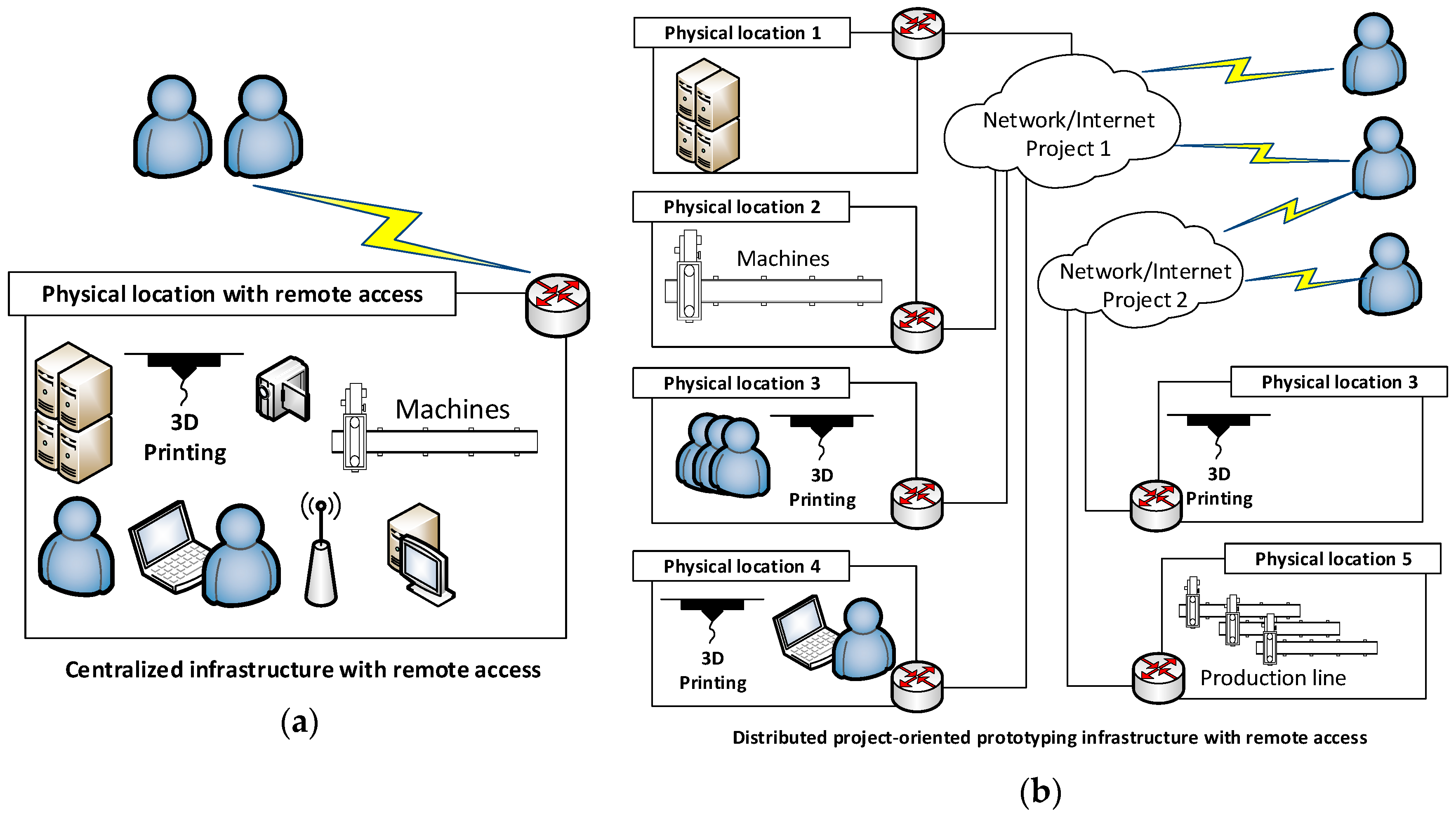
The classic approach to the design and construction of remote testing and manufacturing laboratories does not fit the modern approach to project creation and management. The designed nature of tasks, their geographic dispersion, and the multidisciplinarity of created projects and prototypes enforce flexibility at every stage of prototyping. For the implementation of specific projects, a team is formed and the necessary resources are obtained. This approach fits the agile project management methodologies used in Industry 4.0, but primarily agrees with the trends defined by Industry 5.0 [
17], which will increase the quality and efficiency of production thanks to artificial intelligence. However, this development is associated with a high security risk. Therefore, as part of Industry 5.0, it will be necessary to closely integrate people and machines in some decision-making areas. Differences in the approaches to prototyping are presented in
Figure 1.
Both architectures shown in
Figure 1 may be applicable. In both cases, the following problems can be identified in their implementation: difficulties with the standardization of solutions in the area of IT systems, different approaches to security policies, and different approaches to resource sharing. To further develop Remote Distributed Rapid Prototyping (RDRP) [
18] or Remote Rapid Prototyping (RRP), it is necessary to propose a functional, uniform and layered reference model. It is particularly important that RDRP or RRP systems at this stage be perceived as IT systems that must be constructed and designed. Thus, we propose a new design pattern, hereafter referred to as the framework.
The idea of remotely manufacturing components based on 3D printing is not a new concept. An approach based on the Tele-Manufacturing Facility (TMF) concept [
19] was proposed at the beginning of the 21st century. This approach enabled semi-automated remote design and 3D printing. Its basic assumption was to avoid errors by verifying and correcting STL (Stereolithography) files and then printing ready elements. A similar approach already applied on a global scale is the implementation of 3D printing services available for Windows 10 operating systems [
20]. Thanks to these services, even a complete amateur can become a designer of components that will later be printed on a local 3D printer (using LAN or WiFi links), or by ordering a print service from a remote location. In the first case, this service constitutes an improvement, but is limited from the perspective of the system’s scalability, as well as its lack of integration with other elements of the 3D printing process, e.g., a knowledge base or a system supporting the decision-making process of rapid prototyping. On the other hand, the approach in the second case is focused on the individual recipient and cannot be used today to provide professional or industrial solutions for distributed infrastructure. Combinations of both concepts include internet services such as i-materialise [
21], 3D Hubs [
22] and Igus [
23], which enable one to design and print 3D elements. Some of these services also include CNC (Computerized Numerical Control) machining and access to ready-made models. However, even these solutions provide only a limited range of services and also provide a closed environment without the possibility of integration with other distributed design and manufacturing resources. In this area, IT solutions supporting design processes could also be more widely considered. These issues have been described in various publications, which discuss, e.g., issues related to the combination of design processes, analyses using CAx (various Computer Aided systems) systems and elements of information algorithms used in incremental manufacturing processes [
24], and topological design and spatial analysis in the PLM (Product Lifecycle Management) area with selected applications of incremental generation systems [
25]. Several existing systems also support decision making in the process of rapid prototyping. Initially, these systems only included databases designed to facilitate the selection of an appropriate solution based on a catalog of available products [
19]. In the next period, knowledge databases appeared along with advanced mechanisms for choosing the right technology, e.g., 3D printing for current customer needs [
26]. However, all the solutions presented above do not introduce a comprehensive approach for the entire rapid prototyping process, taking into account both the design and manufacturing phases and combining ICT (Information and Communication Technologies), analytical, application, and control and measurement infrastructure with distributed software and hardware environments belonging to different entities. Notably, the problem of combining and standardizing the tools available on the market for the rapid prototyping (RP) process was already identified in 2002 [
19]. To date, research results and IT tools have been made available to enable the creation of geographically and functionally extensive prototyping systems.
To create systems that are optimal from a process and economic perspective, it is necessary to develop specific principles for the construction and integration of individual services and equipment. A new comprehensive approach for this process is proposed in the present paper as a coherent framework. In the literature, one can find examples of methods and other frameworks that are used in distributed manufacturing environments. However, these systems represent only a limited response to the aforementioned issue in the field of operational management, or refer to the implementation of a selected technology or tools supporting selected areas related to design and manufacturing. The framework proposed in [
27] only handles the desire to increase operational efficiency in an organization. For the framework described in [
28], the authors proposed a solution that aims to increase the efficiency of designing and reconfiguring multi-level and multi-dimensional manufacturing systems. The framework proposed in this paper cannot be compared to the Cloud-based manufacturing (CBM) architecture [
29], which facilitates decentralization, thereby increasing the use of design and manufacturing resources and reducing costs. The CMB model is an extension of web-based [
30] and agent-based [
31,
32] models. The former is based only on the classic client–server communication used on the internet, while the latter allows for more effective integration of independent resources in the form of agents. All three models can enable the remote design or manufacturing of components. However, they do not constitute a coherent environment that enables the integration of various design and manufacturing elements that were initially independent from each other. Moreover, the framework proposed in this paper can be implemented using cloud solutions. Nevertheless, this framework is not identical and depends on a solution to cloud computing.
Generally, the need to integrate production resources can be understood in terms of the ubiquitous manufacturing paradigm described in [
33,
34]. The assumptions of these models are based on the use of highly unified communication interfaces and rigid process rules, which must all be implemented at the same time so that a given entity can integrate with the production elements belonging to other entities. The use of this class of systems is possible for integrated producer groups, such as production consortia planning to create distributed production lines. The direct and widespread use of the above models in production environments is difficult and sometimes even impossible due to the high costs of their implementation. In contrast to these models, the present framework allows for the evolutionary implementation of successive levels of integration, while maintaining a high level of universalism and openness to the proprietary solutions of companies seeking integration with other entities.
This paper consists of several sections. The second section includes a description of the framework for the design of modern automated and computerized infrastructure. This section presents the main concept and the cross-layer structure of the layers. In section three, the level of IT maturity of the implemented framework is presented, as these levels facilitate the planning and implementation of the framework in terms of its organization and technology. The versatility of this concept allows its use in both homogeneous and heterogeneous environments in terms of ownership and location.
Section 4 covers the system architecture of the proposed framework along with the functionality of the individual modules, while
Section 5 illustrates the possibility of adopting the proposed architecture in a remote rapid prototyping environment.
Section 6 presents an example of the actual implementation of the framework proposed by the authors in cooperation with industry.
Section 7 compares the proposed approach with the classic approaches in terms of the actual production costs using three selected Fused Deposition Modeling (FDM) technologies. At the end, the results of the work are summarized, along with the plans for future work and the development of the proposed approach.
2. Proposed Framework
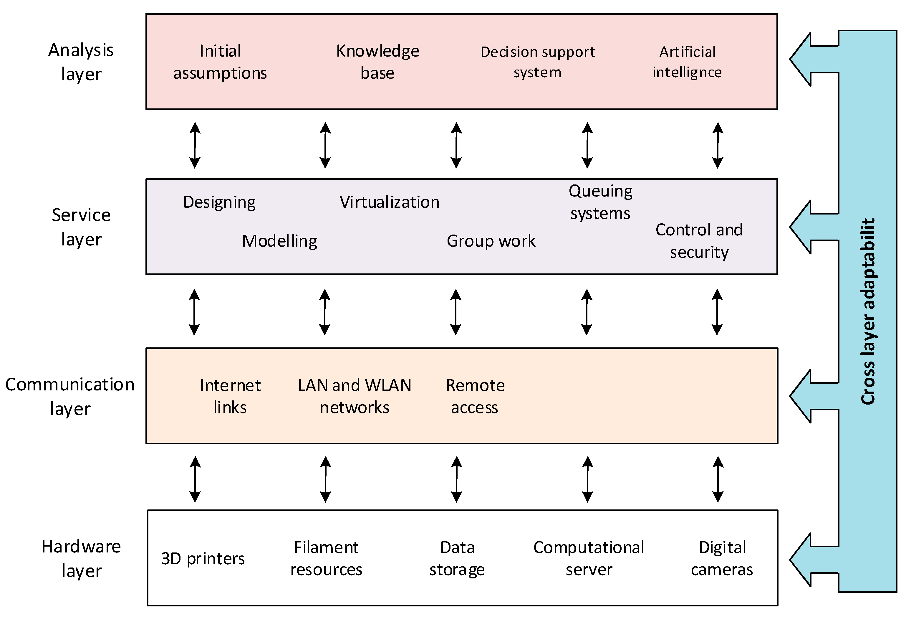
The large variety of technologies, application solutions, communication standards and architectures requires the development of an efficient structure that facilitates their management. The proposed structure divides the entire design area into layers, each of which is responsible for a different functional range (
Figure 2), while not introducing technological limitations. Previous models focused on individual elements of the design and manufacturing process [
27,
28,
29,
30,
33,
34]. Some of them [
33,
34] covered only the integration of the communication layer on the basis of selected mechanisms, standards and data transmission protocols. Others [
27] analyzed and implemented effective process management in the actual analysis/business layer. Other solutions involve architecture models related to the physical structure of the production system [
28]. However, a separate group of models consists of solutions related to processing mechanisms that are actually located in the service layer [
29,
30]. However, the proposed approach can consider several solutions while arranging their functional scope and implementing cross-layer mechanisms [
35,
36,
37]. Our experiences related to the construction of RP systems have shown that the process of building a laboratory for RDRP can be understood as building a specific IT system in which selected elements will be implemented using the batch processing paradigm. Such an approach entails the possibility of using a project approach based on the use of a framework that reduces the costs of system implementation and promotes the solution [
18]. The proposed framework (
Figure 2) has the characteristics of a universal solution, i.e., it can be defined in detail by both a single organization as well as by a cluster of organizations. In the initial phase, the framework project provides a set of guidelines for information systems that facilitate the construction of individual elements and the creation of communication interfaces. In the next stages, the framework may have already implemented elements of the software access and communication interface, as well as guidelines for the attached industrial elements.
The layers have been designed in such a way as to combine elements and actions similar to each other.
Hardware layer (w1): This layer includes the physical elements that make up the chain necessary for designing, modeling, manufacturing and control in the rapid prototyping process. Therefore, within this layer, one can distinguish the different production devices, specialized computing units, high resolution digital cameras and data storage necessary to collect the data used at particular stages of the prototyping process.
Communication layer (w2): This layer is responsible for providing a high-throughput communication environment that enables effective data exchange between all elements and persons involved in the rapid prototyping process. Thus, within this layer, the elements of the network infrastructure are separated, including the mechanisms for remote access.
Service layer (w3): This layer includes all activities and corresponding tools (primarily IT) used in most of the stages of rapid prototyping. On the one hand, these tools create a specific digital–virtual environment that enables the optimal use of available hardware platforms; on the other hand, these tools guarantee interoperability, group work, the ability to separate, and the integration of individual works.
Analysis layer (w4): This layer is the most important from the perspective of Industry 4.0 and the optimization of the rapid layer prototyping process. It mainly supports the functioning of the service layer, although it works with the hardware layer, as well as the communication layer (this will be described later in the paper as the cross-layer). This layer implements highly specialized tools based on artificial intelligence or knowledge, as well as systems supporting decisions based on fuzzy models. The proper use of this layer may increase the effectiveness of the manufacturing process, e.g., providing better management and selection of filament, better management of access to particular resources (manufacturing equipment, design applications and component modeling), and increase the quality of manufactured components.
The proposed framework has not only a sequential character (i.e., data from one layer are not only forwarded to the next one) but also a cross-layer feature. This property allows the exchange of information between layers (cross-interactions) that are not directly related to each other, so as to increase the efficiency of the entire infrastructure. Below are examples of cross-layer functioning in relation to the proposed framework:
Communication of the analysis layer with the hardware layer (with the participation of the communication layer) but omitting the service layer. The communication layer has a dual nature: it can be perceived as a passive computer network or as an active element shaping the RDRP system architecture. Whenever this layer is not explicitly mentioned, it should be treated as a functionally passive communication element. The direct cross-interaction of the analysis layer with the hardware layer is obvious. The hardware layer provides computing resources directly for programs at the analysis layer. Elements of manufacturing programs (e.g., for numerical machine tools) can be directly tested on machine controllers and images from cameras can be transferred directly to image recognition systems placed in the analysis layer. It thus becomes possible to carry out remote research, such as remote analysis of the distribution of machine operators’ focus areas, while working to optimize manufacturing procedures. Examples of such research carried out to increase the efficiency and safety of aircraft pilots are described in [
38]. However, similar studies could be carried out for operators of production machines, especially in an Industry 4.0 environment. Examples of interactions can be multiplied. An important feature of using cross-interactions is the possibility of partially implementing the framework in a given organization, or the possibility of system interactions within frameworks implemented in different clusters or organizations.
Communication of the analysis layer with the communication layer. This approach enables the collection of data based on physical and logical communication in the environment of programmable computer networks (e.g., Software-Defined Networking SDN) [
18,
39,
40] based on the data collected and the system’s knowledge of the communication environment, as well as the algorithms created for the optimal selection of parameters and communication paths. The system combines (automatically or with the administrator) the transmission environment with performance and logistics aspects.
Service layer communication with the hardware layer. In Internet of Things (IoT) devices, application modules collect and process telemetric data locally, e.g., the temperature, pressure, tool wear, etc. An example of such a service is hardware and manufacturing process diagnostics. The interactions of these layers are natural in the final stage of each iteration of the RDRP process during the production of the prototype.
3. Levels of IT Framework Maturity
The adopted model has a wider application than just the rapid prototyping process, as it is part of the whole idea of Industry 4.0. A separate issue is how to implement the framework in a given institution, cluster or company. The initial results of the research on and implementation of the test framework in real systems clearly show that full implementation of the entire model (even for newly-built systems) is difficult, and, in some cases, even impossible. This is mainly due to the time constraints of the project and the lack of a sufficient number of qualified specialists on the border of IT and industry. Therefore, the implementation of the proposed framework should adopt an evolutionary character. Due to the dominant nature of IT issues related to the construction of this class system, this criterion was selected for further analysis. To assess the level of implementation, the concept of the level of IT maturity of the implemented framework was introduced.
Definition 1. The level of IT information maturity of the framework is described by the variable p = {p1,p2,…,pn}. We describe the level of implementation of particular system features c = {c1,c2,…,cm} via the following matrix D of size n × m: This definition of levels of maturity allows a person to use his or her own set of key features for the planned implementation. Let us consider an example whose system features are defined as follows (
Table 1):
At the implementation stage, the system designers, in consultation with the business division, industrial partners, employees of the prototyping laboratory and customers, define a matrix with levels
D according to Definition 1. For the example considered, this matrix can take the following form:
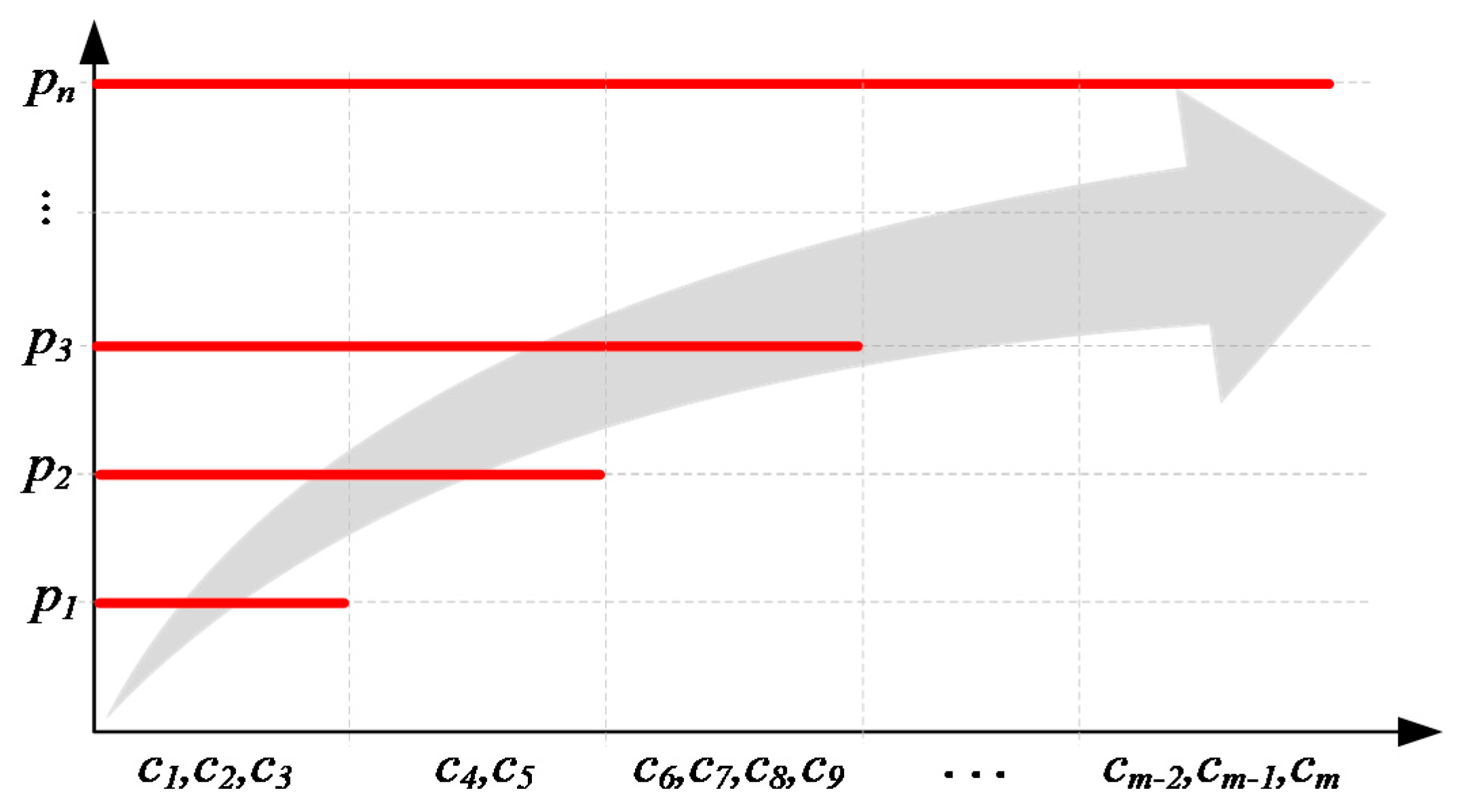
During the development of information systems supporting prototyping, the proposed framework can determine the features of the information system architecture required at each level of maturity. This allows one to plan the development of the system, but also determines the possibility of its integration with other systems. The levels of IT system maturity in relation to the development of a given system are presented in
Figure 3.
Of course, the proposed framework gives one the opportunity to create custom levels of maturity that correspond to the requirements of a given company, laboratory, or production cluster. To better illustrate the assumptions of the model, we proposed a general set of levels of maturity as the starting point for further work.
For the system characteristics given in
Table 2, the IT maturity level matrix will be as follows:
From the perspective of the matrix analysis, we should determine the correlation properties of the features that are appropriate for subsequent levels
. It is natural to include the following form,
, where
is a set of features specific to a given level
, where
. For example, from
Figure 3,
. However, one should consider a case where the level does not contain all the features of level
. In other words, if level
contains a set of features
, is it possible that the following situation may occur:
Admitting this situation will lead to the creation of a matrix with the following form:
With this approach, further levels of maturity will become less dependent on each other. Such a situation may apply to the implementation of some IT systems supporting the process of rapid prototyping and Industry 4.0. For example, consider a situation where one of the requirements of level is that an administrator allocates resources for given prototyping clusters (let us mark this attribute as ). Let us assume that one of the features of level is the introduction of automatic resource management systems using the SDN architecture. In this case, feature is unnecessary for level . For the example given, it is appropriate to use the inclusion described by Expression (1).
If the prototyping system or production system is built by one organization, ensuring the compliance of individual elements within one framework using a given matrix
D is a relatively simple task. However, if we consider the architecture presented in
Figure 1b, then it is necessary to ensure the compatibility of the maturity level in individual organizations for a given project being carried out.
4. System Architecture
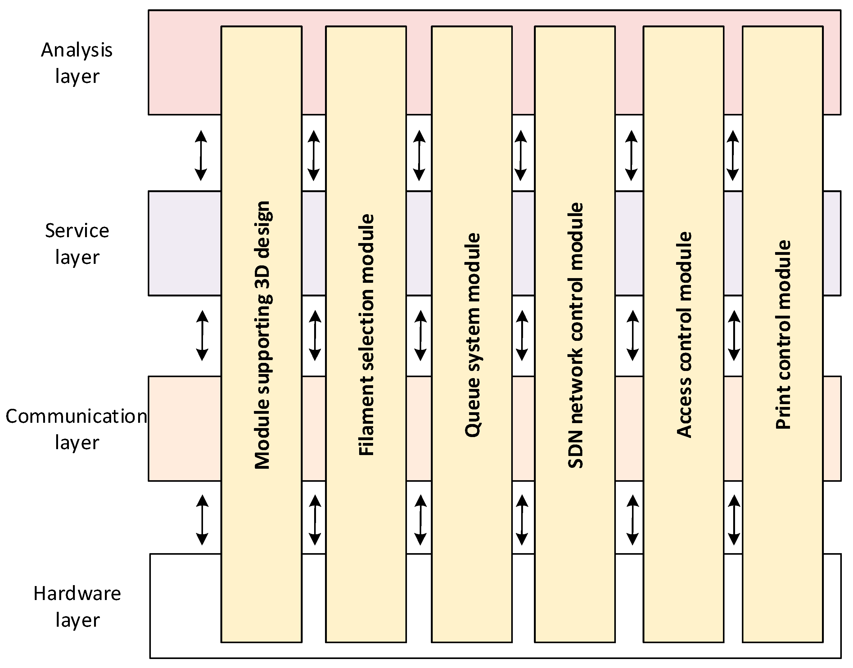
Considering the needs of the rapid prototyping laboratory, the following functional modules were defined to form an integrated system supporting the RP process:
3D design support module: A set of CAD tools limited to licenses and the performance of hardware infrastructure. To increase the flexibility of resource management, it is possible to use virtualization techniques and collective licenses.
Filament selection module: This module is based on the programmed mechanisms for selecting the correct production components according to the needs defined for the final product. The system includes a database of available filaments with certain technical parameters; a set of available 3D printers with their technical parameters linked to a set of available filaments that can be used on individual printers; a system for defining the technical parameters of the final element; and a previously established mechanism for selecting a filament for specific production tasks.
Queue management module: An IT system that manages planned tasks in the area of available resources (including filament for 3D printers). This system analyzes the available 3D printers on an ongoing basis in terms of their load, informing the person making orders about the planned start and end dates of the printout. This system considers the priorities of individual tasks. An extension of this module can also manage access to other resources, including CAD modeling tools.
SDN network control module: This module can optimize the use of ICT infrastructure resources, by implementing adaptive mechanisms for controlling access to network resources and flow control through the dynamic creation and modification of communication paths with appropriate Quality of Service (QoS) parameters. This issue is described in detail in [
18].
Access and control module (including remote control): A module responsible for access control to individual architectural resources of the rapid prototyping system. Two user groups can be distinguished here: administrators and operating users who are assigned the appropriate pre-defined access rights.
Print control and verification module: An IT system based on high resolution cameras. Data are then passed to the control system, which is placed in the analysis layer. There, the image from the camera is compared to the standard model, and then the level of the match is evaluated. When exceeding the pre-set limit parameters, the system may report the need to stop the manufacturing process.
These individual modules apparently belong to single layers of the framework presented earlier. However, in reality, these modules can (but do not have to) use the functionality of all four layers (
Figure 4). For example, the 3D design support module uses available hardware resources (including computing power) and access to this module can be done remotely through the communication infrastructure, thereby implementing the design and modeling service for the end-products and, at the same time, working under the initial assumptions and knowledge (the example model reference) from the analysis layer. Similar relations apply to the other modules.
5. Adopted Architecture for the Remote Rapid Prototyping Environment
The implementation of many research, development and didactic works brings together a team of specialists dispersed across various institutes, academic centers, startups, industrial laboratories, etc. Modern broadband networks and available IT solutions allow one to create a “virtual laboratory”, where scientists, engineers and students can carry out the entire rapid prototyping process from a place far from the real laboratory. The architecture of such a virtual–remote rapid prototyping laboratory (as part of the previously presented framework) is presented in
Figure 5.
The proposed solution is characterized by the following features:
Scalability: Assumptions regarding the architecture of the remote laboratory system do not introduce limitations in the number of users, 3D modeling platforms, available 3D printers, type of filament used, etc. Consequently, the system can be freely extended with new additional components.
Availability: Modern requirements for manufacturing systems, such as in a laboratory, can be available 24/7. Thanks to this, efficiency is significantly increased. This also represents a significant improvement for people who work from different time zones. Access is possible using both stationary and mobile devices.
Flexibility: The topology in which solutions of this class are created can combine any elements with each other. As an element of infrastructure, industrial resources, IT infrastructure and human resources are considered. Available IT tools allow the creation of many research scenarios without structural time or spatial constraints. The basic restrictions here are the cost of the task and the time of its implementation. During the creation of several projects implemented by industry partners in cooperation with the Rzeszów University of Technology, the key parameter affecting the time of implementation for a given laboratory was shown to be the standardization of communication interfaces and the use of generally known protocols and standards available on the market. This approach significantly increases the flexibility of the planned environment, and reduces the costs of its construction and operation.
Security: The system allows the application of modern methods for user verification and access control to individual elements of the entire system. This applies to both remote and local access. The main element is the RADIUS (Remote Authentication Dial In User Service) authentication server.
Universality: The adopted assumptions allow the interoperability of various solutions in the field of printing methods, applied object modeling techniques, authentication mechanisms, IT resource virtualization, etc.
Openness: The system allows the use of open solutions, including OpenSource and production solutions. This feature of the system was partially described in the previous section.
Verification/inspection: The verification and inspection of each prototyping process are crucial in order to verify the design prototype. In stages related to CAD design, object properties can be verified by numerical simulations, expert systems, etc. At the production stage, verification is carried out by a camera system and a machine operator whose working time can be shared among many projects. Operator and industrial work can also be supported by a dedicated IT system, e.g., related to anomaly detection or machining optimization.
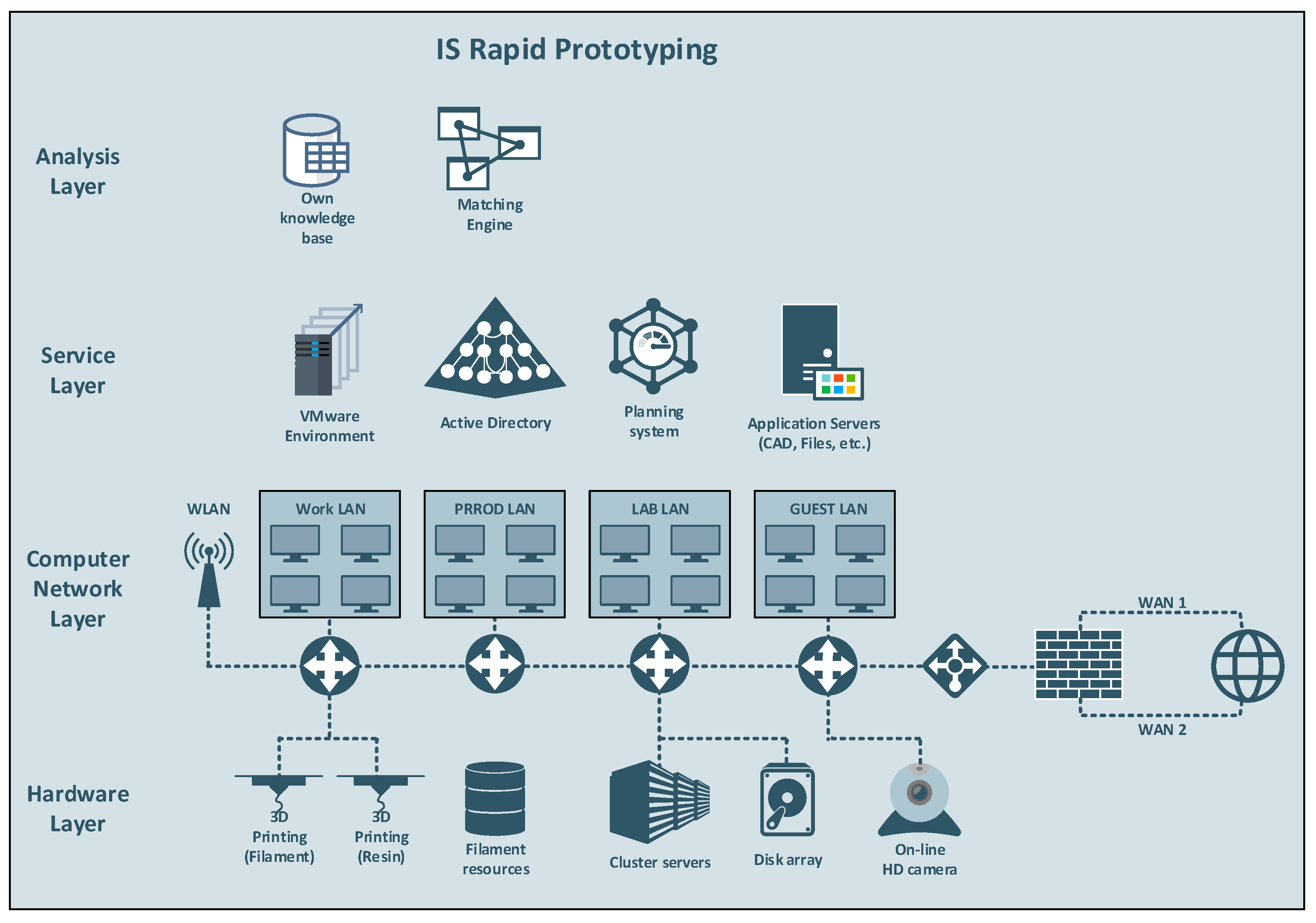
6. Implementation of the Framework in a Real Environment
The framework proposed in this paper was used for the creation and operation of a rapid prototyping environment designed at Rzeszow University of Technology. An example of such a solution is the iS Rapid at InfoSoftware Polska Ltd., Rzeszów, Poland. This system includes all four layers of the framework with the implementation of selected functionalities (
Figure 6). The system was implemented in the production process and offered remote access to the prototyping infrastructure. The entire system was built from scratch according to previously developed assumptions. Four levels of maturity were defined for the developed framework. At present, the system has reached the third level of maturity. Works related to the achievement of the fourth level of maturity are currently being finished. At the analysis layer, a knowledge base used by the engine to select the print parameters was implemented. The selection and configuration of the manufacturing process carried out in the analysis layer directly translates into the configuration of the virtual work environment created by the service layer. Of course, the user/client authentication process itself and remote access to appropriate resources must be carried out beforehand. Subsequently, the users have the ability to design their own components, using the available design and modeling tools, and can also import a unique ready-made object. All operations and processes are available through a so-called “thin client”, i.e., through a web browser. The user has the impression that he or she performs all activities locally on his or her computer/mobile device. One of the steps is the selection of the device and filament. This process is based on the predefined parameters of the previously designed prototype. On this basis, the system selects a set of recommended manufacturing devices and types of materials from which the given component will be finally made. Until final approval of the printout, the user can still go back and make any modifications. In one of the last steps, the user can determine the validity of his or her task, i.e., his or her priorities. This information will be used as input for the mechanisms that reserve IT and manufacturing resources.
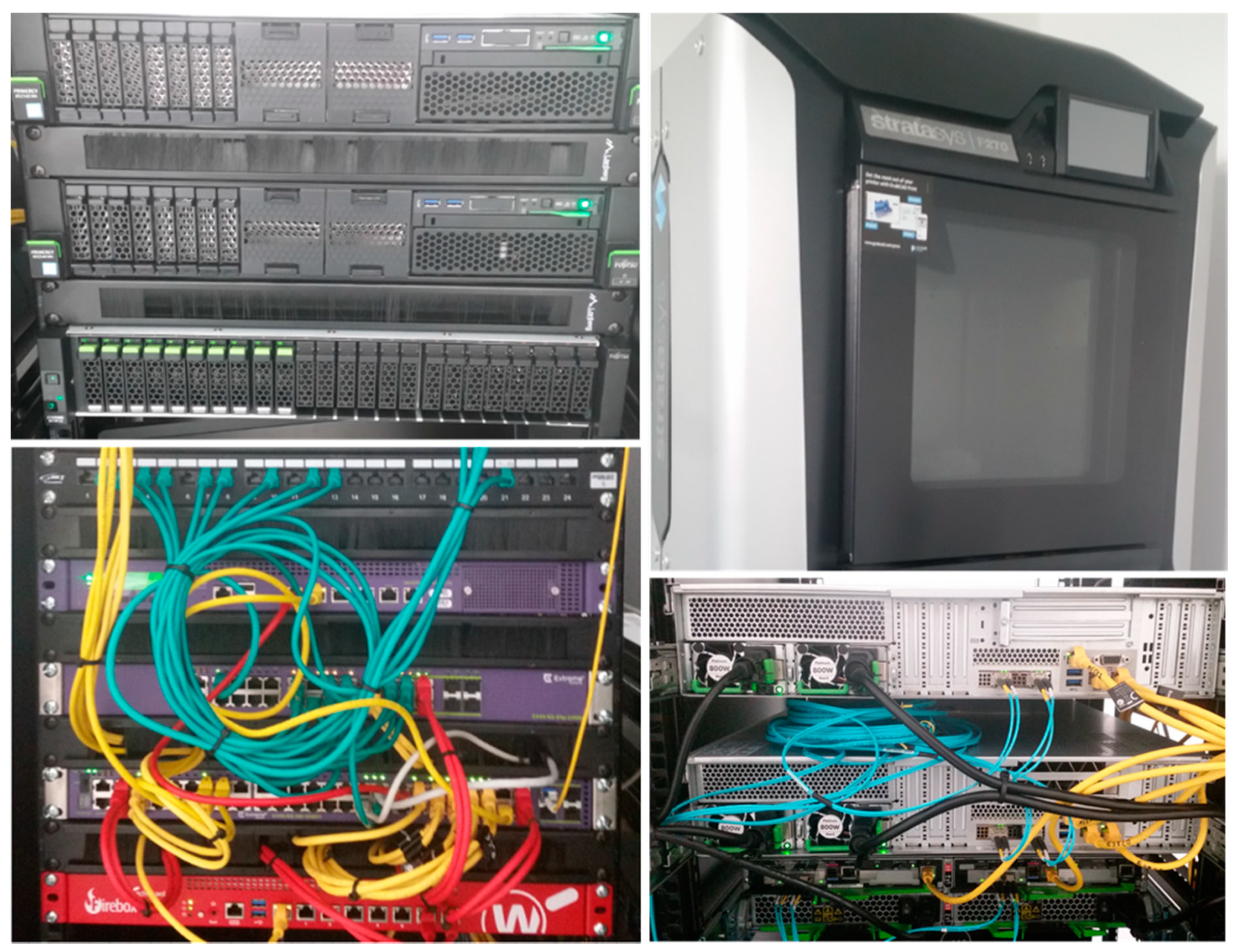
Resources (CAD system, operating system, network resources, disk resources, etc.) are allocated in a virtual environment at the time of a given user’s work and deleted after a session. The effects of the work are saved in the indicated place by the user, and can be used to implement the next stages of creating a prototype or develop another virtual work environment. The creation and the sharing of resources are carried out in the environment via automatically generated network connections implemented at the network layer (
Figure 7). At the network layer, there is also a remote access control system supported by NAC (Network Access Control) and Firewall systems, enabling access to resources through a dedicated application.
The connection system also provides access to hardware resources deployed in the hardware layer. The entire production process is controlled by the original queuing system, which is responsible for allocating resources from individual layers to specific users at a given time. The system is also responsible for the tariffication and can estimate the costs of physical prototype production as early as the stage of project creation.
At present, research work is in progress that will enable the transformation of the system from a centralized architecture to a distributed architecture. Cooperation has already been established with companies and external laboratories that offer other hardware components not available in the iS Rapid system. In the next stage, these components will be made available as a part of the iS Rapid system. The only condition for the implementation of such a structure is for the relevant partners to achieve the second level of maturity of the present framework. This will entail modifications in the area of the network and proper preparation of devices in the hardware layer.
7. Comparison between the Classic and Proposed Approaches
The introduction of a new approach, or rather a methodology, for rapid prototyping processes requires a comparison with extant or “classic” solutions. From the perspective of modern manufacturing, in addition to flexibility, reliability and availability, real production costs are also a very important issue. For classic manufacturing, most design and manufacturing infrastructure must be available to a given company or person. This approach involves the high purchasing costs of efficient workstations necessary for the modern creation of 3D models, specialized software, a suitable machine park (in the form of, e.g., 3D printers), having appropriate resources (e.g., various types of filaments), and a team of specialists to guarantee the high level of performance of the required components. For the purposes of this paper, we analyzed the infrastructures of three representative technologies, FDM (Stratasys), PJM—Polyjet Modeling (Stratasys) and SLS—Selective Laser Sintering (Sintratec), for which comparative analyses were also performed. As part of the study, the costs for achieving the organization’s readiness to implement the rapid prototyping process using the classic AM process were estimated using the resources at the Rzeszow University of Technology laboratory. A list of these costs is presented in
Table 3. These costs were selected based on a market analysis in Poland at the beginning of 2019.
Analysis of the data from
Table 3 allows us to estimate the costs of the so-called entry threshold: the costs primarily for the purchasing of software and materials as well as one employee (monthly salary). The employee is the operator of three 3D printers and software. For the rapid prototyping process laboratory, these costs are estimated at EUR 188,600. The above table presents the annual costs resulting from the depreciation of hardware and software, monthly costs and hourly averages, including costs related to the space and utilities used. Hourly costs can also be related to the operation of individual devices. The valuation of the implementation of a specific model must consider the specificity of the incremental technology used, the time of production using this technology, and fixed costs. The presented costs can be reduced by renting some of the elements on the market (including software), but in such a model, the integration of the entire manufacturing process is done on the client side.
In this process, considering the heterogeneity in the ownership of solutions used in single RP processes, there is a high probability that responsibility for prototyping failure will transfer between entities. For example, Company A producing a physical element may explain its faulty performance as a consequence of incorrectly selected parameters by the designer of company B, or improper processing by company C. In the proposed framework, transfers between companies A, B and C are implemented by strictly defined IT processes that ensure adequate quality, normalization, control compliance, and a number of other relevant parameters for a given case.
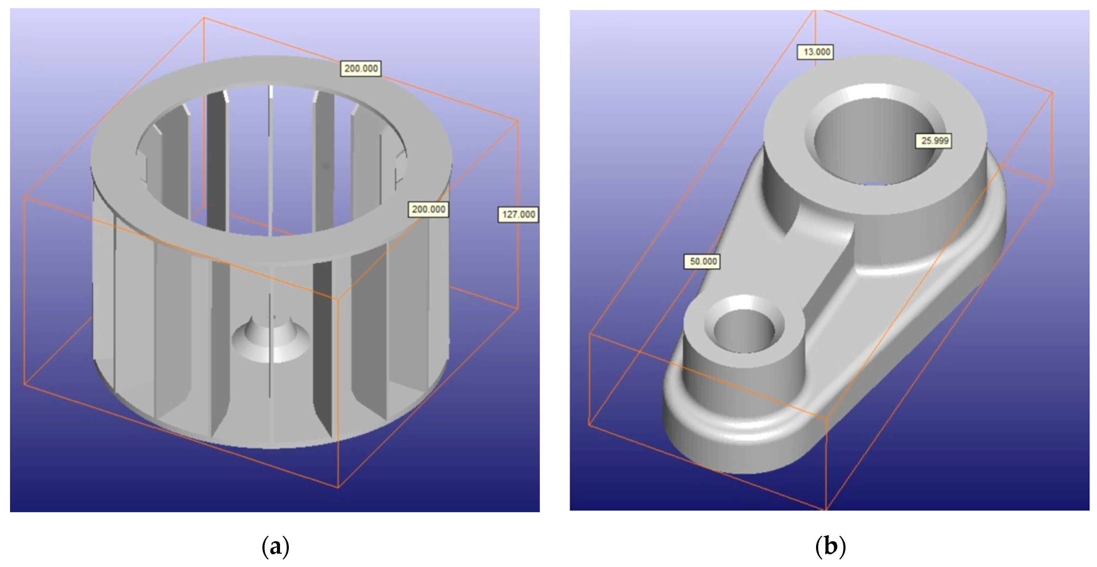
Next, the costs for the prototyping and production of two different (overall and structural) elements were analyzed: a rotor 200 m in diameter and 127 mm height (
Figure 8a), as a thin-walled element with a complex geometric structure, and a bracket (
Figure 8b), as a small element 50 mm long, 25 mm wide and 13 mm high, designed as a solid prototype.
In the cost assessment process, the printout of elements in three types of processes was analyzed:
Process 1 (M1): The company has its own infrastructure, production elements and qualified staff involved in the production of components. In this process, the costs related to the purchase and operation of equipment were also estimated. Estimating the manufacturing of an element in this model is the most difficult because it is necessary to consider the purchase and operation of equipment, and break down those values into the production costs of individual elements. Moreover, having our own machine park allows for the production of one type of element (with given parameters), and significantly reduces the prototyping process, which may require the use of various types of machines.
Process 2 (M2): In this model, with the exception of the designer, all elements used in the prototyping process are leased, including the CAD software. The entire operation is coordinated by the client and supported by a prototyping engineer.
Process 3 (M3): All prototyping is done remotely (along with the selection of the print parameters) using the system implemented by the company InfoSoftware using the proposed framework, which automatically coordinated and merged the production stages.
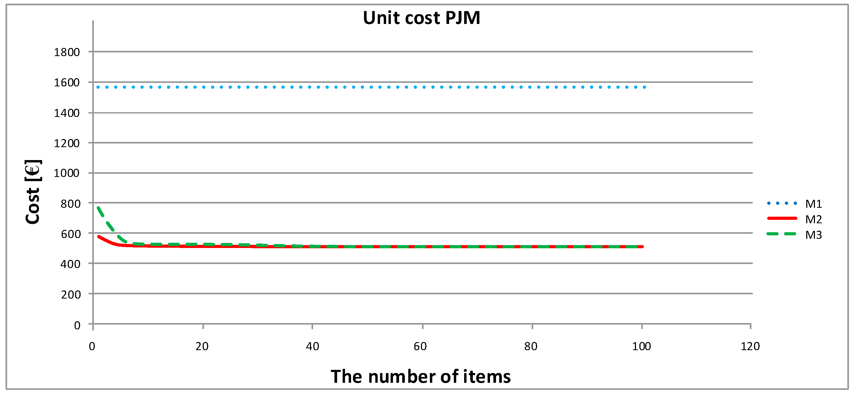
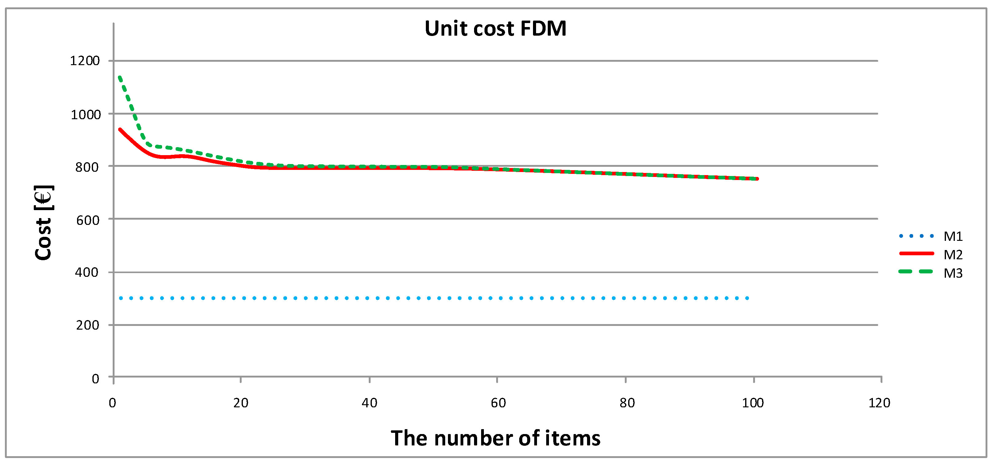
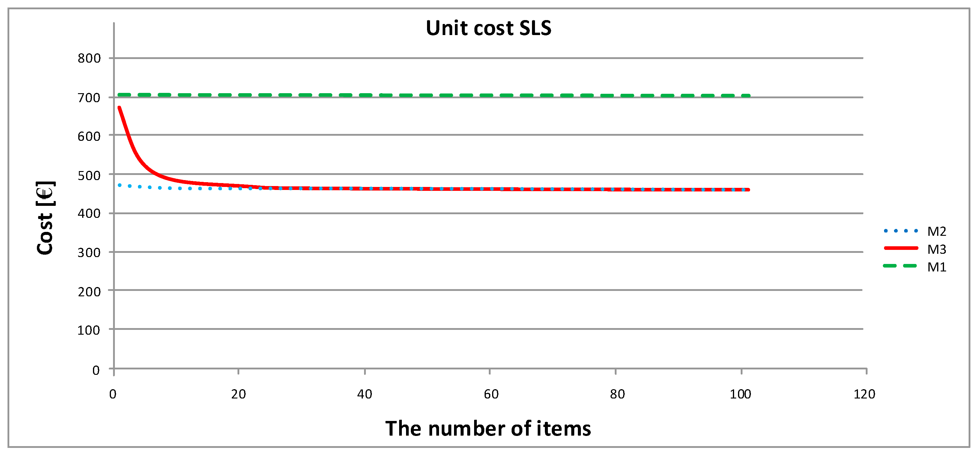
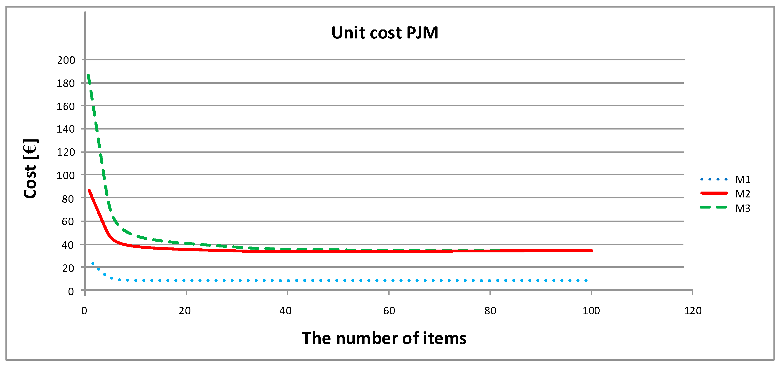
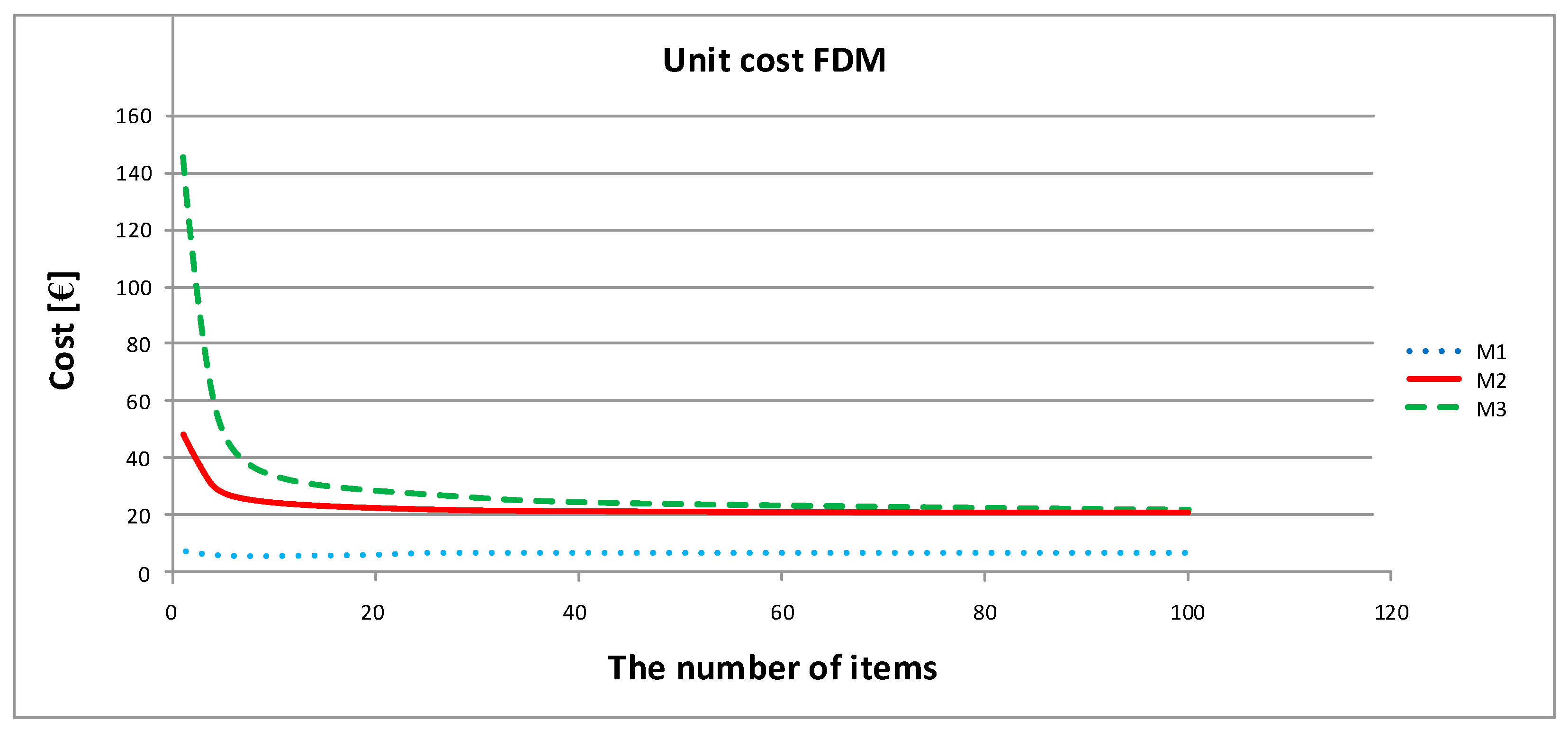
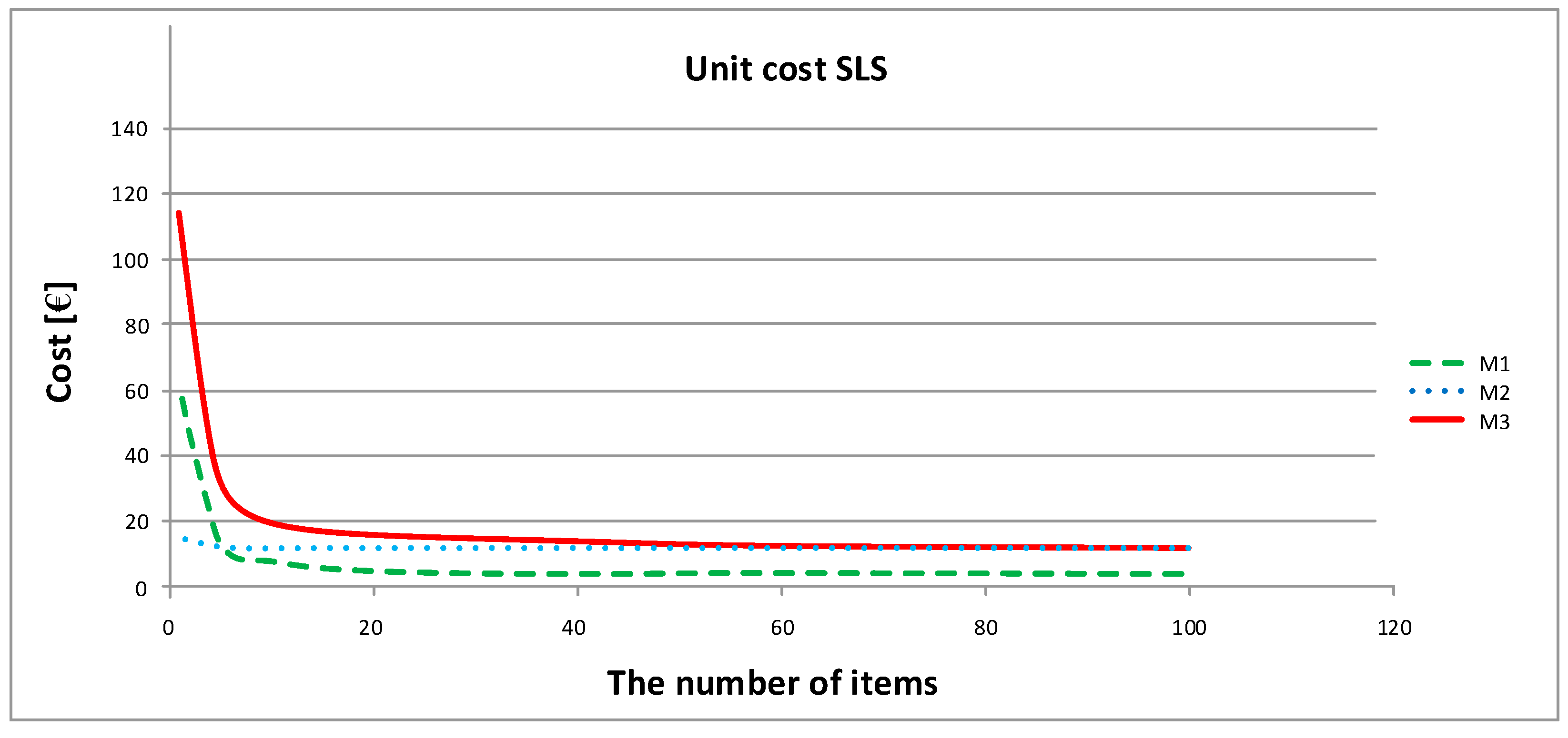
Determining the costs for the model was carried out in the first stage based on the resources and operating costs of the rapid prototyping laboratory of the Rzeszów University of Technology. A cost analysis was carried out for the production of prototypes using three industrial technologies: PJM, SLS and FDM. In addition, for process 1 and process 2, the costs were determined on the basis of quotes, cost estimates, or actual project and manufacturing works. The assumptions and controls for dimensional and shape accuracy were not considered because they are a separate issue. The list of costs is presented in
Figure 9,
Figure 10,
Figure 11,
Figure 12,
Figure 13 and
Figure 14. The cost of producing prototypes for a larger number of pieces was also analyzed.
The results of the simulations carried out for the two different prototypes and three process models, as well as three manufacturing technologies, show significant differences in all cases. The cost of making a prototype of one rotor is the highest using the PJM method and process 1 (M1), which thus involves the most expensive device, an important element of which is machine depreciation. In this case, the price is constant regardless of the number of pieces produced. Using processes 2 (M2) and 3 (M3), the price decreases when the number of pieces is increased to 10, and then stabilizes. The execution of the rotor model with FDM technology under process 1 also assumes a constant value. However, the cost is noticeably lower than that when using processes 2 and 3, for which the costs are also decreased by increasing the number of ordered items (manufacturing 20 pieces stabilizes the price). For SLS technology, the costs also stabilize around 20 pieces. The cost of making the rotor is the lowest for processes 2 and 3. This may be due to the applied technology, SLS, for which support structures are not required. For the prototype of the rotor with a complex spatial structure, the support structures for PJM and FDM technologies entail a significant cost connected with the use of supporting materials and the time necessary to develop supporting structures. For the majority of 3D printers of a medium size, it is possible to make a rotor with these dimensions as one piece in the machine’s working space. Hence, each rotor is made in a separate manufacturing process.
The costs for bracket manufacturing are different because brackets are a compact element with much smaller dimensions than a rotor. Due to the small size of a bracket, it is important to be able to make a few to a dozen pieces in one process. Thus, the most expensive context is the production of a single piece, which is especially notable for processes 2 and 3, for which cost stabilization occurs at 20 pieces of ordered product. For the model of process 1, the cost of execution is the smallest, and the course of the curve is gentle. For the prototype of the bracket, the highest cost was also observed for PJM technology with process 3. However, the difference between the production costs for individual technologies is not very significant in terms of the value itself, especially for over 20 pieces, compared to the rotor production price.
Analysis of the obtained results shows that the model based on the proposed framework M3 is extremely flexible, and is characterized by the low production costs of its prototype elements when the number of manufactured elements is greater than 15, which confirms the legitimacy of this model’s use in the production of around a dozen pieces. This model has also great advantages associated with its ability to select print parameters individually for each sample in a given series. Process 1, despite having the lowest production costs, is often characterized by the highest entry threshold cost in each of the technologies studied, which is associated with the purchase of equipment and the need to hire an employee to operate that equipment (
Table 3). However, for a large manufacturing company that intends to implement many prototypes incrementally for its own needs or for external orders, the long-term use of M1 is profitable.
8. Conclusions
This paper proposes a novel approach for the integration of the distributed additive manufacturing process enabling remote designing, the selection of appropriate manufacturing means, and the implementation of a physical production process and control at all stages. This approach was possible thanks to the development of an unprecedented framework, through which we were able to integrate distributed and functionally different elements (IT and manufacturing), forming a coherent design and manufacturing system. Importantly, this framework ensures not only an increase in production efficiency but also shortens production time, reduces costs, and increases the flexibility of and accessibility to the latest methods and design and manufacturing tools. In addition, we presented a mechanism that facilitates the integration of independent manufacturing environments by considering and implementing appropriate levels of maturity in the system. The validity of the presented solution was also confirmed by its implementation in a real production environment, i.e., at Infosoftware Poland. At present, work is in progress to integrate the rapid prototyping laboratory of the Rzeszów University of Technology with the infrastructure of the company to expand the available functionality, i.e., by providing a larger machine park, a wider range of design and modeling tools, and facilitating the development of analytical tools supporting the decision-making process. The presented platform can be widely used in the automotive and aerospace industries, and will facilitate cooperation between industrial clusters and academic centers to a higher degree, as well as encourage cooperation between small enterprises and startups. From the perspective of management, the technical implementation of the presented framework allows one to adapt to the needs of globalization, and facilitates the integration of distributed resources. Thus, this framework affects business, logistics and technological processes. One of the implications of implementing such a framework is the need to develop or adapt existing workflows to the new heterogeneous and distributed work environment. This is an interesting issue and may constitute the background of a new article. Considering the technological aspects, it remains a large challenge to achieve higher levels of maturity in a diverse ownership environment. This process requires cooperation and adoption at the management levels regarding the common assumptions behind the direction of development and implemented investments. In a homogeneous ownership environment, the related processes and decisions are much simpler. One of the significant limitations, that may affect the speed and scope of the integration of distributed heterogeneous design and production environments, is the lack of protocols and standards enabling the use of plug-and-play techniques known from ICT environments to enable the automated integration of physical devices with design applications and the preparation of the final manufacturing process, as well as with job queuing and decision support systems. The current approach based on the individual integration of individual infrastructure components requires a great deal of time and effort to achieve a higher level of maturity. The potential development of technology in this area could contribute to the full use of cross-layer optimization, as well as full automation of the attachment and disconnection of individual production devices. Of course, manufacturers of production devices use selected communication standards with their own dedicated applications, but there is currently no uniform mechanism comparable to the automatic installation of drivers in computer devices. Development in this direction would not only concern technological development, but would also influence the evolution of management models. The proposed solution, especially in terms of achieving the highest level of IT maturity, may enable the further evolution of productions methods toward Industry 5.0. Such progress will entail the implementation of fully autonomous production areas, where, after ensuring integration at the ICT level (i.e., IoT), it will be possible to implement a concept based on self-adaptive IoE (Internet of Everything) systems. Under this approach, IT systems based on artificial intelligence, machine learning, Big Data, and modern and safe communication systems will not only support decision-making processes at various stages of design and manufacturing, but will gradually replace them by creating Integrated Adaptive Generation Systems. In future works, we plan to develop solutions supporting decision-making in the field of design and production based on the experience of engineers, available technological databases and expert systems in the form of an iterative adaptive decision support system improved via the loopback model for Cyber–Human systems. Such a system would shorten the time needed for the design and production process, reduce the costs related to corrections and waste, and thus increase the quality of the services provided.

 ,
, 


