Position Deviation Control of Drilling Machine Using a Nonlinear Adaptive Backstepping Controller Based on a Disturbance Observer


1
School of Mechatronic Engineering, China University of Mining and Technology, Xuzhou 221116, China
2
Jiangsu Collaborative Innovation Center of Intelligent Mining Equipment, China University of Mining and Technology, Xuzhou 221116, China
3
School of Mechanical & Electrical Engineering, Henan University of Technology, Zhengzhou 450001, China
*
Author to whom correspondence should be addressed.
Processes 2021, 9(2), 237; https://0-doi-org.brum.beds.ac.uk/10.3390/pr9020237
Submission received: 29 December 2020
/
Revised: 23 January 2021
/
Accepted: 24 January 2021
/
Published: 27 January 2021
(This article belongs to the Special Issue Advances in Condition Monitoring, Optimization and Control for Complex Industrial Processes)
Abstract
:Thin coal seam mining is a development direction to solve the problem of energy supply at this stage, which cannot be realized by small working space, low automation, and drilling deviation. In this paper, a nonlinear adaptive backstepping controller based on a disturbance observer is proposed and used on a coal auger for position tracking control to achieve directional drilling. Firstly, a nonlinear dynamic model for the deflection control mechanism is built with the consideration of parameter uncertainties and external disturbances. Then, the parameter uncertainty and external disturbance are regarded as a system compound disturbance. Furthermore, a disturbance observer is designed to estimate the system compound disturbance and a nonlinear adaptive backstepping controller was proposed to compensate the system compound disturbance. The upper bound of the compound disturbance, which can effectively reduce the chattering in the directional control process, cannot be obtained easily. A stability analysis of the DCM (deviation control mechanism) with the proposed controller is proved based on the Lyapunov theory. Finally, an electro-hydraulic servo displacement control experimental system with matlab xPC target rapid prototyping technology and a prototype experiment system is established to verify the effectiveness of the proposed control strategy. The experimental results indicate that the proposed controller can yield more satisfactory position tracking performance, such as parameter uncertainties and external disturbances, than the conventional proportion integral derivative (PID) controller and an adaptive backstepping controller. Using the control strategy, technical breakthrough on horizontal directional drilling can be realized for thin coal seam mining.
1. Introduction
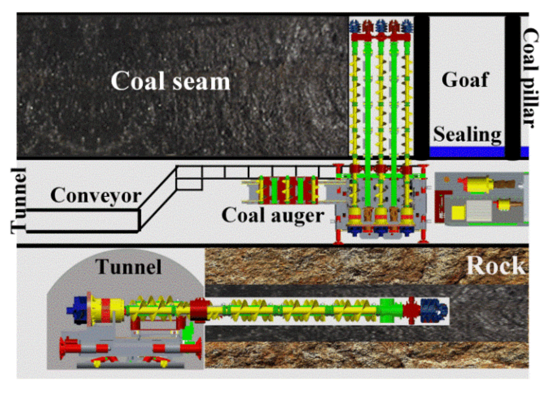
Thin coal seams, which are indispensable coal resources, are widely distributed around the world. The question of how to exploit these coal seams with high efficiency and mechanization has become the main development direction of coal excavation. The coal auger is a new type of thin seam mining equipment that has extensive prospects thanks to its characteristics of unmanned and non-supported coal face mining. Recently, a new type of coal auger working mechanism with five bits was used for further improving coal mining efficiency [1,2]. The drilling technology is shown in Figure 1. However, owing to the constraint reaction force of the coal wall, gravity, cutting resistance, and friction, the vibration of the working mechanism is relatively excessive, which may cause serious drilling deflection [3]. As a result, the efficiency of drilling and excavating is unbalanced. However, the excavation process has realized intelligent and rapid driving, based on supporting design optimization [4,5] and intelligent control [6].
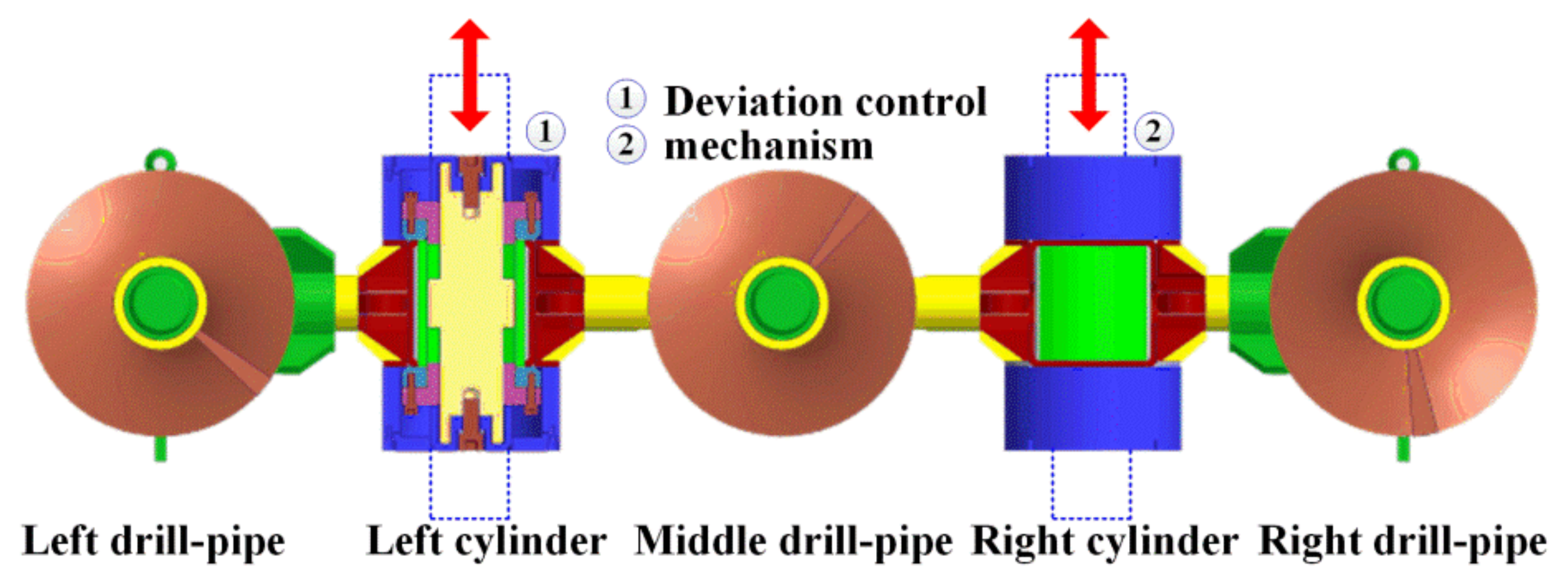
The dynamic characteristics and stability of the drilling mechanism are the main factors leading to deviation. There are many kinds of vibration forms—including vertical vibration [7], lateral vibration [8], torsional vibration [9], and coupling vibration [10]—in the actual drilling process that lead to deviation. For different structures of drilling mechanism, scholars have carried out extensive research on vibration characteristics to obtain the deviation behavior due to vibration [11,12,13,14]. However, the deflection in long-distance drilling cannot be solved by restraining the vibration behavior. Therefore, direct deflection detection and control methods have been extensively studied. Lueke et al. [15] analyzed the influence of borehole diameter, drill pipe pressure, bit structure, drilling depth, and geological conditions on deviation fluctuation in the process of directional drilling. It was pointed out that a deviation prevention device with a reasonable arrangement could realize deviation control in drilling. Manacorda G. [16] designed and put forward a kind of ground-penetrating radar equipment for a horizontal directional drilling (HDD) bit by using an angular displacement sensor and communication module. The equipment can provide the real-time position and pose information of the bit and provide a reference for controlling the drilling direction. Inyang I.J. [17] proposed a bilinear model attitude control method for directional drilling tools that describes the non-linear characteristics of directional drilling tools more accurately than the existing linear models are able to. Thus, by expanding the performance range, the attitude control of directional drilling tools was more effective, robust, and stable, which significantly reduced the effect of measurement delay and interference on the stability and performance. Kim J. [18] proposed a new hybrid rotary steering system aimed at the problem of uncontrollable borehole curvature in long-distance directional drilling. This system combines a traditional drill bit with a push bit and adopts a hybrid structure involving a hydraulic cylinder and spherical joint to achieve better maneuverability. Comprehensive analysis shows that deviation control in directional drilling was achieved by designing a special bit. Therefore, in view of the unique structure of the coal auger, a new hydraulic deviation correction mechanism was designed to achieve directional drilling. A structure diagram of the deviation control mechanism is shown in Figure 2.
The DCM (deviation control mechanism) can be regarded as an electro-hydraulic servo control system. The position control of the DCM can be partially realized using a conventional proportional-integral (PI) controller [19] and backstepping controller [20]. However, the DCM is a complex nonlinear system with parameter uncertainties, such as servo-valve and hydraulic actuator dynamics [21], stiffness and damping differences [22], and external disturbances such as friction between the rod and bore of hydraulic cylinders [23]. All these factors make it difficult to obtain satisfactory position coordination performance with the conventional PI controller and backstepping controller, because these two controllers cannot adjust their control parameters in consideration of the parameter uncertainties and external disturbances of the DCM. In order to reduce the effects of the above-mentioned parameter uncertainties and external disturbances of the DCM, many control approaches, including adaptive sliding mode control [24], adaptive backstepping control [25], and a nonlinear disturbance observer (NDO) [26], were introduced. A nonlinear adaptive backstepping controller was employed to improve the position tracking performance, estimating uncertain parameters through adaptive laws derived by guaranteeing the stability of the DCM [27,27]. Choux M. et al. [28] developed an adaptive backstepping controller for a nonlinear hydraulic-mechanical system that handled uncertain parameters related to the internal leakage, friction, orifice equation, and oil characteristics. A new smooth and continuous sliding mode control law was proposed to solve the design conflicts between sliding mode control technology and backstepping adaptive control technology for position control by Ji X.H. [29]. An improved noise-alleviation method was proposed by Yang G.C. [30,31] to achieve the high-accuracy calculation of the standard sign function in direct adaptive control for high-precision position control. Zheng J.Z. [32] concerned a high-accuracy tracking control for hydraulic actuators with unmodeled flexible dynamics considering the structural flexibility of the mechanical components. However, external disturbances that usually exist in nonlinear systems are not taken into account during the controllers’ design process. Guo K. [33,34] presented a nonlinear cascade controller based on an extended disturbance observer to track the desired position trajectory for electro-hydraulic single-rod actuators in the presence of both external disturbances and parameter uncertainties. Kasac J. [35] proposed a robust output tracking controller using external disturbances observer for reducing the measurement parameters of the control system. Hu X. [36] designed a dynamically positioned vessel exposed to unknown time-varying external disturbances, incorporating fuzzy logic systems (FLSs), projection operators, and the “robustifying” term into the vectorial backstepping technique. Teoh J.N. [37] took into consideration the rejection of narrow-band disturbances at two frequencies higher than the servo bandwidth in order to obtain a good positioning accuracy for a micro-actuator. A phase-stabilized feedback controller combined with a disturbance observer structure was applied to achieve the rejection of the two disturbances.
However, most of the research focuses on control accuracy using high-precision control elements. Our study tries to combine and improve these proposed controllers and use a control element with a slightly lower accuracy by achieving the required positioning control for easier industrial application. The main contribution of this work is to design a combined controller that consists of a nonlinear adaptive backstepping controller (NABC) and a disturbance observer (DO) for DCM and its implementation in a double-rope winding hoisting experimental system. The basic concept of ABSMC-DO is to regard the parameter uncertainty and external disturbance as a system compound disturbance. A disturbance observer was designed to estimate the system compound disturbance. A nonlinear adaptive backstepping controller was proposed to compensate for the system compound disturbance. The proposed control system does not need to accurately obtain the external disturbance, and has a good control effect for parameter uncertainty and uncertain nonlinearity. A stability analysis of the DCM with the proposed controller is performed based on the Lyapunov function. A series of experimental tests are carried out on the electro-hydraulic position control system with the characteristics of large load inertia and large external interference and a prototype to verify the availability of the proposed controller. Using the novel control method, the upper bound of the compound disturbance, which can effectively reduce the chattering in the directional control process, cannot be obtained easily.
2. Dynamic Model of the DCM
The structure of a servo valve-controlled hydraulic cylinder was adopted as the deviation control mechanism (DCM). The dynamic model of the DCM is shown in Figure 3. It is comprised of a double-rod cylinder, a 3–4-way servo valve, and a load force. The goal is to position track any specified motion trajectory as closely as possible. The nonlinear dynamical model of the DCM is given as follows [38].
We defined the right shift of servo valve spool as positive. In this direction, the load flow QL of the servo-vale is defined as follows:
where Cd is the flow coefficient of the servo valve, is the area gradient of the servo valve, is the spool displacement of the servo valve, is the differential pressure between the two chambers of the electro-hydraulic cylinder, , is the supplied system oil pressure, is the hydraulic oil density, and sgn is a symbolic function that is defined as follows:
As the dynamic response frequency of the servo valve is far higher than that of the correcting cylinder, without considering the dynamic model of the servo valve, the control accuracy of the system is less affected. The displacement of the servo valve spool and the control voltage can be regarded as a linear proportional relationship. Therefore, the approximation can be expressed as follows:
where kxv is a positive constant and u is the control voltage.
Considering the equivalent load elastic deformation during drilling, applying Newton’s kinematics law, the force balance equation of the deflection control cylinder can be obtained:
where is the total mass, is the viscous damping coefficient, is the spool displacement of the deflection control cylinder, is the equivalent elastic stiffness coefficient of the drilling load, and is the external load force acting on the control cylinder.
Considering the internal and external leakage of the deflection control cylinder, the load flow in two chambers of the deflection control cylinder is established as follows by applying the flow continuity equation:
where is the flow rate (m3/s) in intake chamber 1; is the flow rate in the return chamber 2; is the internal leakage coefficient of the deflection control cylinder; is the external leakage coefficient of the deflection control cylinder; is the effective bulk modulus; and are the initial volume of the oil-in cavity and oil-out cavity, respectively; and and are the oil pressures of the oil-in cavity and oil-out cavity, respectively.
Assuming that the cylinder initially stays in the middle position, . Vt is the total volume of the oil-in cavity and oil-out cavity. Because , it can be neglected. The load flow is defined as the average flow of the oil-in cavity and oil-out cavity as follows:
where is the total leakage coefficient and can be written as .
The displacement signal of the servo valve spool is used as the control input. Based on the derivation and discussion of the equations, the displacement, velocity, and acceleration of the deflection control hydraulic cylinder can be obtained. As the leakage coefficient and bulk modulus change with varying time and the external load of the drilling mechanism cannot be accurately obtained, the directional control system can be regarded as a strong nonlinear system with parameter uncertainty and disturbance uncertainty.
A state space equation was used for improving the control accuracy of the DCM based on the proposed dynamic model. State variables can be defined by . The directional control system can be presented in a state space form as follows:
where , , , , , .
The control system includes not only the nonlinearity of the hydraulic system, but also uncertain external disturbances, such as the friction force in the drilling process, the friction between the control cylinder and the piston rod, and the cutting load. The model uncertainty and external disturbances are regarded as a compound disturbance term, so the new system state space equation can be expressed as follows:
where is the compound disturbance term of the deflection control system.
3. Controller Design
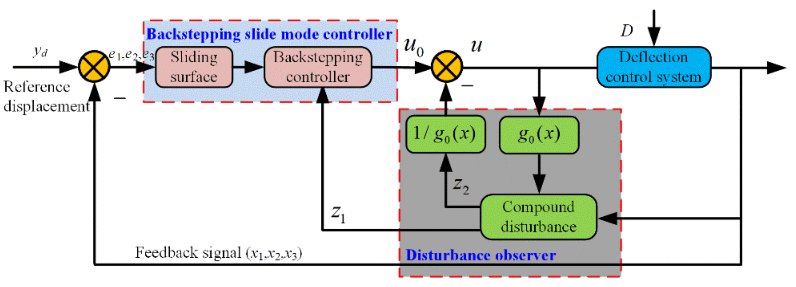
Position control systems based on the adaptive control method have been widely studied. However, it is difficult to obtain the optimal value of the compensation parameters when the external parameters change too much. A novel control method combining adaptive backstepping sliding mode control and an extended state observer was proposed to solve the above problems. The framework of the nonlinear adaptive backstepping control based on the disturbance observer (ABSMC-DO) for the DCM is shown in Figure 4. The basic concept of ABSMC-DO is to regard the parameter uncertainty and external disturbance as a system compound disturbance. A disturbance observer was designed to estimate the system compound disturbance. A nonlinear adaptive backstepping controller was proposed to compensate for the system compound disturbance. The stability of the overall system with the proposed control algorithm can be proved using Lyapunov analysis. The upper bound of directional vibration can be obtained without any disturbance. Using ABSMC-DO, the upper bound of the compound disturbance, which can effectively reduce the chattering in the directional control process, cannot be obtained easily.
3.1. Adaptive Backstepping Slide Mode Controller
The target of this part is to obtain the value of control input QL to track the reference displacement with an adaptive backstepping controller. The controller design process can be divided into the following four steps.
Step 1: Define the displacement tracking error e1 and the intermediate dummy variables of the system intermediate dummy variables as follows:
where yd is the displacement reference value of the deviation control cylinder and a1 and a2 are intermediate dummy variables.
Step 2: Design the virtual control variable a1 as follows:
where .
To ensure the displacement tracking error e1 tends to zero, a semi-definite Lyapunov function can be defined as follows:
The time derivative of V1 can be given as follows considering Equation (11):
Step 3: To ensure the system is stable and convergent, . Therefore, a new Lyapunov function for e2 is defined as follows:
By deriving Equation (14), we can obtained the following:
Then, the virtual control variable a2 can be designed as follows:
where .
is calculated as follows:
Step 4: To ensure the Lyapunov function defined above has positive semi-definite properties, the synovial switching function is designed to make the system error converge to the synovial surface gradually as follows:
where c1 > 0, c2 > 0, and satisfied Hurwitz polynomials .
The exponential reaching rate is employed in this work to make the control system approach a sliding surface:
where is an exponential reaching term and parameters and k3 are both positive.
The larger the parameters and k3, the faster the convergence. However, too large parameters will cause system chattering and even lead to system instability.
Further, by deriving Equation (18), the following can be deduced:
The compound disturbance term in Equation (20) includes both parameter uncertainty and external disturbance. Therefore, the system controller is designed as follows:
As is a variable related to the parameters of the deflection-control hydraulic cylinder, the denominator of the designed controller (21) is not zero, which ensures its non-singularity. However, the unknown disturbance D in the controller directly affects the output performance and shaking characteristic. A disturbance observer was built to estimate and compensate the unknown disturbance D to avoid the control error and shaking.
3.2. Disturbance Observer
The compound disturbance is expanded based on the control principle of the extended state observer, so that the sliding surface in Equation (20) can be re-expressed as follows:
An extended state observer is designed for Equation (20) with a second-order form:
where z1 and z2 are the observer outputs, e1 is the estimate error for the observer, and parameters and are greater than zero.
Function is defined as follows:
where 0 < a < 1 and δ > 0.
Remark 1.
For the second-order extended state observer of Equation (23), there are appropriate design parameters β1, β2, a, and δ that make the observer steady.
Furthermore, the observer estimation error equation is established as follows:
The estimation error of the observer in steady state can be expressed as folows:
According to Equations (24) and (26), the estimated error of the observer can be processed as follows:
Considering Equation (24), the observational errors can be divided into two cases:
Combined with Equations (27) and (28), it can be seen that reasonable values for parameters β1, β2, a, and δ determine the observer estimation error. Therefore, as long as the appropriate parameter values are selected, the state estimation error can be sufficiently small, so the observer output can converge to a certain critical region of s and D, which guarantees the observation accuracy of the compound disturbance.
3.3. Stability Analysis
The compound disturbance D can be replaced by the proposed extended state observer. Thus, the control law from Equation (21) can be rebuilt as follows:
Remark 2.
For the directional control system of Equation (8) with parameter uncertainties and external disturbances, the extended state observer of Equation (23) is used to estimate the compound disturbance D. If there are suitable parameters, β1, β2, a, and δ, the control system output will gradually tend to the sliding surface and keep a relative slip on the sliding surface, so that the position output of the system can accurately track the desired trajectory. The parameters must meet the following conditions:
Proof .
Define the Lyapunov function:
Combining Equations (13), (18) and (29), Equation (31) can be derived as follows:
where and
The designed parameters k1, k2, k3, c1, and c2 are all greater than 0 and constants, which can ensure that the first- and second-order principal minor determinants of matrix Q are positive. The fact that the third-order principal minor determinant of matrix Q is positive can be guaranteed by Equation (30). Therefore, matrix Q satisfies the positive definite.
From Equation (33), the following can be concluded:
where is the minimum eigenvalue of matrix Q.
The tracking errors converge to a neighborhood of zero by assigning reasonable values for parameters β1, β2, a, and δ. Therefore, design parameter k3 satisfies . Based on Equation (29), when , the system will embody asymptotic stability.
Define . When , . The integral result is expressed as follows:
According to the boundedness of and , it can be deduced that . Therefore, when and . Then, the sliding function s would be closer to zero, . □
Based on the Lyapunov stability criterion, the system will gradually approach the sliding surface and eventually converge to the sliding surface. Therefore, the output of the directional control system can effectively track the desired trajectory.
4. Experimental Research
4.1. Experimental Introduction
Figure 5 depicts an electro-hydraulic servo displacement control experimental system that is utilized to implement the proposed nonlinear adaptive backstepping control based on the disturbance observer (ABSMC-DO) designed in this paper and experiment on the deflection control testing system. The testing system is composed of a loading system and an actuating system. The loading hydraulic cylinder and actuating hydraulic cylinder are the actuators and are driven by the proportional servo valve (MA-DLHZO-TES-PS-040) manufactured by the YWL VTOZ company. The MTS magnetostrictive displacement sensor (RPS0500MD601V810050) with an accuracy of 0.1 mm is used to measure the hydraulic cylinder position. For measuring the pressure changes in real time, two pressure sensors (Mik-p300 and 0–20 Mpa, resolution ±0.5%) are installed on the oil inlet and outlet of the loading cylinder and actuating cylinder. All the executive elements and acquisition elements have relative control precision to realize industrial application. Different external loading signals, such as waves and sinusoidal steps, are imposed to the actuating cylinder. A tension pressure sensor is employed to measure the external loading with a repetitive accuracy of 0.05% FS (Full Scales).
The signals of each sensor are collected in the industrial computer through an analog to digital (A/D) board, PCI-1723. The 16-bit A/D board transforms the feedback analog signals measured by the sensors to digital signals and then sends the acquired digital signals to the controller after converting in signal modular. Using the RTX module of the industrial computer, the proposed control algorithm is programmed in Matlab/Simulink and then compiled and downloaded to the matlab xPC target real-time controller. The real-time analog control output signals that are produced by the 12-bit D/A board PCI-6126 and processed by the signal modular are sent to the two servo-valves to control the two electro-hydraulic cylinders.
To verify the effectiveness of the proposed control strategy for the DCM, experiments were carried out on the electro-hydraulic servo displacement control experimental system using the conventional proportion integral derivative (PID) controller, the adaptive backstepping controller (ABC), and the proposed ABSMC-DO for comparison. The main parameters of the electro-hydraulic servo displacement control experimental system are shown in Table 1.
The control parameters of different control algorithms were obtained by many tests. The parameter tuning of the PID controller included the hash method, the attenuation curve method, the expanded critical proportional band method, and the response curve method. In the tests, PID parameter tuning was performed based on an attenuation curve to achieve the best control state. Meanwhile, the ideal parameters of ABC and the proposed ABSMC-DO could be obtained by the controlling variable referring to articles [21] and [23] as follows:
PID controller: kp = 0.0005, ki = 0.04, kd = 1.5.
Adaptive backstepping controller: feedback gain , , .
Nonlinear adaptive backstepping control based on disturbance observer: , , , , c1 = 1, c2 = 2, , , , .
4.2. Experimental Results
Deviation in the drilling process is caused by the fluctuation of the cutting load. The displacement of DCM should be adjusted in real time to ensure directional drilling at any time. Therefore, a random sinusoidal trajectory with an amplitude of 0.1 m and a frequency of 1.0 Hz was applied to simulate the tracking characteristics of the DCM in the drilling process. The experiments were carried out under the conditions of no disturbance, parameter uncertainty, external loading disturbance, and random signal, respectively.
4.2.1. Tracking Performance with No Disturbance
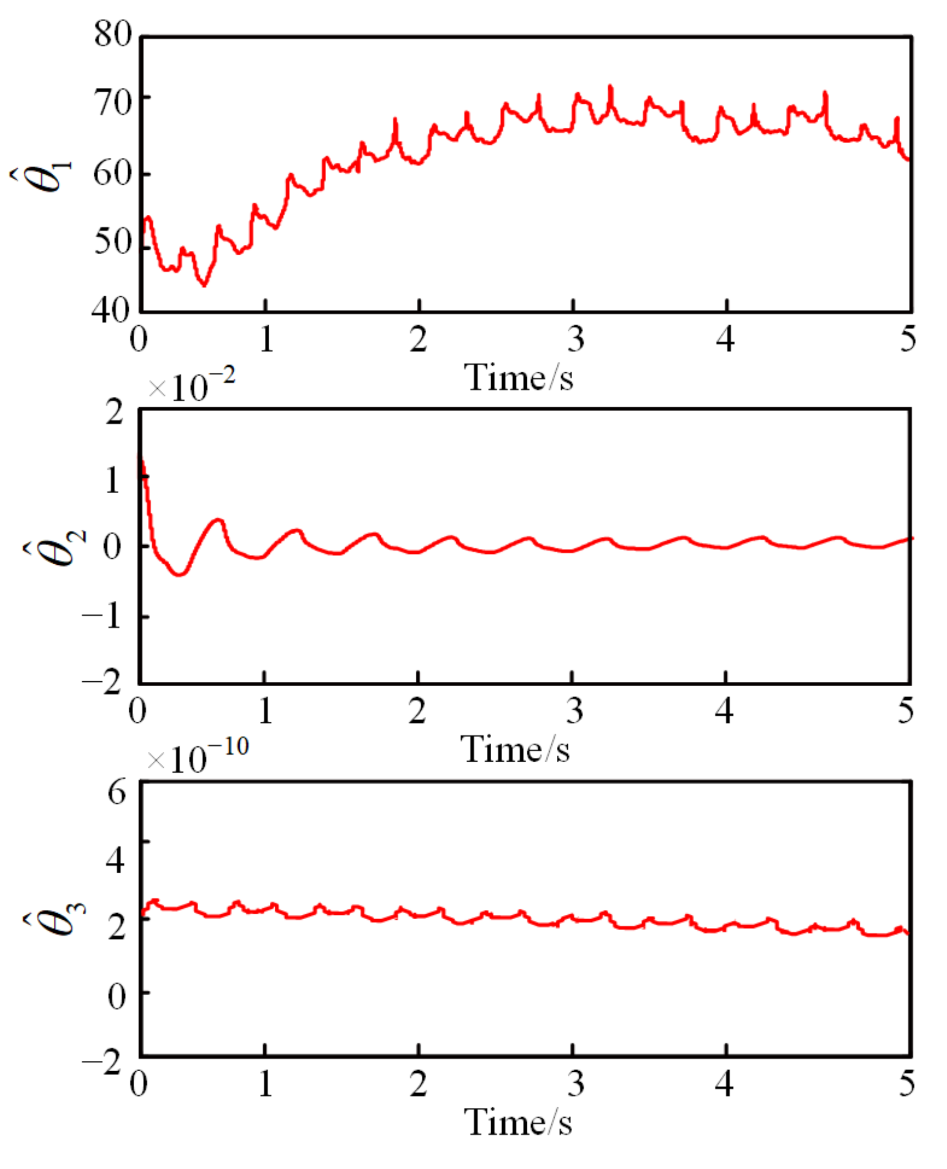
The tracking errors of different controllers with no disturbance are presented in Figure 6. The parameter estimation of the adaptive backstepping controller is shown in Figure 7.
It can be seen from Figure 6 that the displacement tracking error with the conventional PID is much bigger than that with the adaptive backstepping controller and the proposed ABSMC-DO. Owing to the adaptive law (Figure 7), the adaptive parameters of the ABC converge to a stable region in a short time. The tracking performances of the ABC and the proposed ABSMC-DO are both excellent with no disturbance.
4.2.2. Tracking Performance with Uncertain Parameters
The performance robustness with uncertain parameters was further measured by loading mass blocks of 20 kg on the hydraulic cylinder slider; the control parameters of the different controllers remained unchanged. The tracking performance was obtained as shown in Figure 8.
The tracking error of the PID controller increased significantly compared with the no disturbance conditions, resulting in a poor control effect. However, both the ABC and the proposed ABSMC-DO could achieve stability in a relatively short time because of their ability to self-adjust their parameters online. Even if the gain of the controller remained unchanged, a tracking response with a high accuracy could be achieved. The two controllers both had a high control accuracy and excellent tracking performance.
4.2.3. Tracking Performance with External Disturbance
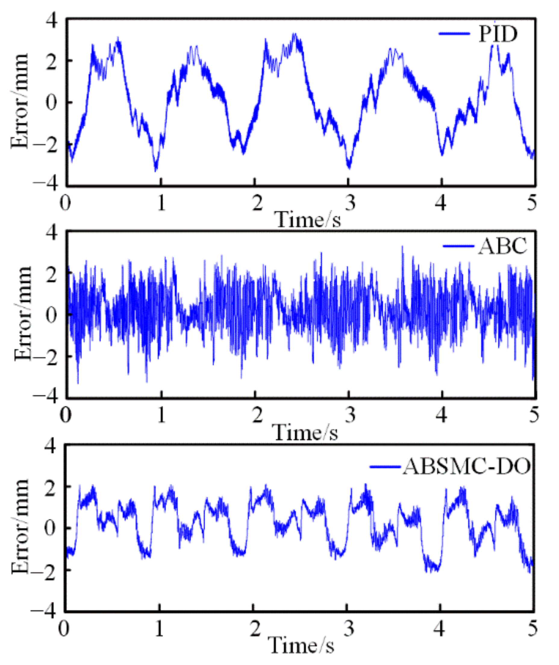
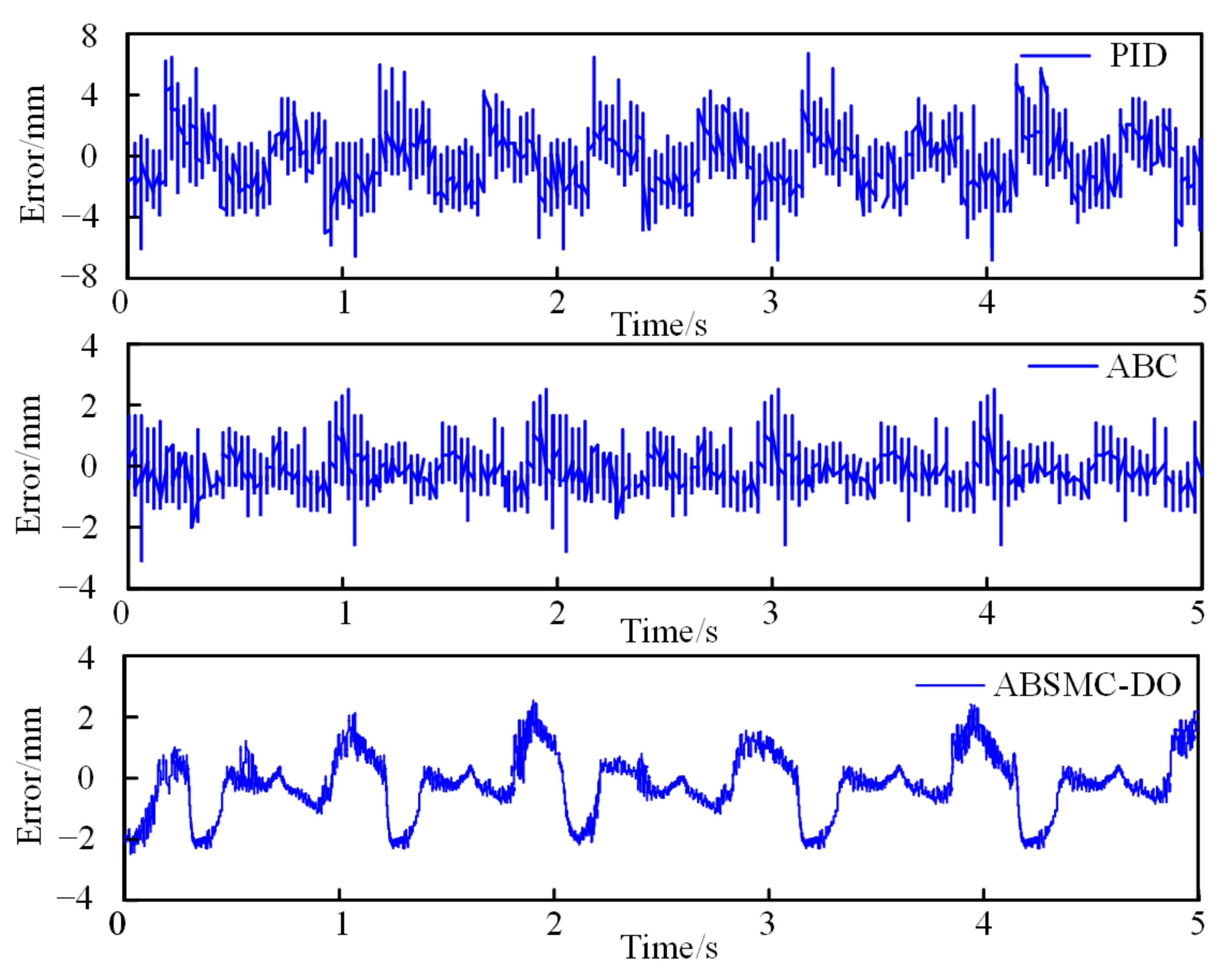
It is a challenge to improve control accuracy owing to the real-time change in the external load in the cutting process. A random external force of 1000 N amplitude was applied at t = 1.5 s and removed at t = 4.5 s to imitate external disturbance. The tracking errors of different controllers are shown in Figure 9.
The conventional PID controller was no longer stable and achieved a large error under external disturbance. The tracking error of ABC increased obviously when external disturbance existed. With the disappearance of the external disturbance, the error was controlled in a small range. However, the proposed ABSMC-DO controller was found to have a better tracking performance, except for the moment of imposing and removing external disturbance.
A quantitative evaluation of the control effect was carried out using the peak tracking errors and root mean square errors (RMSEs), as shown in Table 2.
It can be concluded that the peak errors and RMSEs of the PID controller are both the greatest under different external conditions. The ABC can reach a better control accuracy with no disturbance and uncertain parameters. The controller errors of the proposed ABSMC-DO controller still maintain the smallest under each experimental context, which proves that the designed controller has strong robustness.
4.2.4. Tracking Performance with Prototype Experiment
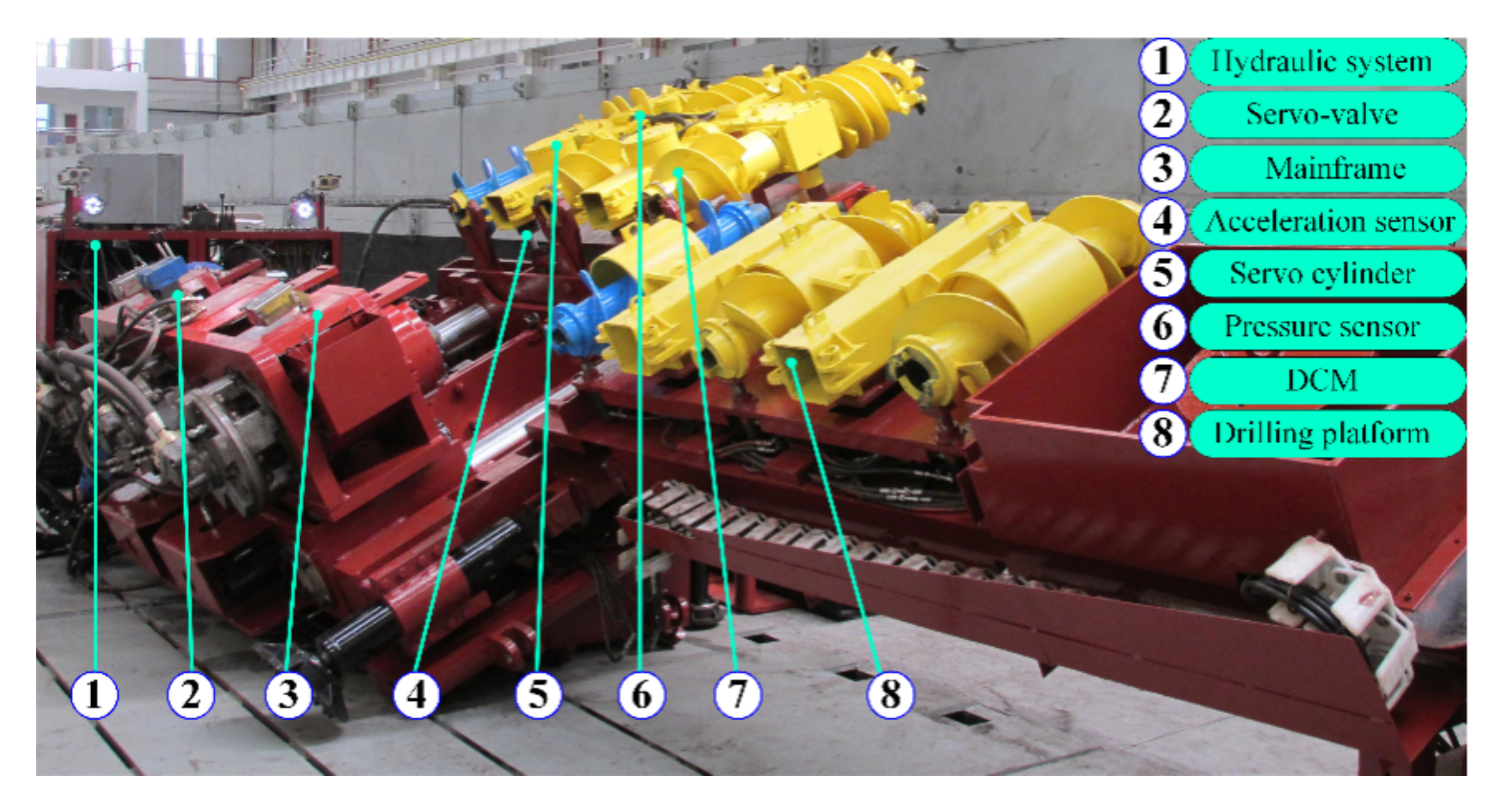
To realize the deviation control of the drill auger during the cutting process, a prototype experiment was carried out, as shown in Figure 10.
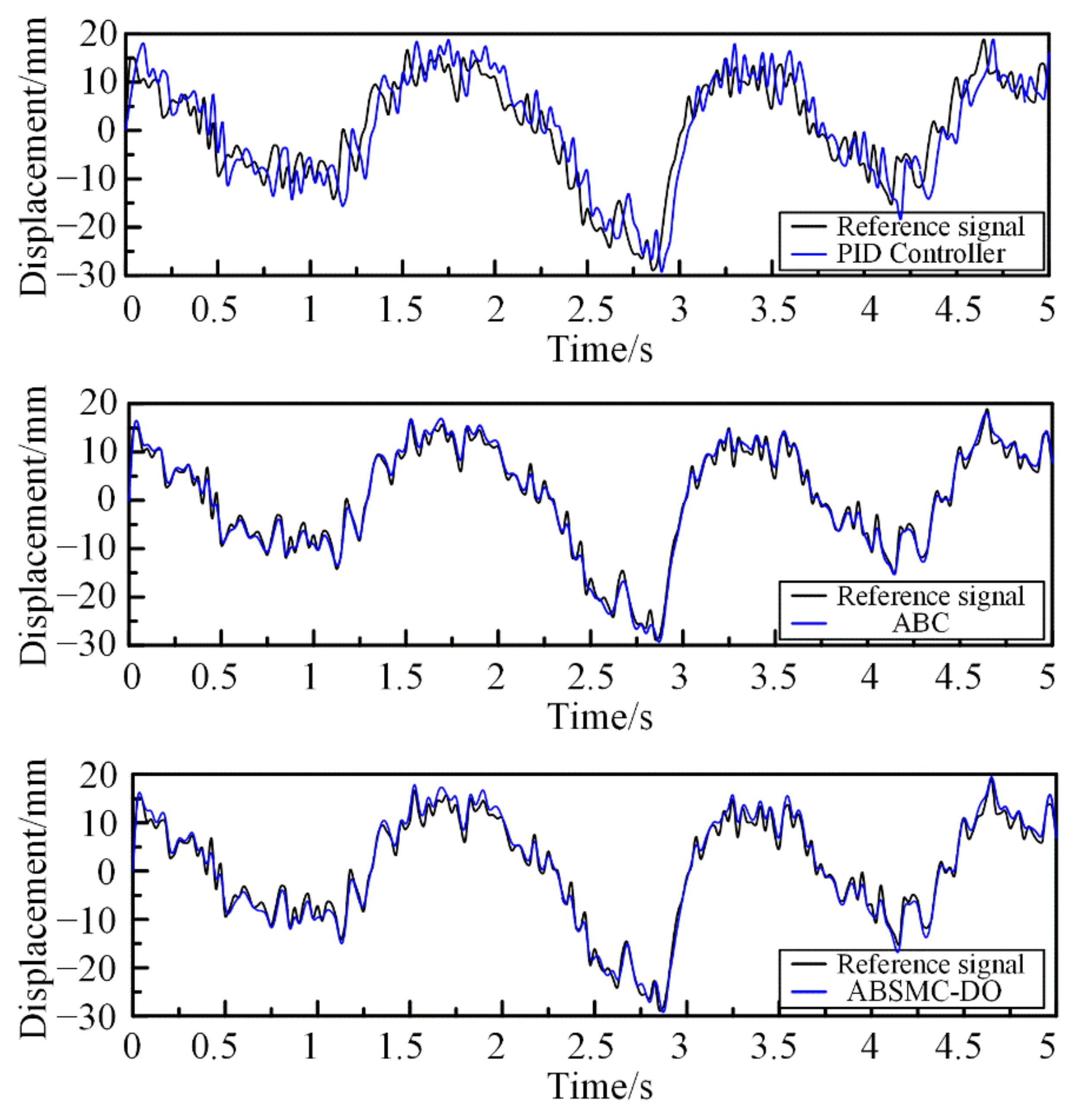
In the actual drilling process, the control system cannot be added to the experimental prototype owing to the small space. Thus, the external disturbances and deviation position data cannot be collected in real time. To solve this problem, we carried out some related experiments [2] on the ground in the early stage and obtained relevant experimental data that can be applied to the experimental prototype to replace the downhole operation environment. This can ensure the reliability of the data. A low-pass filter was used to reduce the influence of noise. The position deviation control results are shown in Figure 11.
As we can see, the signal output waveform showed obvious distortion and phase lag with the conventional PID controller, whose amplitude deviation was the largest. Using the ABC and the proposed ABSMC-DO controller, the tracking effect improved significantly, which indicates that the nonlinear control effect was better in terms of its high response speed and high tracking accuracy.
Further, a normalization analysis was conducted to evaluate the deviation control effect quantitatively. The calculation formula of the normalized root mean square error is as follows:
where ra is the value of the output signal, ya is the value of the reference signal, and L is the length of the reference and output signals. Table 3 lists the RMSE (root mean squared error) of the position tracking with the different controllers. As can be seen, the NRMSE (normalized root mean squared error) based on the PID controller is the largest. However, the ABC and ABSMC-DO controller can achieve a better performance. The ABSMC-DO controller can realize position deviation control under different external conditions.
5. Discussion
In this study, a combined controller consisting of a nonlinear adaptive backstepping controller and a disturbance observer for deviation control was established and verified. Some studies have focused on controller design using the backstepping control method [22,26] and the disturbance observer method [23,31,32], which indicates that these methods are significant. However, most of the available research focuses on control accuracy using high-precision control elements. Our studies tried to combine and improve these two controllers and use a control element with a slightly lower accuracy to achieve the required positioning control for easier industrial application. The results confirm that long-distance directional drilling can be realized under bad downhole working conditions, a finding that can be used in in oil drilling, deep sea exploitation, gas drainage, directional tunneling, and other fields. Besides this, our study shows that both the adaptive backstepping controller and disturbance observer controller cannot reach an excellent tracking performance individually in external disturbance, which is an important and assignable factor. The related research [28,30] has obtained consistent conclusions. Therefore, improving the control accuracy of a single controller is also one of the directions for further research.
However, prototype experiments in this paper were carried out using a ground test and the geological factors were neglected in this paper. Meanwhile, long-distance drilling over 100 m should be considered by fusing sins positioning technology for real-time control. Therefore, further investigation is necessary and will be discussed in future research.
6. Conclusions
In this work, a deflection control mechanism was designed to realize directional drilling. A nonlinear adaptive backstepping controller based on a disturbance observer consisting of an adaptive backstepping controller and a disturbance observer controller was firstly proposed for position tracking control, taking into account the parameter uncertainties and external disturbances. The stability of the overall system with the proposed controller was proven with the help of the Lyapunov theory. To verify the effectiveness of the proposed ABSMC-DO controller, an electro-hydraulic servo displacement control experimental system with matlab xPC target rapid prototyping technology was established. Then, a prototype experiment was conducted to prove the direction drilling performance. The experimental results indicate the following: (a) The displacement tracking error with no disturbance of the conventional PID was much larger than that with the adaptive backstepping controller and the proposed ABSMC-DO. The tracking performances of the ABC and the proposed ABSMC-DO were both excellent with no disturbance. (b) Besides this, the tracking error of the PID controller increased significantly with uncertain parameters, resulting in a poor control effect. However, both the ABC and the proposed ABSMC-DO could achieve stability in a relatively short time thanks to their ability to self-adjust their parameters online. (c) The conventional PID controller was no longer stable and achieved a large error under the conditions of external disturbance. The tracking error of the ABC increased obviously when there was external disturbance. With the disappearance of the external disturbance, the error was controlled in a small range. However, the proposed ABSMC-DO controller achieved a better tracking performance, except for the moment of imposing and removing external disturbance. (d) The NRMSE based on the PID controller was the largest with the prototype experiment. However, the ABC and ABSMC-DO controller could reach a better performance. The ABSMC-DO controller could realize position deviation control under different external conditions. All of the experimental results indicate that the proposed ABSMC-DO controller can yield a more satisfactory position tracking performance than the conventional PID controller and an adaptive backstepping controller.
Author Contributions
Writing—original draft, review, and editing, H.J.; data acquisition, S.L.; investigation, H.J.; methodology, S.L.; validation, H.J.; writing—review and editing, H.J. All authors have read and agreed to the published version of the manuscript.
Funding
This work is supported by the Xuzhou science and technology achievements transformation plan (KC20203), the Project Funded by the Priority Academic Program Development of Jiangsu Higher Education Institutions (PAPD).
Institutional Review Board Statement
Not applicable.
Informed Consent Statement
Not applicable.
Data Availability Statement
The data presented in this study are available on request from the corresponding author.
Conflicts of Interest
The authors declare no conflict of interest.
References
- Yang, D.L.; Li, J.P.; Wang, Y.X.; Jiang, H.X. Research on vibration and deflection for drilling tools of coal auger. J. Vibroeng. 2017, 19, 4882–4897. [Google Scholar] [CrossRef]
- Liu, S.; Ji, H.; Cui, X. Vibration and Deflection Behavior of a Coal Auger Working Mechanism. Shock. Vib. 2016, 2016, 6493859. [Google Scholar] [CrossRef] [Green Version]
- Yuan, Y.; Chen, Z.; Xu, C.; Zhang, X.; Wei, H. Permeability enhancement performance and its control factors by auger mining of extremely thin coal seams. J. Geophys. Eng. 2018, 15, 2626–2641. [Google Scholar] [CrossRef] [Green Version]
- Tang, B.; Cheng, H.; Tang, Y.Z.; Zheng, T.L.; Yao, Z.S.; Wang, C.B.; Rong, C.X. Supporting Design Optimization of Tunnel Boring Machines-Excavated Coal Mine Roadways: A Case Study in Zhangji, China. Processes 2020, 8, 46. [Google Scholar] [CrossRef] [Green Version]
- Liu, Y.Y.; Sun, X.M.; Wang, J.W.; Li, J.B.; Sun, S.J.; Cui, X.B. Study on Three-Dimensional Stress Field of Gob-Side Entry Retaining by Roof Cutting without Pillar under Near-Group Coal Seam Mining. Processes 2019, 7, 552. [Google Scholar] [CrossRef] [Green Version]
- Roman, M.; Josif, B.; Nikolay, D. Development of Position System of a Roadheader on a Base of Active IR-sensor. Procedia Eng. 2015, 100, 617–621. [Google Scholar] [CrossRef] [Green Version]
- Cui, X.X.; Ji, H.F.; Lin, M.X.; Liu, S.Y. Vibration characteristic analysis of the multi-drilling mechanism. J. Vibroeng. 2014, 16, 2722–2734. [Google Scholar]
- Cao, X.W.; Li, X.X.; Yue, F.T. Research and Application of Vibration Measurement While Drilling in the Undersea Coal Mine. J. Coast. Res. 2020, 103, 323–327. [Google Scholar] [CrossRef]
- Li, D.M.; Zhang, Y.Q.; Li, J.; Xia, S. Investigation on sticking for drill rod based on finite element analysis and fuzzy proportion-integration-differentiation. Adv. Mech. Eng. 2019, 11. [Google Scholar] [CrossRef] [Green Version]
- Taheran, F.; Monfared, V.; Daneshmand, S.; Abedi, E. Nonlinear vibration analysis of directional drill string considering effect of drilling mud and weight on bit. J. Vibroeng. 2016, 18, 1280–1287. [Google Scholar]
- Bakhtiari-Nejad, F.; Hosseinzadeh, A. Nonlinear dynamic stability analysis of the coupled axial-torsional motion of the rotary drilling considering the effect of axial rigid-body dynamics. Int. J. Non-Linear Mech. 2017, 88, 85–96. [Google Scholar] [CrossRef]
- Hosseinzadeh, A.; Bakhtiari-Nejad, F. A New Dynamic Model of Coupled Axial–Torsional Vibration of a Drill String for Investigation on the Length Increment Effect on Stick-Slip Instability. J. Vib. Acoust. 2017, 139, 061016. [Google Scholar] [CrossRef]
- Tian, J.L.; Li, G.Y.; Dai, L.M.; Yang, L.; He, H.; Hu, S. Torsional Vibrations and Nonlinear Dynamic Characteristics of Drill Strings and Stick-Slip Reduction Mechanism. J. Comput. Nonlinear Dyn. 2019, 14, 081007. [Google Scholar] [CrossRef]
- Liu, S.Y.; Cui, X.X.; Liu, X.H. Coupling vibration analysis of auger drilling system. J. Vibroeng. 2013, 15, 1442–1453. [Google Scholar]
- Lueke, J.S.; Ariaratnam, S.T. Surface Heave Mechanisms in Horizontal Directional Drilling. J. Constr. Eng. Manag. 2005, 131, 540–547. [Google Scholar] [CrossRef]
- Manacorda, G.; Miniati, D.; Dei, D.; Scott, H.F.; Pinchbeck, D. Development of a bore-head GPR for Horizontal Directional Drilling (HDD) equipment. In Proceedings of the XIII International Conference on Ground Penetrating Radar, Lecce, Italy, 21–25 June 2010. [Google Scholar]
- Inyang, I.J.; Whidborne, J.F. Bilinear modelling, control and stability of directional drilling. Control. Eng. Pract. 2019, 82, 161–172. [Google Scholar] [CrossRef] [Green Version]
- Kim, J.; Myung, H. Development of a Novel Hybrid-Type Rotary Steerable System for Directional Drilling. IEEE Access 2017, 5, 24678–24687. [Google Scholar] [CrossRef]
- Gao, B.W.; Shao, J.P.; Yang, X.D. A compound control strategy combining velocity compensation with ADRC of electro-hydraulic position servo control system. ISA Trans. 2014, 53, 1910–1918. [Google Scholar] [CrossRef]
- Lin, S.H.; An, G.C.; Huang, J.H.; Guo, Y. Robust Backstepping Control with Active Damping Strategy for Separating-Metering Electro-Hydraulic System. Appl. Sci. 2020, 10, 277. [Google Scholar] [CrossRef] [Green Version]
- Feng, L.J.; Yan, H. Nonlinear Adaptive Robust Control of the Electro-Hydraulic Servo System. Appl. Sci. 2020, 10, 4494. [Google Scholar] [CrossRef]
- Yang, M.X.; Zhang, Q.; Lu, X.L.; Wang, X. Adaptive Sliding Mode Control of a Nonlinear Electro-hydraulic Servo System for Position Tracking. Mechanika 2019, 25, 283–290. [Google Scholar] [CrossRef] [Green Version]
- Wos, P.; Dindorf, R. Adaptive Control of the Electro-Hydraulic Servo-System with External Disturbances. Asian J. Control. 2013, 15, 1065–1080. [Google Scholar] [CrossRef]
- He, Z.; Guan, W.-L.; Feng, J.; Gao, Q. Mathematical modelling and backstepping adaptive sliding mode control for multi-stage hydraulic cylinder. Int. J. Model. Identif. Control. 2018, 30, 322–342. [Google Scholar] [CrossRef]
- Guo, Q.; Sun, P.; Yin, J.-M.; Yu, T.; Jiang, D. Parametric adaptive estimation and backstepping control of electro-hydraulic actuator with decayed memory filter. ISA Trans. 2016, 62, 202–214. [Google Scholar] [CrossRef]
- Wang, W.P.; Wang, B. Disturbance observer–based nonlinear energy-saving control strategy for electro-hydraulic servo systems. Adv. Mech. Eng. 2017, 9, 11–18. [Google Scholar] [CrossRef] [Green Version]
- Zhu, Z.-C.; Li, X.; Shen, G.; Wei, D. Wire rope tension control of hoisting systems using a robust nonlinear adaptive backstepping control scheme. ISA Trans. 2018, 72, 256–272. [Google Scholar] [CrossRef]
- Choux, M.; Hovland, G. Adaptive Backstepping Control of Nonlinear Hydraulic-Mechanical System Including Valve Dynamics. Model. Identif. Control. 2010, 31, 35–44. [Google Scholar] [CrossRef] [Green Version]
- Ji, X.; Wang, C.; Zhang, Z.; Chen, S.; Guo, X. Nonlinear adaptive position control of hydraulic servo system based on sliding mode back-stepping design method. Proc. Inst. Mech. Eng. Part I J. Syst. Control. Eng. 2020. [Google Scholar] [CrossRef]
- Yang, G.C.; Yao, J.Y. Nonlinear adaptive output feedback robust control of hydraulic actuators with largely unknown modeling uncertainties. Appl. Math. Model. 2020, 79, 824–842. [Google Scholar] [CrossRef]
- Yang, G.Z.; Yao, J.Y. High-precision motion servo control of double-rod electro-hydraulic actuators with exact tracking performance. ISA Trans. 2020, 103, 266–279. [Google Scholar] [CrossRef]
- Zheng, J.; Yao, J. Robust adaptive tracking control of hydraulic actuators with unmodeled dynamics. Trans. Inst. Meas. Control. 2019, 41, 3887–3898. [Google Scholar] [CrossRef]
- Guo, K.; Wei, J.H.; Fang, J.H.; Feng, R.L.; Wei, J.H. Position tracking control of electro-hydraulic single-rod actuator based on an extended disturbance observer. Mechatronics 2015, 27, 47–56. [Google Scholar] [CrossRef]
- Guo, K.; Wei, J.H.; Tian, Q.Y. Disturbance observer based position tracking of electro-hydraulic actuator. J. Cent. South Univ. 2015, 22, 2158–2165. [Google Scholar] [CrossRef]
- Kasac, J.B.; Stevanovic, S.; Zilic, T.; Stepanic, J. Robust output tracking control of a quadrotor in the presence of external disturbances. Trans. FAMENA 2013, 37, 29–42. [Google Scholar] [CrossRef] [Green Version]
- Hu, X.; Du, J.L.; Li, J.; Sun, Y. Asymptotic Regulation of Dynamically Positioned Vessels with Unknown Dynamics and External Disturbances. J. Navig. 2020, 73, 253–266. [Google Scholar] [CrossRef]
- Teoh, J.N.; Du, C.; Guo, G.; Xie, L. Rejecting high frequency disturbances with disturbance observer and phase stabilized control. Mechatronics 2008, 18, 53–60. [Google Scholar] [CrossRef]
- Van Nguyen, T.; Ha, C. Sensor Fault-Tolerant Control Design for Mini Motion Package Electro-Hydraulic Actuator. Processes 2019, 7, 89. [Google Scholar] [CrossRef] [Green Version]
Figure 1.
Mining technology of coal auger.

Figure 2.
Structure diagram of the deviation control mechanism (DCM).

Figure 3.
Dynamic model of the deviation control mechanism.

Figure 4.
Control diagram of the adaptive backstepping control based on the disturbance observer (ABSMC-DO).
Figure 4.
Control diagram of the adaptive backstepping control based on the disturbance observer (ABSMC-DO).

Figure 5.
Electro-hydraulic servo displacement control experimental system. PID, proportion integral derivative.
Figure 5.
Electro-hydraulic servo displacement control experimental system. PID, proportion integral derivative.

Figure 6.
Tracking errors of different controllers with no disturbance. ABC, adaptive backstepping controller.
Figure 6.
Tracking errors of different controllers with no disturbance. ABC, adaptive backstepping controller.

Figure 7.
Parameter estimation of the adaptive backstepping controller.

Figure 8.
Tracking errors of different controllers with no disturbance.

Figure 9.
Tracking errors of different controllers with external disturbance.

Figure 10.
Experiment prototype for position deviation control.

Figure 11.
Position deviation control results of the prototype test.


Table 1.
Main parameters of the electro-hydraulic servo displacement control experimental system.
| Parameters | Symbol | Values | Units |
|---|---|---|---|
| Supply pressure | Ps | 15 × 106 | Pa |
| Effective bulk modulus | βe | 7.0 × 10⁸ | Pa |
| Volume of hydraulic cylinder | V | 0.62 × 10⁻⁴ | m3 |
| Effective area of hydraulic cylinder | Ap | 3.6 × 10⁻³ | m2 |
| Total mass | mp | 100 | kg |
| Viscous damping coefficient | Bm | 5652 | N·m·s/rad |
| Flow coefficient of servo valve | Cd | 0.602 | —— |
| Gain of servo valve | Kq | 2.6 × 10⁻⁴ | m/A |
| Natural frequency of servo valve | ωsv | 150 | rad/s |
| Area gradient of servo valve core | ω | 1.63 × 10⁻³ | m |
Table 2.
Position tracking performance index under different controllers. RMSE, root mean square error; PID, proportion integral derivative; ABC, adaptive backstepping controller; ABSMC-DO, adaptive backstepping control based on the disturbance observer.
Table 2.
Position tracking performance index under different controllers. RMSE, root mean square error; PID, proportion integral derivative; ABC, adaptive backstepping controller; ABSMC-DO, adaptive backstepping control based on the disturbance observer.
| Controller | No Disturbance | Uncertain Parameters | External Disturbance | |||
|---|---|---|---|---|---|---|
| Peak Error/mm | RMSE | Peak Error/mm | RMSE | Peak Error/mm | RMSE | |
| PID | 3.2 | 1.16 | 7.1 | 3.32 | 28.2 | 10.34 |
| ABC | 3.6 | 1.02 | 3.7 | 1.33 | 9.1 | 4.26 |
| ABSMC-DO | 2.3 | 0.84 | 2.9 | 1.14 | 4.7 | 1.62 |
Table 3.
Normalized performance index of position control under different controllers. NRMSE, normalized RMSE.
Table 3.
Normalized performance index of position control under different controllers. NRMSE, normalized RMSE.
| Controller | Max Signal | RMSE | NRMSE |
|---|---|---|---|
| PID | −0.0295 | 11.1009 × 10⁻³ | 37.63% |
| ABC | −0.0295 | 5.7584 × 10⁻³ | 19.52% |
| ABSMC-DO | −0.0295 | 4.2097 | 14.27% |
Publisher’s Note: MDPI stays neutral with regard to jurisdictional claims in published maps and institutional affiliations. |
© 2021 by the authors. Licensee MDPI, Basel, Switzerland. This article is an open access article distributed under the terms and conditions of the Creative Commons Attribution (CC BY) license (http://creativecommons.org/licenses/by/4.0/).
Share and Cite
MDPI and ACS Style
Ji, H.; Liu, S. Position Deviation Control of Drilling Machine Using a Nonlinear Adaptive Backstepping Controller Based on a Disturbance Observer. Processes 2021, 9, 237. https://0-doi-org.brum.beds.ac.uk/10.3390/pr9020237
AMA Style
Ji H, Liu S. Position Deviation Control of Drilling Machine Using a Nonlinear Adaptive Backstepping Controller Based on a Disturbance Observer. Processes. 2021; 9(2):237. https://0-doi-org.brum.beds.ac.uk/10.3390/pr9020237
Chicago/Turabian StyleJi, Huifu, and Songyong Liu. 2021. "Position Deviation Control of Drilling Machine Using a Nonlinear Adaptive Backstepping Controller Based on a Disturbance Observer" Processes 9, no. 2: 237. https://0-doi-org.brum.beds.ac.uk/10.3390/pr9020237
Note that from the first issue of 2016, this journal uses article numbers instead of page numbers. See further details here.