
An Investigation of Heat Transfer Performance in an Agitated Vessel


1
LERMA Lab, International University of Rabat College of Engineering, Sala El Jadida 11100, Morocco
2
LPAMM Lab, Faculty of Sciences and Technology of Mohammadia, University of Hassan II Casablanca, Mohammadia 28013, Morocco
*
Authors to whom correspondence should be addressed.
Processes 2021, 9(3), 468; https://0-doi-org.brum.beds.ac.uk/10.3390/pr9030468
Submission received: 27 December 2020
/
Revised: 5 February 2021
/
Accepted: 6 February 2021
/
Published: 5 March 2021
(This article belongs to the Special Issue Enhancement of Heat Transfer and Fluid Flow)
Abstract
:Agitated vessels (or mechanically stirred reactors) are heat exchange devices that are most widely used in many chemical and biochemical process industries, such as anaerobic digestion process. The mixing and heat transfer performances in these vessels are of crucial importance for increasing the energy efficiency in both batch and continuous processes. In this paper, a series of experiments were conducted to investigate heat transfer performance in agitated vessels for various configurations. In fact, this study examines the effects of heat transfer geometry (wall jacket and helical coils), heating power, and stirring speed, on the heating performance of two stirred fluids—water alone and a mixture of water and food waste. The experiments were conducted using a jacketed insulation tank with a helical coil and a propeller agitator. In each experiment, a transient method, based on measuring the temperature dependency on time, and solving the unsteady enthalpy balance, was used to determine the overall heat transfer coefficients between the agitated fluid and the heating surface. Finally, an extensive analysis of the reduced data was conducted based on temperature, heating time, heat transfer rate, heat transfer coefficient, and thermal resistance. The main finding was that the presence of food waste in agitated vessels reduces the heat rate of the agitated fluid with an average of 18.13% and 49.51%, respectively, for the case of JHX and CHX, and creates additional fouling, which further limits the heat transfer.
1. Introduction
The principles of heat transfer have a vast application in processing industries. For instance, heat transfer represents one of the main operations that occur in bioreactors (i.e., agitated reactors) and could affect the anaerobic digestion (AD) process. This latter is a sequence of biological processes, in which microorganisms degrade the organic matter in the absence of oxygen (anaerobic). This process allows recovering energy in the form of biogas (a mixture of methane and carbon dioxide). This process is mainly affected by the temperature and the mixing mode. The AD process can take place at three temperature ranges, namely psychrophilic (below 25 °C), mesophilic (25–45 °C), and thermophilic (45–70 °C), where each range has its advantages and disadvantages. Furthermore, increasing the methane yield in anaerobic digesters requires some degree of stirring, in order to facilitate the access of bacteria to nutrients [1] and to enhance the thermal delivery to the digesters’ contents [2]. The mixing employed in anaerobic digesters is carried out either through impellers and paddles (mechanical), gas injectors (pneumatic), liquid pumps (hydraulic), or a combination of these techniques. However, continuously stirred tank reactor (CSTR) remains the most used type of bioreactors in the AD process [1,3,4].
Most bioreactors are fitted with heating elements in the form of immersed copper heat exchangers (HX), electric resistors, double walled tanks [5,6,7], or tubular baffle [8]. The aim is to maintain the reaction at a desired temperature setpoint, especially in regions where temperature variations are extreme. On this basis, to manage the progress of the AD process, we must first study the heat transfer within the agitated tank and the different factors it affects. Often, this type of study requires determining the overall heat transfer coefficient and the various factors that influence it.
Thus, the entire mechanically stirred reactor can be split into two main components, the process side (i.e., the agitated interior bulk fluid) and the heater (e.g., heat exchangers). According to the literature, most research work often focus on one side of the reactor by investigating the effect of different parameters on its thermal behavior. For example, the influence of the geometric parameters of the baffles [9], the type and size of the wheel [10], and the non-ideal mixture [11] on the heat transfer coefficient were studied using different working fluids. For instance, Strek et al. [12] studied the effects of the geometrical parameters of non-standard baffles on heat transfer coefficient, and they proposed the optimal geometry of baffles in an agitated vessel. On the other hand, they showed that the properties of fluids also affect the overall transfer coefficient. In Silvia’s study [13], CFD (computational fluid dynamics) was applied to obtain a Nusselt number correlation for a double-shell stirred tank equipped with a Rushton six-blade turbine. Dostal et al. [14] measured the heat transfer coefficients on coils of helical pipes using the transient method, in an agitated tank with a multistage impeller. Wang et al. [15] numerically studied heat transfer in a reactor with improved impellers blade. This study showed the influence of heat and mass transfer developing from the impeller diameters, the distance between the two impellers, the rotational speed, and the installation height of the bottom impeller. Chen et al. [16] in their paper presented a study of convective heat transfer of non-Newtonian fluids in a stirred tank with different impellers. The lattice Boltzmann method was applied as an efficient technique in modeling the heat transfer process. Furthermore, they present the heat transfer effect of a stirred tank by stirring the impeller with a combined oscillating-rotation type of motion. Perarasu et al. [17] experimentally studied the heat transfer characteristics of the Al2O3-water Nano-fluid in a stirred vessel, with a propeller agitator. Simulation results showed that the use of nanofluids improved the heat transfer by convection. Empirical correlations developed for the Nusselt number corresponded to the experimental data by ±10%.
After studying the heat transfer in a stirred container rolled up with a variable heat supply, Perarasu et al. [18] separately determined empirical correlations for each used agitator (propeller and disc turbine). They concluded that mixing by the turbine agitator aids more heat transfer than mixing by the propeller agitator. In Parinaz’s work [19], the convective heat transfer SiO2/water nanofluid in the shell side of a jacketed reactor was studied experimentally and numerically by the finite volume method and the k-ε turbulence model. They mainly showed the effect of nanofluid concentration in heat transfer. In fact, two empirical correlations were proposed for predicting the Nusselt number for water and nanofluid. The obtained simulation results showed a difference of approximately 7% against experimental results.
The work presented in [20] aimed to carry out an experimental study to obtain the heat transfer coefficients, for Newtonian and non-Newtonian fluids. The study was conducted at a constant wall temperature as a boundary condition, in a laminar flow inside a helical coil. A correlation of the Nusselt number as a function of Péclet, generalized Dean and Weissenberg numbers was mentioned. In Matthias’ article [21], the heat transfer characteristics of agitated single-use bioreactors were determined both by transient and steady state experiments. The heat transfer coefficient on the envelope side was calculated by the Wilson plot method, while the convective heat transfer coefficient on the mixed liquid side was measured, based on transient heating and cooling of the Newtonian liquid, in a stirred double-jacketed container [22] and with tubular baffles [23]. The measurement results are summarized by Nusselt number correlations. A CFD model was developed to simulate the heat transfer between a helical coiled tube and a high solid fermentation slurry in a home biogas digester. The simulation results were verified and compared against those obtained from experiments [24].
Despite the extensive work from current literature, studying the effect of heterogeneous fluids, such as a mixture of water and food waste heat transfer in mechanically stirred reactors, is still required. To this end, the work presented in this paper aims to further investigate and study the effect of stirring speed, mass flow rate of the heating fluid, type of heating element, and the type of the stirring fluid on the thermal behavior of an agitated reactor with a propeller impeller. For this purpose, the overall heat transfer coefficient was identified, and the local heat transfer coefficients and thermal resistance were calculated. In summary, the main contributions of this work are two folds:
- Extensive experimentations were conducted to investigate the heat transfer performance in agitated vessels for various configurations. Results are reported to assess the effects of heat transfer geometry, heating power, and stirring speed, on the heating performance for both water and a mixture of water and food waste.
- Performance evaluation and analysis was conducted based on temperature, heating time, heat transfer rate, heat transfer coefficient, and thermal resistance. Results were reported and compared against those obtained from experiments.
2. Materials and Methods
2.1. Experimental Unit Description
The schematic view of the experimental unit, which was used in this study, is shown in Figure 1. It is composed of a double-jacketed, stainless-steel tank with a capacity of 1.2 m3, insulated by a polystyrene jacket. A coil stainless steel tube with an internal diameter of 6 mm and an external diameter of 7 mm, 7 spirals, totaling an area of 0.05 m2, and four vertical stainless-steel baffles regularly positioned by 90° along the vessel wall. A propeller agitator of diameter 35 mm with 3 blades was used. The agitator was driven by a nylon gear motor with a power range of 2.2 W, its stirring speed ranged from 20 min−1 to 330 min−1, with an uncertainty of 0.1%. The experimental unit also included—(i) a hot water tank equipped with an electrical heater having a maximum power of 3 kW, and the temperature water inside it was set to 50 °C, (ii) TIC temperature regulator with a hysteresis of 0.2 °C and a maximum temperature setpoint of 70 °C, (iii) centrifugal pumps for the transport of hot fluid, (iv) three platinum resistance thermometers (PT 100) with an accuracy of ±0.15 °C were used, two were used to measure the fluid inlet and outlet temperatures in the heat exchanger side of the stirred tank, while the other one was used to measure the stirred medium temperature, (v) paddle flow meter with an accuracy of ±0.5% was used to measure the volumetric flow rate in heat exchangers, and (vi) the manual control valve (V1) was used to regulate the flow rate of warm fluid.
All data retrieved by sensors were transmitted to a remote computer where they were stored and processed through a software tool. Figure 2 shows the main tank’s components, while Table 1 and Table 2 presents the geometric parameters and the thermophysical properties of the agitated liquid, respectively. Regarding the thermal conductivity and specific heat of the mixture (W + FW), we determined them using the mass average.
2.2. Mixture Composition
Water (W) alone and a mixture of water (80 wt.%) and food waste (20 wt.%), as shown in Figure 3a, were separately used as working fluids. Food waste (FW) was collected from a local food market. It was composed of potatoes (36.7 wt.%), onions (30 wt.%), tomatoes (13.3 wt.%), and lettuce (20 wt.%). After the collection process, FW was finely ground in order to reduce particle size (see Figure 3b).
2.3. Experimental Conditions
Water is the heating medium, which is pumped through the heating geometry (jacket wall and helical coil). The hot water is fed to the experiments at a variable inflow temperature and flows rate . For each of the stirred fluid, different and were adopted. For the agitation speed , we opted for 3 values, 0 (without agitation), 165, and a maximum value of 330 min−1. For the mass flow rate of the heating liquid , we took the values 0.02, 0.04, and 0.006 kg/s. The initial temperature of the agitated fluid inside the tank was kept at a constant 26 °C for each experiment.
Eighteen experiments were carried out with water as the stirred fluid—nine of them for the case of the jacketed heat exchanger (JHX), while the rest was dedicated to the helical coil heat exchanger (CHX). Likewise, another set of eighteen experiments was carried out under the same conditions using W + FW as the stirring fluid. The reactor was cleaned in order to avoid interferences between experiments. In total, 36 experiments were performed. The design of the experiments is detailed in Table 3. Each experiment lasted 30 min, since after this duration the temperature become constant (system equilibrium).
Before starting the measurements, the mass of stirred fluid was measured. Then, at a constant agitation rotational speed, the stirred fluid in the tank was heated by hot water flowing through the heat exchanger. The temperature of the stirred liquid was measured together with the inlet and outlet temperatures of the water flowing inside the heat exchanger. The experimental curves, depicted in Figure 4, show the evolution over time of the temperatures, which were measured for a specific stirring speed and flow rate. From this figure, the values of inlet and outlet temperature of the hot fluid fluctuated slightly. This is because electric heating was automatically activated when the average temperature of the hot water in the heating cylinder was lower than the set temperature.
2.4. Heat Transfer Parameters
The heat transfer rate between the heat transfer element and the agitated liquid depends on many parameters, such as heat exchanger, geometry, agitated liquid properties, fluid rheology (Newtonian or Non-Newtonian fluids), type of agitator, and its rotation rate. The influence of most of these parameters could be represented by the overall heat transfer coefficient U. The heat transfer rate between the agitated liquid and the heating fluid could be expressed by Equation (1).
where U, A, and are the overall heat transfer coefficient, heat exchange surface, and the temperature difference between the process side and the utility fluid, respectively. It is worth noting that the utility should be understood as the fluid used to promote the heat exchange (e.g., steam, hot water, oil). In our case, we used the hot water.
The relation between the heat transfer coefficient and other parameters, e.g., geometry and stirred speed could be described by the dimensionless numbers, Reynolds number (Re), Prandtl number (Pr), and Nusselt number (Nu). Such a relation is usually written as follows (Equations (2)–(5)), where D, Do, λ, ρ, μ, cp, and h are the vessel diameter, the impeller diameter, the thermal conductivity of the fluid, the density of the fluid, the dynamic viscosity of the fluid, the specific heat, and the heat transfer coefficient, respectively. A general relation between all these dimensionless numbers is usually described by Equation (5) [25].
3. Results and Discussions
3.1. Temperature Measurement
Experiments were conducted and the average temperature inside the reactor was measured. Initially, we started by testing the water alone as an agitated fluid. These experiments were aimed at studying the effect of the stirring speed and the type of the exchanger on the thermal behavior of the stirred medium. They constituted a basis for studying the effect of the mixture of the food waste as an agitated fluid on the heat transfer inside the reactor. In order to study the reproducibility of the experiments, a test was repeated three times (Test 1–3) for the coil heat transfer surface, with a flow rate of 0.04 kg/s and an agitation speed of 0 min−1, in the case of water as an agitated fluid Figure 5a. From this figure, we observe that the obtained results were close for the three tests. Furthermore, Figure 5b illustrates the uncertainty between these tests. From this figure, we could observe that the uncertainty varied between 0 and ±0.83 °C. From the small value of this uncertainty, we could conclude that our experiment was reproducible.
The time required to heat the agitated media increases when using the jacket heat exchanger, Figure 6. This could be explained by the fact that the heat transfer in the jacketed heat exchangers is limited. Unlike coil heat exchangers, which provide a higher overall heat transfer coefficient [17], this behavior is due to the low value of the overall coefficient of the heat transfer. It is worth noting that we performed the same study for solid waste as stirred fluid and we reached the same conclusion. Whatever the agitated media, it is preferable to use a coil heat exchanger in order to reduce the heating time of the reactor.
The effect of the stirring speed in the agitated media was also investigated. Figure 7 shows the temporal evolution of the agitated fluid temperature, using both water and solid waste mixture as an agitated fluid, for different stirring speeds and for a specific flow rate (). As depicted in Figure 7a, when the intensity of the stirring speed was increased, on the one hand, the agitated fluid temperature increased, and on the other hand the time of heating decreased, with an average up to 30% for water and 50% for W + FW. This was caused by the increase of the Reynolds Number (Equation (2)), which directly led to the improvement of the heat transfer coefficient. Additionally, the differences in temporal evolution of the agitated fluid temperatures denoted different heat exchange mechanisms. Natural convection for N = 0, while forced convection for N > 0. Figure 7b illustrates the temperature evolution of the W + FW. It shows a similar trend when using the water as an agitated fluid. However, when the stirring speed was null, the agitated fluid temperature increased tardily in relation to the other speed intensities. This might be due to the adhesion of some food waste particles on the surface of the heat transfer.
3.2. Determining the Value of U
The transient method was used in this paper for the measurement of the heat transfer coefficient. This method was based on time monitoring, the temperature of an agitated liquid and solving the unsteady enthalpy balance. Despite the mathematical analysis of data, using this method is generally more difficult. It can generally be carried out more quickly, since it is not necessary to wait for a stationary situation. To start calculating U, a differential energy balance was conducted in the agitated tank.
where, , , , , h, , are energy accumulated in the control volume, the heat loss, work provided to fluid by the rotation of the mechanical impeller in control volume, flow rate of the working fluid, enthalpy of the working fluid, kinetic energy of the working fluid, and the potential energy of the working fluid, respectively.
In the case of the discontinuous stirred tank, resulting work from the mechanical impeller rotation was disregarded . Furthermore, as the tank was wrapped in nylon insulation, the heat loss in the external environment was not considered . Moreover, by neglecting the changes in kinetic and potential energy, physical properties were calculated at average temperatures for both hot and cold fluids. By applying the above-mentioned hypothesis to (Equation (6)), the energy balance was reduced to (Equation (7)).
The term on the right-hand side of (Equation (7)) represents the heat exchanged between the agitated media and the heat exchanger fluid at any instant of time. In addition, as we saw in (Equation (1)), the overall heat transfer coefficient, U, was the coefficient of proportionality between the heat flow per unit heat transfer area and the temperature difference.
The temperature difference was the thermodynamic driving force for this heat flow. For discontinuous operations, when there was a considerable temperature difference between the entrance and exit temperatures of the exchanger fluid, the temperature driving force was defined as the log mean temperature difference, . Calling the utility entrance temperature and the utility exit temperature, and T the mean temperature of the stirred fluid in the tank, the temperature driving force could be computed using Equation (9) [18].
Replacing (Equation (9)) for (Equation (8)) and then for (Equation (7)), we reach the differential expression of the bulk temperature in terms of time, as illustrated in (Equation (10)).
The main parameter of (Equation (10)) was the U, which was a function of the conduction, convection, and radiation mechanisms, as shown in (Equation (11)).
where , , are the convection, conduction, and the radiation thermal resistances, respectively.
In certain processes, where temperatures were lower than 800 °C [8], the radiation was neglected. As a result, the U was commonly considered a function of conduction, the internal and the external convection coefficients, only in a system analysis, as illustrated in (Equation (12)); where and are, respectively, the heat exchange coefficients on the agitated fluid side and the heat exchanger side. These were a function of the heat transfer surface geometry of the tank, the physical properties of the cold and hot fluids, the discharge, and the fluid rheology (Newtonian and Non-Newtonian fluids). is the process-side fouling factor, which we neglected for the case of water, because we used a clean reactor.
where , and are the wall thermal conductivity, and inner and the outer diameter of the heat exchanger, respectively.
In order to identify U, we can solve (Equation (10)) and obtain a temporal evolution of the temperature of the agitated liquid. The inlet and outlet temperatures, which were measured with the temperature of the stirred container T, changed over time, therefore, we must use a numerical method to solve (Equation (10)). In our case, we used the function ode45, which is the standard MATLAB solver for ordinary differential equations (ODE). This function implements a Runge-Kutta method with a variable time-step for an efficient calculation. The solution gives us the time profile of the numerical temperature for a given overall heat transfer coefficient U. The real heat transfer coefficient U should ensure small deviations from the time profile of numerical temperature by comparing it to the measured profile . Mathematically, we could look for such a value of U that minimizes the sum of squares of the deviations.
Using this condition, we get an optimal value of the overall heat transfer coefficient U, which best fits the experimental data.
The time course of the identified and the experimental agitated fluid temperature in the jacketed heat exchanger was shown in Figure 8, where N = 165 min−1 and = 0.02 kg/s, both for water and mixture of water and food waste. These curves were close with a maximum deviation of 1.61% for water, as shown in Figure 8a, and 2.14% for W + FW, as indicated in Figure 8b. Consequently, it could be said with certainty that the identified values of U best correspond to the experimental data.
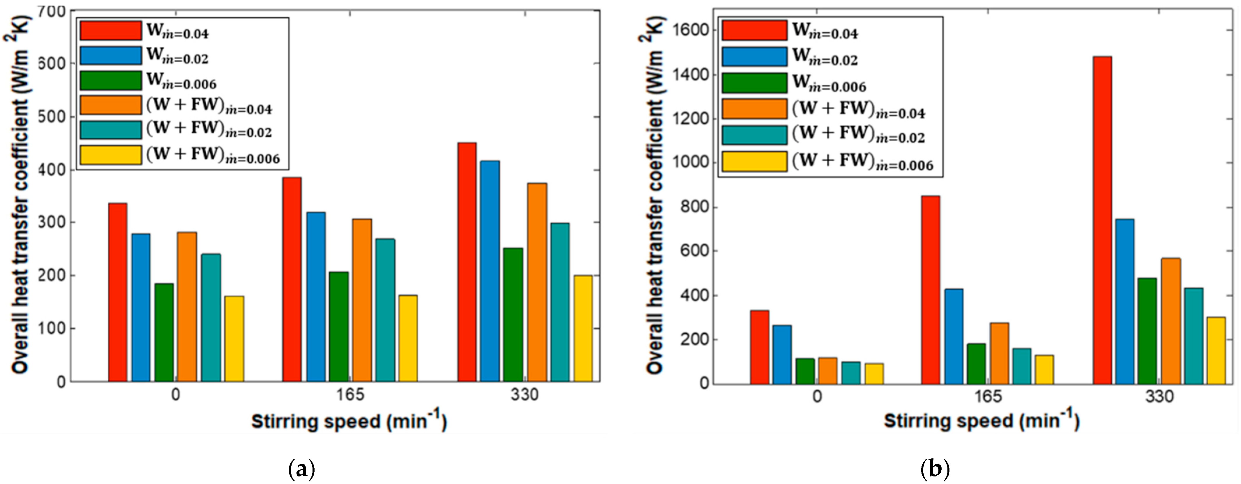
The heat exchange in stirred tanks occurs primarily according to the rotation speed of the impeller and the overall circulation of the fluid, which promotes more efficient heat transfer between the fluid and the heat transfer surfaces. In other words, this was due to increased turbulence in the stirred tank (mixture intensifies the turbulence in the medium), which stimulated higher heat transfer by convection. The effects of the previously mentioned parameters on the heat transfer coefficient are depicted in Figure 9. When water was used as an agitated fluid, by increasing the stirring speed, the value of the overall heat transfer coefficient U increases, on average, by 18% for the JHX and 98% for the CHX. This was also proven by Rosa et al. in [8] and Dostal et al. in [13]. In the first work, they used four stirring speed values (100, 400, 700, and 1000 min−1). However, on the second, they worked with a varying range of speed between 50 min−1 and 402 min−1 and found that U increased with an average of 6.83%. In the W + FW scenario, the overall heat transfer coefficient increased with increasing stirring speed, by an average of 13% and 104%, respectively, for JHX and CHX. This was confirmed by the work of Dohi et al. in [26], which showed that at lower turbine speeds, the majority of solid particles lay on the bottom of the tank. As the speed of the wheel increased, the solid particles were quickly suspended through the tank. This resulted in a sharp change in the slope of the curve for the solid volume fraction as a function of the wheel speed. Additionally, as shown in the work of Flamant et al. in [27], the increase in the solid volume fraction led to an increase in the heat transfer coefficient. This was mainly due to the contact area between the particles and the inner surface of the tube, which was larger when the particles occupied a larger volume fraction.
The effect of the mass flow rate of the heating fluid could be seen clearly in Figure 9. Therefore, the overall heat transfer coefficient decreased when the heating fluid flow rate decreased, with an average of 25% for the JHX and 45% for the CHX, in particular for water as an agitated fluid. This could be due to the increase of the Reynold number , which directly affected the heat transfer coefficient HX side and the overall heat transfer coefficient. Merrow et al. [28] showed that the presence of particle solids in a mixture could have a noxious effect on the system’s efficiency. However, if only liquid or gas phases were used, the efficiency of the process increased. In addition, the larger size of particles allowed weakening the ability of the increasing stirring speed of the agitator, which improved the homogeneity of the medium (i.e., increased the solid suspension [29]).
In our case-study, when using the W + FW mixture as stirred fluid instead of only water, the overall heat transfer coefficient decreased with an average of 18.13% and 49.51%, respectively, for JHX and CHX. This decrease could be attributed to the heterogeneity of the mixture and could also be due to the increase in the thermal resistance of fouling (Equation (12)). It is worth noting that, during the experiment, the adhesion of certain mixtures of W + FW was noticed at the surface of the heat transfer. More details are explained in Section 3.3.
It should be noted that according to the sensitivity test carried out previously (Figure 5), we identified the overall heat transfer coefficient (U) for each test, and we found that the U had an uncertainty of ±4%. On the other hand, this uncertainty interval (±4%) was confirmed, when we identified U for each case in Figure 9, considering the temperature uncertainty and the mass flow uncertainty, which are mentioned in Section 2.1.
3.3. Determining the Internal and External Convection Coefficients
In order to express the heat transfer coefficient on the side of the agitated liquid from (Equation (12)), we must know the heat transfer coefficient inside the heat exchanger . This latter mostly depends on the geometry and the flow regime. For helical coil heat exchanger, Kresta et al. in [30] gave the following correlation:
For the double jacket heat exchanger, [31,32] gave the following correlation, where :
where is the viscosity of fluid wall temperature, is the viscosity at the surface (wall) temperature, and and represent the Reynolds and Nusselt numbers on the side of agitated liquid. All of these correlations had an uncertainty that varied between ±10% and ±20% [32,33]. Using Equations (14)–(17), the heat transfer coefficients inside the heat exchangers could be computed. Then, the heat transfer coefficients on the agitated liquid side could be expressed from (Equation (12)). Table 4 presents the values of hi and ho, which were computed for all experiments. It mainly included the heat transfer coefficients, which were evaluated for the heating fluid side and for the agitated fluid side, for water and for W + FW, including the fouling resistance. We could clearly see that when we used the mixture W + FW as an agitated fluid, the heat transfer coefficient of the agitated fluid side decreased by 59% in a jacket heat exchanger and 76% in a coil heat exchanger. The heat transfer process was therefore less intensive when W + FW was used as an agitated fluid. From this result, we concluded that the presence of solid particles in the agitated media (heterogeneous media) had a negative effect on the heat transfer inside the reactor.
The thermal resistances of the heat exchangers used for both water and W + FW mixture are shown in Figure 10. The total thermal resistance was the sum of the conduction resistance (Rw) and the convection resistances on the agitated fluid side (Ri) and the heat exchanger side (Ro). The total thermal resistance of the JHX in the case of W + FW as a stirred fluid was about 28.59% greater than that when water was used as a stirred fluid, and it was about 87.49% lower when water was used as an agitated fluid, in the case of CHX. When a mixture of a height total solid was heated (W + FW), the convective thermal resistance outside the heat exchanger increased [24]. Additionally, the convective thermal resistance on the outside of the HXs (Ri) was the greatest among all thermal resistance values of the two HXs used. When the W + FW mixture was used as a stirred fluid, the convection thermal resistance outside the HX (Ri) was significantly increased, which meant that (Ri) contained the fouling resistance . During normal operations of the heat exchanger, surfaces are often subject to fouling by fluid impurities, rust formation, or other reactions between the fluid and the material of the wall (solid particles in our case), as reported in [34,35]. The subsequent deposition of a film or scale on the surface could increase the resistance to heat transfer between fluids. This effect could be addressed by introducing fouling resistance [29,30]. The increase of the convective thermal resistance resulting in a decrease in the total thermal resistance of the HX, which meant that (Ri) was the resistance for controlling the heat transfer in the reactor.
On the other hand, for the jacket wall and the helical coiled heat surface, when the stirring speed increased, the total thermal resistance of the HXs (Rt) decreased, respectively, by 12% and 8% in the case of water and by 48% and 46% in the case of W + FW. It could be concluded that the heat transfer performance of CHX was better than that of JHX in the case of water, while the benefit of enhanced heat transfer of HXs was reduced in the W + FW mixture. Since the wall resistance remained constant, whatever the type of fluid used, as shown in Figure 10a, it was removed from Figure 10b.
The results related to the effect of the stirring rate on heat transfer for water and waste mixing, with both coil and jacketed heat exchanger, are shown in Table 5. It was observed that the Nusselt number increased faster with the Reynolds number (stirring rates), since the mixing intensity increased with higher stirring speeds. In fact, the mixing intensified the turbulence in the medium, leading to a more efficient heat transfer (i.e., higher heat transfer coefficients). It is worth noting that for a stirring speed equal to zero, we have a natural convection, and thus the Reynolds number was not calculated. In addition, the Nusselt number for the coil exchanger was higher than that for JHX. This was due to the higher intensity of heat exchange generated by CHX.
4. Conclusions and Perspectives
The objective of this work was to study and investigate the effect of endogenous parameters of a batch reactor on the heat transfer between the exchanger and the fluid stirring. The parameters considered in this study were mainly the flow rate of the fluid circulating in the heat exchanger, the speed of agitation, the type of fluid to be agitated, and the type of exchanger. The heat transfer coefficients for both water and for the W + FW mixture were measured using the transient method, especially when the stirred liquid was heated by water passing through the coiled and jacketed heat exchangers. The main finding of this study could be summarized as follows. The stirring speed was important for achieving good heat transfer. On the one hand, it was due to the adhesion of certain particles of food waste on the surface of the heat transfer, and on the other hand, it was due to low turbulence in the medium, which led to poor heat transfer. Furthermore, for high flow rates, the heat transfer increased on average by 20% while minimizing the heating time. The coiled heat transfer surface with higher stirring speed and flow rates should be used in order to improve the heat exchange between the stirred media and the heating element. For the jacketed heat transfer surface, the heat transfer between the HX and the stirred fluid was poor due to the limitation of the heat transfer through the JHX. In fact, the overall heat transfer coefficients had the highest values when water was used as the stirred fluid. However, when using W + FW, the values decreased on average by 18.13% and 49.51%, respectively, for JHX and CHX. This highlighted the negative effect of the presence of solid waste particles on the thermal behavior of the stirred reactor. The above analysis provides a basis for the selection of heat exchangers as well as the agitation speed when designing anaerobic digestion system. For perspectives, this study would help us size a digester being deployed in order to conduct further experiments and investigations including its deployment within our micro-grid system.
Author Contributions
Conceptualization: M.M., A.E.M., I.K., S.S., and M.B.; Methodology: M.M., A.E.M., I.K.; Formal analysis and investigation: M.M., A.E.M., I.K., and S.S.; Writing—original draft preparation: M.M.; Writing—review and editing: M.M., A.E.M., I.K., S.S., and M.B.; Supervision: A.E.M., I.K., S.S., and M.B.; Software: M.M. and A.E.M.; Data curation: M.M.; Validation: M.M., A.E.M., I.K., S.S., and M.B. All authors have read and agreed to the published version of the manuscript.
Funding
This research received no external funding.
Informed Consent Statement
Not applicable.
Data Availability Statement
Data is contained within the article.
Acknowledgments
This work was supported by the International University of Rabat, LERMA-M2E-INNODI-Project (2020–2022).
Conflicts of Interest
The authors declare no conflict of interest.
Nomenclature
| AD | Anaerobic digestion |
| HX | Heat exchanger |
| JHX | Jacket heat exchanger |
| CHX | Coil heat exchanger |
| W | Water |
| FW | Food waste |
| L | Distance between the impeller and the bottom of the vessel (mm) |
| T | Temperature (°C) |
| Outer jacket, inner diameter (mm) | |
| Inner jacket, inner diameter (mm) | |
| Inner jacket, wall thickness (mm) | |
| Heat transfer area (m2) | |
| Helical coil, inner diameter (mm) | |
| Helical coil, outer diameter (mm) | |
| impeller diameter (mm) | |
| N | Stirring speed (min−1) |
| p | Tube pitch (mm) |
| Tank height (mm) | |
| Mass flow rate (kg/s) | |
| Heat transfer rate (W) | |
| D | Vessel diameter (mm) |
| E | Energy accumulated (KJ) |
| Thermal conductivity of the fluid (W/m K) | |
| Density of the fluid (kg/m3) | |
| Dynamic viscosity of the fluid (Pa s) | |
| U | Overall heat transfer coefficient (W/m2 K) |
| R | Thermal resistance (m2 K/W) |
| h | Heat transfer coefficient (W/m2 K) |
| H | Heat transfer coefficient including the fouling resistance (W/m2 K) |
| Dimensionless numbers | |
| Nu | Nusselt number |
| Re | Reynolds number |
| Pr | Prandtl number |
| Subscripts | |
| t | Total |
| LMD | Logarithmic mean temperature difference |
| cv | Control volume |
| cond | Conduction |
| conv | Convection |
| rad | Radiation |
| i | Agitated fluid side |
| o | Heating fluid side |
| w | Wall |
| R | Reactor |
References
- Lindmark, J.; Thorin, E.; Bel Fdhila, R.; Dahlquist, E. Effects of mixing on the result of anaerobic digestion: Review. Renew. Sustain. Energy Rev. 2014, 40, 1030–1047. [Google Scholar] [CrossRef]
- El Ibrahimi, M.; Khay, I.; El Maakoul, A.; Bakhouya, M. Thermal Modeling of a Pilot-scale Liquid Recirculation Anaerobic Digester. In Proceedings of the 7th International Renewable and Sustainable Energy Conference (IRSEC), Agadir, Morocco, 27–30 November 2019; pp. 1–6. [Google Scholar] [CrossRef]
- Kaparaju, P.; Buendia, I.; Ellegaard, L.; Angelidakia, I. Effects of mixing on methane production during thermophilic anaerobic digestion of manure: Lab-scale and pilot-scale studies. Bioresour. Technol. 2008, 99, 4919–4928. [Google Scholar] [CrossRef]
- Rojas, C.; Fang, S.; Uhlenhut, F.; Borchert, A.; Stein, I.; Schlaak, M. Stirring and biomass starter influences the anaerobic digestion of different substrates for biogas production. Eng. Life Sci. 2010, 10, 339–347. [Google Scholar] [CrossRef]
- Handous, N.; Gannoun, H.; Hamdi, M.; Bouallagui, H. Two-stage anaerobic digestion of meat processing solid wastes: Methane potential improvement with wastewater addition and solid substrate fermentation. Waste Biomass Valorization 2019, 10, 131–142. [Google Scholar] [CrossRef]
- Kinnunen, V.; Craggs, R.; Rintala, J. Influence of temperature and pretreatments on the anaerobic digestion of wastewater grown microalgae in a laboratory-scale accumulating-volume reactor. Water Res. 2014, 57, 247–257. [Google Scholar] [CrossRef]
- Latha, K.; Velraj, R.; Shanmugam, P.; Sivanesan, S. Mixing strategies of high solids anaerobic co-digestion using food waste with sewage sludge for enhanced biogas production. J. Clean. Prod. 2019, 210, 388–400. [Google Scholar] [CrossRef]
- da Silva Rosa, V.; Taqueda, M.E.S.; de Paiva, J.L.; de Moraes, M.S.; de Moraes Júnior, D. Nusselt’s correlations in agitated tanks using the spiral coil with Rushton turbine and PBT 45 impeller. Comparison with tanks containing vertical tube baffles. Appl. Therm. Eng. 2017, 110, 1331–1342. [Google Scholar] [CrossRef]
- Major-Godlewska, M.; Karcz, J. An effect of the tubular baffles configuration in an agitated vessel with a high-speed impeller on the power consumption. Chem. Pap. 2018, 72, 2933–2943. [Google Scholar] [CrossRef] [PubMed] [Green Version]
- Karcz, J.; Strȩk, F. Heat transfer in jacketed agitated vessels equipped with non-standard baffles. Chem. Eng. J. Biochem. Eng. J. 1995, 58, 135–143. [Google Scholar] [CrossRef]
- Kai, W.; Shengyao, Y. Heat transfer and power consumption of non-Newtonian fluids in agitated vessels. Chem. Eng. Sci. 1989, 44, 33–40. [Google Scholar] [CrossRef]
- Strek, F.; Karcz, J. Experimental determination of the optimal geometry of baffles for heat transfer in an agitated vessel. Chem. Eng. Process. 1991, 29, 165–172. [Google Scholar] [CrossRef]
- Daza, S.A.; Prada, R.J.; Nunhez, J.R.; Castilho, G.J. Nusselt number correlation for a jacketed stirred tank using computational fluid dynamics. Can. J. Chem. Eng. 2019, 97, 586–593. [Google Scholar] [CrossRef]
- Dostál, M.; Věříšová, M.; Petera, K.; Jirout, T.; Fořt, I. Analysis of heat transfer in a vessel with helical pipe coil and multistage impeller. Can. J. Chem. Eng. 2014, 92, 2115–2121. [Google Scholar] [CrossRef]
- Wang, L.; Zhou, Y.; Chen, Z. Investigation of Heat Transfer Efficiency of Improved Intermig Impellers in a Stirred Tank Equipped with Vertical Tubes. Int. J. Chem. React. Eng. 2020, 18. [Google Scholar] [CrossRef]
- Chen, Y.; Liu, Y.; Wang, D.; Li, T.; Zhou, Y.; Wang, D. SIMULATION AND OPTIMIZATION STUDY ON A SOLAR HEATING HOUSEHOLD BIOGAS DIGESTER SYSTEM. In Proceedings of the SWC2017/SHC2017, Abu Dhabi, United Arab Emirates, 29 October–2 November 2017; pp. 1–11. [Google Scholar] [CrossRef]
- Perarasu, T.; Arivazhagan, M.; Sivashanmugam, P. Experimental and CFD heat transfer studies of Al2O3-water nanofluid in a coiled agitated vessel equipped with propeller. Chin. J. Chem. Eng. 2013, 21, 1232–1243. [Google Scholar] [CrossRef]
- Perarasu, V.T.; Arivazhagan, M.; Sivashanmugam, P. Heat transfer studies in coiled agitated vessel with varying heat input. Int. J. Food Eng. 2011, 7. [Google Scholar] [CrossRef]
- Hafezisefat, P.; Esfahany, M.N.; Jafari, M. An experimental and numerical study of heat transfer in jacketed vessels by SiO2 nanofluid. Heat Mass Transf. 2017, 53, 2395–2405. [Google Scholar] [CrossRef]
- Pimenta, T.A.; Campos, J.B.L.M. Heat transfer coefficients from Newtonian and non-Newtonian fluids flowing in laminar regime in a helical coil. Int. J. Heat Mass Transf. 2013, 58, 676–690. [Google Scholar] [CrossRef] [Green Version]
- Müller, M.; Husemann, U.; Greller, G.; Meusel, W.; Kraume, M. Heat transfer characteristics of a stirred single-use bioreactor. Biochem. Eng. J. 2018, 140, 168–177. [Google Scholar] [CrossRef]
- Petera, K.; Dostál, M.; Rieger, F. Transient Measurement of Heat Transfer Coefficient in Agitated Vessel; Czech Technical University in Prague: Prague, Czech Republic, 2008; Volume 9. [Google Scholar]
- Dostál, M.; Petera, K.; Rieger, F. Measurement of heat transfer coefficients in an agitated vessel with tube baffles. Acta Polytech. 2010, 50, 12. [Google Scholar]
- Chen, Y.; Liu, Y.; Wang, D.; Li, T.; Wang, Y.; Li, Y. Numerical study of heat transfer performance of helical coiled tubes for heating high-solids slurry in household biogas digester. Appl. Therm. Eng. 2020, 166, 114666. [Google Scholar] [CrossRef]
- Roy Penney, W.; Victor, A.A. Heat Transfer in Handbook of Industrial Mixing: Science and Practicef; John Wiley & Sons: Hoboken, NJ, USA, 2004. [Google Scholar]
- Dohi, N.; Takahashi, T.; Minekawa, K.; Kawase, Y. Power consumption and solid suspension performance of large-scale impellers in gas–liquid–solid three-phase stirred tank reactors. Chem. Eng. J. 2004, 97, 103–114. [Google Scholar] [CrossRef]
- Flamant, G.; Gauthier, D.; Benoit, H.; Sans, J.L.; Garcia, R.; Boissière, B.; Hemati, M. Dense suspension of solid particles as a new heat transfer fluid for concentrated solar thermal plants: On-sun proof of concept. Chem. Eng. Sci. 2013, 102, 567–576. [Google Scholar] [CrossRef] [Green Version]
- Merrow, E.W. Linking R&D to Problems Experienced in Solids Processing; RAND Corporation: Santa Monica, CA, USA, 1984; Available online: https://apps.dtic.mil/sti/citations/ADA154238 (accessed on 20 September 2020).
- Chen, J.; Xiao, W. Solids suspension study in a side-entering stirred tank through CFD modeling. Int. J. Chem. React. Eng. 2013, 11, 331–346. [Google Scholar] [CrossRef]
- Roy Penney, W.; Victor, A.A. Heat Transfer in Advances in Industrial Mixing: A Companion to the Handbook of Industrial Mixing; John Wiley & Sons: Hoboken, NJ, USA, 2015; p. 1034. [Google Scholar]
- Trambouze, P.; Euzen, J.P. Réacteurs chimiques (Les); Editions OPHRYS: Paris, France, 2002. [Google Scholar]
- Dirker, J.; Meyer, J.P. Convection heat transfer in concentric annuli. Exp. Heat Transf. 2004, 17, 19–29. [Google Scholar] [CrossRef]
- Bergman, T.L.; Incropera, F.P.; DeWitt, D.P.; Lavine, A.S. Fundamentals of Heat and Mass Transfer, 7th ed.; John Wiley & Sons: Hoboken, NJ, USA, 2011. [Google Scholar]
- Chao, S.; Yiqiang, J.; Yang, Y.; Shiming, D.; Xinlei, W. A field study of a wastewater source heat pump for domestic hot water heating. Build. Serv. Eng. Res. Technol. 2013, 34, 433–448. [Google Scholar] [CrossRef]
- Cengel, Y.; Ghajar, A. Heat and Mass Transfer: Fundamentals & Applications, 5th ed.; McGraw-Hill Professional: New York, NY, USA, 2014. [Google Scholar]
Figure 1.
Experiment system schematic. (B)-Hot water tank; (H)-Heating device for hot water; (P1)-Hot water pump; (V1)-Hot water control valve; (T1)-Inlet hot water temperature; (T2)-Hot outlet water temperature; (T3)-Hot water temperature; (T4)-average agitated fluid temperature; (TC)-Temperature controller; (LC)-Level switch; and (FI)-Hot water flow.

Figure 2.
Schematic representation of the reactor.

Figure 3.
(a) Mixture of water and food waste (W + FW), and (b) dried mixture.

Figure 4.
Time evolution of the temperatures measured for agitated liquid (TR), inlet (Tin), and outlet (Tout) temperature of the heating fluids flowing through the coil heat exchanger, for water as an agitated fluid, N = 330, = 0.04 kg/s.
Figure 4.
Time evolution of the temperatures measured for agitated liquid (TR), inlet (Tin), and outlet (Tout) temperature of the heating fluids flowing through the coil heat exchanger, for water as an agitated fluid, N = 330, = 0.04 kg/s.

Figure 5.
Temporal evolution of the temperature for the coil heat transfer surface in the case of water as an agitated fluid, N = 330 min−1, = 0.04 kg/s. (a) Results of the three-tests, and (b) average temperature of three tests and the uncertainty.
Figure 5.
Temporal evolution of the temperature for the coil heat transfer surface in the case of water as an agitated fluid, N = 330 min−1, = 0.04 kg/s. (a) Results of the three-tests, and (b) average temperature of three tests and the uncertainty.

Figure 6.
Temporal evolution of the agitated fluid temperature both for jacketed and coil heat exchanger, = 0.04 kg/s, N = 165 min−1.
Figure 6.
Temporal evolution of the agitated fluid temperature both for jacketed and coil heat exchanger, = 0.04 kg/s, N = 165 min−1.

Figure 7.
Evolution of agitated fluid temperature for different stirring speed as a function of time for a flow rate of . (a) Water and (b) W + FW.
Figure 7.
Evolution of agitated fluid temperature for different stirring speed as a function of time for a flow rate of . (a) Water and (b) W + FW.

Figure 8.
Temporal evolution of the agitated fluid temperature, inlet and outlet temperature of heating media flowing in the jacketed heating surface, , : (a) Water and (b) W + FW.
Figure 8.
Temporal evolution of the agitated fluid temperature, inlet and outlet temperature of heating media flowing in the jacketed heating surface, , : (a) Water and (b) W + FW.

Figure 9.
Overall heat transfer coefficient in the function of stirring speed for several flow rates, = 0.006 kg/s, = 0.02 kg/s, = 0.04 kg/s, both for water (W) and mixture of W + FW. (a) Jacketed heating surface and (b) coiled heating surface.
Figure 9.
Overall heat transfer coefficient in the function of stirring speed for several flow rates, = 0.006 kg/s, = 0.02 kg/s, = 0.04 kg/s, both for water (W) and mixture of W + FW. (a) Jacketed heating surface and (b) coiled heating surface.

Figure 10.
Thermal resistances of the heat exchangers used: (a) Jacketed heating surface and (b) coiled heating surface for a flow rate of 0.04
Figure 10.
Thermal resistances of the heat exchangers used: (a) Jacketed heating surface and (b) coiled heating surface for a flow rate of 0.04


Table 1.
Geometrical parameters of our experimental equipment.
| Heat Exchanger Material | Stainless Steel |
|---|---|
| Heat transfer area | |
| Outer jacket, inner diameter | |
| Inner jacket, inner diameter | |
| Inner diameter of spiral | 65 mm |
| Inner jacket, wall thickness | |
| Helical coil, outer diameter of the tube | |
| Helical coil, inner diameter of the tube | |
| Helical coil, stretched length of tube | |
| Impeller diameter Agitation speed N | |
| Tube pitch p | 20 mm |
| Tank height | 200 mm |
| Distance between the impeller and the bottom of the vessel | 19.5 mm |
Table 2.
Thermophysical properties of the agitated liquid.
| Agitated Liquid | Water (W) | Mixture of W + FW |
|---|---|---|
| Density (kg/m3) | ||
| Specific heat capacity(J/kg K) | ||
| Thermal conductivity (W/m K) | ||
| Dynamic Viscosity | 0.7966 × 10⁻³ | |
| Agitated liquid mass (g) | 1200 |
Table 3.
Design of experiments. The values of , , , N1, N2, and N3 were respectively 0.04, 0.02, 0.006 kg/s, and 0, 165, and 330 min−1.
Table 3.
Design of experiments. The values of , , , N1, N2, and N3 were respectively 0.04, 0.02, 0.006 kg/s, and 0, 165, and 330 min−1.
| Run | Exchanger | Fluid | N | Run | Exchanger | Fluid | N | ||
|---|---|---|---|---|---|---|---|---|---|
| 1 | Jacket | Water | 19 | Jacket | W + FW | ||||
| 2 | 20 | ||||||||
| 3 | 21 | ||||||||
| 4 | Jacket | Water | 22 | Jacket | W + FW | ||||
| 5 | 23 | ||||||||
| 6 | 24 | ||||||||
| 7 | Jacket | Water | 25 | Jacket | W + FW | ||||
| 8 | 26 | ||||||||
| 9 | 27 | ||||||||
| 10 | Coil | Water | 28 | Coil | W + FW | ||||
| 11 | 29 | ||||||||
| 12 | 30 | ||||||||
| 13 | Coil | Water | 31 | Coil | W + FW | ||||
| 14 | 32 | ||||||||
| 15 | 33 | ||||||||
| 16 | Coil | Water | 34 | Coil | W + FW | ||||
| 17 | 35 | ||||||||
| 18 | 36 |
Table 4.
Evaluated heat transfer coefficients for different heating surfaces both for water and W + FW.
Table 4.
Evaluated heat transfer coefficients for different heating surfaces both for water and W + FW.
| Jacketed Heating Surface | Coiled Heating Surface | ||||||||||
|---|---|---|---|---|---|---|---|---|---|---|---|
| Water | W + FW | Water | W + FW | ||||||||
| Run | W/m2 K | W/m2 K | Run | W/m2 K | W/m2 K | Run | W/m2 K | W/m2 K | Run | W/m2 K | W/m2 K |
| 1 | 8836 | 336.4 | 19 | 1309.5 | 287.1 | 10 | 7972.3 | 346 | 28 | 8055.6 | 116.7 |
| 2 | 8836 | 399.6 | 20 | 1309.5 | 313 | 11 | 7972.3 | 940.4 | 29 | 8055.6 | 286.5 |
| 3 | 8836 | 473.3 | 21 | 1309.5 | 383.6 | 12 | 7972.3 | 1783.6 | 30 | 8055.6 | 607.2 |
| 4 | 4798 | 295.8 | 22 | 1431 | 241.1 | 13 | 4777.8 | 281 | 31 | 4873.1 | 102.8 |
| 5 | 4798 | 341.4 | 23 | 1415.1 | 270.1 | 14 | 4777.8 | 470.4 | 32 | 4873.1 | 180.1 |
| 6 | 4798 | 457 | 24 | 1467.4 | 297.3 | 15 | 4777.8 | 887.3 | 33 | 4873.1 | 475.3 |
| 7 | 845 | 200.1 | 25 | 799.6 | 173.8 | 16 | 1646 | 122.3 | 34 | 1640.9 | 98.1 |
| 8 | 800 | 228.3 | 26 | 804.7 | 176.2 | 17 | 1646 | 204.6 | 35 | 1640.9 | 132 |
| 9 | 811.3 | 284.6 | 27 | 794.7 | 222 | 18 | 1646 | 709.4 | 36 | 1640.9 | 376.2 |
Table 5.
Effect of agitator speed on heat transfer performance of water both for CHX and JHX for several flow rates and stirring speeds
Table 5.
Effect of agitator speed on heat transfer performance of water both for CHX and JHX for several flow rates and stirring speeds
| N (min−1) | HX | Pr | ||||
|---|---|---|---|---|---|---|
| Jacket HX | 336.9 | 56.7 | 5.4 | Natural convection | ||
| 383.9 | 64 | 5.4 | 4228.9 | |||
| 462.6 | 77 | 5.4 | 8457.8 | |||
| 280 | 46.7 | 5.4 | Natural convection | |||
| 320.7 | 53.5 | 5.4 | 4228.9 | |||
| 420.6 | 70.1 | 5.4 | 8457.8 | |||
| 201.1 | 33.5 | 5.4 | Natural convection | |||
| 227.6 | 37.9 | 5.4 | 4228.9 | |||
| 283.8 | 47.3 | 5.4 | 8457.8 | |||
| Coil HX | 346 | 57.7 | 5.4 | Natural convection | ||
| 940.4 | 156.7 | 5.4 | 4228.9 | |||
| 1783.6 | 297.3 | 5.4 | 8457.8 | |||
| 281 | 46.8 | 5.4 | Natural convection | |||
| 470.4 | 78.4 | 5.4 | 4228.9 | |||
| 887.3 | 147.9 | 5.4 | 8457.8 | |||
| 122.3 | 20.4 | 5.4 | Natural convection | |||
| 204.6 | 34.1 | 5.4 | 4228.9 | |||
| 709.5 | 118.2 | 5.4 | 8457.8 |
Publisher’s Note: MDPI stays neutral with regard to jurisdictional claims in published maps and institutional affiliations. |
© 2021 by the authors. Licensee MDPI, Basel, Switzerland. This article is an open access article distributed under the terms and conditions of the Creative Commons Attribution (CC BY) license (http://creativecommons.org/licenses/by/4.0/).
Share and Cite
MDPI and ACS Style
Mahir, M.; El Maakoul, A.; Khay, I.; Saadeddine, S.; Bakhouya, M. An Investigation of Heat Transfer Performance in an Agitated Vessel. Processes 2021, 9, 468. https://0-doi-org.brum.beds.ac.uk/10.3390/pr9030468
AMA Style
Mahir M, El Maakoul A, Khay I, Saadeddine S, Bakhouya M. An Investigation of Heat Transfer Performance in an Agitated Vessel. Processes. 2021; 9(3):468. https://0-doi-org.brum.beds.ac.uk/10.3390/pr9030468
Chicago/Turabian StyleMahir, Maha, Anas El Maakoul, Ismail Khay, Said Saadeddine, and Mohamed Bakhouya. 2021. "An Investigation of Heat Transfer Performance in an Agitated Vessel" Processes 9, no. 3: 468. https://0-doi-org.brum.beds.ac.uk/10.3390/pr9030468
Note that from the first issue of 2016, this journal uses article numbers instead of page numbers. See further details here.