Article

Natural Convection and Entropy Generation of MgO/Water Nanofluids in the Enclosure under a Magnetic Field and Radiation Effects

1
Mechanical Engineering Department, Faculty of Engineering, King Abdulaziz University, Jeddah 80204, Saudi Arabia
2
Center Excellence of Renewable Energy and Power, King Abdulaziz University, Jeddah 80204, Saudi Arabia
3
Department of Electrical Engineering, College of Engineering, Taif University, Taif 21944, Saudi Arabia
4
Architectural Engineering Department, Faculty of Engineering, Taif University, Taif 21944, Saudi Arabia
5
Independent Researcher, Dubai 999041, United Arab Emirates
6
Clean Energy Research Group, Department of Mechanical and Aeronautical Engineering, Engineering III, University of Pretoria, Lynnwood Road, Pretoria 0002, South Africa
7
Department of Medical Research, China Medical University Hospital, China Medical University, Taichung 404, Taiwan
8
Independent Researcher, Braunschweig 38106, Germany
*
Authors to whom correspondence should be addressed.
Submission received: 5 July 2021 / Revised: 19 July 2021 / Accepted: 22 July 2021 / Published: 24 July 2021
(This article belongs to the Section Materials Processes)

Abstract

:
The authors of the present paper sought to conduct a numerical study on the convection heat transfer, along with the radiation and entropy generation (EGE) of a nanofluids (NFs) in a two and three-dimensional square enclosure, by using the FVM. The enclosure contained a high-temperature blade in the form of a vertical elliptical quadrant in the lower corner of the enclosure. The right edge of the enclosure was kept at low temperature, while the other edges were insulated. The enclosure was subjected to a magnetic field (MGF) and could be adjusted to different angles. In this research, two laboratory relationships dependent on temperature and volume fraction were used to simulate thermal conductivity and viscosity. The variables of this problem were Ra, Ha, RAP, nanoparticle (NP) volume fraction, blade aspect ratio, enclosure angles, and MGF. Evaluating the effects of these variables on heat transfer rate (HTR), EGE, and Be revealed that increasing the Ra and reducing the Ha could increase the HTR and EGE. On the other hand, adding radiation HTR to the enclosure increased the overall HTR. Moreover, an augmentation of the volume fraction of magnesium oxide NPs led to an increased amount of HTR and EGE. Furthermore, any changes to the MGF and the enclosure angle imposed various effects on the HTR. The results indicated that an augmentation of the size of the blade increased and then decreased the HTR and the generated entropy. Finally, increasing the blade always increased the Be.

1. Introduction

Thus far, a large body of research has been conducted on nanofluids (NFs), which are referred to as fluids containing one or more NPs in a base fluid [1,2,3]. Given that the fluids used in industry have a low heat transfer rate (HTR) coefficient, researchers have emphasized adding solid particles to the base fluid as one of the approaches to increase thermal conductivity. However, the main problem with adding particles to fluid is the increased pumping power and the wear caused by the particles in the system. Hence, some researchers have proposed using these particles in nano size, resulting in improvements of thermal conductivity and decreases of the disadvantages of using solid particles. Therefore, conducting research in this field has led researchers to use NFs instead of fluids in their studies [4,5,6]. Due to the advantages of numerical simulation, many researchers have used numerical methods to analyze fluid flow and heat transfer [7,8,9,10,11].
In this regard, closed enclosures are among the uses of NFs [12,13,14,15,16]. These enclosures have been used in various industries. In one study on enclosures with NFs, Pordanjani et al. [17] examined HTR in a closed enclosure using the volume control method. After utilizing aluminum oxide water as the NF, the results indicated an augmentation of HTR by replacing NFs with a simple fluid. Ra, which is one of the parameters considered in most papers related to the enclosure, shows the magnitude of the fluid convection in an enclosure. In most papers, such as [17], increasing the Ra increases HTR in the enclosure. Regarding the specific applications of the enclosure, researchers have introduced new parameters and examined their effects on the HTR in an enclosure. The magnetic field (MGF) is one of these parameters that has been widely used in industry [18,19,20]. Accordingly, a large number of studies have evaluated the effect of the field on enclosures containing NFs [21,22,23]. Ghasemi et al. [24] examined the effect of an MGF on the flow field in a square enclosure and measured the variation HTR by changing the Ha. The results of their research revealed the weakening effect of the MGF on the flow fluid in the enclosure. Furthermore, increasing the strength of the MGF has an adverse effect on HTR and reduces its magnitude. The radiation HTR is another important parameter in the HTR that plays an important role in the flow field and temperature in enclosures. Among previous studies addressing the impact of radiation on the enclosure containing NFs [25,26,27,28,29,30], Karimipour et al. [31] performed a comprehensive study on natural convection heat transfer (NCHT) with NF radiation in a closed enclosure. For this, they studied the effect of radiation and its absence using a rectangular enclosure with dimension of 1 × 5. Their results suggested that radiation heat transfer causes considerable errors in HTR calculations. Considering the wide use of closed enclosures in various industries, energy consumption in these devices is of great importance, necessitating measures to reduce their energy consumption by increasing efficiency. An enclosure works as a heat exchanger in many industries, and any waste in it leads to increased energy consumption. Evaluating the waste from the viewpoint of the second law of thermodynamics or entropy generation (EGE) has been a reliable method for many years to examine the efficiency of various devices [32,33,34,35,36,37]. Pordanjani et al. [38] carefully analyzed the EGE in a closed enclosure by considering a square enclosure with NFs. They studied the effects of applying different temperature profiles on HTR and EGE at different Ra and Ha values. According to their results, a similar trend was observed in the variations of entropy and HTR, such that an augmentation of the Ra and a decrease in the Ha were found to increase HTR and EGE simultaneously.
As mentioned in the background research, NCHT has been significantly utilized in various engineering industrial applications, including solar collectors, high-temperature heat exchangers, industrial furnaces, solar industries, and devices that operate at high temperatures. However, many of these devices are exposed to MGFs, and their efficiency should be evaluated to reduce energy consumption. Instead of base fluids, NFs can be used in enclosures to intensify the efficiency of these devices. Additionally, adding blades is an approach to increase the thermal efficiency of heat transfer devices. Considering the use of square and flat blades to increase HTR in previous research, it is now necessary to examine the effect of using other geometric shapes such as the ellipse as a blade. Therefore, the authors of this paper sought to study a closed 2D and 3D enclosure under the angular MGF from the viewpoint of fluids and heat. NFs have been used as heat transfer agents to improve thermal efficiency. To improve heat transfer conditions, an elliptic quadrant-liked blade was used at the corner of the enclosure; this can be referred to as the innovation of this paper. Then, the relations derived from the experimental data were used to simulate the thermal conductivity and viscosity. These relationships were found to depend on the volume fraction of the NPs and the temperature. Another innovation of this article is the type of the NF used in the process. In summary, the novelty of the present work is the use of an MgO/water nanofluid in a cavity while considering volumetric radiation and despite the elliptical barrier being under the influence of a magnetic field.

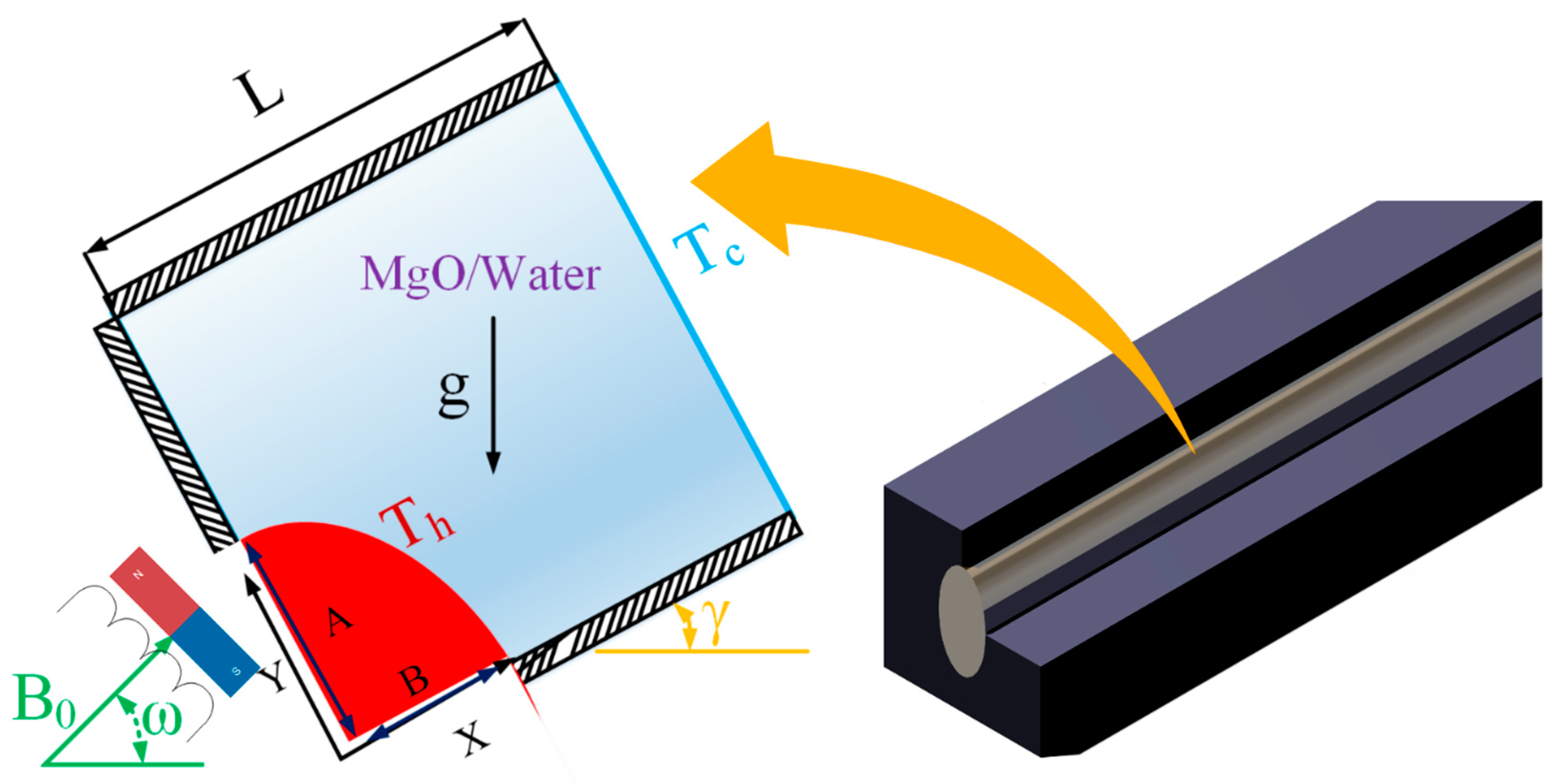
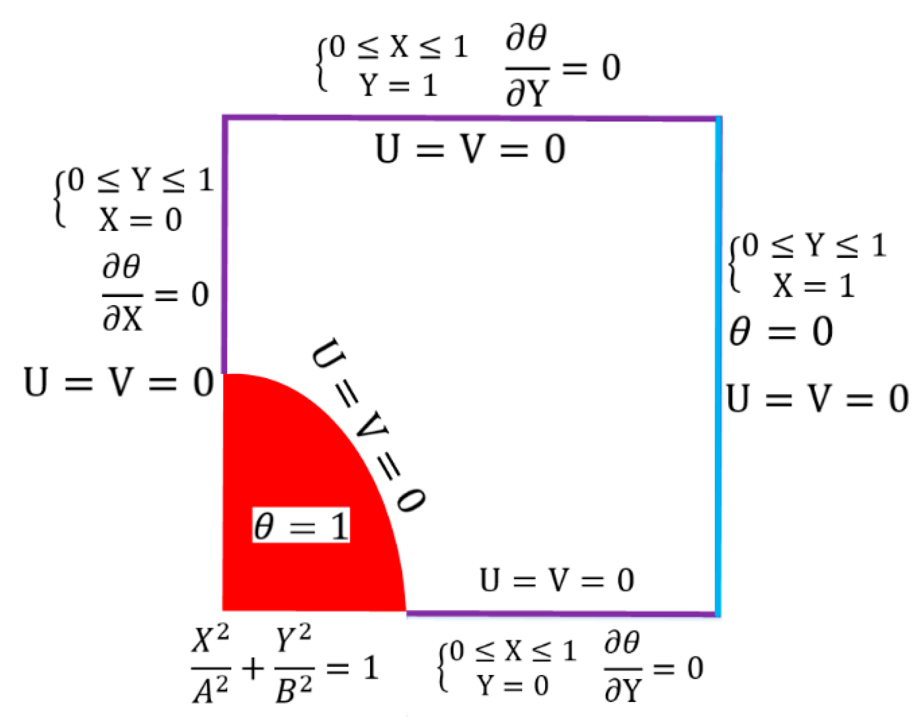
2. Problem Definition

A two and three-dimensional square enclosure, with dimensions L, contains MgO/water NFs. The enclosure has an angle of ω with the horizon. There is a blade with a temperature of T h at the bottom left edge of the enclosure. This blade is a part of the vertical ellipse. The right edge is at T c , while the left, upper, and lower edges are insulated. An MGF with an intensity of B 0 is applied to the enclosure. The MGF has an angle of γ with respect to the horizon. NCHT occurs inside the enclosure due to the temperature difference of the edges. The Boussinesq approximation is used to create the buoyancy force. Figure 1 illustrates the geometry of the desired enclosure.

2.1. Governing Equations

The main equations governing the fluid flow are written below [17,34], and they consider the following assumptions:
  • Laminar steady flow.
  • Incompressible and Newtonian Fluid.
  • No viscosity loss
  • Homogeneity of nanofluid and establishing the overall balance between nanoparticles and fluid
U X + V Y = 0
U U X + V U Y = P X + μ nf ρ nf α f ( 2 U X 2 + 2 U Y 2 ) + ρ f ρ nf σ nf σ f P r H a 2 ( Vsin ω cos ω Usin 2 ω ) + β nf β f R a P r θ sin γ
U V X + V V Y = P Y + μ nf ρ nf α f ( 2 V X 2 + 2 V Y 2 ) + ρ f ρ nf σ nf σ f P r H a 2 ( Usin ω cos ω Vcos 2 ω ) + β nf β f R a P r θ cos γ
( U θ X + V θ Y   ) = α nf α f ( 2 θ X 2 + 2 θ Y 2 ) + 4 3 k n f / k f ( ρ C P ) n f / ( ρ C P ) f ( k n f k f ) 1 R d 2 θ Y 2
S g e n = k n f k f ( ( θ X ) 2 + ( θ Y ) 2 ) + ζ { 2 [ ( U X ) 2 + ( V Y ) 2 ] + ( U Y + V X ) 2 } + ζ σ n f σ f μ f μ n f H a 2 ( U sin ω V cos ω ) 2
In Equation (4), Rd is defined as 4 T C 3 k f σ e β R , and the value ζ is expressed as μ n f T 0 k f ( α f L ( T h T C ) ) 2 in Equation (5). In addition, the definition of the dimensionless numbers of Rayleigh (Ra), Prandtl (Pr), Hartmann (Ha), Local Nusselt (NuY), and Bejan (Be) are as follows:
X ,   Y ,   A ,   B ,   L = x ,   y ,   a ,   b ,   l l ,   U ,   V = u ,   v   l α f , P = P ¯ l 2 ρ nf α f 2 ,   θ = T T c T h T c ,
r = ϑ f α f ,   R a = g β f l 3 ( T h T c ) α f ϑ f ,   H a = B 0 l σ f ρ f ϑ f ,   B e = S g e n , T S T o t a l ,   N u Y = h L k f + N u R d
By integrating on the surface of the enclosure, we can obtain the total entropy and the mean Be.
S t o t = S g e n d Ω = 0 1 S g e n d X d Y
B e A v e = 0 1 B e d X d Y
Using the dimensionless parameters and defining the local Nu, the average Nu that is derived by integrating on the cold edge from the local Nusselt is obtained by Relation (9):
N u = 1 L k n f k f 0 L ( θ X ) d Y
Figure 2 shows the problem’s boundary conditions without dimensions.

2.2. Relationships Related to NF Properties

In general, various relations can be used to express an NF’s thermal conductivity and viscosity. In this research, the relationships proposed by references [39] and [40] were used for the conductivity coefficient and the viscosity, respectively. The relation expressed by Esfe et al. [39] was obtained from laboratory data for magnesium oxide and water NFs. This relationship is applicable to the above-mentioned NFs and depends on various factors such as the NP volume percentage, temperature, and diameter. The relationship is as follows:
k n f k b f = 1.1507 + 0.05 φ 0.013 d p + 0.0038 T 0.0049 φ d p 0.0006 φ T 0.0019 d p T 0.0057 φ 2 0.0012 T 2 0.0013 φ d p T + 0.0013 φ 2 d p
Khodadadi et al. [40] proposed a relationship for the viscosity of magnesium oxide NFs that was derived from a laboratory study:
μ n f μ b f = 11.938 + 0.258 e φ 1.077 2.286 e T 0.266 + 0.679 T
Other NF properties can be calculated from the following equations.
σ n f = ( 1 φ ) σ f + φ σ p
ρ nf = ( 1 φ ) ρ f + φ ρ p
( ρ β ) nf = ( 1 φ ) ( ρ β ) f + φ ( ρ β ) p
( ρ c p ) nf = ( 1 φ ) ( ρ c p ) f + φ ( ρ c p ) p
α nf = k nf ( ρ c p ) nf
Table 1 presents different thermophysical properties for magnesium oxide and water NPs.

2.3. Numerical Methods

Equations (1)–(5) are the main equations governing fluid flow that should be solved by software to obtain the desired results. Figure 2 provides the boundary conditions required for this purpose. In this regard, a SIMPLE code written in FORTRAN software was used to simultaneously solve the equations and obtain the results for writing algebraic equations of volume control. In addition, the convergence criterion was used as follows:
Φ = J I | φ n + 1 φ n φ n + 1 | 10 8
For the numerical solution, it is first necessary to have a mesh geometry, for which we used a regular square mesh, as shown in Figure 3 for a 2D enclosure.

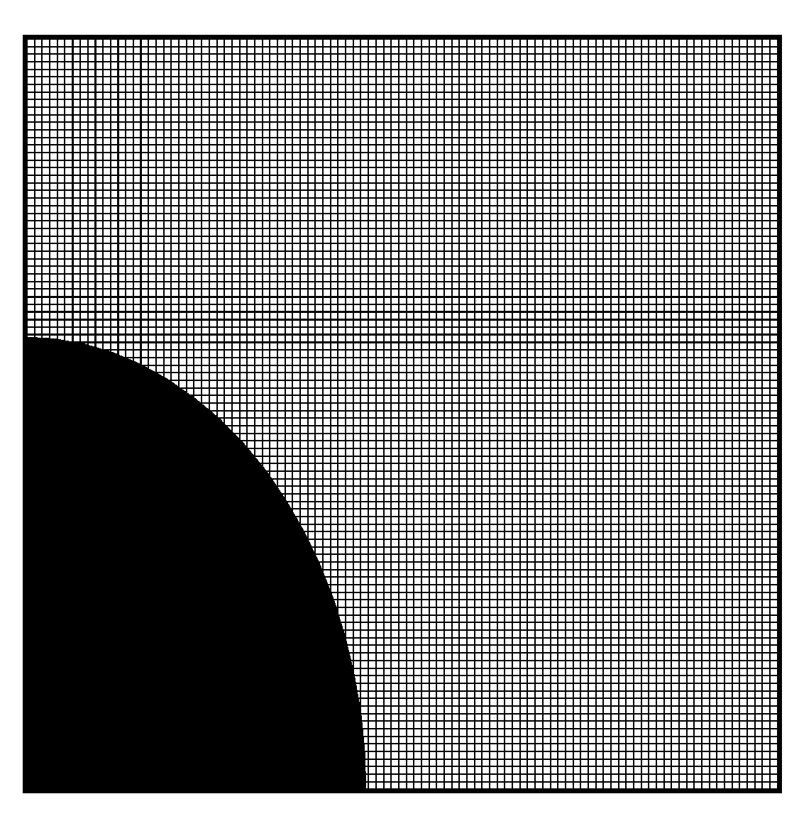
3. Validating and Evaluating the Grid-Independent Solution

The results of this research were compared to those of previous works to verify the validity of the results obtained from the written code. We used two studies to ensure the validity of the results. Table 2 compares the values of mean Nu with the results of Aminossadati and Ghasemi’s [43] research for the NCHT inside a square enclosure. The bottom edge of this enclosure (which is heated from below) and the vertical edges have low temperatures (cold). According to Table 2, the values of Nu are close to each other for both works.
Table 3 reports the next comparison performed between the amounts of entropy generated in a square enclosure derived from this paper and [44] at different RAP values of the enclosure. Accordingly, a slight difference was observed between the results of this work and the desired article.
Then, reviews were performed to evaluate the effect of the number of grid points on the results of the solution. Table 4 represents an example of these reviews for H a = 20 ,   A R = 0.45 0.6 ,   γ = 45 ,   ω = 0 ,   φ = 0.03 ,   Rd = 1 , and Ra = 10 5 . Based on the results, it is obvious that the solutions remained almost the same for grids smaller than 120 × 120. Thus, we selected a uniform 120 × 120 grid for running programs.

4. Results and Discussion

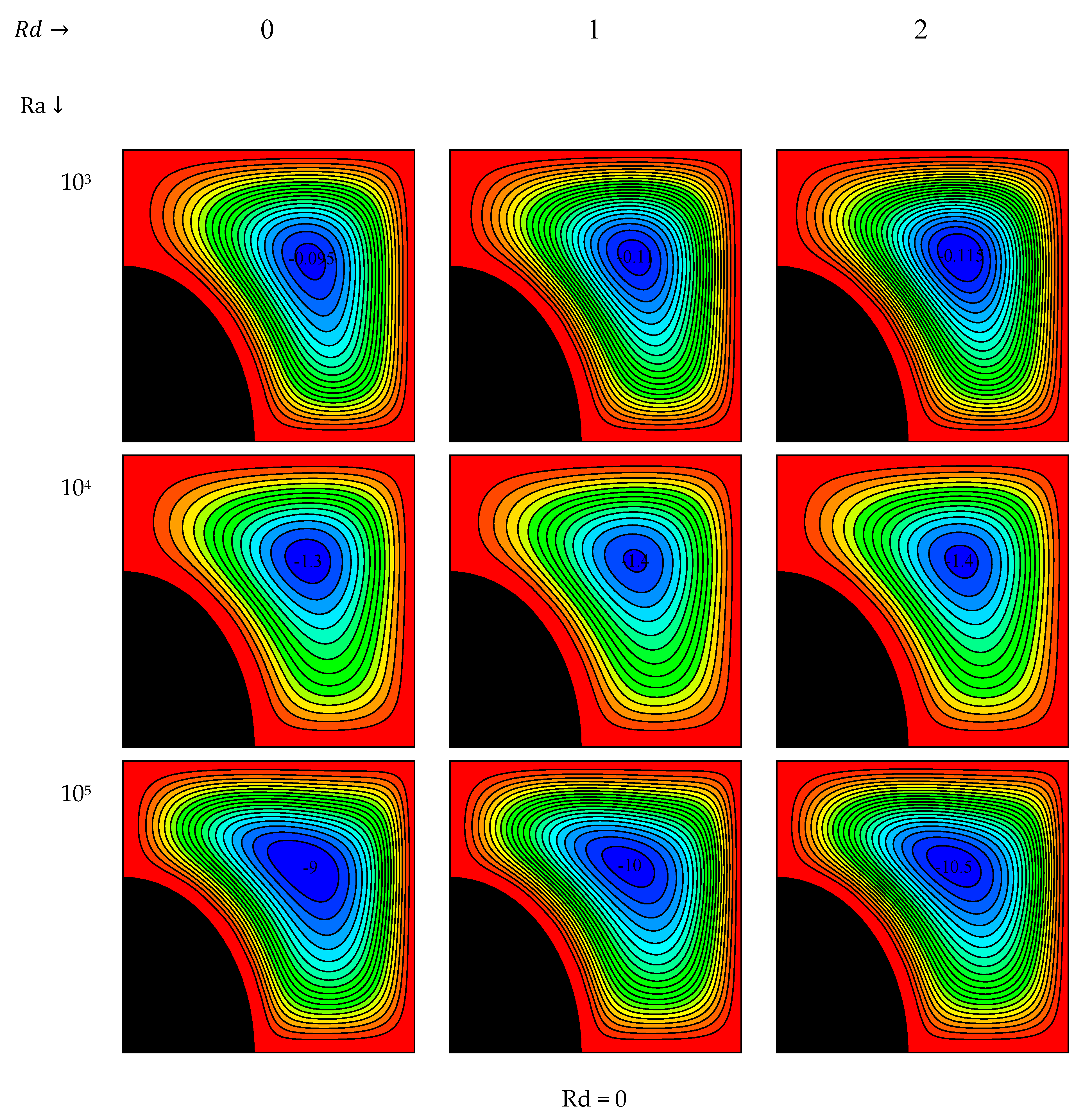
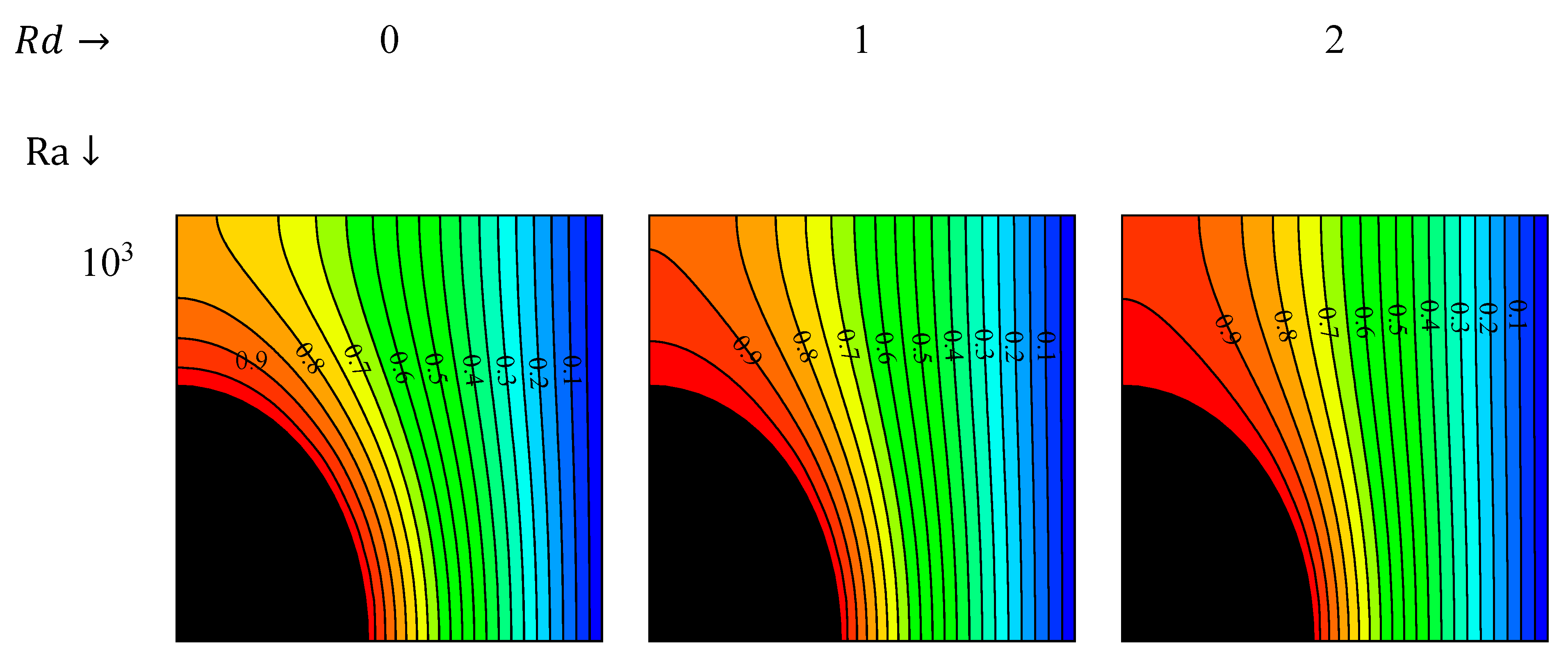
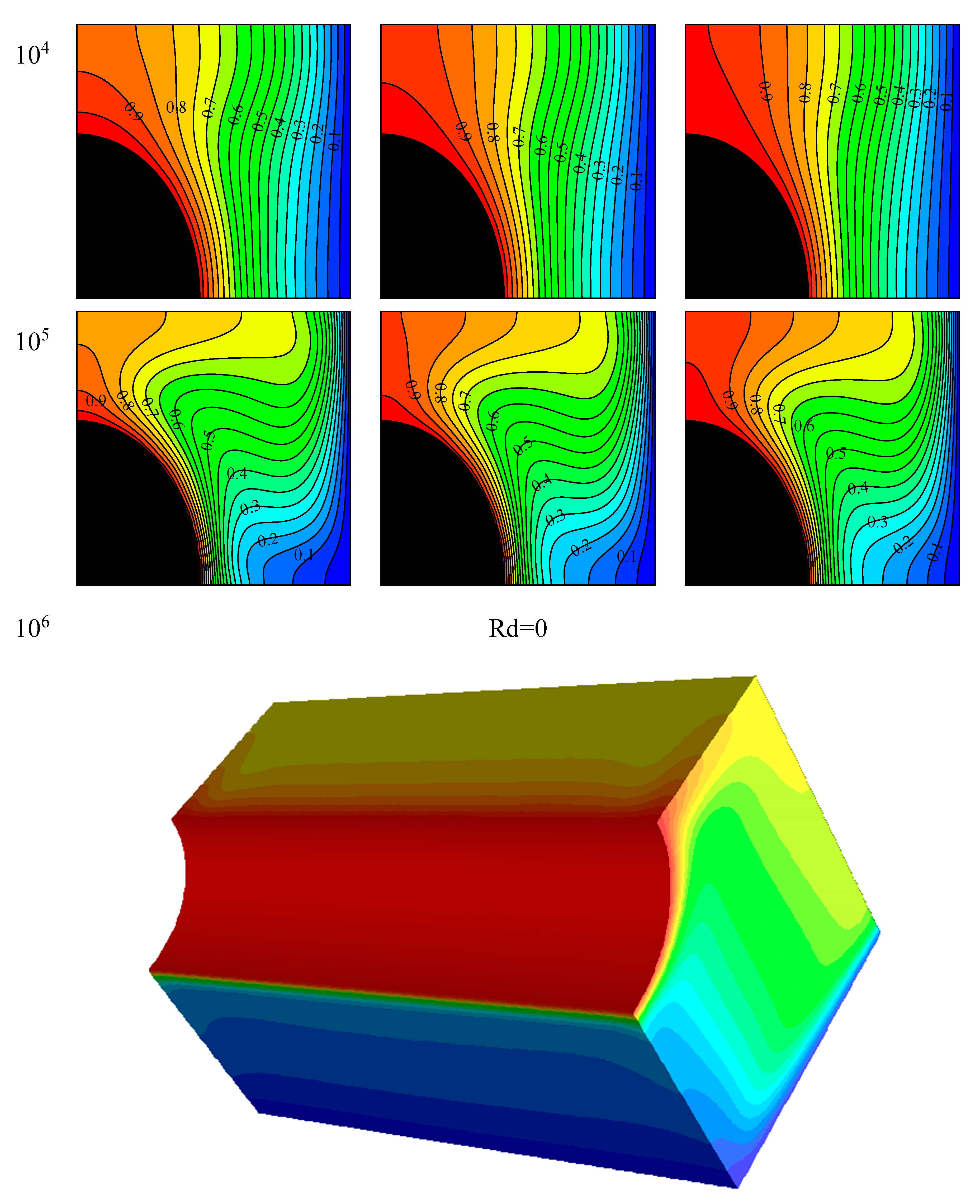
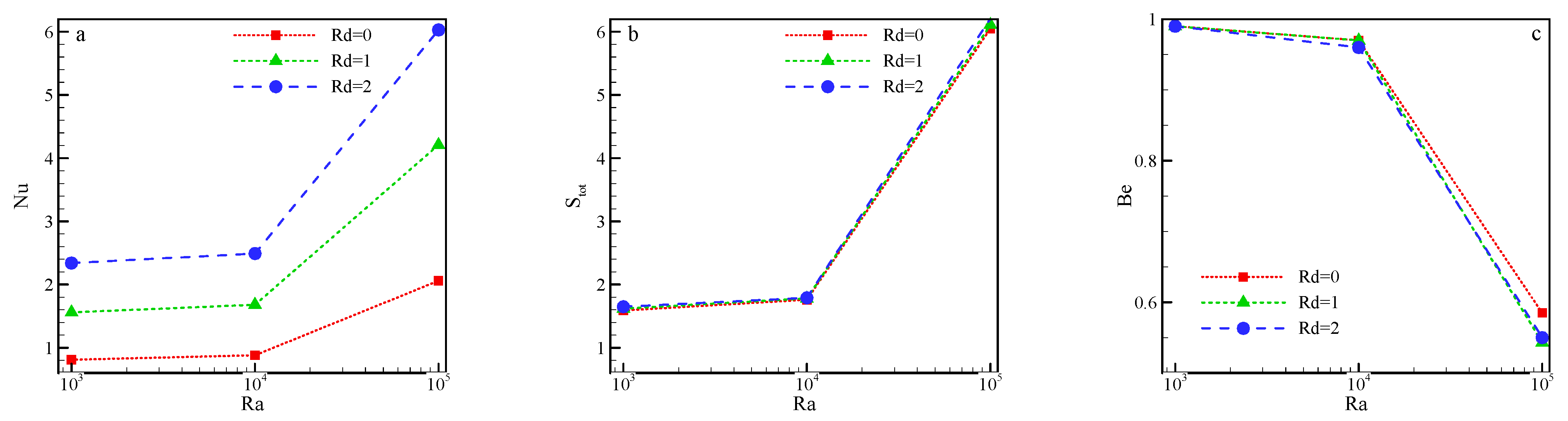
4.1. Changes in RAP and Ra
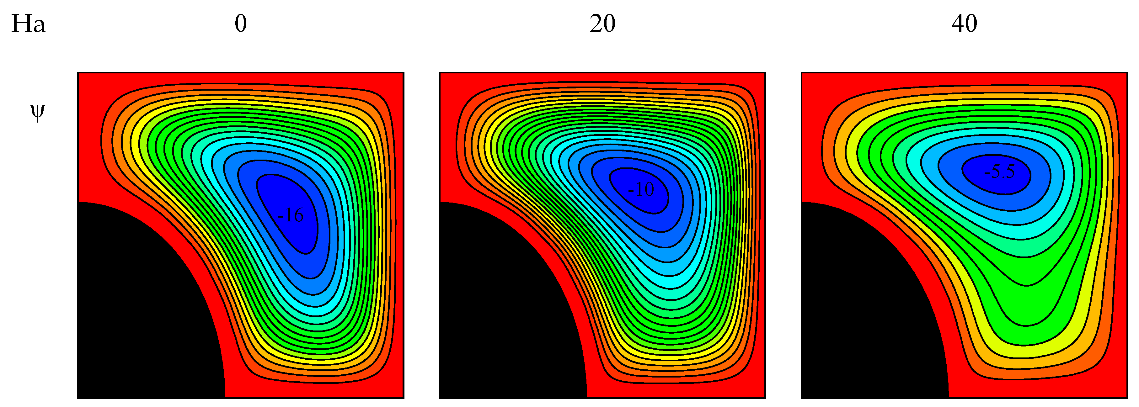
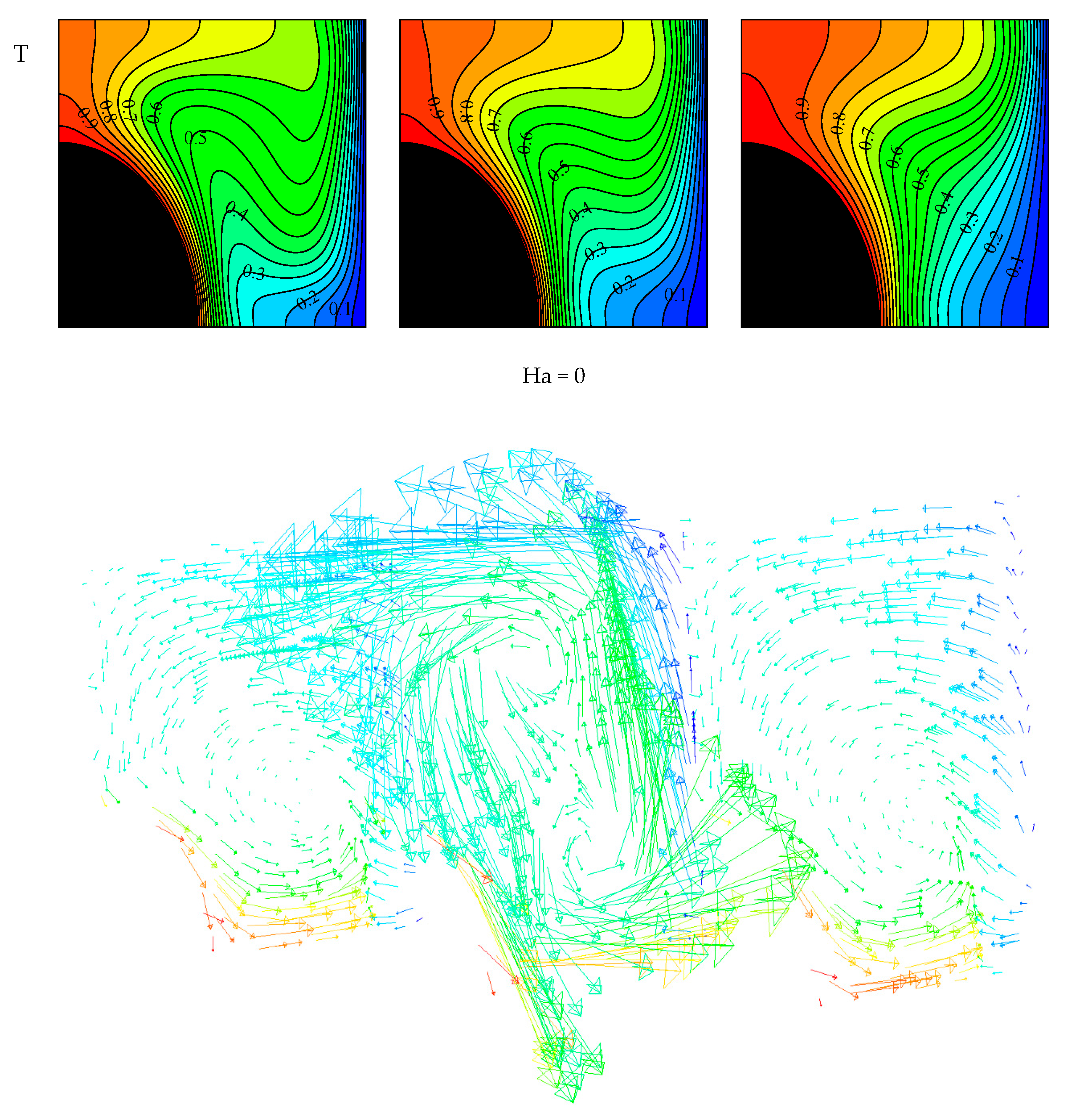
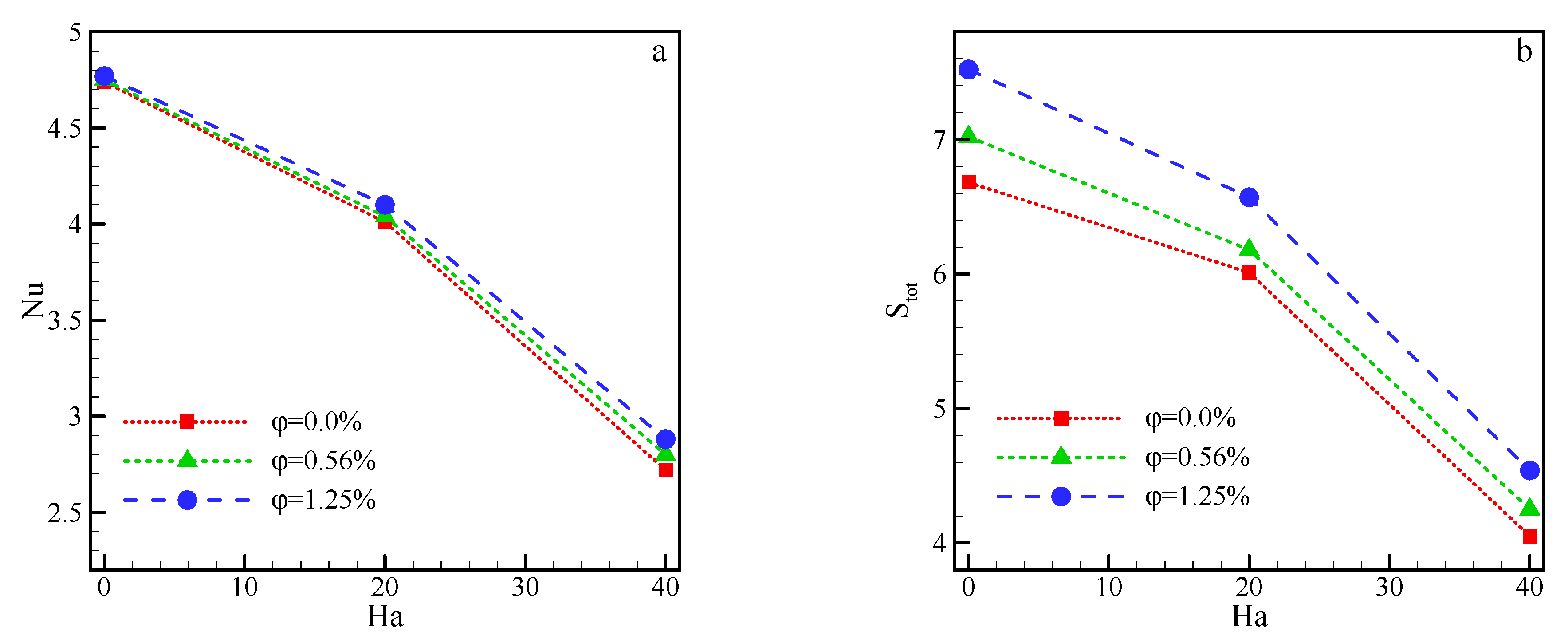
Figure 4 demonstrates the speed contours for the above-mentioned values. As observed, positive changes in the strength of the flow field were made by increasing the Ra and RAP values, although the magnitude of the increase in the flow field was significantly higher than that of the RAP due to the high dependency of the flow field on the Ra. Nevertheless, changing the level of radiation failed to significantly affect the field strength. On the other hand, the Ra and the flow field were strongly dependent on each other, and any changes in the Ra changed the field strength. Therefore, the strongest vortex occurred at Ra 10 6 and the RAP value of 2. Ultimately, an augmentation of the Ra increased the buoyancy force, resulting in a stronger vortex and flow function.
Figure 5 depicts the temperature contours for the above-mentioned values. Concerning the isotherm lines, it was observed that changing both parameters of Ra and RAP affected the isotherm parameter and changed the lines. Compared to the RAP, changing the Ra significantly affects the temperature field due to its greater disruption of the fluid. Though this process was found to disrupt the isothermal lines, it also had a great effect on them. The variation of RAP, which has a heat transfer mechanism and therefore did not impose great effects on the isothermal lines affected by the flow field, increased the radiation heat transfer. In this way, increasing the Ra increased the strength of the flow field, highly disrupted the fluid inside the enclosure, and led to irregular isothermal lines that were regular and flat with the low Ra values.
Figure 6 shows the diagrams of the mean Nu, generated entropy, and Be for the stated values. As shown, an augmentation of the Ra and RAP increased the average Nu. It is worth noting that the increase caused by the Ra was due to the increase in the NCHT, while the increased Nu resulted was due to the increase in the radiation heat transfer. Furthermore, increasing the Ra caused fluid disruption in the enclosure and increased the temperature gradient near the edge and blade, resulting in an increasing HTR. On the other hand, an augmentation of the RAP raised the HTR by amplifying the radiation heat transfer. The changes in EGE and Nu depended on similar factors such as velocity and temperature variation, and augmentations of the Ra, velocity, and temperature increased the total generated entropy. As shown in the Be diagram, increasing the Ra reduced the Be value, while the RAP failed to significantly affect this value. Be is the ratio of thermal entropy to the total generated entropy. The results also indicated that an augmentation of the Ra increased the total generated entropy and reduced the Be. However, changing the RAP had no significant effect on the EGE and, subsequently, the Be.

4.2. Ha Variation

Figure 7 illustrates the velocity and temperature contours for the above-mentioned values. As shown, increasing the Ha reduced the strength of fluid displacement in the enclosure. Furthermore, decreasing the NCHT in the enclosure decreased the velocity of the vortices. It should be noted that the reduction in the flow contours was observed in the form of a decreased value of flow function. In general, it can be said that the stronger the MGF, the higher the resulting force, which is called Lorentz force and is applied to the MGF. In isothermal field lines, an augmentation of the Ha decreased the congestion in the upper and lower regions of the enclosure. Accordingly, increasing the force from the MGF decreased the fluid velocity and thus reduced the temperature difference in the enclosure, which was seen as a reduction in the congestion of isotherm lines.
Figure 8 provides the mean Nu and EGE for constant and variable values. Considering the diagram of the Nu and EGE, it can be seen that an augmentation of the Ha decreased these two values. On the other hand, an augmentation of the strength of MGF was interpreted increasing Lorentz force in the enclosure, resulting in a reduction of the velocity of the fluid in the enclosure in the first phase and a decrease of the temperature difference along the constant-temperature edges in the second phase due to the decrease in fluid velocity. Given the dependence of entropy on temperature difference and velocity, an augmentation of the Ha reduced the amount of EGE. Though entropy depends on the MGF, the dependent parameter is much smaller than that of the two entropies that dependent on the temperature difference and velocity. Both graphs indicate the changes in terms of the volume percentage of NPs. In this case, both graphs show an ascending trend with increasing NPs in water. The addition of NPs increased the thermal conductivity of the fluid and ultimately increased HTR and EGE.

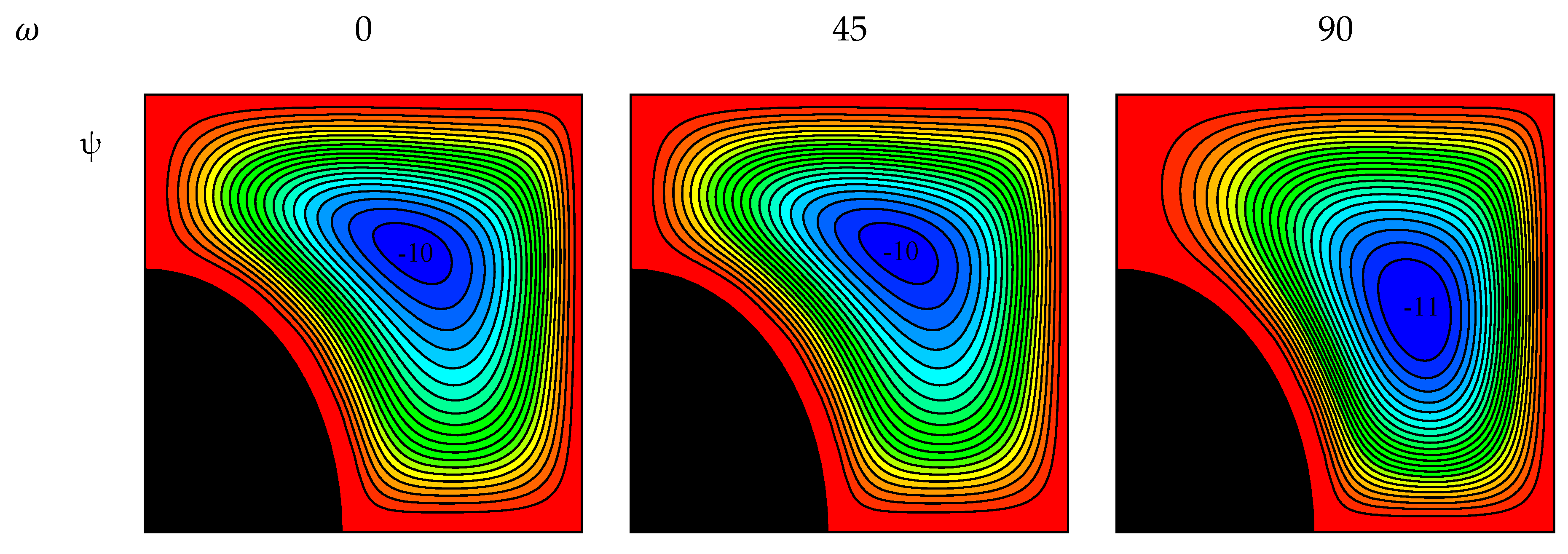
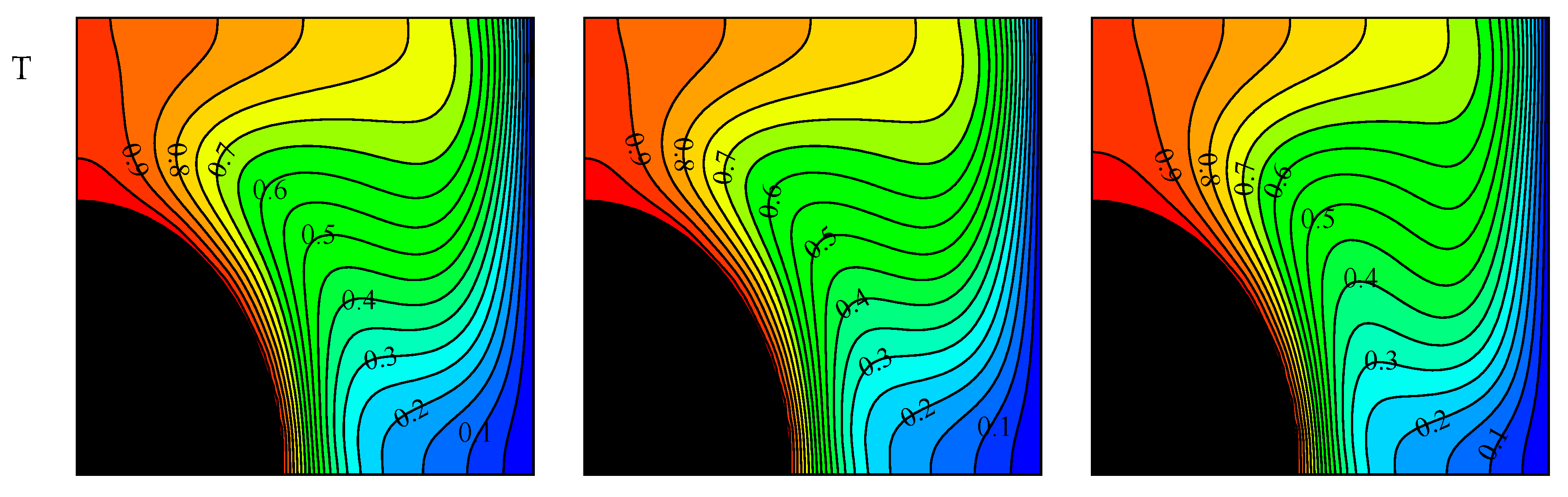
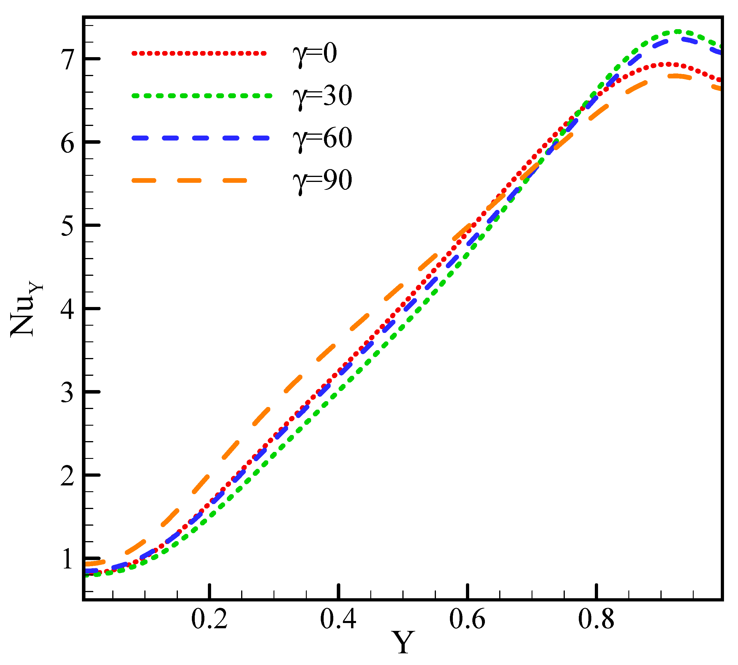
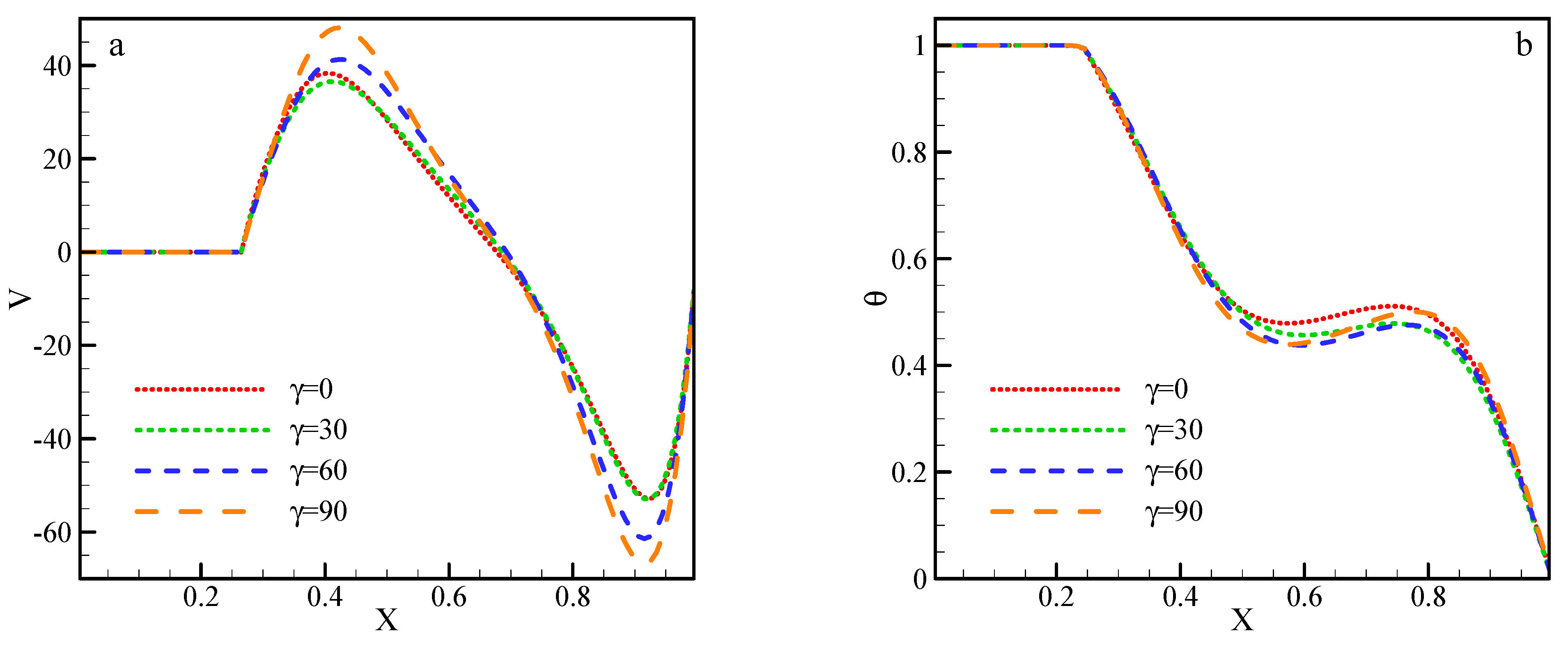
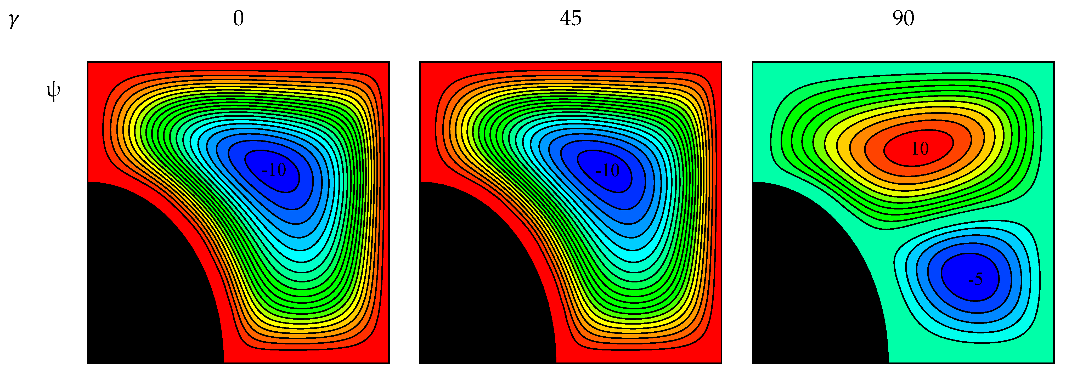
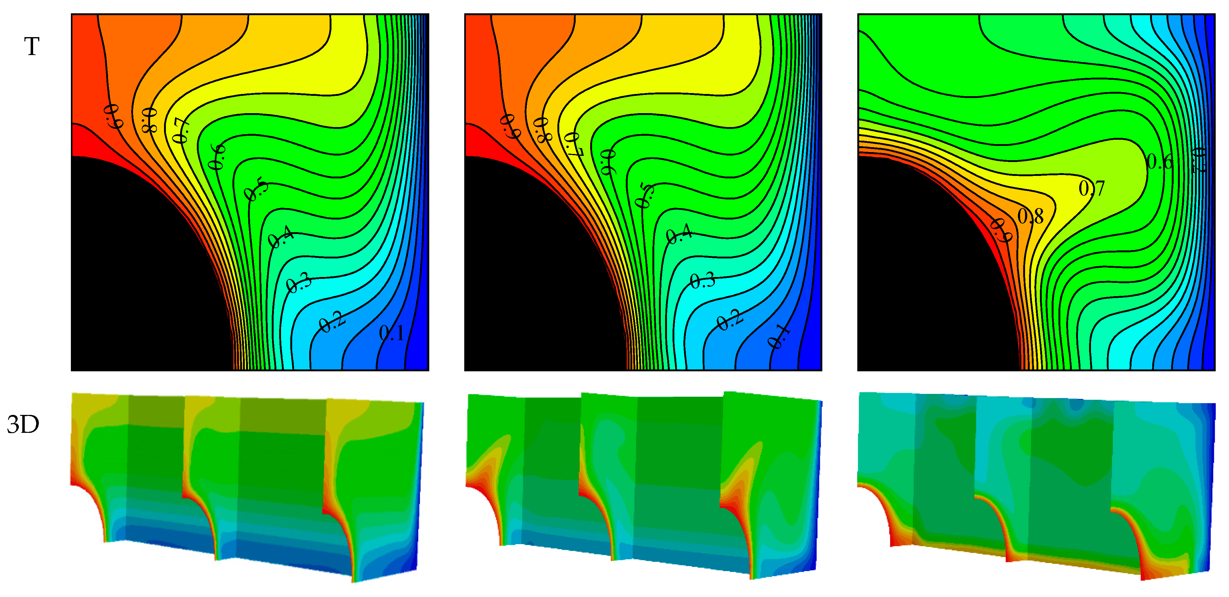
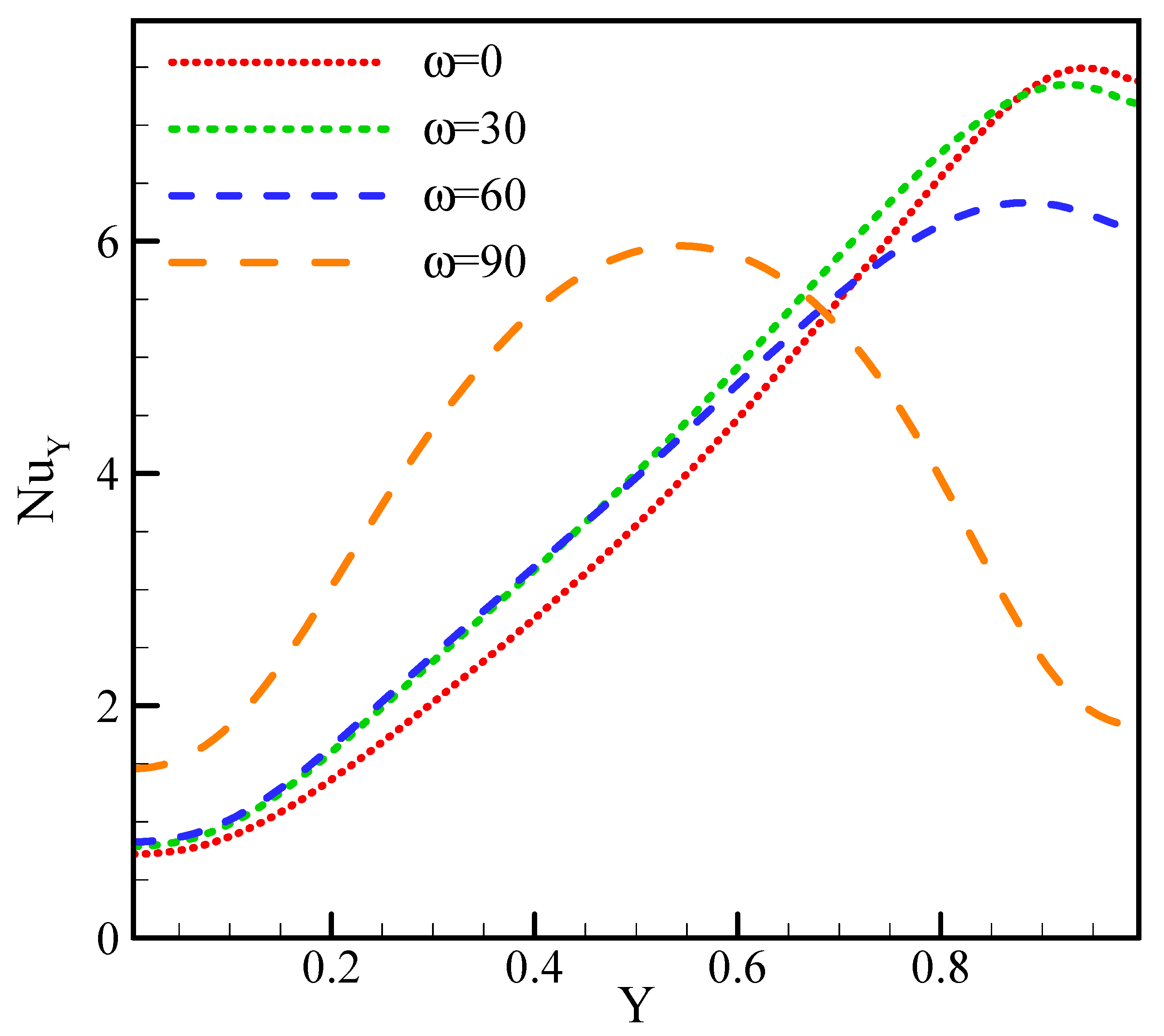
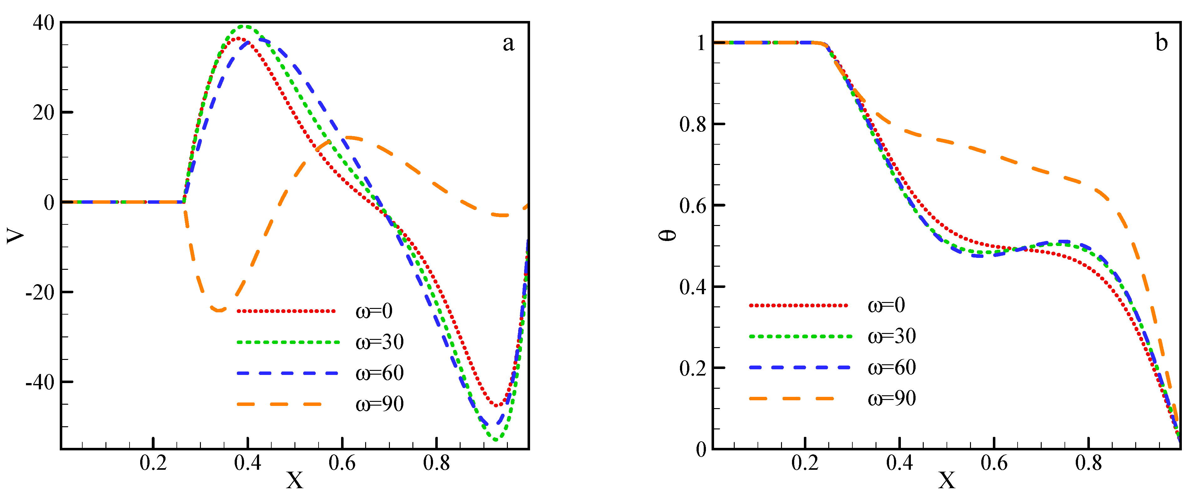
4.3. Changes in the MGF Angle

Figure 9 displays the velocity and temperature contours for the above-mentioned values. Changes in the angle of the MGF changed the angle of the magnetic force, which may have affected the vortex strength and caused changes in the number of vortices, their direction, and strength. Hence, the amount of the flow function was increased at the center of the vortex more than in its previous state by increasing the angle of the MGF from 0 to 90 degrees. Regarding the isothermal field lines, changing the angle of the MGF highlighted variations in their curvature, and changing the angle of the enclosure caused changes in the curvature of the isotherms. Additionally, increasing the velocity of the fluid flow in the enclosure led to fluid disruption, resulting in an increase of the curvature of the lines in the isothermal field.
Figure 10 shows the local Nu on the cold edges for the above-mentioned values. According to the local Nu, increasing the angle of the MGF increased the HTR in the lower part of the edge and decreased its value near the edge due to the collision of hot fluid in the cold edge. In the horizontal MGF mode, the highest impact of hot fluid collision occurred in the upper part of the edge, which created heat transfer in this place that was greater than that of any other case. It can be stated that increasing the angle of the MGF to 90 degrees increased the amount of HTR in the middle of the edge and reduced the amount of HTR above the enclosure.
Figure 11 shows vertical velocity and dimensionless temperature diagrams plotted in the middle horizontal line of the enclosure. In the vertical velocity diagram, an augmentation of the MGF angle increased the velocity of the enclosure to its maximum level. In this case, a stronger vortex was created in the enclosure due to its better conditions. The temperature diagram shows that changing the angle of the MGF led to a slight change in the dimensional temperature in the middle of the enclosure. Since no specific change was observed in the temperature at the side of the edges, the temperature was 1 at the beginning of the edge. There was a blade in this region of which the dimensionless temperature was 1, a value that decreased as the blade approached the temperature of the cold edge.

4.4. Changes in Enclosure Angle

Figure 12 provides the velocity and temperature contours for the above-mentioned values. Changing the angle of the enclosure essentially changed the angle of the gravitational acceleration in the momentum equation. Since the NCHT depends on the angle of the gravitational acceleration, any change in the angle of the enclosure affected this acceleration. The direction of the buoyancy force was in line with the gravitational force and opposite to its direction. Hence, changing the angle of the enclosure significantly affected the angle of the buoyancy force, such that an augmentation of the enclosure angle increased the number of vortices from one to two in the field of flow lines. As shown in temperature field, increasing the angle of the enclosure increased the curvature of the isotherm lines in the middle of the enclosure due to the increased number of vortices from one to two; this resulted in a greater degree of fluid disruption in the middle of the enclosure and at the collision area of the two vortices.
Figure 13 illustrates the values of the local Nu on the cold edge of the enclosure for the above-mentioned values. The enclosure’s angle variation, especially at high angles, significantly affected the heat transfer from the cold edge, such that verticalizing the enclosure replaced the area with the most heat transfer. The vertical enclosure of the fluid collided with the cold edge in the middle of the fluid hot edge, but this issue mostly occurred at the upper part of the edge. Therefore, in the vertical enclosure, the highest HTR was observed in the middle of the edge, although the highest Nu could be found at the bottom of the edge.
Figure 14 shows vertical velocity and dimensionless temperature diagrams, which are plotted on the horizontal middle line of the enclosure for high values. It can be observed that changes in the enclosure angle considerably affected the vertical velocity in the enclosure, such that verticalizing the enclosure changed the extremums of the velocity. After increasing the angle of the enclosure, it was observed that there was a relative increase in the velocity values. However, verticalizing the enclosure led to various changes in the enclosure and the formation of two vortices. Considering the temperature diagram, the temperature variations were low in the variation range of the enclosure angle from 0 to 60 °C. However, verticalizing the enclosure led to more changes in the dimensionless temperature and generally changed the temperature profile due to the changes in the number and strength of the vortices because of the changed angle of the enclosure.

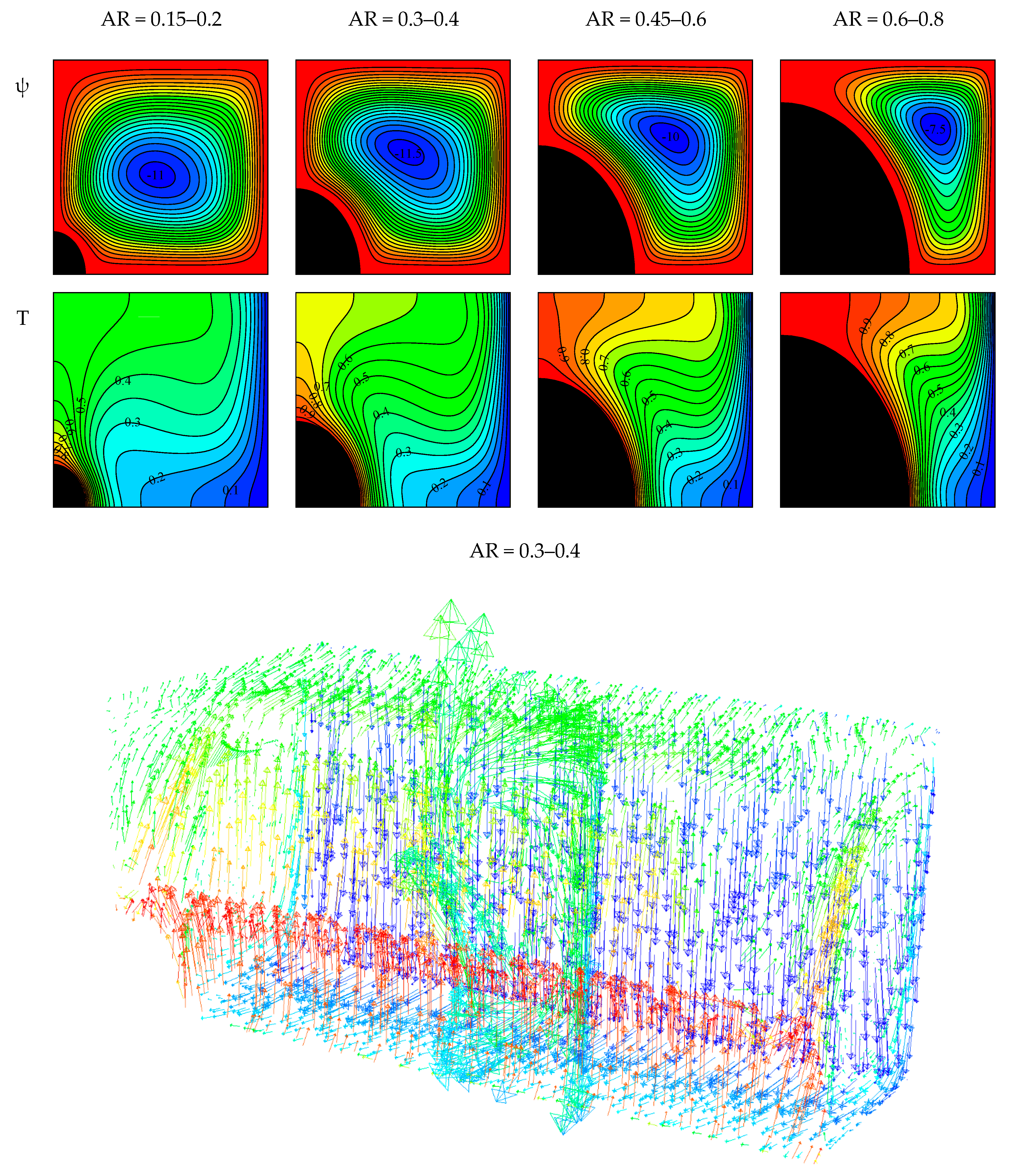
4.5. Changes in Aspect Ratio

Figure 15 provides the velocity and temperature contours for the above-mentioned values. As shown, increasing the size of the hot blade imposed various effects on the temperature and flow fields. Blade enlargement both increased the level of heat exchange between the fluid and the heated edge and reduced the volume of the enclosure for fluid flow. On the other hand, an augmentation of the level of heat exchange caused the fluid to be warm along a greater length of the blade, resulting in a warmer fluid. Furthermore, reducing the space in the enclosure caused the fluid to have less chance for displacement and decreased its velocity. In the flow field, it was first observed that the enlargement of the blade increased the flow function, although it decreased afterward. Consequently, blade enlargement in the temperature field reduced the arc of the isotherm lines and, in turn, increased their congestion along the constant temperature edges, especially the cold edge.
In general, an augmentation of the size of the blade first increased and then decreased the HTR. First, the enlargement of the blade due to the increased heat exchange between the blade and the fluid ultimately increased the Nu. However, the excessive increase of the blade reduced the space inside the enclosure, resulting in a sharp decline in the fluid velocity, a decreased displacement, and a reduced HTR. The entropy changes depend on the values of velocity and temperature, and an augmentation of the size of the blade increased the congestion of the isotherm lines near the constant temperature edges. Despite the initial increase, a decreasing trend was observed in the values of velocity, which increased the entropy of heat transfer and reduced the entropy of fluid loss. Based on the results, the entropy first increased and then the enlargement of the blade decreased it, which was a similar trend to that of the Nu. It is noteworthy that an increasing trend was always observed in the changes of the Be due to the blade enlargement. The reason for this trend was the increase in thermal entropy by enlarging the blade, which caused the values of the Be to follow an ascending trend (Table 5).

5. Conclusions

By using MgO/water NFs, the authors of this study sought to evaluate NCHT with volumetric radiation and EGE in a two and three-dimensional square enclosure. The enclosure was subjected to an MGF with different angles, and the enclosure had its own different angles. A hot elliptic blade was located in the corner of the enclosure. The most important results of this research are as follows:
First, increasing the Ra and RAP increased the Nu. Furthermore, an augmentation of the Ra increased the entropy and decreased the Be.
Second, increasing the Ha decreased the Nu and EGE.
Third, adding NPs to the base fluid would increase HTR and EGE in the enclosure.
Fourth, an augmentation of the MGF angle from 0 to 90 degrees could increase the maximum value of the flow function in the flow contour.
Finally, increasing the elliptically shaped blade’s aspect ratio increased the Nu and entropy in the enclosure. However, a further increase in the aspect ratio was able to significantly decrease both of these values. In this case, increasing the aspect ratio always increased the Be.

Author Contributions

Conceptualization, Y.K.; Data curation, Y.K. and A.A.A.; Formal analysis, Y.K., A.T. and A.A.A.; Investigation, Y.K., A.A.A., A.T. and A.A.; Methodology, Y.K., A.A.A. and A.A.; Supervision, Y.K., M.S. and G.C.; Writing—original draft, Y.K., A.A.A., A.A. and A.T.; Writing—review & editing, A.A., M.S. and G.C. All authors have read and agreed to the published version of the manuscript.

Funding

This research received no external funding.

Institutional Review Board Statement

Not applicable.

Informed Consent Statement

Not applicable.

Data Availability Statement

Not applicable.

Acknowledgments

This work was supported by the Taif University Researchers Supporting Project, Taif University, Taif, Saudi Arabia, under Project TURSP-2020/121.

Conflicts of Interest

The authors declare no conflict of interest.

Abbreviations

Nomenclatures
aBigger diameter fin
ANon-dimensional bigger diameter fin
ARAspect ratio
bSmaller diameter fin
BNon-dimensional smaller diameter fin
B0Magnetic field strength
C p Specific heat at constant pressure
gGravity
H a Hartmann number
kThermal conductivity
lNon-dimensional enclosure height
LEnclosure height
N u Nusselt number
P Pressure
P r Prandtl number
R a Rayleigh number
R d Radiation parameter
SEntropy
T Temperature
u ,   v Velocity in the x and y directions
x , y Cartesian coordinates
Greek letters
ωangel of magnetic field (MGF)
σ The electrical conductivity
φsolid volume fraction
ψ Stream function value
α Thermal diffusivity
ρ Density
μ Dynamic viscosity
γ angel of cavity
Subscripts
C Cold
f fluid
H Hot
l m Average
n f Nanofluid (NF)
p Nanoparticle (NP)
totTotal

References

  1. Ahmadi, M.H.; Mohseni-Gharyehsafa, B.; Ghazvini, M.; Goodarzi, M.; Jilte, R.D.; Kumar, R. Comparing various machine learning approaches in modeling the dynamic viscosity of CuO/water nanofluid. J. Therm. Anal. Calorim. 2020, 139, 2585–2599. [Google Scholar] [CrossRef]
  2. Aghakhani, S.; Pordanjani, A.H.; Karimipour, A.; Abdollahi, A.; Afrand, M. Numerical investigation of heat transfer in a power-law non-Newtonian fluid in a C-Shaped cavity with magnetic field effect using finite difference lattice Boltzmann method. Comput. Fluids 2018, 176, 51–67. [Google Scholar] [CrossRef]
  3. Li, Z.; Sarafraz, M.M.; Mazinani, A.; Hayat, T.; Alsulami, H.; Goodarzi, M. Pool boiling heat transfer to CuO-H2O nanofluid on finned surfaces. Int. J. Heat Mass Transf. 2020, 156, 119780. [Google Scholar] [CrossRef]
  4. Bahiraei, M.; Jamshidmofid, M.; Goodarzi, M. Efficacy of a hybrid nanofluid in a new microchannel heat sink equipped with both secondary channels and ribs. J. Mol. Liq. 2019, 273, 88–98. [Google Scholar] [CrossRef]
  5. Shadloo, M.S. Application of support vector machines for accurate prediction of convection heat transfer coefficient of nanofluids through circular pipes. Int. J. Numer. Methods Heat Fluid Flow 2020. [Google Scholar] [CrossRef]
  6. Ahmadi, A.A.; Arabbeiki, M.; Ali, H.M.; Goodarzi, M.; Safaei, M.R. Configuration and Optimization of a Minichannel Using Water–Alumina Nanofluid by Non-Dominated Sorting Genetic Algorithm and Response Surface Method. Nanomaterials 2020, 10, 901. [Google Scholar] [CrossRef] [PubMed]
  7. Shadloo, M.S. Numerical simulation of compressible flows by lattice Boltzmann method. Numer. Heat Transf. Part A Appl. 2019, 75, 167–182. [Google Scholar] [CrossRef]
  8. Maleki, A.; Elahi, M.; Assad, M.E.H.; Nazari, M.A.; Shadloo, M.S.; Nabipour, N. Thermal conductivity modeling of nanofluids with ZnO particles by using approaches based on artificial neural network and MARS. J. Therm. Anal. Calorim. 2021, 143, 4261–4272. [Google Scholar] [CrossRef]
  9. Sadeghi, R.; Shadloo, M.S.; Hooman, K. Numerical investigation of the natural convection film boiling around elliptical tubes. Numer. Heat Transf. Part A Appl. 2016, 70, 707–722. [Google Scholar] [CrossRef]
  10. Peng, Y.; Parsian, A.; Khodadadi, H.; Akbari, M.; Ghani, K.; Goodarzi, M.; Bach, Q.-V. Develop optimal network topology of artificial neural network (AONN) to predict the hybrid nanofluids thermal conductivity according to the empirical data of Al2O3—Cu nanoparticles dispersed in ethylene glycol. Phys. A Stat. Mech. Appl. 2020, 549, 124015. [Google Scholar] [CrossRef]
  11. Wang, N.; Maleki, A.; Nazari, M.A.; Tlili, I.; Shadloo, M.S. Thermal Conductivity Modeling of Nanofluids Contain MgO Particles by Employing Different Approaches. Symmetry 2020, 12, 206. [Google Scholar] [CrossRef] [Green Version]
  12. Selimefendigil, F.; Öztop, H.F. Corrugated conductive partition effects on MHD free convection of CNT-water nanofluid in a cavity. Int. J. Heat Mass Transf. 2019, 129, 265–277. [Google Scholar] [CrossRef]
  13. Sheikholeslami, M.; Seyednezhad, M. Simulation of nanofluid flow and natural convection in a porous media under the influence of electric field using CVFEM. Int. J. Heat Mass Transf. 2018, 120, 772–781. [Google Scholar] [CrossRef]
  14. Miroshnichenko, I.V.; Sheremet, M.A.; Oztop, H.F.; Abu-Hamdeh, N. Natural convection of Al2O3/H2O nanofluid in an open inclined cavity with a heat-generating element. Int. J. Heat Mass Transf. 2018, 126, 184–191. [Google Scholar] [CrossRef]
  15. Pordanjani, A.H.; Aghakhani, S.; Afrand, M.; Mahmoudi, B.; Mahian, O.; Wongwises, S. An updated review on application of nanofluids in heat exchangers for saving energy. Energy Convers. Manag. 2019, 198, 111886. [Google Scholar] [CrossRef]
  16. Miroshnichenko, I.V.; Sheremet, M.A.; Oztop, H.F.; Abu-Hamdeh, N. Natural convection of alumina-water nanofluid in an open cavity having multiple porous layers. Int. J. Heat Mass Transf. 2018, 125, 648–657. [Google Scholar] [CrossRef]
  17. Pordanjani, A.H.; Jahanbakhshi, A.; Nadooshan, A.A.; Afrand, M. Effect of two isothermal obstacles on the natural convection of nanofluid in the presence of magnetic field inside an enclosure with sinusoidal wall temperature distribution. Int. J. Heat Mass Transf. 2018, 121, 565–578. [Google Scholar] [CrossRef]
  18. Aghakhani, S.; Ghasemi, B.; Pordanjani, A.H.; Wongwises, S.; Afrand, M. Effect of replacing nanofluid instead of water on heat transfer in a channel with extended surfaces under a magnetic field. Int. J. Numer. Methods Heat Fluid Flow 2019, 29, 1249–1271. [Google Scholar] [CrossRef]
  19. Dogonchi, A.; Selimefendigil, F.; Ganji, D. Magneto-hydrodynamic natural convection of CuO-water nanofluid in complex shaped enclosure considering various nanoparticle shapes. Int. J. Numer. Methods Heat Fluid Flow 2018, 29, 1663–1679. [Google Scholar] [CrossRef]
  20. Armaghani, T.; Kasaeipoor, A.; Izadi, M.; Pop, I. MHD natural convection and entropy analysis of a nanofluid inside T-shaped baffled enclosure. Int. J. Numer. Methods Heat Fluid Flow 2018, 28, 2916–2941. [Google Scholar] [CrossRef]
  21. Abbassi, M.A.; Orfi, J. Effects of Magnetohydrodynamics on Natural Convection and Entropy Generation with Nanofluids. J. Thermophys. Heat Transf. 2018, 32, 1059–1071. [Google Scholar] [CrossRef]
  22. Ghasemi, K.; Siavashi, M. MHD nanofluid free convection and entropy generation in porous enclosures with different conductivity ratios. J. Magn. Magn. Mater. 2017, 442, 474–490. [Google Scholar] [CrossRef]
  23. Yan, S.-R.; Aghakhani, S.; Karimipour, A. Influence of a membrane on nanofluid heat transfer and irreversibilities inside a cavity with two constant-temperature semicircular sources on the lower wall: Applicable to solar collectors. Phys. Scr. 2020, 95, 085702. [Google Scholar] [CrossRef]
  24. Ghasemi, B.; Aminossadati, S.; Raisi, A. Magnetic field effect on natural convection in a nanofluid-filled square enclosure. Int. J. Therm. Sci. 2011, 50, 1748–1756. [Google Scholar] [CrossRef]
  25. Pordanjani, A.H.; Aghakhani, S. Numerical Investigation of Natural Convection and Irreversibilities between Two Inclined Concentric Cylinders in Presence of Uniform Magnetic Field and Radiation. Heat Transf. Eng. 2021, 1–21. [Google Scholar] [CrossRef]
  26. Nia, M.F.; Nassab, S.A.G.; Ansari, A.B. Transient combined natural convection and radiation in a double space cavity with conducting walls. Int. J. Therm. Sci. 2018, 128, 94–104. [Google Scholar] [CrossRef]
  27. Ridouane, E.H.; Hasnaoui, M.; Campo, A. Effects of surface radiation on natural convection in a rayleigh-benard square enclosure: Steady and unsteady conditions. Heat Mass Transf. 2006, 42, 214. [Google Scholar] [CrossRef]
  28. Tian, M.-W.; Rostami, S.; Aghakhani, S.; Goldanlou, A.S.; Qi, C. A techno-economic investigation of 2D and 3D configurations of fins and their effects on heat sink efficiency of MHD hybrid nanofluid with slip and non-slip flow. Int. J. Mech. Sci. 2021, 189, 105975. [Google Scholar] [CrossRef]
  29. Ramesh, N.; Venkateshan, S. Effect of surface radiation and partition resistance on natural convection heat transfer in a partitioned enclosure: An experimental study. J. Heat Transf. 1999, 121, 616–622. [Google Scholar] [CrossRef]
  30. Aghakhani, S.; Pordanjani, A.H.; Afrand, M.; Sharifpur, M.; Meyer, J.P. Natural convective heat transfer and entropy generation of alumina/water nanofluid in a tilted enclosure with an elliptic constant temperature: Applying magnetic field and radiation effects. Int. J. Mech. Sci. 2020, 174, 105470. [Google Scholar] [CrossRef]
  31. Karimipour, A. A novel case study for thermal radiation through a nanofluid as a semitransparent medium via discrete ordinates method to consider the absorption and scattering of nanoparticles along the radiation beams coupled with natural convection. Int. Commun. Heat Mass Transf. 2017, 87, 256–269. [Google Scholar] [CrossRef]
  32. Mansour, M.A.; Siddiqa, S.; Gorla, R.S.R.; Rashad, A.M. Effects of heat source and sink on entropy generation and MHD natural convection of Al2O3-Cu/water hybrid nanofluid filled with square porous cavity. Therm. Sci. Eng. Prog. 2018, 6, 57–71. [Google Scholar] [CrossRef]
  33. Mehryan, S.A.M.; Izadi, M.; Chamkha, A.J.; Sheremet, M.A. Natural convection and entropy generation of a ferrofluid in a square enclosure under the effect of a horizontal periodic magnetic field. J. Mol. Liq. 2018, 263, 510–525. [Google Scholar] [CrossRef]
  34. Sheikholeslami, M.; Ganji, D.D. Entropy generation of nanofluid in presence of magnetic field using Lattice Boltzmann Method. Phys. A Stat. Mech. Appl. 2015, 417, 273–286. [Google Scholar] [CrossRef]
  35. Selimefendigil, F.; Öztop, H.F. Natural convection and entropy generation of nanofluid filled cavity having different shaped obstacles under the influence of magnetic field and internal heat generation. J. Taiwan Inst. Chem. Eng. 2015, 56, 42–56. [Google Scholar] [CrossRef]
  36. Cho, C.-C. Heat transfer and entropy generation of natural convection in nanofluid-filled square cavity with partially-heated wavy surface. Int. J. Heat Mass Transf. 2014, 77, 818–827. [Google Scholar] [CrossRef]
  37. Mahmoudi, A.; Mejri, I.; Abbassi, M.A.; Omri, A. Analysis of the entropy generation in a nanofluid-filled cavity in the presence of magnetic field and uniform heat generation/absorption. J. Mol. Liq. 2014, 198, 63–77. [Google Scholar] [CrossRef]
  38. Pordanjani, A.H.; Aghakhani, S.; Alnaqi, A.A.; Afrand, M. Effect of alumina nano-powder on the convection and the entropy generation of water inside an inclined square cavity subjected to a magnetic field: Uniform and non-uniform temperature boundary conditions. Int. J. Mech. Sci. 2019, 152, 99–117. [Google Scholar] [CrossRef]
  39. Esfe, M.H.; Rostamian, H.; Shabani-samghabadi, A.; Arani, A.A.A. Application of three-level general factorial design approach for thermal conductivity of MgO/water nanofluids. Appl. Therm. Eng. 2017, 127, 1194–1199. [Google Scholar] [CrossRef]
  40. Khodadadi, H.; Toghraie, D.; Karimipour, A. Effects of nanoparticles to present a statistical model for the viscosity of MgO-Water nanofluid. Powder Technol. 2019, 342, 166–180. [Google Scholar] [CrossRef]
  41. Asadi, A.; Pourfattah, F. Heat transfer performance of two oil-based nanofluids containing ZnO and MgO nanoparticles; a comparative experimental investigation. Powder Technol. 2019, 343, 296–308. [Google Scholar] [CrossRef]
  42. Mbarki, R.; Mnif, A.; Hamzaoui, A.H. Structural, dielectric relaxation and electrical conductivity behavior in MgO powders synthesized by sol–gel. Mater. Sci. Semicond. Process. 2015, 29, 300–306. [Google Scholar] [CrossRef]
  43. Aminossadati, S.; Ghasemi, B. Natural convection cooling of a localised heat source at the bottom of a nanofluid-filled enclosure. Eur. J. Mech. B/Fluids 2009, 28, 630–640. [Google Scholar] [CrossRef]
  44. Li, Y.; Firouzi, M.; Karimipour, A.; Afrand, M. Effect of an inclined partition with constant thermal conductivity on natural convection and entropy generation of a nanofluid under magnetic field inside an inclined enclosure: Applicable for electronic cooling. Adv. Powder Technol. 2019, 31, 645–657. [Google Scholar] [CrossRef]
Figure 1. General schematic of the problem.
Processes 09 01277 g001
Figure 2. Problem boundary conditions.
Processes 09 01277 g002
Figure 3. Mesh plotted on analyzed geometry.
Processes 09 01277 g003
Figure 4. Stream line for H a = 20 ,   A R = 0.45 0.6 ,   γ = 45 ,   ω = 0 ,   φ = 0.03 , and different Rayleigh number and RAP values.
Processes 09 01277 g004aProcesses 09 01277 g004b
Figure 5. Isothermal line for H a = 20 ,   A R = 0.45 0.6 ,   γ = 45 ,   ω = 0 ,   φ = 0.03 , and different Rayleigh number and RAP values.
Processes 09 01277 g005aProcesses 09 01277 g005b
Figure 6. Mid Nu (a), total EGE (b), and Be (c) for H a = 20 ,   A R = 0.45 0.6 ,   γ = 45 ,   ω = 0 ,   φ = 0.03 , and different Rayleigh number and RAP values.
Processes 09 01277 g006
Figure 7. Stream and isothermal lines for R a = 10 5 ,   R d = 1 ,   A R = 0.45 0.6 ,   γ = 45 ,   ω = 0 ,   φ = 0.03 , and various Ha values.
Processes 09 01277 g007aProcesses 09 01277 g007b
Figure 8. Mid Nu (a) and total EGE (b) for R a = 10 5 ,   R d = 1 ,   A R = 0.45 0.6 ,   γ = 45 ,   ω = 0 , and various Ha values and NP solid fractions.
Processes 09 01277 g008
Figure 9. Stream and isothermal lines for R a = 10 5 ,   R d = 1 ,   H a = 20 ,   A R = 0.45 0.6 ,   ω = 0 ,   φ = 0.03 , and various MGF angles.
Processes 09 01277 g009aProcesses 09 01277 g009b
Figure 10. Local Nu for R a = 10 5 ,   R d = 1 ,   H a = 20 ,   A R = 0.45 0.6 ,   ω = 0 ,   φ = 0.03 , and various MGF angles.
Processes 09 01277 g010
Figure 11. Dimensionless velocity (a) and dimensionless temperature (b) at Y = 0.5 for R a = 10 5 ,   R d = 1 ,   H a = 20 ,   A R = 0.45 0.6 ,   ω = 0 ,   φ = 0.03 , and various MGF angles.
Processes 09 01277 g011
Figure 12. Stream and isothermal lines for R a = 10 5 ,   R d = 1 ,   H a = 20 ,   A R = 0.45 0.6 ,   γ = 45 ,   φ = 0.03 , and different cavity angles.
Processes 09 01277 g012aProcesses 09 01277 g012b
Figure 13. Local Nu for R a = 10 5 ,   R d = 1 ,   H a = 20 ,   A R = 0.45 0.6 ,   γ = 45 ,   φ = 0.03 , and different cavity angles.
Processes 09 01277 g013
Figure 14. Dimensionless velocity (a) and dimensionless temperature (b) at Y = 0.5 for R a = 10 5 ,   R d = 1 ,   H a = 20 ,   A R = 0.45 0.6 ,   γ = 45 ,   φ = 0.03 , and different cavity angles.
Processes 09 01277 g014
Figure 15. Stream and isothermal lines for R a = 10 5 ,   R d = 1 ,   H a = 20 ,   γ = 45 ,   ω = 0 ,   φ = 0.03 , and different aspect ratios.
Processes 09 01277 g015
Table 1. Thermophysical properties for magnesium oxide and water NPs [41,42].
C P   ( J / kg · k ) k   ( W / m · k ) ρ   ( kg / m 3 ) μ   ( kg / m · s ) σ d p   ( nm )
Water41790.613997.10.0010.05 ( Ω · m ) 1 -
MgO 9370.6133580- 2.6 × 10 5 ( s · m ) 1 20
Table 2. Comparing the average Nu values of this study and with different Ra values.
10 3 10 4 10 5 10 6 Ra
[43]5.395.416.9513.66Num
Present work5.385.406.9313.48
Err%0.10.10.21.3
Table 3. Comparing the EGE of the present study and at different RAP values, with R a = 10 5 ,   φ = 0.03 , and H a = 20 .
0123Rd
[44]2.862.872.953.05Stot
Present Work2.852.862.993.09
Err%10.61.31.3
Table 4. Evaluating the effect of the number of grid points on the studied parameters.
60 × 6080 × 80100 × 100120 × 120140 × 140160 × 160Grid
3.753.974.184.214.214.21 N u
4.805.095.866.116.116.11 S t o t
Table 5. Mid Nu, total EGE, and Be for R a = 10 5 ,   R d = 1 ,   H a = 20 ,   γ = 45 ,   ω = 0 ,   φ = 0.03 , and different aspect ratios.
AR = 0.15–0.2AR = 0.3–0.4AR = 0.34–0.6AR = 0.6–0.8
Nu2.313.434.043.92
Stot4.055.626.185.55
Be0.370.470.560.70
Publisher’s Note: MDPI stays neutral with regard to jurisdictional claims in published maps and institutional affiliations.

