
Effect of Straight, Inclined and Curved Fins on Natural Convection and Entropy Generation of a Nanofluid in a Square Cavity Influenced by a Magnetic Field

 , , , and
Abstract
:1. Introduction
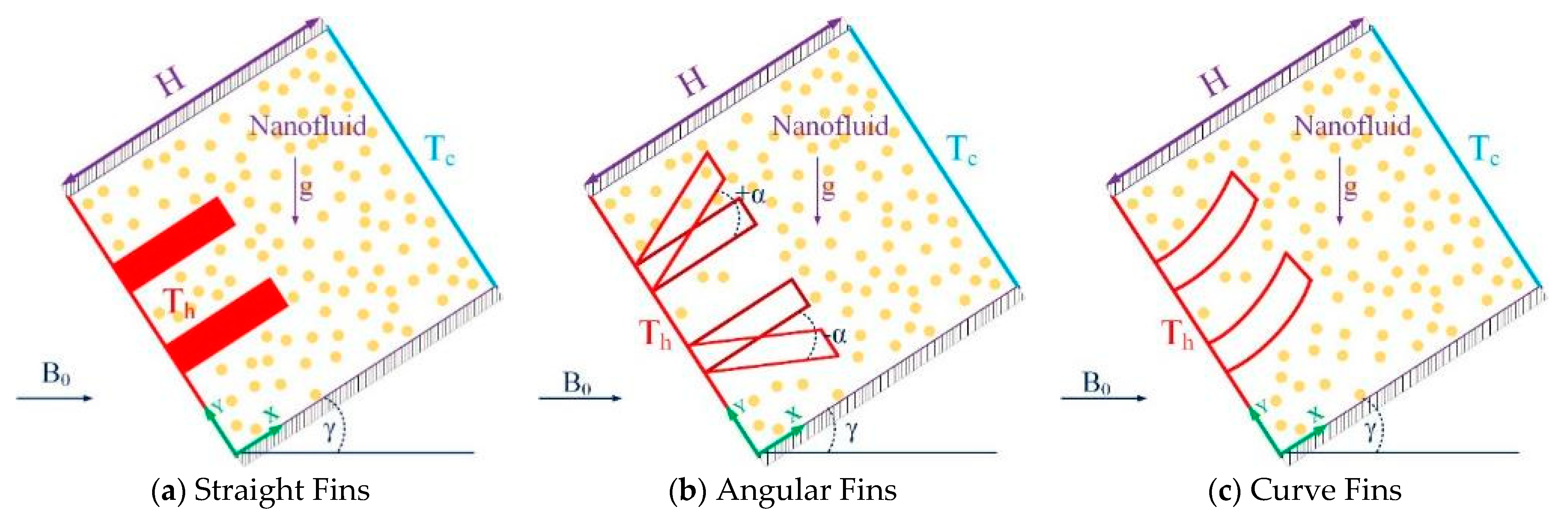
2. Problem Description
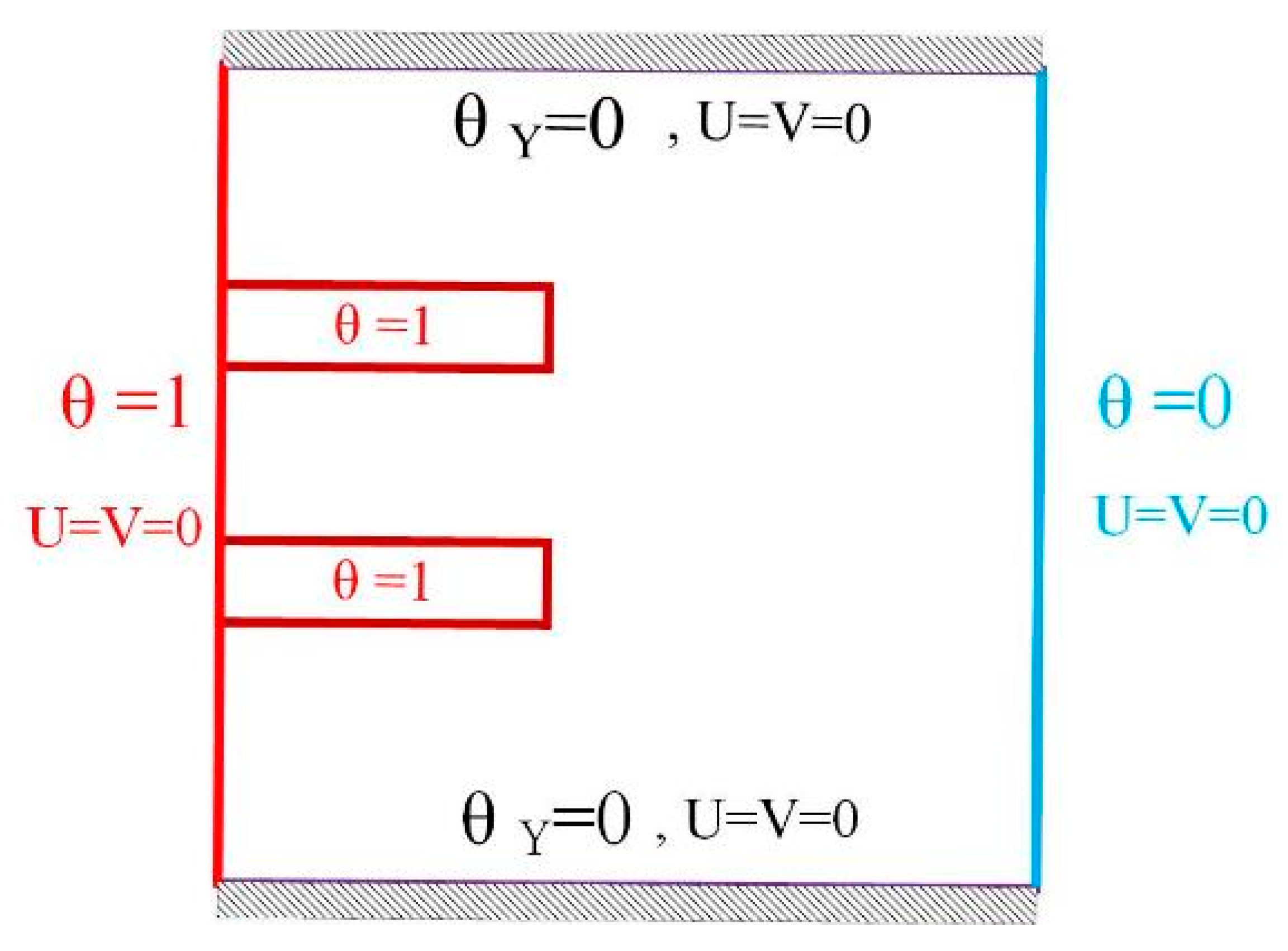
2.1. Governing Equations and Boundary Condition
2.2. Auxiliary Equations
2.3. Numerical Procedure
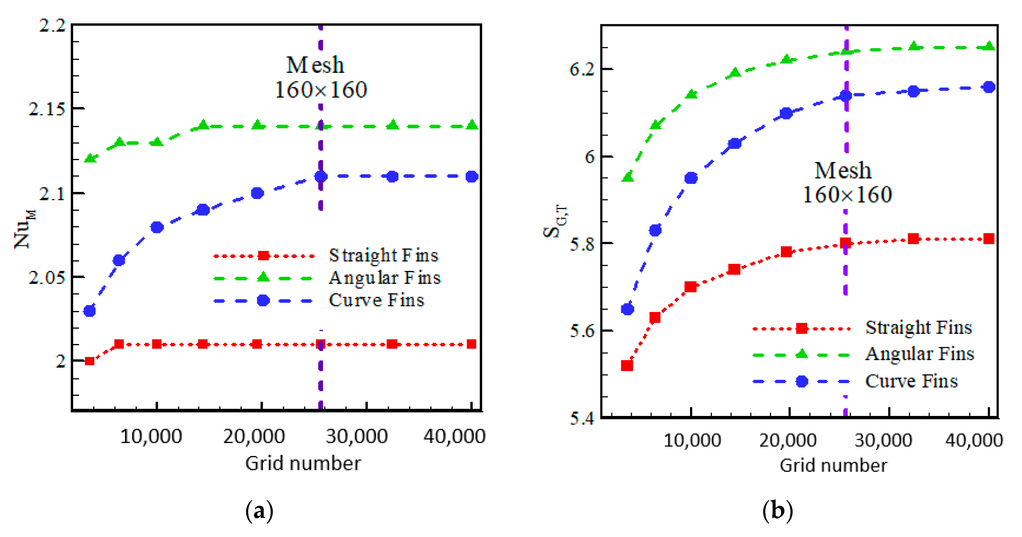
2.4. Grid Analysis
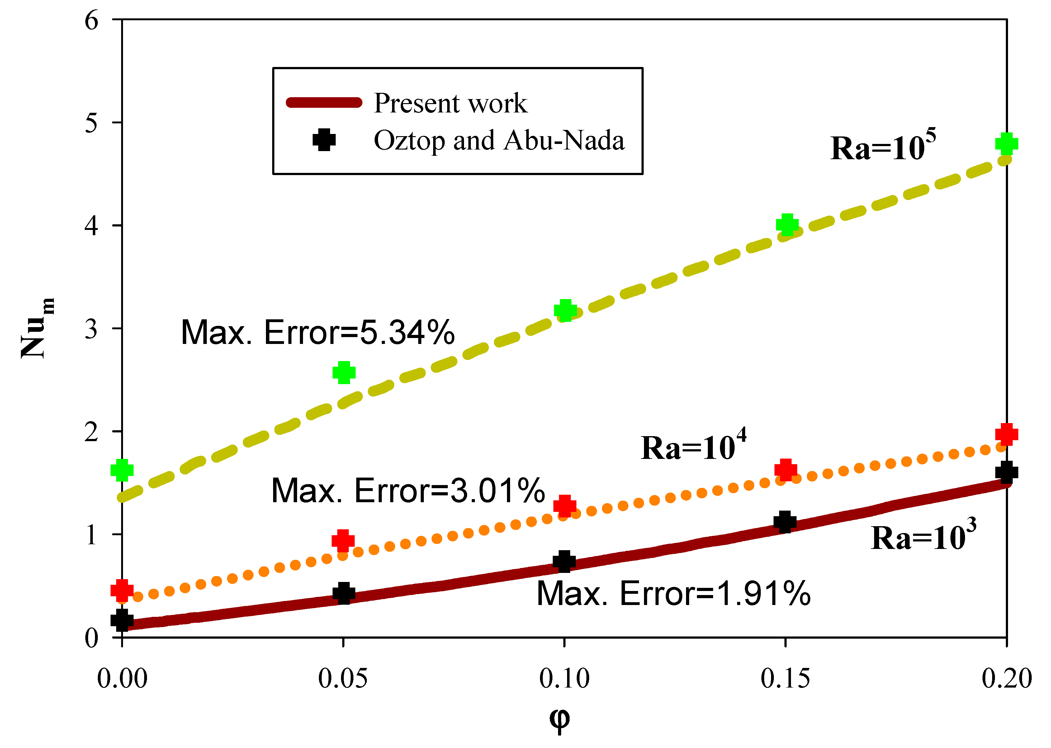
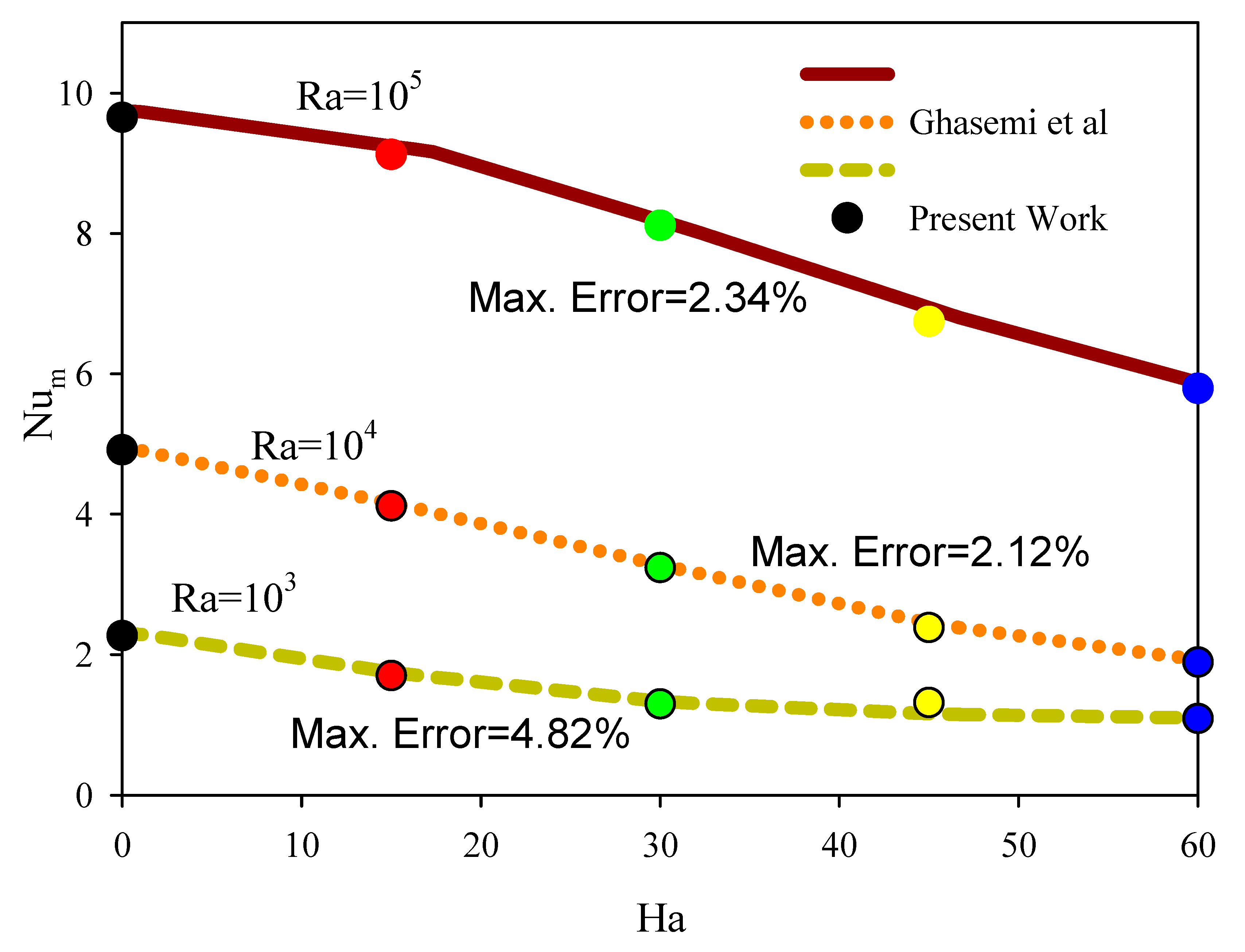
2.5. Validation
3. Results and Discussion
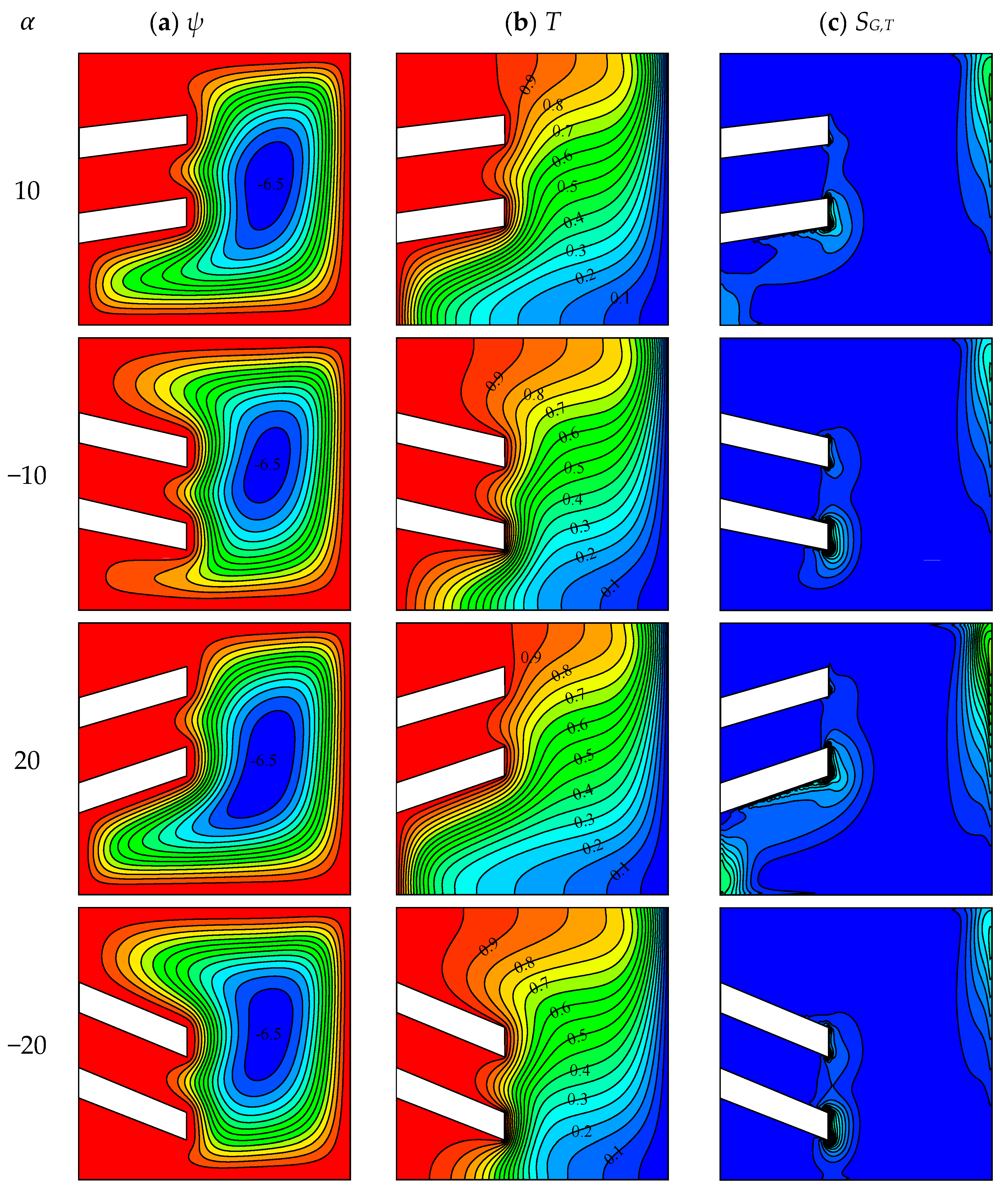
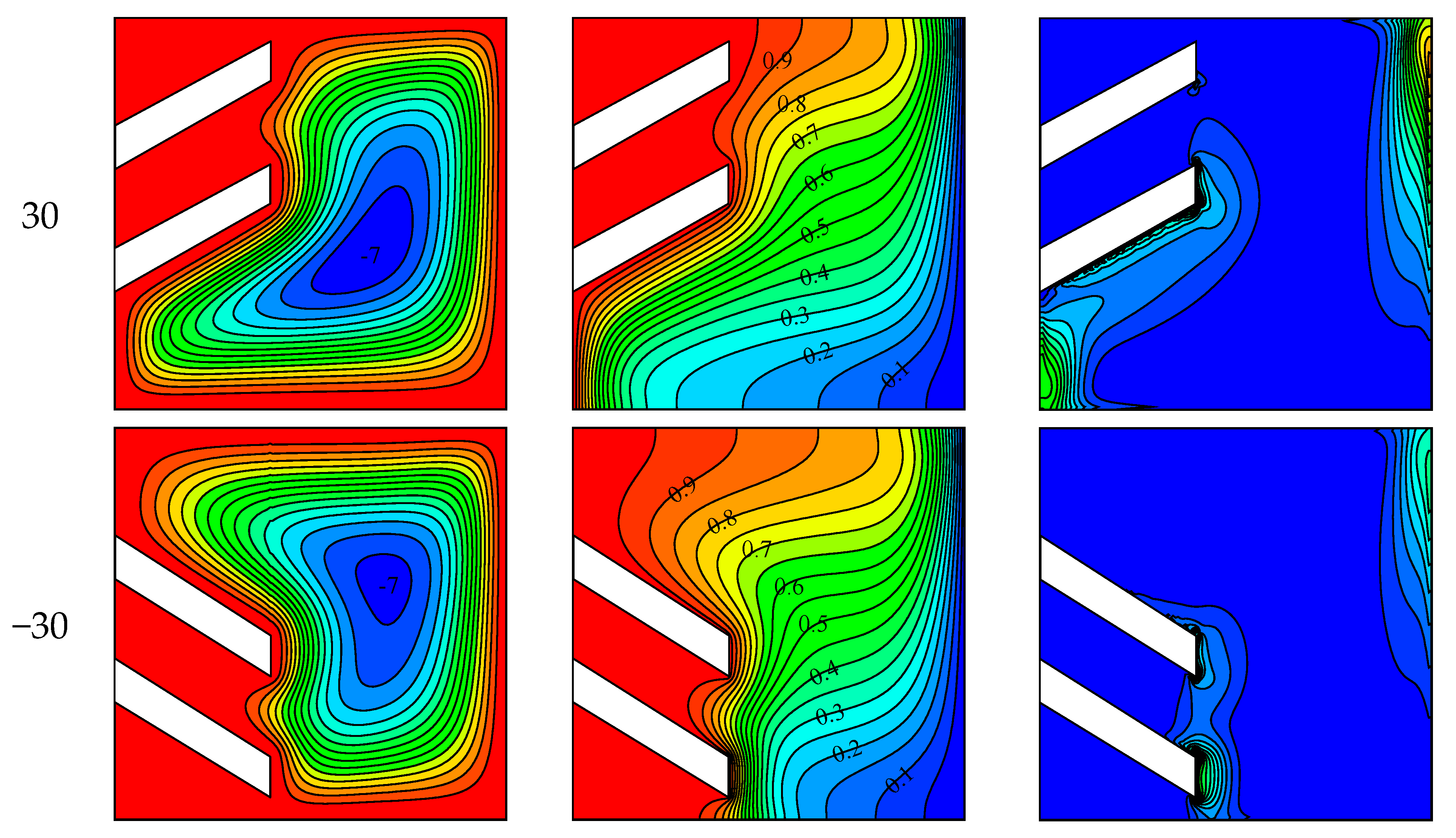
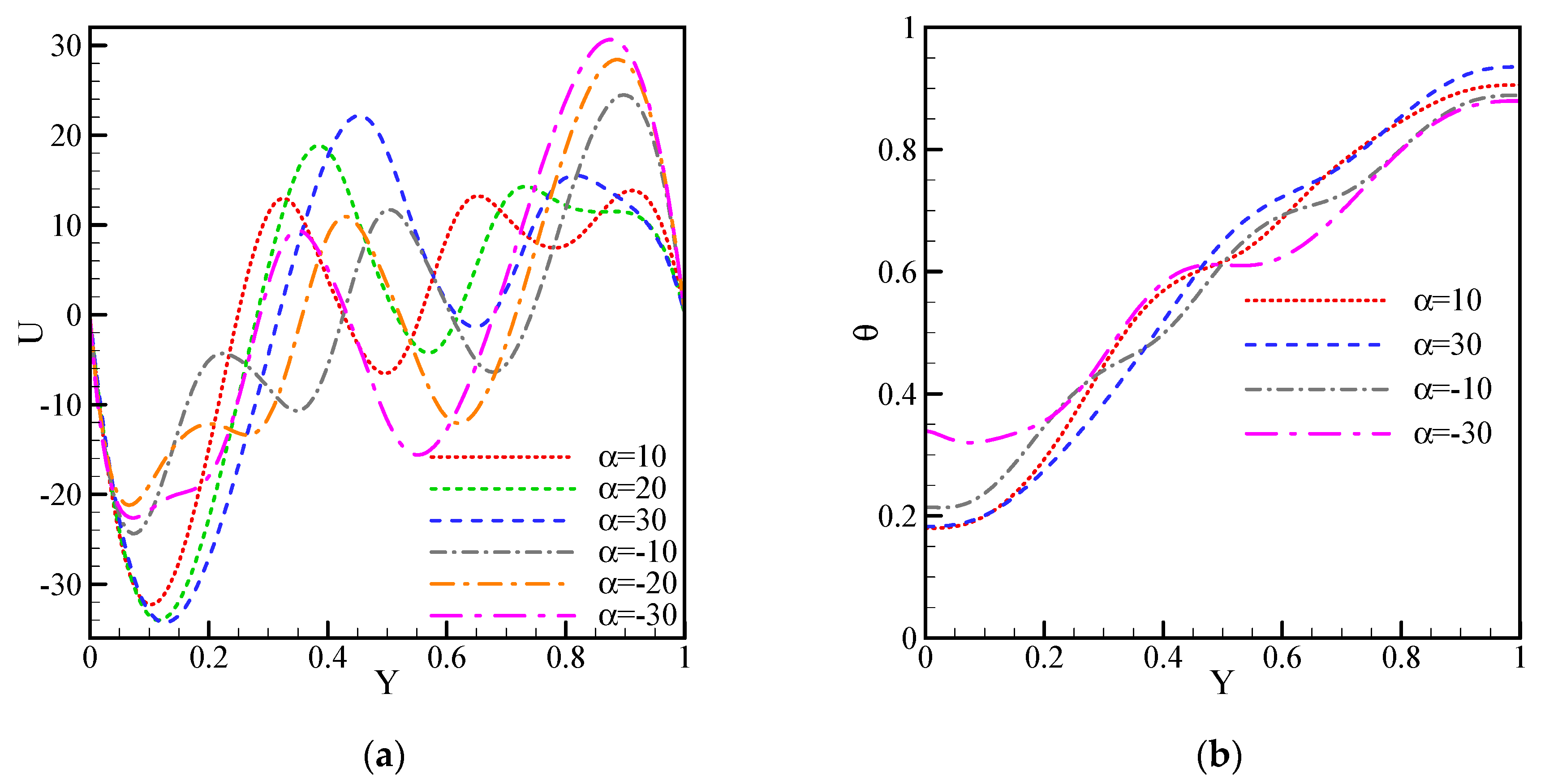
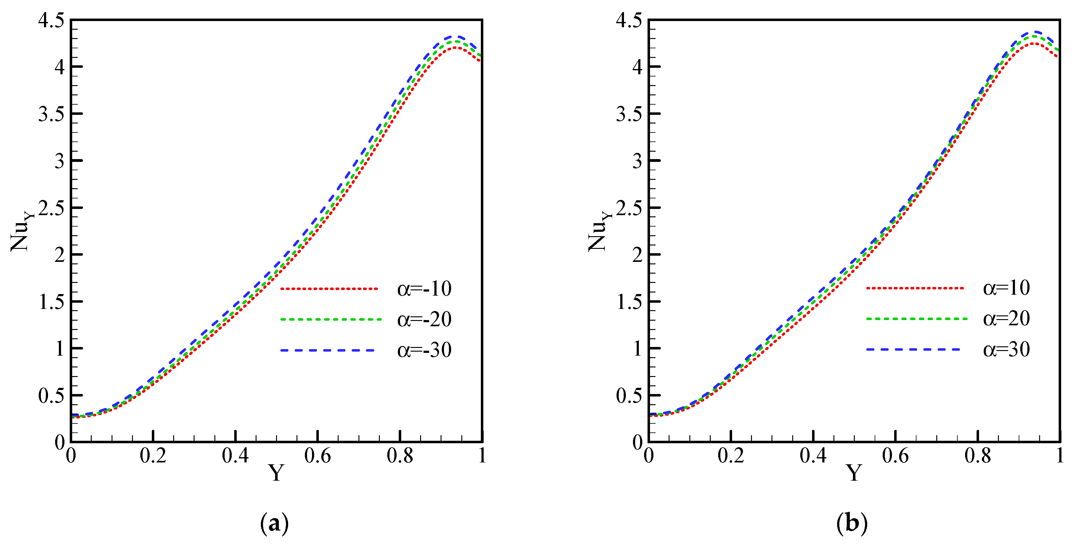
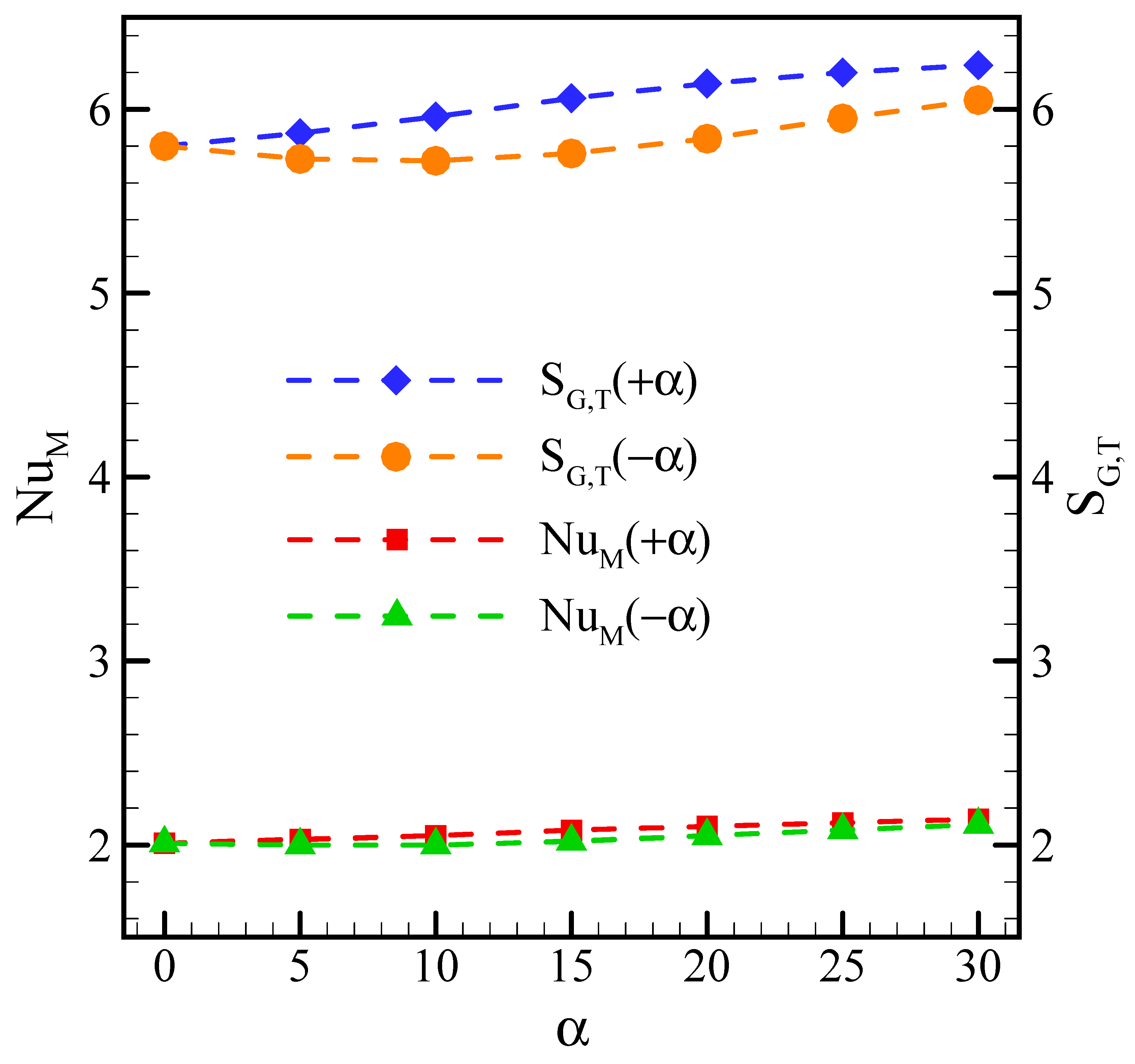
3.1. Effect of Fin Inclination
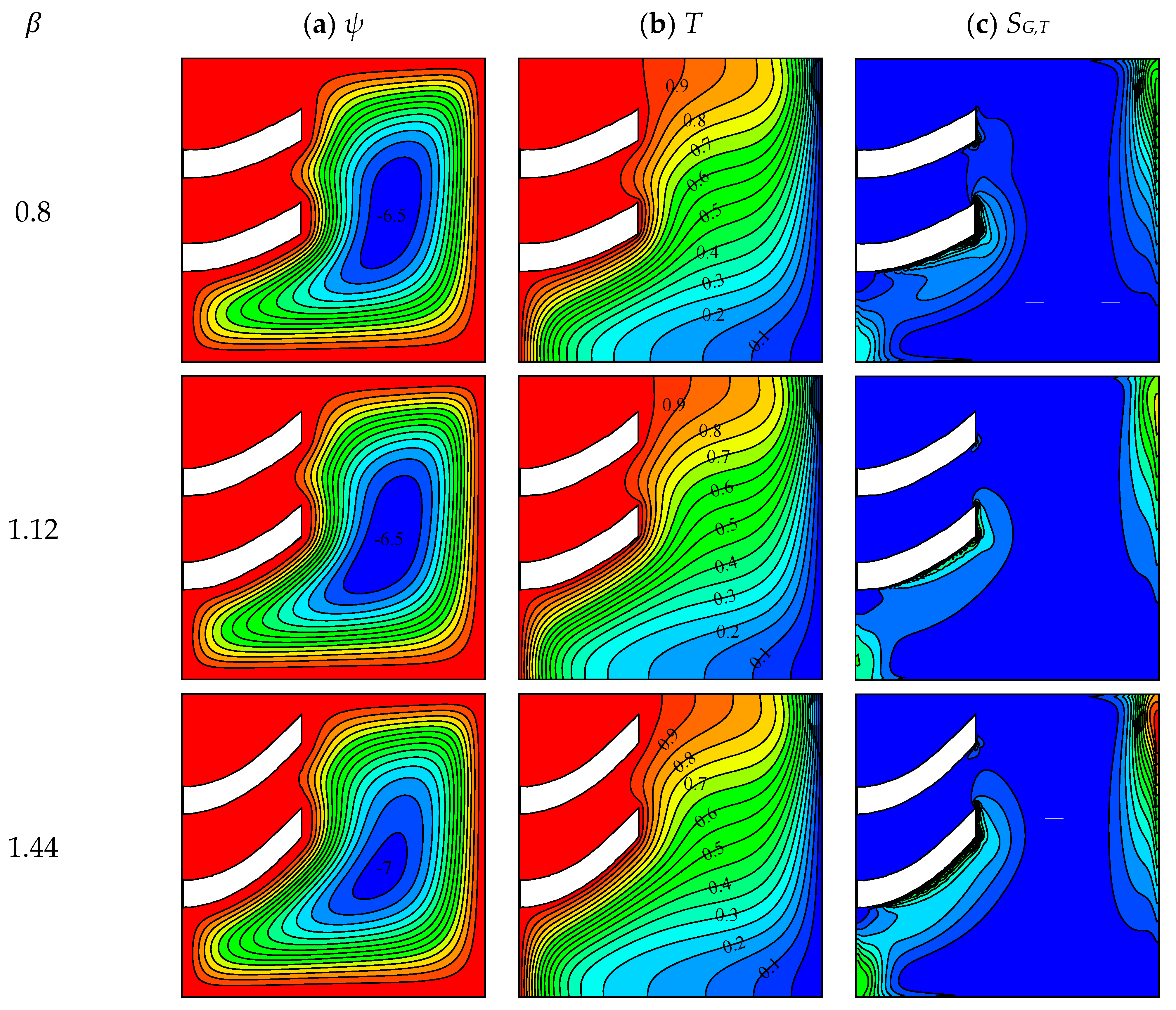
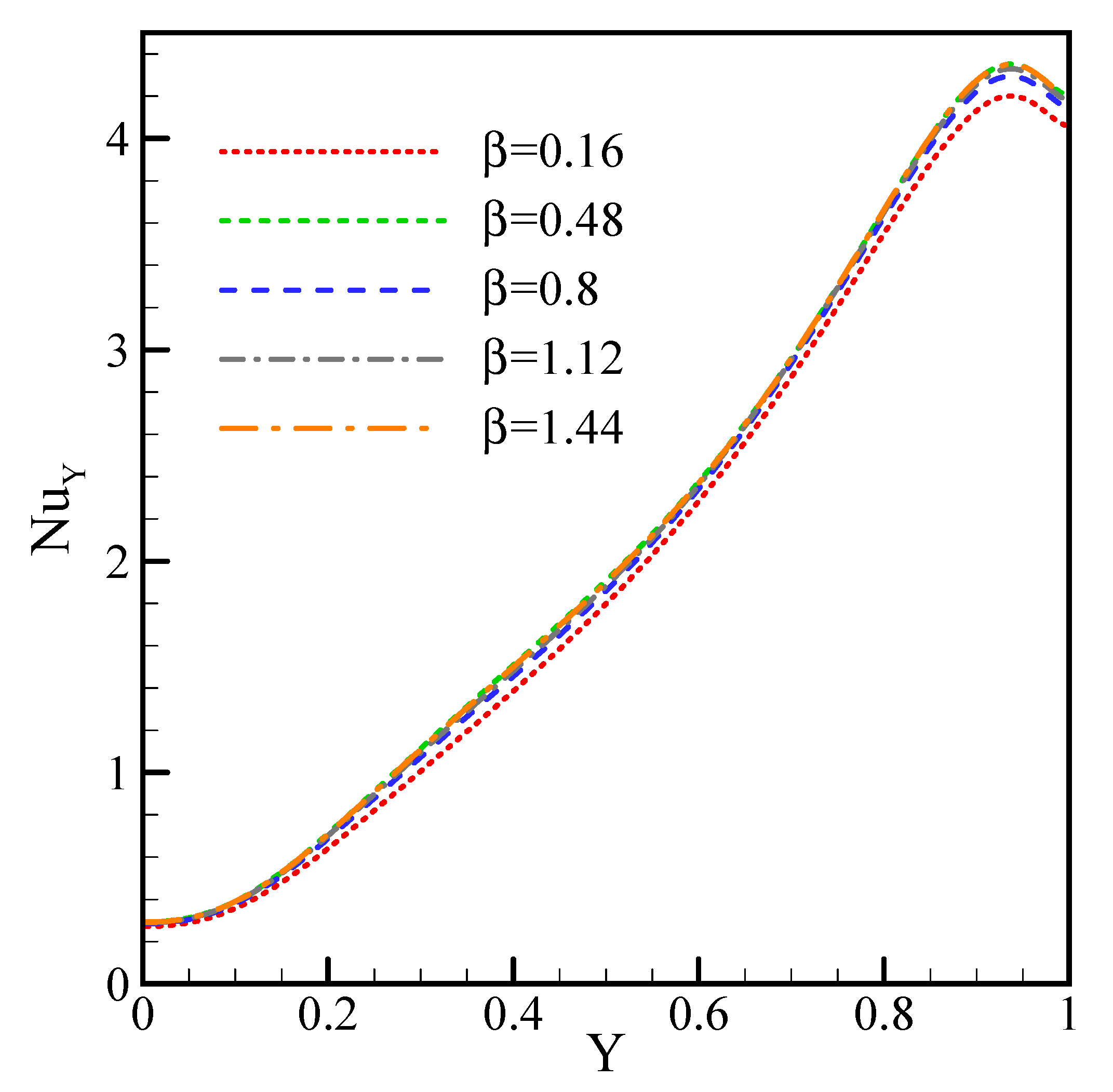
3.2. Effect of Fin Curvature
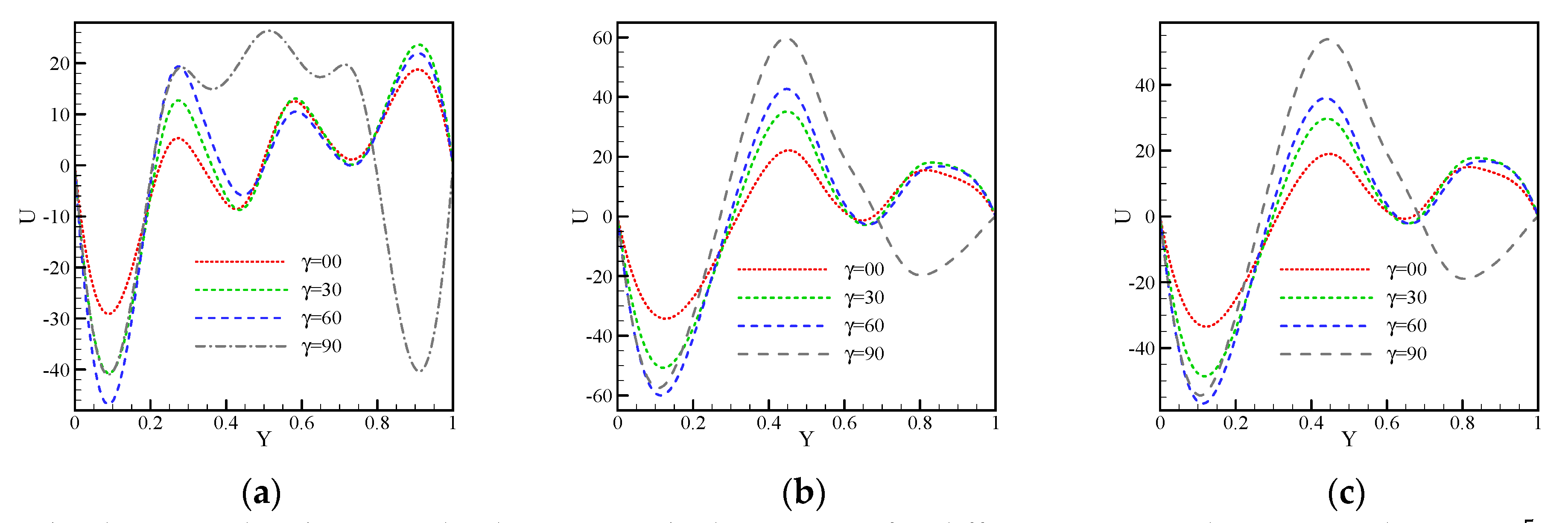
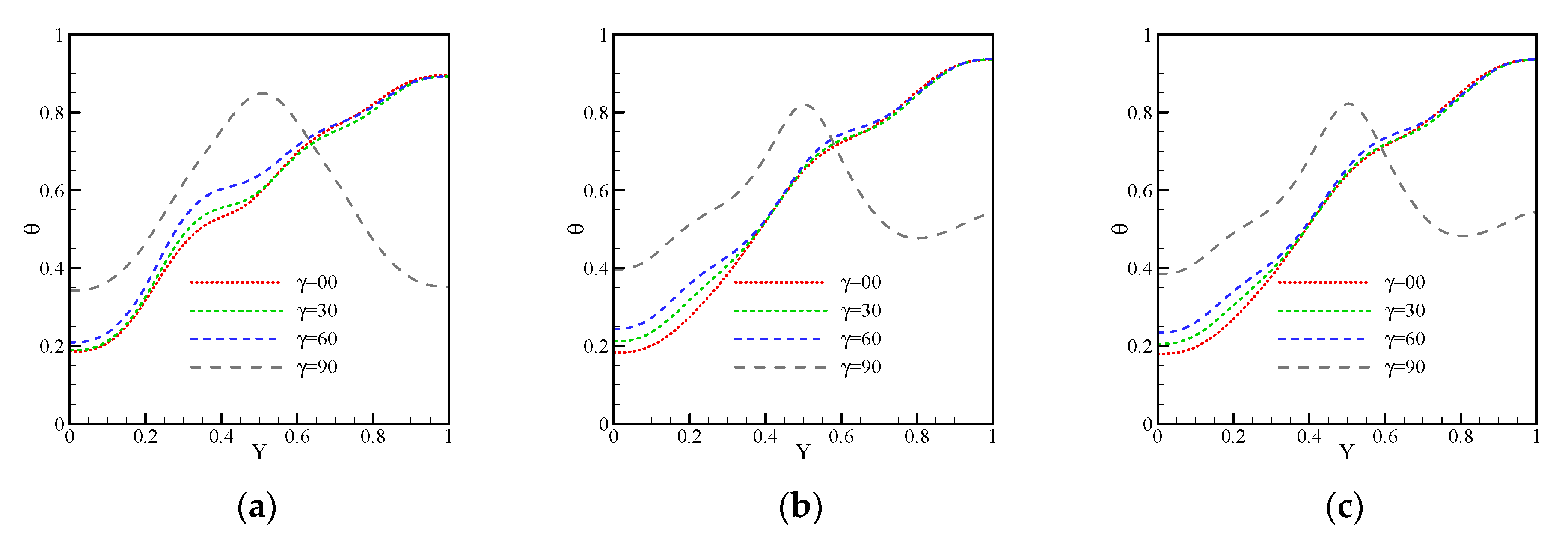
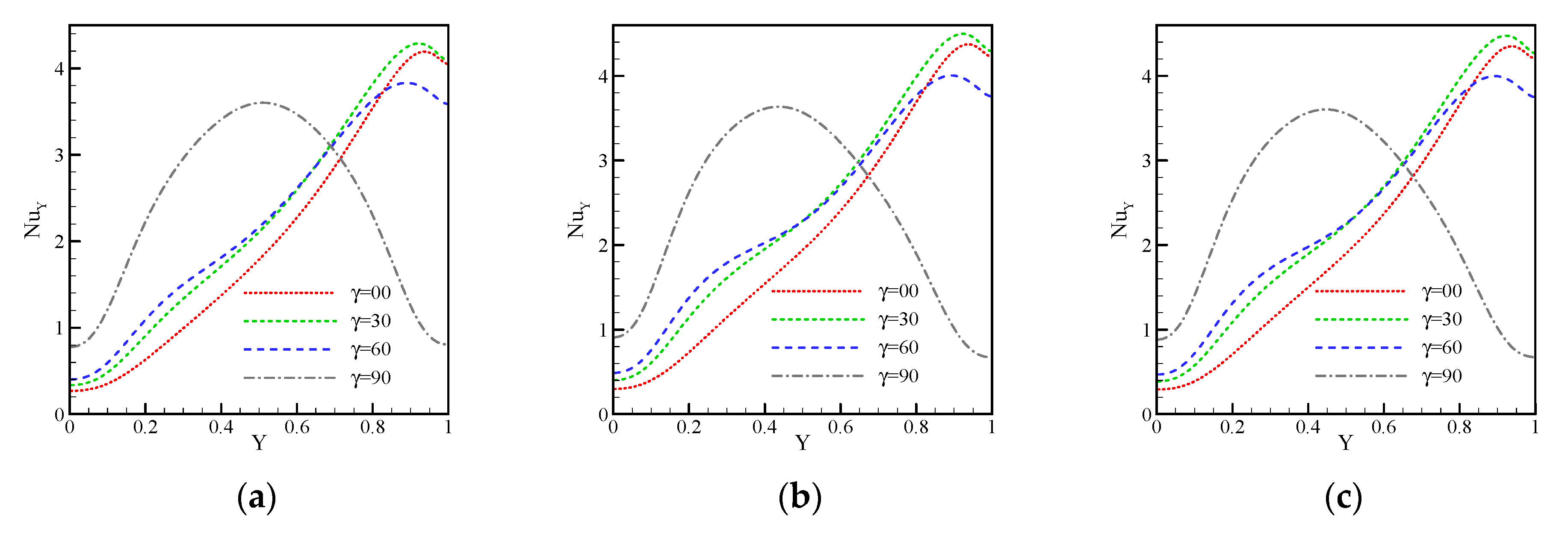
3.3. Effect of Cavity Inclination
3.4. Effect of Ha
4. Conclusions
- The maximum values of Nu and GOE are, respectively, 2.11 and 6.15 W/s, which occurs in the dimensionless curvature of the fin equal to 0.48.
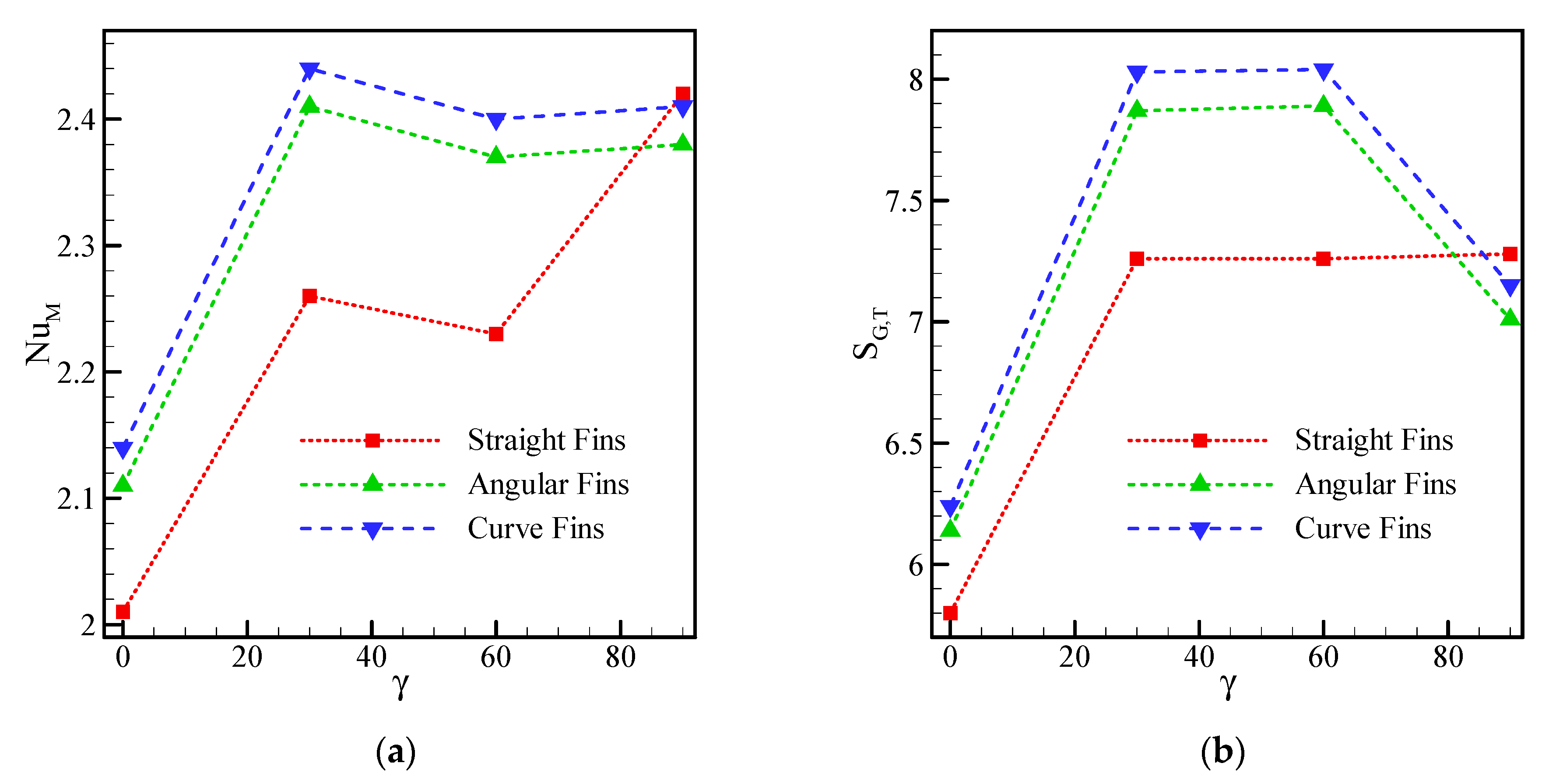
- The highest and lowest HTRs belong to curved fins at a cavity angle of 45 and straight fins at an angle of zero, respectively.
- As the fin angle increases, the HTR and GOE increase.
- By examining the cavity angle, the highest entropy production was observed for angled fins at a cavity angle of 45. The lowest rate occurs in straight fins at a cavity angle of zero.
- In the horizontal cavity, by changing the fin angle, the heat transfer can be increased by a maximum of 6.4%, while it can be increased by a maximum of 4.9% by bending the fins.
- With increasing the Hartmann number from 0 to 40, Nu and GOE decreased by 37.9% and 33.8%, respectively.
Author Contributions
Funding
Institutional Review Board Statement
Informed Consent Statement
Data Availability Statement
Acknowledgments
Conflicts of Interest
Nomenclature
| B0 | Magnetic field strength | ||
| Cp | Specific heat | ||
| g | Gravitational acceleration [m/s2] | Greek symbols | |
| h | Heat transfer coefficient | Fin angle | |
| H | Enclosure non-dimensional length [-] | β | Curve fin parameter |
| Ha | Hartmann number | γ | Cavity angle |
| k | Thermal conductivity | Irreversibility distribution ratio | |
| l | Enclosure length [m] | Temperature | |
| Nusselt number [-] | Dynamic viscosity | ||
| Pressure | Density | ||
| P | Non-dimensional pressure | Electrical conductivity | |
| Pr | Prandtl number | Solid volume fraction | |
| Ra | Rayleigh number | Subscripts | |
| Entropy generation [W/K] | f | Base fluid | |
| T | Temperature [K] | nf | Nanofluid |
| u, v | Velocity components in x and y directions | M | Average |
| U, V | Velocity component | p | Particle |
| x,y | Cartesian coordinates, | G,T | Total generation |
| X,Y | Coordinates , [-] | ||
References
- Parsa, S.M.; Javadi, D.; Rahbar, A.; Majidniya, M.; Salimi, M.; Amidpour, Y.; Amidpour, M. Experimental investigation at a summit above 13,000 ft on active solar still water purification powered by photovoltaic: A comparative study. Desalination 2020, 476, 114146. [Google Scholar] [CrossRef]
- Parsa, S.M.; Javadi, D.; Rahbar, A.; Majidniya, M.; Aberoumand, S.; Amidpour, Y.; Amidpour, M. Experimental assessment on passive solar distillation system on Mount Tochal at the height of 3964 m: Study at high altitude. Desalination 2019, 466, 77–88. [Google Scholar] [CrossRef]
- Aghakhani, S.; Pordanjani, A.H.; Karimipour, A.; Abdollahi, A.; Afrand, M. Numerical investigation of heat transfer in a power-law non-Newtonian fluid in a C-Shaped cavity with magnetic field effect using finite difference lattice Boltzmann method. Comput. Fluids 2018, 176, 51–67. [Google Scholar] [CrossRef]
- Pordanjani, A.H.; Aghakhani, S.; Afrand, M.; Mahmoudi, B.; Mahian, O.; Wongwises, S. An updated review on application of nanofluids in heat exchangers for saving energy. Energy Convers. Manag. 2019, 198, 111886. [Google Scholar] [CrossRef]
- Salat, J.; Xin, S.; Joubert, P.; Sergent, A.; Penot, F.; Le Quéré, P. Experimental and numerical investigation of turbulent natural convection in a large air-filled cavity. Int. J. Heat Fluid Flow 2004, 25, 824–832. [Google Scholar] [CrossRef]
- Parsa, S.M.; Rahbar, A.; Koleini, M.; Javadi, Y.D.; Afrand, M.; Rostami, S.; Amidpour, M. First approach on nanofluid-based solar still in high altitude for water desalination and solar water disinfection (SODIS). Desalination 2020, 491, 114592. [Google Scholar] [CrossRef]
- Parsa, S.M.; Rahbar, A.; Koleini, M.; Aberoumand, S.; Afrand, M.; Amidpour, M. A renewable energy-driven thermoelectric-utilized solar still with external condenser loaded by silver/nanofluid for simultaneously water disinfection and desalination. Desalination 2020, 480, 114354. [Google Scholar] [CrossRef]
- Parsa, S.M.; Yazdani, A.; Dhahad, H.; Alawee, W.H.; Hesabi, S.; Norozpour, F.; Javadi, D.; Ali, H.M.; Afrand, M. Effect of Ag, Au, TiO2 metallic/metal oxide nanoparticles in double-slope solar stills via thermodynamic and environmental analysis. J. Clean. Prod. 2021, 311, 127689. [Google Scholar] [CrossRef]
- Giwa, S.O.; Sharifpur, M.; Ahmadi, M.H.; Murshed, S.M.S.; Meyer, J.P. Experimental Investigation on Stability, Viscosity, and Electrical Conductivity of Water-Based Hybrid Nanofluid of MWCNT-Fe2O3. Nanomaterials 2021, 11, 136. [Google Scholar] [CrossRef]
- Giwa, S.; Sharifpur, M.; Ahmadi, M.H.; Meyer, J.P. A review of magnetic field influence on natural convection heat transfer performance of nanofluids in square cavities. J. Therm. Anal. Calorim. 2020, 1–43. [Google Scholar] [CrossRef]
- Mahdavi, M.; Sharifpur, M.; Ahmadi, M.H.; Meyer, J.P. Nanofluid flow and shear layers between two parallel plates: A simulation approach. Eng. Appl. Comput. Fluid Mech. 2020, 14, 1536–1545. [Google Scholar] [CrossRef]
- Mahdavi, M.; Garbadeen, I.; Sharifpur, M.; Ahmadi, M.H.; Meyer, J.P. Study of particle migration and deposition in mixed convective pipe flow of nanofluids at different inclination angles. J. Therm. Anal. Calorim. 2019, 135, 1563–1575. [Google Scholar] [CrossRef]
- Mahdavi, M.; Sharifpur, M.; Ahmadi, M.H.; Meyer, J.P. Aggregation study of Brownian nanoparticles in convective phenomena. J. Therm. Anal. Calorim. 2019, 135, 111–121. [Google Scholar] [CrossRef]
- Jahanshahi, M.; Hosseinizadeh, S.; Alipanah, M.; Dehghani, A.; Vakilinejad, G. Numerical simulation of free convection based on experimental measured conductivity in a square cavity using Water/SiO2 nanofluid. Int. Commun. Heat Mass Transf. 2010, 37, 687–694. [Google Scholar] [CrossRef]
- Sajid, M.U.; Ali, H.M. Recent advances in application of nanofluids in heat transfer devices: A critical review. Renew. Sustain. Energy Rev. 2019, 103, 556–592. [Google Scholar] [CrossRef]
- Mahmoudi, A.H.; Shahi, M.; Raouf, A.H.; Ghasemian, A. Numerical study of natural convection cooling of horizontal heat source mounted in a square cavity filled with nanofluid. Int. Commun. Heat Mass Transf. 2010, 37, 1135–1141. [Google Scholar] [CrossRef]
- Reza-E-Rabbi, S.; Ahmmed, S.F.; Arifuzzaman, S.; Sarkar, T.; Khan, S. Computational modelling of multiphase fluid flow behaviour over a stretching sheet in the presence of nanoparticles. Eng. Sci. Technol. Int. J. 2020, 23, 605–617. [Google Scholar] [CrossRef]
- Raisi, A. The effect of conductive baffles on natural convection in a power-law fluid-filled square cavity. J. Braz. Soc. Mech. Sci. Eng. 2018, 40, 33. [Google Scholar] [CrossRef]
- Armaghani, T.; Kasaeipoor, A.; Izadi, M.; Pop, I. MHD natural convection and entropy analysis of a nanofluid inside T-shaped baffled enclosure. Int. J. Numer. Methods Heat Fluid Flow 2018, 28, 2916–2941. [Google Scholar] [CrossRef]
- Khorasanizadeh, H.; Amani, J.; Nikfar, M. Numerical investigation of Cu-water nanofluid natural convection and GOE within a cavity with an embedded conductive baffle. Sci. Iran. 2012, 19, 1996–2003. [Google Scholar] [CrossRef] [Green Version]
- Kandaswamy, P.; Lee, J.; Hakeem, A.A.; Saravanan, S. Effect of baffle–cavity ratios on buoyancy convection in a cavity with mutually orthogonal heated baffles. Int. J. Heat Mass Transf. 2008, 51, 1830–1837. [Google Scholar] [CrossRef]
- Asl, A.K.; Hossainpour, S.; Rashidi, M.M.; Sheremet, M.; Yang, Z. Comprehensive investigation of solid and porous fins influence on natural convection in an inclined rectangular enclosure. Int. J. Heat Mass Transf. 2019, 133, 729–744. [Google Scholar] [CrossRef]
- Khanafer, K.; AlAmiri, A.; Bull, J. Laminar natural convection heat transfer in a differentially heated cavity with a thin porous fin attached to the hot wall. Int. J. Heat Mass Transf. 2015, 87, 59–70. [Google Scholar] [CrossRef]
- Liu, Y.; Lei, C.; Patterson, J.C. Natural convection in a differentially heated cavity with two horizontal adiabatic fins on the sidewalls. Int. J. Heat Mass Transf. 2014, 72, 23–36. [Google Scholar] [CrossRef]
- Alnaqi, A.A.; Aghakhani, S.; Pordanjani, A.H.; Bakhtiari, R.; Asadi, A.; Tran, M.-D. Effects of magnetic field on the convective HTR and GOE of a nanofluid in an inclined square cavity equipped with a conductor fin: Considering the radiation effect. Int. J. Heat Mass Transf. 2019, 133, 256–267. [Google Scholar] [CrossRef]
- Al-Rashed, A.A. Investigating the effect of alumina nanoparticles on heat transfer and GOE inside a square enclosure equipped with two inclined blades under magnetic field. Int. J. Mech. Sci. 2019, 152, 312–328. [Google Scholar] [CrossRef]
- Aghakhani, S.; Ghasemi, B.; Pordanjani, A.H.; Wongwises, S.; Afrand, M. Effect of replacing nanofluid instead of water on heat transfer in a channel with extended surfaces under a magnetic field. Int. J. Numer. Methods Heat Fluid Flow 2019, 29, 1249–1271. [Google Scholar] [CrossRef]
- Yan, S.-R.; Aghakhani, S.; Karimipour, A. Influence of a membrane on nanofluid heat transfer and irreversibilities inside a cavity with two constant-temperature semicircular sources on the lower wall: Applicable to solar collectors. Phys. Scr. 2020, 95, 085702. [Google Scholar] [CrossRef]
- Tian, M.-W.; Rostami, S.; Aghakhani, S.; Goldanlou, A.S.; Qi, C. A techno-economic investigation of 2D and 3D configurations of fins and their effects on heat sink efficiency of MHD hybrid nanofluid with slip and non-slip flow. Int. J. Mech. Sci. 2021, 189, 105975. [Google Scholar] [CrossRef]
- Selimefendigil, F.; Öztop, H.F. Corrugated conductive partition effects on MHD free convection of CNT-water nanofluid in a cavity. Int. J. Heat Mass Transf. 2019, 129, 265–277. [Google Scholar] [CrossRef]
- Sajjadi, H.; Delouei, A.A.; Sheikholeslami, M.; Atashafrooz, M.; Succi, S. Simulation of three dimensional MHD natural convection using double MRT Lattice Boltzmann method. Phys. A Stat. Mech. Its Appl. 2019, 515, 474–496. [Google Scholar] [CrossRef]
- Ellahi, R.; Zeeshan, A.; Shehzad, N.; Alamri, S.Z. Structural impact of kerosene-Al2O3 nanoliquid on MHD Poiseuille flow with variable thermal conductivity: Application of cooling process. J. Mol. Liq. 2018, 264, 607–615. [Google Scholar] [CrossRef]
- Rashad, A.; Armaghani, T.; Chamkha, A.; Mansour, M. GOE and MHD natural convection of a nanofluid in an inclined square porous cavity: Effects of a heat sink and source size and location. Chin. J. Phys. 2018, 56, 193–211. [Google Scholar] [CrossRef]
- Sheikholeslami, M.; Sadoughi, M. Mesoscopic method for MHD nanofluid flow inside a porous cavity considering various shapes of nanoparticles. Int. J. Heat Mass Transf. 2017, 113, 106–114. [Google Scholar] [CrossRef]
- Arifuzzaman, S.; Khan, S.; Al-Mamun, A.; Reza-E-Rabbi, S.; Biswas, P.; Karim, I. Hydrodynamic stability and heat and mass transfer flow analysis of MHD radiative fourth-grade fluid through porous plate with chemical reaction. J. King Saud Univ. Sci. 2019, 31, 1388–1398. [Google Scholar] [CrossRef]
- Aghakhani, S.; Pordanjani, A.H.; Afrand, M.; Sharifpur, M.; Meyer, J.P. Natural convective heat transfer and entropy generation of alumina/water nanofluid in a tilted enclosure with an elliptic constant temperature: Applying magnetic field and radiation effects. Int. J. Mech. Sci. 2020, 174, 105470. [Google Scholar] [CrossRef]
- Mahian, O.; Mahmud, S.; Pop, I. Analysis of first and second laws of thermodynamics between two isothermal cylinders with relative rotation in the presence of MHD flow. Int. J. Heat Mass Transf. 2012, 55, 4808–4816. [Google Scholar] [CrossRef]
- Pordanjani, A.H.; Jahanbakhshi, A.; Nadooshan, A.A.; Afrand, M. Effect of two isothermal obstacles on the natural convection of nanofluid in the presence of magnetic field inside an enclosure with sinusoidal wall temperature distribution. Int. J. Heat Mass Transf. 2018, 121, 565–578. [Google Scholar] [CrossRef]
- Pordanjani, A.H.; Aghakhani, S. Numerical Investigation of Natural Convection and Irreversibilities between Two Inclined Concentric Cylinders in Presence of Uniform Magnetic Field and Radiation. Heat Transf. Eng. 2021, 1–21. [Google Scholar] [CrossRef]
- Salari, M.; Kasaeipoor, A.; Malekshah, E.H. Three-dimensional natural convection and entropy generation in tall rectangular enclosures filled with stratified nanofluid/air fluids. Heat Transf. Res. 2018, 49, 685–702. [Google Scholar] [CrossRef]
- Al-Zamily, A.M.J. Analysis of natural convection and GOE in a cavity filled with multi-layers of porous medium and nanofluid with a heat generation. Int. J. Heat Mass Transf. 2017, 106, 1218–1231. [Google Scholar] [CrossRef]
- Chamkha, A.; Ismael, M.; Kasaeipoor, A.; Armaghani, T. GOE and Natural Convection of CuO-Water Nanofluid in C-Shaped Cavity under Magnetic Field. Entropy 2016, 18, 50. [Google Scholar] [CrossRef] [Green Version]
- Ali, M.M.; Akhter, R.; Alim, A. MHD natural convection and entropy generation in a grooved enclosure filled with nanofluid using two-component non-homogeneous model. SN Appl. Sci. 2020, 2, 1–25. [Google Scholar] [CrossRef] [Green Version]
- Li, Z.; Hussein, A.K.; Younis, O.; Afrand, M.; Feng, S. Natural convection and entropy generation of a nanofluid around a circular baffle inside an inclined square cavity under thermal radiation and magnetic field effects. Int. Commun. Heat Mass Transf. 2020, 116, 104650. [Google Scholar] [CrossRef]
- Acharya, S.; Dash, S.K. Natural Convection and Entropy Generation in a Porous Enclosure Filled with Non-Newtonian Nanofluid. J. Thermophys. Heat Transf. 2021, 35, 438–458. [Google Scholar] [CrossRef]
- Zhou, X.; Jiang, Y.; Li, X.; Cheng, K.; Huai, X.; Zhang, X.; Huang, H. Numerical investigation of heat transfer enhancement and GOE of natural convection in a cavity containing nano liquid-metal fluid. Int. Commun. Heat Mass Transf. 2019, 106, 46–54. [Google Scholar] [CrossRef]
- Dutta, S.; Goswami, N.; Biswas, A.K.; Pati, S. Numerical investigation of magnetohydrodynamic natural convection heat transfer and GOE in a rhombic enclosure filled with Cu-water nanofluid. Int. J. Heat Mass Transf. 2019, 136, 777–798. [Google Scholar] [CrossRef]
- Vajjha, R.S.; Das, D.K. Experimental determination of thermal conductivity of three nanofluids and development of new correlations. Int. J. Heat Mass Transf. 2009, 52, 4675–4682. [Google Scholar] [CrossRef]
- Hassani, S.; Saidur, R.; Mekhilef, S.; Hepbasli, A. A new correlation for predicting the thermal conductivity of nanofluids; using dimensional analysis. Int. J. Heat Mass Transf. 2015, 90, 121–130. [Google Scholar] [CrossRef]
- Maxwell, J.C.; Thompson, J.J. A Treatise on Electricity and Magnetism; Clarendon Press: Oxford, UK, 1904. [Google Scholar]
- Brinkman, H.C. The Viscosity of Concentrated Suspensions and Solutions. J. Chem. Phys. 1952, 20, 571–581. [Google Scholar] [CrossRef]
- Oztop, H.F.; Abu-Nada, E. Numerical study of natural convection in partially heated rectangular enclosures filled with nanofluids. Int. J. Heat Fluid Flow 2008, 29, 1326–1336. [Google Scholar] [CrossRef]
- Aminossadati, S.; Ghasemi, B. Natural convection cooling of a localised heat source at the bottom of a nanofluid-filled enclosure. Eur. J. Mech. B Fluids 2009, 28, 630–640. [Google Scholar] [CrossRef]


| Water | 4179 | 0.613 | 997.1 | 0.001 | 0.05 | - |
| 765 | 40 | 3970 | - | 10−12 | 47 |
| β | 0.16 | 0.48 | 0.8 | 1.12 | 1.44 |
|---|---|---|---|---|---|
| NuM | 2.02 | 2.11 | 2.08 | 2.10 | 2.11 |
| SG,T | 5.84 | 6.15 | 6.04 | 6.11 | 6.14 |
| Max NuM | Min NuM | Max SG,T | Min SG,T | |
|---|---|---|---|---|
| Straight Fins | 2.42 ( | 2.01 ( | 7.28 ( | 5.80 ( |
| Angular Fins | 2.43 ( | 2.14 ( | 8.12 ( | 6.24 ( |
| Curve Fins | 2.46 ( | 2.11 ( | 8.04 ( | 6.14 ( |
| Ha | 0 | 10 | 20 | 30 | 40 |
|---|---|---|---|---|---|
| NuM | 2.37 | 2.26 | 2.01 | 1.72 | 1.47 |
| % change NuM | 0.0 | 4.6 | 15.1 | 27.4 | 37.9 |
| SG,T | 6.50 | 6.33 | 5.80 | 5.07 | 4.30 |
| % change SG,T | 0.0 | 2.6 | 10.7 | 22.0 | 33.8 |
Publisher’s Note: MDPI stays neutral with regard to jurisdictional claims in published maps and institutional affiliations. |
© 2021 by the authors. Licensee MDPI, Basel, Switzerland. This article is an open access article distributed under the terms and conditions of the Creative Commons Attribution (CC BY) license (https://creativecommons.org/licenses/by/4.0/).
Share and Cite
Khetib, Y.; Alahmadi, A.A.; Alzaed, A.; Azimy, H.; Sharifpur, M.; Cheraghian, G. Effect of Straight, Inclined and Curved Fins on Natural Convection and Entropy Generation of a Nanofluid in a Square Cavity Influenced by a Magnetic Field. Processes 2021, 9, 1339. https://0-doi-org.brum.beds.ac.uk/10.3390/pr9081339
Khetib Y, Alahmadi AA, Alzaed A, Azimy H, Sharifpur M, Cheraghian G. Effect of Straight, Inclined and Curved Fins on Natural Convection and Entropy Generation of a Nanofluid in a Square Cavity Influenced by a Magnetic Field. Processes. 2021; 9(8):1339. https://0-doi-org.brum.beds.ac.uk/10.3390/pr9081339
Chicago/Turabian StyleKhetib, Yacine, Ahmad Aziz Alahmadi, Ali Alzaed, Hamidreza Azimy, Mohsen Sharifpur, and Goshtasp Cheraghian. 2021. "Effect of Straight, Inclined and Curved Fins on Natural Convection and Entropy Generation of a Nanofluid in a Square Cavity Influenced by a Magnetic Field" Processes 9, no. 8: 1339. https://0-doi-org.brum.beds.ac.uk/10.3390/pr9081339