Article

Research on Feedback-Linearized Sliding Mode Control of Direct-Drive Volume Control Electro-Hydraulic Servo System

1
School of Mechanical Engineering, Yanshan University, Qinhuangdao 066004, China
2
Mechanical and Electrical Engineering, Xinjiang Institute of Engineering, Urumqi 830023, China
*
Author to whom correspondence should be addressed.
Submission received: 16 August 2021 / Revised: 15 September 2021 / Accepted: 16 September 2021 / Published: 18 September 2021

Abstract

:
In this paper, a control strategy combining the feedback linearization theory and sliding mode variable structure theory is proposed to solve various nonlinear factors, uncertainty of external disturbance and high-precision pressure control problems in the Direct-Drive Volume Control (DDVC) electro-hydraulic servo system. The nonlinear mathematical model of the DDVC electro-hydraulic servo system is established, and the nonlinear factors in the system are accurately linearized by the feedback linearization theory. The uncertainty of external disturbance in the system is compensated by the sliding mode control variable structure theory. The feedback-linearized sliding mode control algorithm proposed in this paper is verified using the DDVC electro-hydraulic servo system experimental platform. The experimental results show that, compared with the classical PID control, the proposed control algorithm can effectively improve the pressure output precision, as well as the dynamic response characteristics, of the DDVC system.

1. Introduction

As one of the three core components of new energy vehicles, lithium batteries not only account for about 40% of the cost of vehicles, but their performance also directly determines the safety and range of vehicles. Roll forming is one of the key processes of lithium battery pole pieces, which is very important for the performance of the battery. The thickness consistency of lithium battery pole pieces is an important index to measure the stability of lithium batteries. In order to ensure the consistency of the thickness of lithium battery pole pieces, the thickness accuracy is usually required to be ±0.5 microns, which puts forward a high requirement for the roller press of lithium battery pole pieces. At present, lithium battery pole piece sheet roll forming usually adopts pole sheet rolling mill equipment, and the traditional pole sheet rolling mill adopts electro-hydraulic servo valve control cylinder technology. The traditional valve control system is widely used in aerospace and industrial automation due to its fast dynamic response and high control accuracy. However, it also has disadvantages, such as large throttle loss, low energy efficiency and a system energy utilization rate lower than 40% [1]. The Direct-Drive Volume Control (DDVC) electro-hydraulic servo system is a highly integrated and compact closed pump-controlled drive unit, which is composed of a servo motor, ration pump and servo-hydraulic cylinder, among other parts. Compared with the traditional valve control system, the DDVC system has the technical advantages of a high power–gain ratio, high integration, environmental friendliness and high efficiency and energy saving [2,3]. The DDVC system has been widely used in hydraulic elevators, injection molding machines and other industries in western and European countries [4]. Moog’s Electro-Hydrostatic Actuator (EHA) has been tested on fighter aircraft [5]. However, with the widening of electro-hydraulic servo technology applications, the demand for industrial equipment with motion output precision has grown [6,7]. Pressure flow nonlinearity, hydraulic cylinder friction nonlinearity and other nonlinear characteristics have an increasingly obvious impact on the control performance of the DDVC electro-hydraulic servo system, and these characteristics have gradually become a bottleneck restricting the improvement of the system’s performance [8,9,10,11].
Due to the rapid development of industrial modernization, requirements for the pressure control performance of the DDVC electro-hydraulic servo system have grown. Moreover, the technical realization and research of hardware and software at home and abroad on electro-hydraulic servo pressure control have continuously made great progress. Helian et al. believed that pump flow deviation at a low speed was an important limiting factor for good control performance in Direct-Drive electro-hydraulic servo pressure control. Therefore, a nonlinear pump flow rate mapping was proposed by practical fitting and used in the controller design with the proper nonlinearity compensation of the desired pump flow. Comparative experiment results showed that the proposed control strategy achieved high motion control performance despite the nonlinearities and uncertainties [12]. Kim et al. proposed an improved speed controller based on a robust inner-loop compensator (RIC) to quickly compensate for force control errors caused by externally disturbed rod motion. The reverse driving performance of the force-controlled EHA was improved, and the dynamic force control error was effectively reduced to realize the motor speed control [13]. J H et al. used bypass valves and sliding mode control techniques to bypass oil into the low-pressure chamber to compensate for force control errors, thereby rapidly decompressing the high-pressure chamber. Compared with the traditional force control EHA without bypass flow control, the force control error can be significantly reduced. When the sinusoidal excitation frequency is increased from 1 Hz to 3 Hz, the performance improvement is more obvious [14]. Komstar et al. discussed problems of the position control of electro-hydraulic drives in the presence of unknown disturbances and uncertain plant parameters. In order to overcome the system nonlinearities and ensure robustness against matched disturbances and plant uncertainties, an input–output linearization controller with an integral sliding mode disturbance compensator and second-order sliding mode acceleration observer was developed and experimentally tested. The industrial applicability of the new algorithms was also the scope of the investigation. The test results confirmed a very good tracking performance and robustness against model uncertainties [15]. Koch et al. investigated a laboratory hydraulic setup consisting of a coupled actuating and load cylinder in order to emulate real-world working conditions of heavy equipment such as excavators and loaders. An observer-based control scheme is proposed to regulate the position of the actuating cylinder. It relies on online identification of unknown parameters, as well as reconstruction and compensation of unknown load forces, such that the performance of the closed position feedback loop is superior compared to classical control strategies. The applied method exploits ideas of variable structure systems in the design of both the observer and the parameter identification scheme [16].
Huang et al., from the National University of Defense Technology, derived the dynamic nonlinear model of the system by considering the perturbation and disturbance of the electro-hydraulic servo-valve-controlled force control system and designed the sliding mode variable structure control to compensate for the external disturbance and uncertainty. This algorithm can effectively improve the accuracy of the force tracking control [17]. Han, from Tongji University, designed a control strategy of model feedforward compensation and dead zone compensation for nonlinear disturbance problems such as creep and oscillation in pressure control, which improved the accuracy of pressure control and the robustness of the system [18]. Kou, from the Xian University of Science and Technology, analyzed the influence law of motor on system force and proposed a current controller based on inner-loop motor speed to realize force tracking control and improve the dynamic characteristics of the DDVC electro-hydraulic servo system [19]. Zhu, from Jiangsu University, introduced the Popov frequency criterion method to determine the absolute stability of the DDVC electro-hydraulic servo system under the influence of nonlinear disturbance factors [20].
In this paper, taking the DDVC electro-hydraulic servo system as the main research object, the nonlinear mathematical model of the pressure control of the DDVC electro-hydraulic servo system is constructed. The feedback linearization theory is used to accurately linearize the nonlinear factors in the system. Then, the robust sliding mode variable structure control algorithm is used to improve the control accuracy of the system. Finally, the effectiveness of the method is verified by experiments. Our results show that the control method can effectively improve the force tracking quality of the system and improve the robustness of the system.

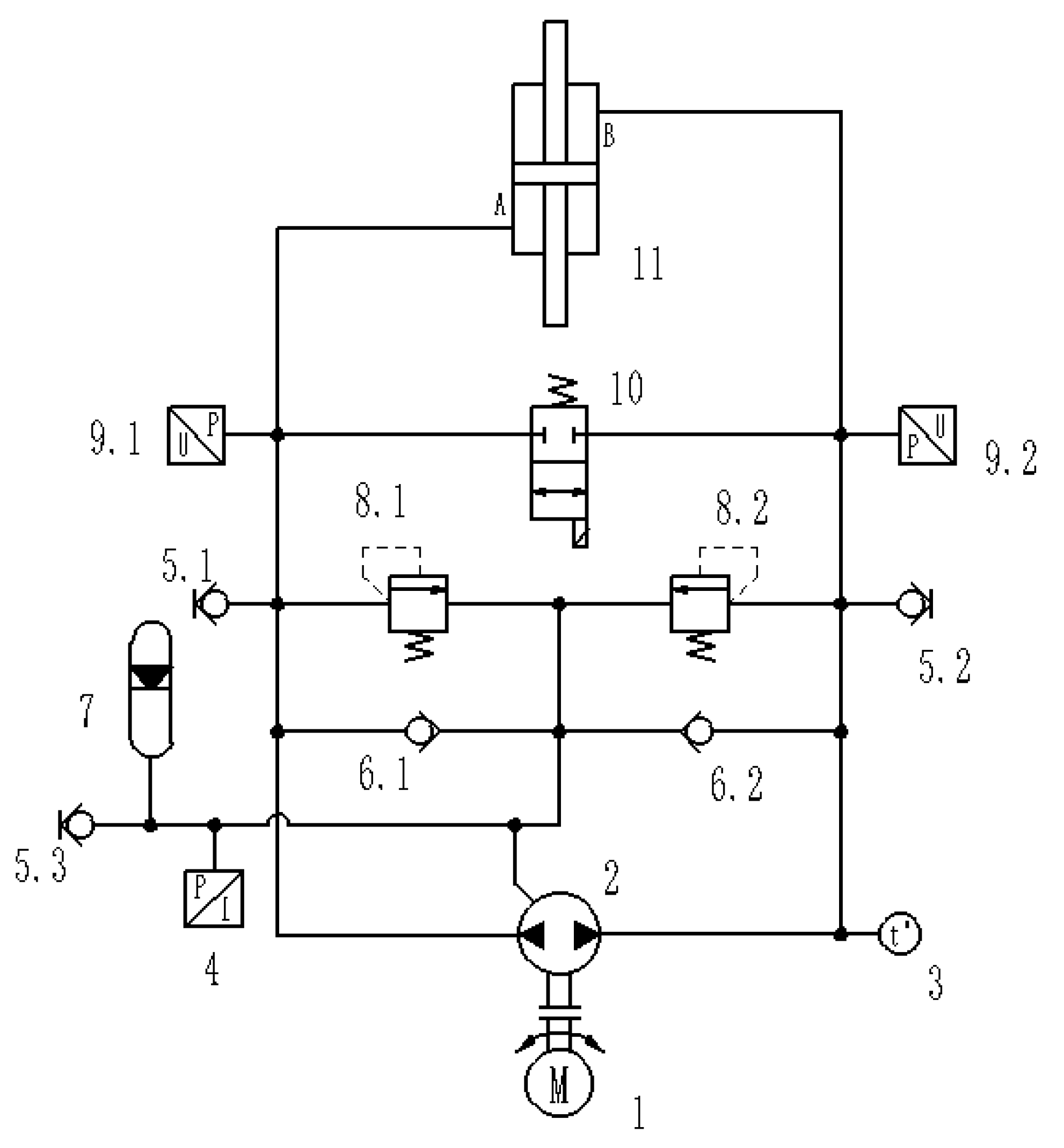
2. Principle of the DDVC Electro-Hydraulic Servo System

The DDVC electro-hydraulic servo system adopts a servo motor–quantitative pump–hydraulic cylinder integration volume control scheme, with a small equipment volume, simple pipeline layout, no throttle overflow loss, high reliability, high safety, high precision and other characteristics. The basic working principle diagram is shown in Figure 1.
The system uses a servo motor to drive the quantitative pump coaxial. The quantitative pump suction and discharge port are directly connected with the hydraulic cylinder two-load oil port. The accumulator with a check valve is used to supplement the system oil, and the relief valve is used as a safety valve to prevent the system pressure from exceeding the safety limit value. The controller controls the speed and torque of the servo motor and adjusts the displacement, speed and force of the hydraulic cylinder by outputting control instruction.
In this paper, high-precision pressure control is realized by controlling the motor input signal to adjust the speed.

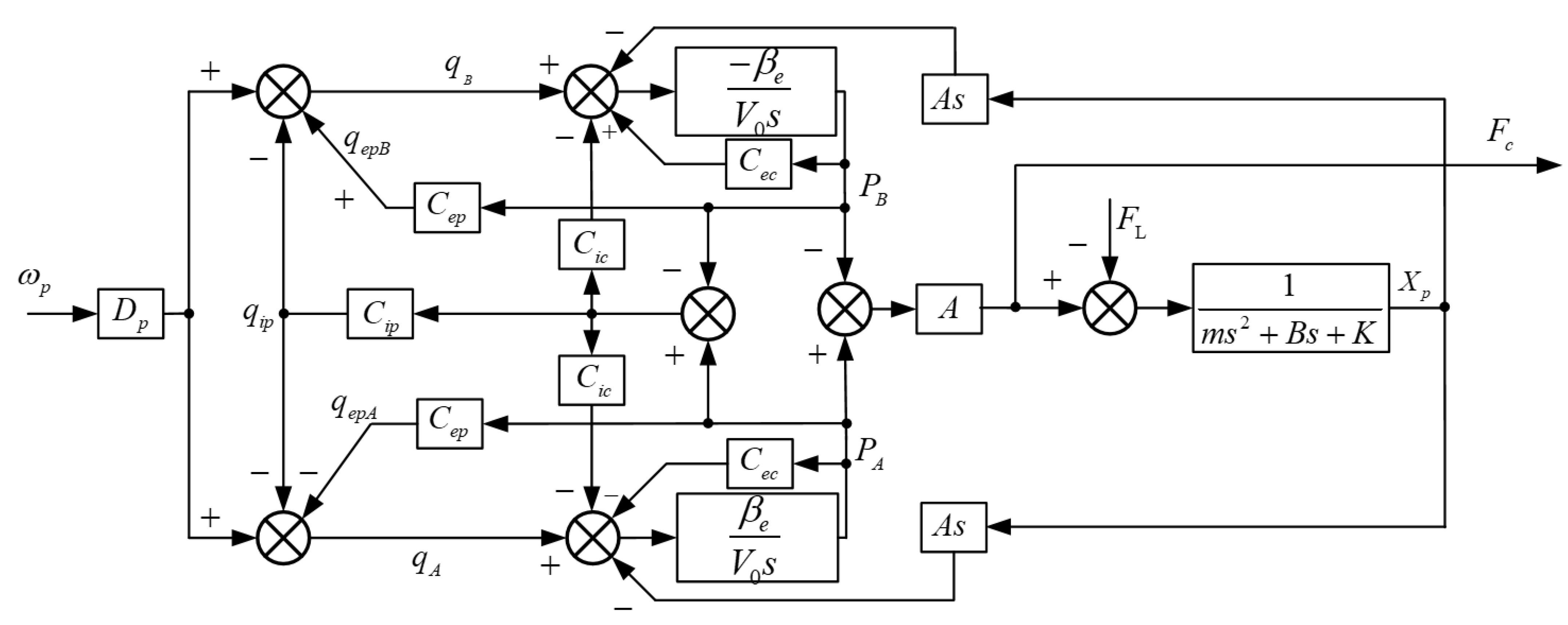
3. Nonlinear Mathematical Model of the DDVC Electro-Hydraulic Servo System

3.1. Servo Motor Control Unit

The AC servo motor is responsible for converting the control input voltage into the output speed of the motor. Considering that the servo motor phase has a higher response speed and a faster dynamic speed compared with ordinary motor, the relationship between the output speed of the motor and the input signal was simplified as follows:
ω p = K m u c
where ω p is the output speed of the motor, K m is the control gain and u c is the input voltage signal.

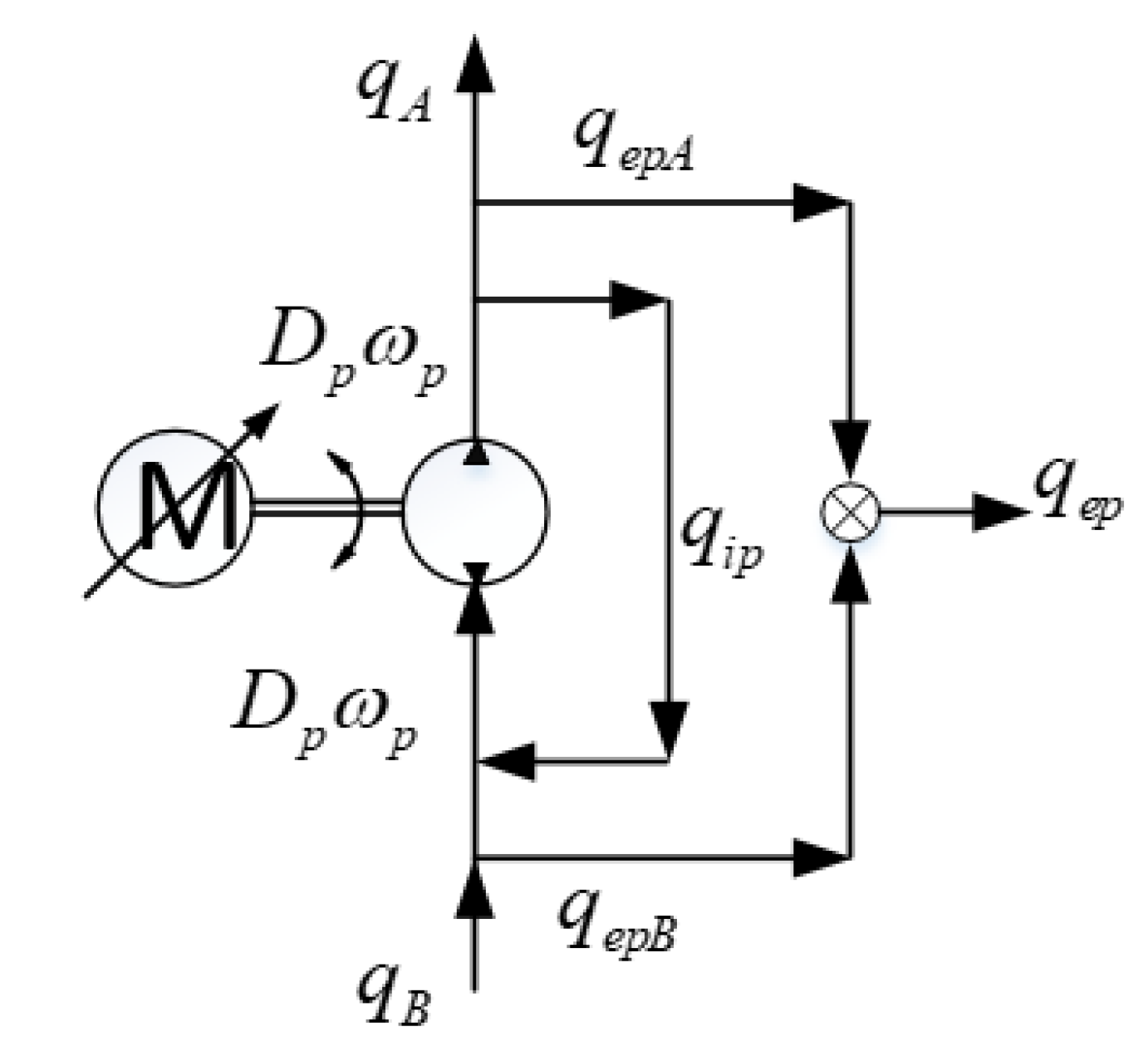
3.2. Fixed-Displacement Radial Piston Pump

Considering the factors of oil compression and internal and external leakage, the flow distribution characteristics of the quantitative pump were analyzed, as shown in Figure 2.
Assuming that the pump volume displacement of the radial piston pump is constant, the two-chamber load volume flow from the pump to the controlled hydraulic cylinder can be expressed as:
{ q A = D p ω p C i p ( p A p B ) C e p p A q B = D p ω p C i p ( p A p B ) + C e p p B
where q A and q B are the flow of system chambers A and B, D p is the pump displacement, ω p is the input speed of the pump and C i p and C e p are the internal and external leakage coefficients of the pump. p A is the pressure of system chamber A, and p B is the pressure of system chamber B, q i p = C i p ( p A p B ) , q e p A = C e p p A , q e p B = C e p p B .

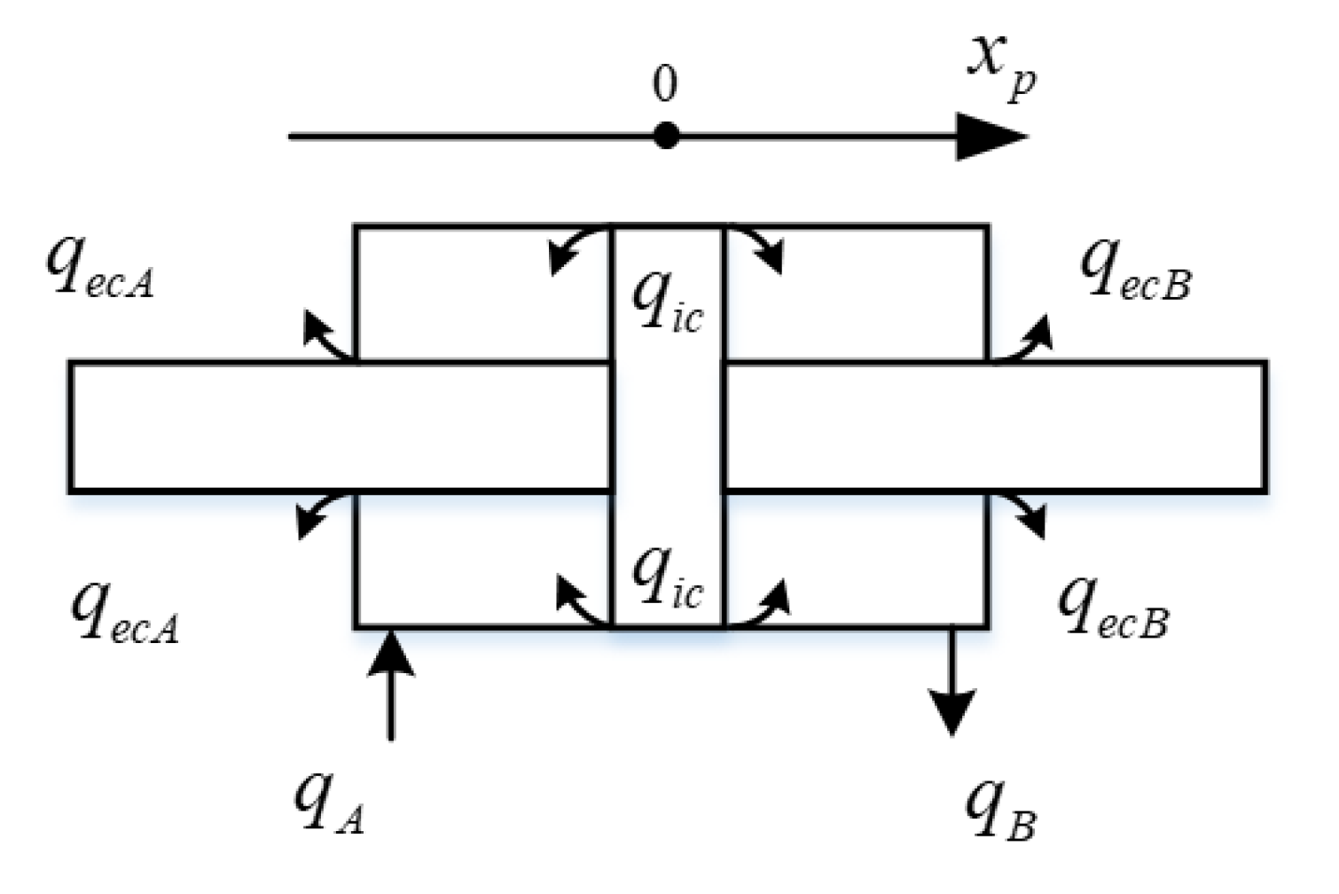
3.3. Double-Acting Symmetrical Hydraulic Cylinder

Considering load conditions, oil compression, internal and external leakage and other factors, the flow distribution characteristics of the hydraulic cylinder were analyzed, as shown in Figure 3.
The flow continuity equation of cavities A and B of the hydraulic cylinder is:
{ q A = A x ˙ p + C i c ( p A p B ) + C e c p A + V 0 + A x p β e p ˙ A q B = A x ˙ p + C i c ( p A p B ) C e c p B V 0 A x p β e p ˙ B
where A is the effective working area of the double-acting symmetrical hydraulic cylinder, x p is the displacement of the hydraulic cylinder, C i c is the internal leakage coefficient of the hydraulic cylinder, C e c is the external leakage coefficient of the hydraulic cylinder, β e is the effective volume elastic modulus and V 0 is the volume of each working chamber when the piston is in the middle position of the hydraulic cylinder, q i c = C i c ( p A p B ) , q e c A = C e c p A , q e c B = C e c p B .
When the piston position of the double-acting symmetrical cylinder is in the middle position ( x p = 0 ), the hydraulic spring stiffness is the lowest, the corresponding hydraulic system natural frequency is the lowest and the stability is the worst, so this point is selected for research.
According to Newton’s second law, the force balance equation of the hydraulic cylinder was deduced as follows:
A ( p A p B ) = m x ¨ p + B x ˙ p + K x p + F L
where m is the total mass of the piston and the load converted onto the piston, B is the viscous damping coefficient, K is the equivalent spring stiffness of the load and F L is the external interference of the system and friction force.
By applying the Laplace transform to Equations (2)–(4), respectively, we can obtain Equations (5)–(7), respectively:
{ q A ( s ) = D p ω p ( s ) C i p [ p A ( s ) p B ( s ) ] C e p p A ( s ) q B ( s ) = D p ω p ( s ) C i p [ p A ( s ) p B ( s ) ] + C e p p B ( s )
{ q A ( s ) = A s x p ( s ) + C i c [ p A ( s ) p B ( s ) ] + C e c p A ( s ) + V 0 s β e p A ( s ) q B ( s ) = A s x p ( s ) + C i c [ p A ( s ) p B ( s ) ] C e c p B ( s ) V 0 s β e p B ( s )
A [ p A ( s ) p B ( s ) ] = m s 2 x p ( s ) + B s x p ( s ) + K x p ( s ) + F L ( s )
By combining Equations (5)–(7), we obtain the block diagram of the DDVC system, as shown in Figure 4.
where F c is the actual system pressure, F c = ( p A p B ) A .
According to the analysis described in the literature [21], transforming Equations (2) and (3), we obtain Equations (8) and (9), respectively. By combining Equations (8) and (9), we obtain Equation (10).
q A + q B 2 = D p ω p C i p ( p A p B ) 1 2 C e p ( p A p B )
q A + q B 2 = A x ˙ p + C i c ( p A p B ) + 1 2 C e c ( p A p B ) + V 0 2 β e ( p ˙ A p ˙ B )
D p ω p C i p ( p A p B ) 1 2 C e p ( p A p B ) = A x ˙ p + C i c ( p A p B ) + 1 2 C e c ( p A p B ) + V 0 2 β e ( p ˙ A p ˙ B )
Equation (10) can be simplified as:
p ˙ A p ˙ B = 2 β e V 0 [ D p ω p A x ˙ p C t ( p A p B ) ]
where C t = C t c + C t p = C i c + 1 2 C e c + C i p + 1 2 C e p .
Performing Laplace transform on Equations (4) and (11), we obtain:
Δ p = D P A 2 ( m s 2 + B s + K ) ω p + S A F L V 0 m 2 β e A 2 s 3 + ( C t m A 2 + V 0 B 2 β e A 2 ) s 2 + ( 1 + C t B A 2 + K V 0 2 β e A 2 ) s + C t K A 2
Taking the motor speed ω p as the input vector of the model, then let u = ω p . The state vector of the system is defined as the piston rod displacement x p , piston rod velocity x ˙ p and pressure difference between two chambers of hydraulic cylinder p A p B . Then, the state vector can be written as:
{ x [ x 1 , x 2 , x 3 ] T = [ x p , x ˙ p , ( p A p B ) ] T y = A x 3
At this point, the state space of the nonlinear model of the DDVC electro-hydraulic servo system can be described as:
{ x ˙ 1 = x 2 x ˙ 2 = 1 m ( A x 3 B x 2 K x 1 F L ) x ˙ 3 = 2 β e V 0 ( D p u A x 2 C t x 3 ) y = A x 3
The nonlinear model of the DDVC electro-hydraulic servo system has the characteristics of strong nonlinearity and many other characteristic parameters. Consequently, it is difficult to directly solve the problem. Therefore, it is necessary to linearize the nonlinear model of the system.

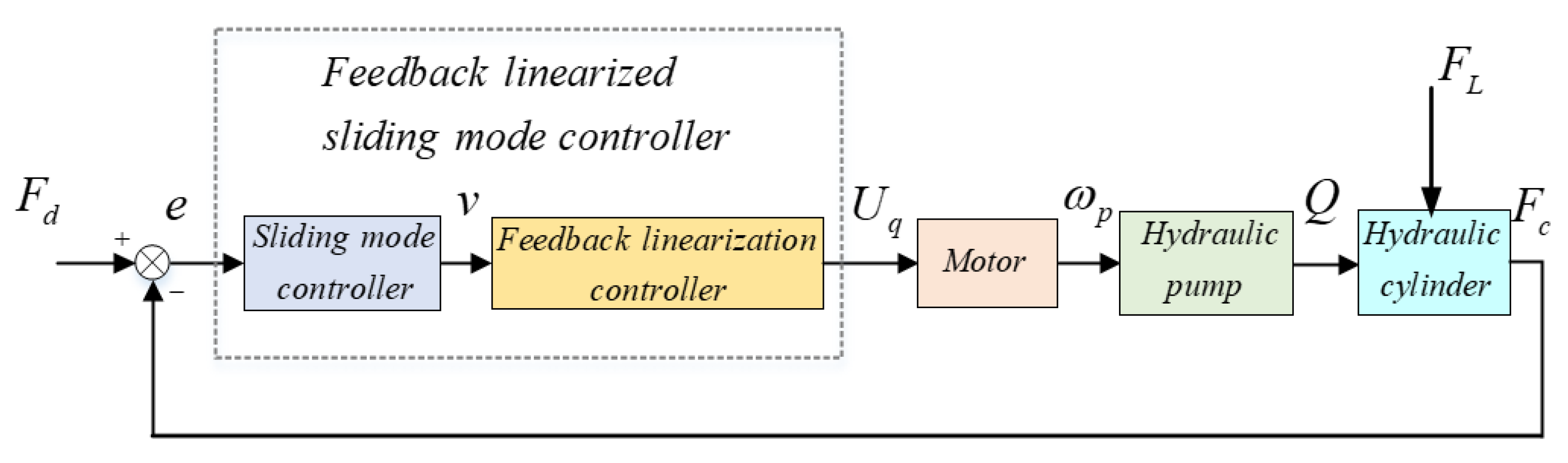
4. Feedback Linearization of Nonlinear Models

The control framework of the DDVC electro-hydraulic servo system is shown in Figure 5. The sliding mode controller with strong robustness is used to compensate for the uncertainty of the external interference in the system to improve the control precision of the system. Considering the influence of system nonlinearity, the feedback linearization controller is designed to ensure that the designed feedback linearization controller is always asymptotically stable. The input voltage of the DDVC system is obtained by the feedback linearization controller, which is then converted into the actual output speed by the servo drive unit. Then, the output of the system is controlled.
where F d is the desired system pressure, and F c is the actual system pressure that is controlled, F c = ( p A p B ) A .
Combined with Equation (14), the standard form of the affine nonlinear system corresponding to the state equation of the nonlinear mathematical model of the DDVC electro-hydraulic servo system can be written as follows:
{ x ˙ = f + g u y = h ( x ) = A x 3
where f , g is the sufficiently smooth vector field, y is the system output and h ( x ) is the system output function.
Therefore, the system nonlinear model can be rewritten as:
( x ˙ 1 x ˙ 2 x ˙ 3 ) = ( f 1 f 2 f 3 ) + ( 0 0 g 3 ) u
where f 1 = x 2 , f 2 = 1 m ( A x 3 B x 2 K x 1 F L ) , f 3 = 2 β e V 0 ( A x 2 C t x 3 ) , g 3 = 2 β e D p V 0 .
Before feedback linearization of the DDVC electro-hydraulic servo system nonlinear model, it is necessary to verify whether the model meets the conditions of feedback linearization. According to the relevant definitions, for all x near the origin, the rank of matrix
[ g   a d f g     a d f n 1 g ] is equal to system dimension n . Set { g   a d f g     a d f n 2 g } is the nonsingular involution distribution, and (f, g is the abbreviation of vector function f , g ). Then, the model meets the condition of nonlinear model state feedback linearization [22]. When the rank of the matrix is less than n , partial linearization can be achieved. However, at this time, the stability of the zero-dynamic subsystem needs to be ensured.
Setting the relative order of the system as r , its relative order can be calculated according to the following formula:
{ L g L f i h ( x ) = 0   ,   0 i < r 1   L g L f r 1 h ( x ) 0  
It can be calculated as follows:
L f 0 h ( x ) = A x 3
L g L f 0 h ( x ) = A g 3 = 2 A β e D p V 0 0
L f h ( x ) = 2 A β e V 0 ( A x 2 C t x 3 )
Combining Equations (17) and (19), it can be known that the relative degree of the system is 1.
According to the input–output feedback linearization method, the transformation relationship between the new state variable and the original state variable is constructed as follows:
{ z 1 = h ( x ) = A x 3 y = z 1
Then, the original state equation of the nonlinear system can be transformed into the state equation in the linear space:
{ z ˙ 1 = v y = z 1
where v is the control quantity of the linear system in the new coordinate system v = α ( x ) + β ( x ) u , α ( x ) = 2 A β e V 0 ( A x 2 C t x 3 ) , β ( x ) = 2 A β e D p V 0 .
The inverse coordinate transformation of the control quantity v of the linear system can obtain the control quantity u of the nonlinear system under the original coordinate, as shown in Equation (23).
u = ( v α ( x ) ) / β ( x )

5. Sliding Mode Controller Design

There is no accurate nonlinear system model for feedback linearization. Therefore, when the load, pressure and hydraulic oil viscosity of the DDVC electro-hydraulic servo system change, the pressure tracking accuracy of the system will be affected, so it is necessary to introduce a strong robust control algorithm to solve this problem. Sliding mode control is a kind of variable structure control method that has strong adaptability and robustness to system parameter changes and external disturbances. Thus, sliding mode control has been widely used in various fields. The force tracking error is defined as:
e = z 1 z d
where z d is the desired system pressure Fd, and z 1 is the actual system pressure F c .
According to the equation of state in linear space, the state equation of system error can be written as:
e ˙ = v z ˙ d
The sliding mode surface function is defined as:
s = e
If we take its derivative, we can obtain the result:
s ˙ = v z ˙ d
To ensure the quality of the normal movement stage, take the constant speed approaching rate:
s ˙ = k sgn ( s ) , k > 0
According to the first two formulae, the output of sliding mode control is:
v = z ˙ d k sgn ( s )
Constructing Lyapunov function: V ( s ) = s 2 / 2 , when s = 0 , V ( s ) = 0 . When s 0 , V ( s ) > 0 . Thus, V ( s ) is a positive definite function. The derivation of the equation is obtained:
V ˙ ( s ) = s s ˙ = s ( k sgn ( s ) ) = k | s | < 0
As can be seen from the above equation, V ˙ < 0 . The sliding mode control system under the new coordinates meets the Lyapunov stability theory conditions, thus ensuring that the system is asymptotically stable. It is worth mentioning that, to avoid sliding mode chattering, the use of symbol function sgn ( * ) in simulation and practical application will inevitably lead to chattering of the final output. Therefore, the continuous saturation function sat ( * ) is used to replace the symbol function:
sat ( * ) = { 1 ,   if ( * 1 ) * ,   if ( 1 < * < 1 ) 1 ,   if ( * 1 )
According to the above equation, the control quantity u of the nonlinear system in the original coordinate is:
u = z ˙ d k sat ( s ) 2 A β e V 0 ( A x 2 C t x 3 ) 2 A β e D p V 0
In combination with Equation (1), the pump speed u ( ω p ) can be controlled by software programming controls the voltage u c input to the system so as to control the system pressure z 1 ( F c ), and the value of ω p can be transmitted through the CAN bus.

6. Experimental Study

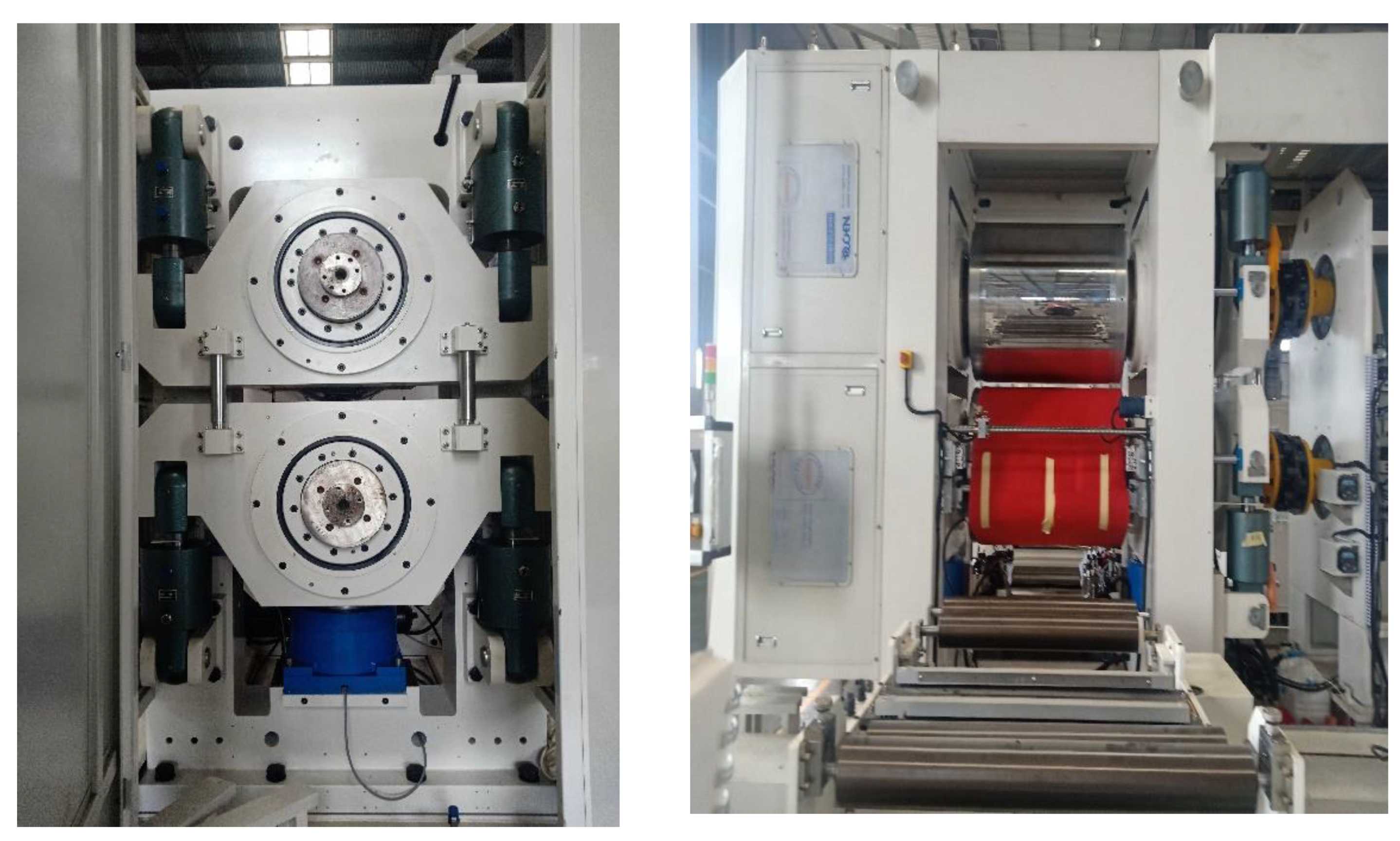
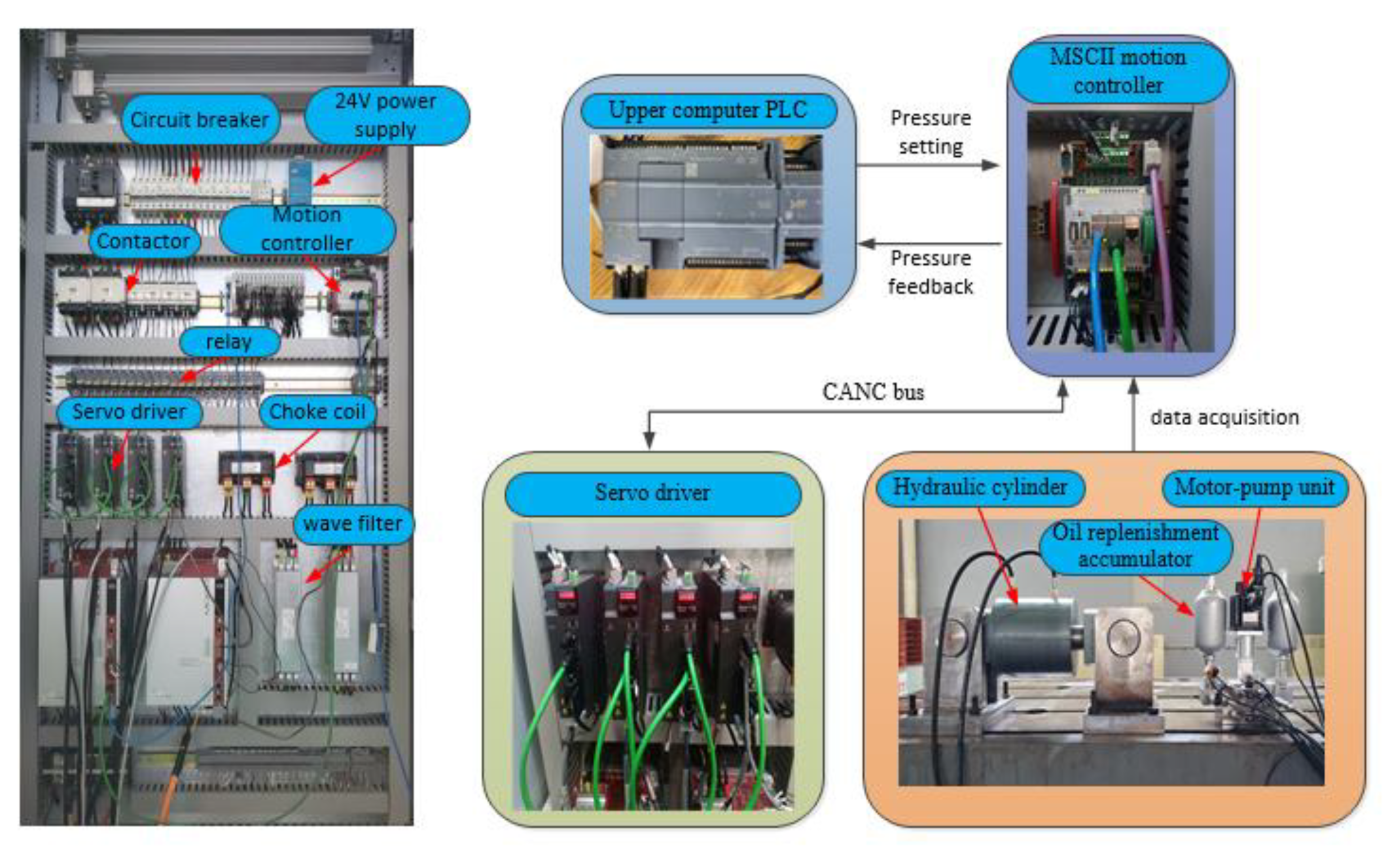
6.1. Electro-Hydraulic Servo System Test Bench Design

The experiment is based on the enterprise R&D project “pump control servo system of lithium battery pole rolling mill”, and the rolling mill equipment structure is shown in Figure 6. A DDCV electro-hydraulic servo pressure control test platform was built. The detailed parameter values of hydraulic pump displacement, hydraulic cylinder working volume, piston effective area and so on are shown in Table 1. The feedback-linearized sliding mode control algorithm proposed in this paper was verified using the DDVC electro-hydraulic servo system experimental platform. The electrical schematic diagram and hydraulic valve block were designed according to the actual process requirements and hardware models of the system. Each component was installed and fixed in the electric control cabinet according to the schematic diagram, and the cable was connected. The overall hardware composition of the electric control cabinet and hydraulic system after installation is shown in Figure 7. The experimental platform was mainly composed of upper-computer PLC, MOOG MSCII motion controller, servo driver, the motor-pump unit, functional valve block, working and loading hydraulic cylinder and electronic control cabinet operating platform. The cylinder body and cylinder rod of the hydraulic cylinder are fixed on the mechanical tooling, which is fixed on the iron platform. Whether the cylinder rod is extended or retracted, it will be subjected to the reaction force of the tooling, resulting in the load force.
The upper-computer PLC sends the control command of desired pressure F d to the MSCII motion controller through the analog quantity. At the same time, the controller collects the pressure, displacement, temperature and other information in the hydraulic system in real time through the sensors, obtains the pressure control output signal in combination with the high-performance control algorithm program of pressure control and sends the output signal to the servo driver through the communication mode of the CAN bus, then the motor-pump unit can accurately control the system pressure F c in the hydraulic system, which forms a high-performance pressure closed-loop control.

6.2. Experiment Content and Result Analysis

The PID controller has been widely used in electro-hydraulic servo control due to its simple structure and strong robustness. Therefore, the PID controller can be selected to compare with the feedback-linearized sliding mode controller. The PID controller has three basic control rules: proportional (P) control, integral (I) control and differential (D) control. Proportional gain P can affect the response speed and steady-state accuracy of the controller. The integral gain I can affect the controller’s ability to eliminate steady-state pressure errors of the system. Differential gain D can affect the ability of the system to resist pressure error change. The parameters of the PID controller are adjusted by a trial-and-error method, and gain P is 52.5, gain I is 5 and gain D is 0.
The specific implementation method of the experiment is as follows: First, the feedback linearization sliding mode control algorithm is built by using Simulink software and downloaded to MOOG MACS axis control software. The editing system logic control program in the software is used. The desired pressure signal instruction F d is given by the software program. Step response signal and sinusoidal response signal are used here. The PID controller and feedback linearization controller are used to control the system pressure F c . The pressure signal of the pressure sensor is collected and analyzed in real time, and the actual pressure F c of the system is obtained. The control results of the PID controller and feedback linearization controller on system pressure are obtained, respectively. The experimental results are compared to verify the pressure control accuracy and steady-state response speed of the feedback linearization control algorithm.

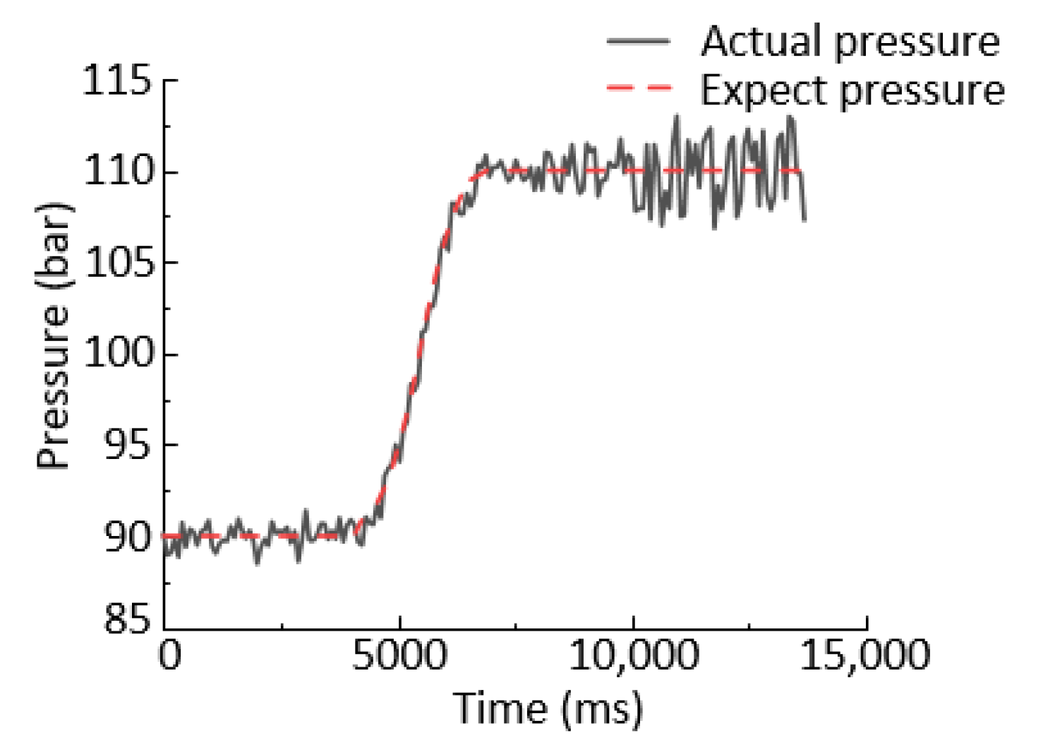
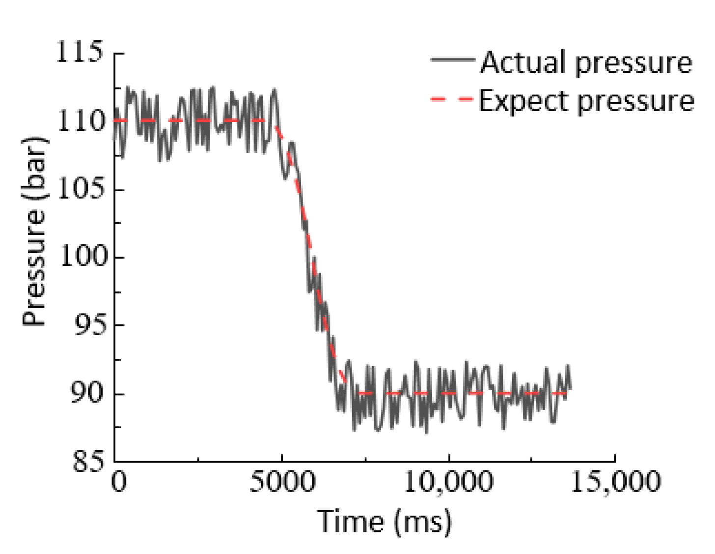
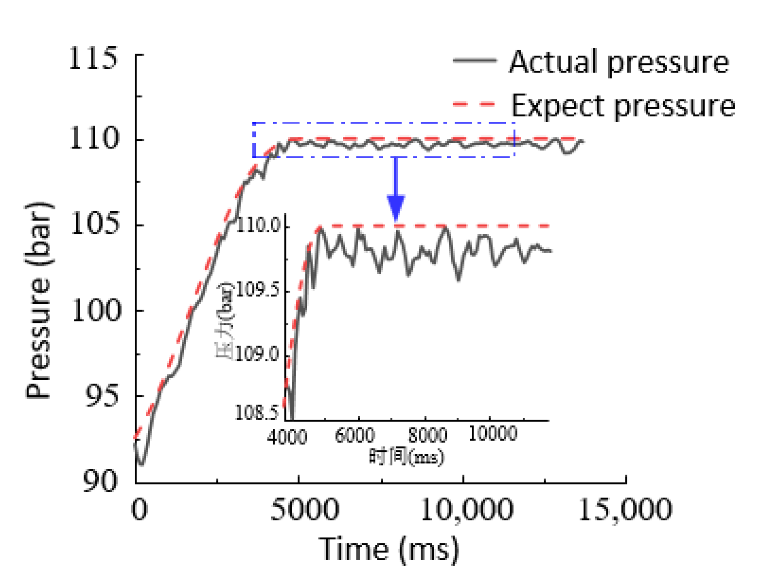
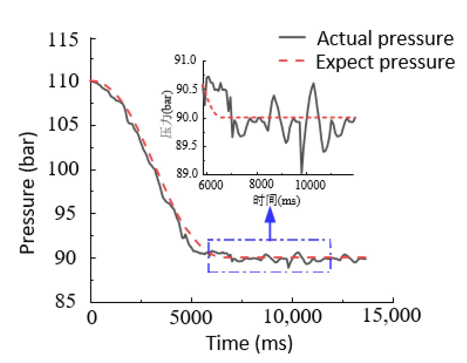
6.2.1. Step Signal Response Experiment

When the step signal was given from 90 bar to 110 bar and from 110 bar to 90 bar, the classical PID control method in industrial control (marked by PID) was used. The system pressure curves are shown in Figure 8 and Figure 9. The feedback-linearized sliding mode control method was adopted, and the system pressure curves are shown in Figure 10 and Figure 11.
For the convenience of analysis, the actual pressure curve and the expected pressure curve were displayed on the same interface. Through experimental research, the step response curves of the pressure control system under the PID controller and the feedback-linearized sliding mode controller were analyzed, and the following conclusions were drawn: (1) The traditional PID controller makes it difficult to adjust the optimal parameters, and the steady-state error is relatively large, reaching errors as high as 3 bar. (2) The feedback-linearized sliding mode controller has no obvious overshooting when it reaches the steady state, and the pressure accuracy can be controlled within 0.5 bar, and the accuracy is improved by about 2.5 bar. It can be concluded that the control method has a clear effect on improving the control performance of the DDVC electro-hydraulic servo pressure control system, and the steady-state error is small.

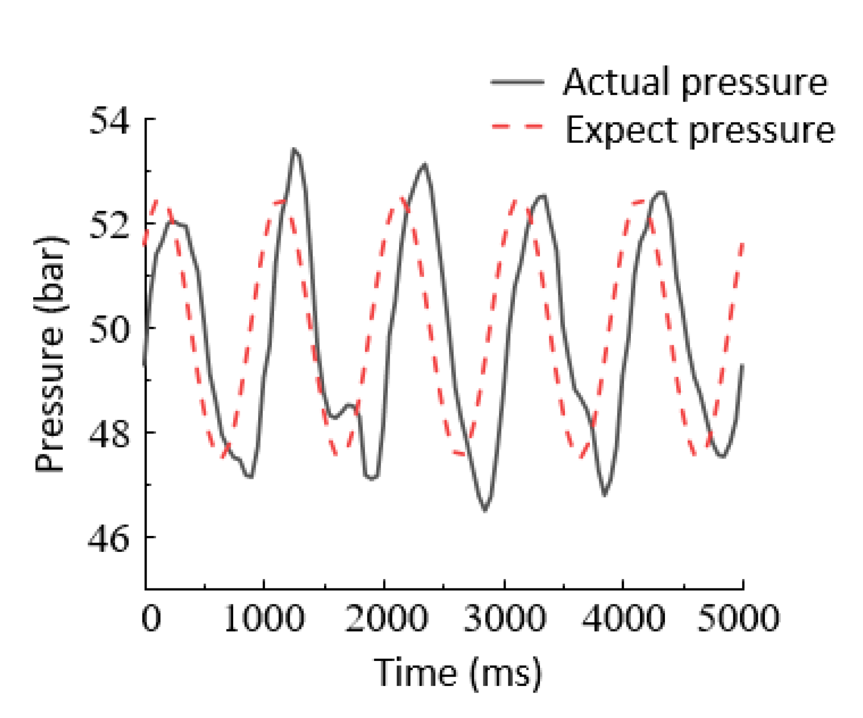
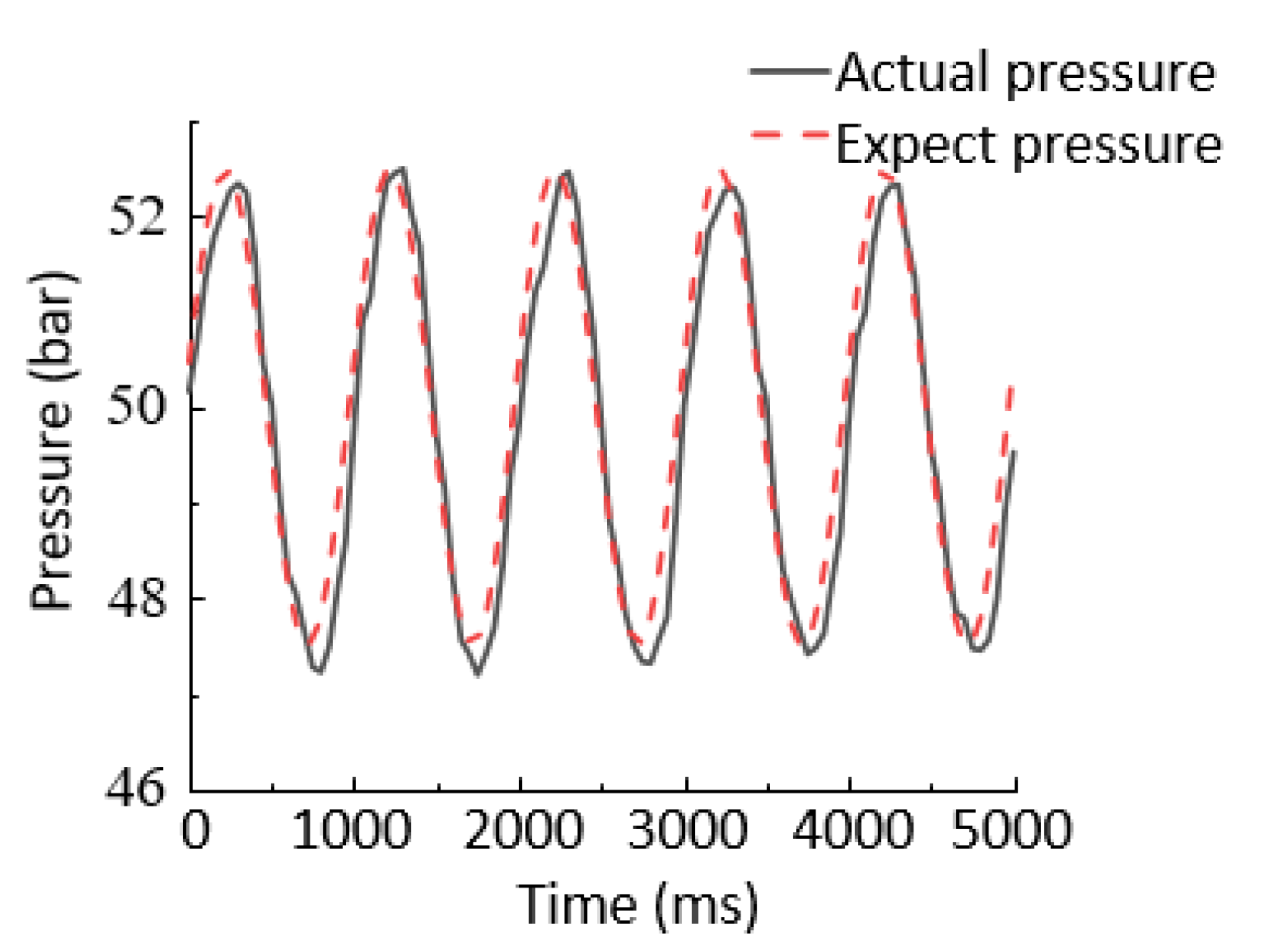
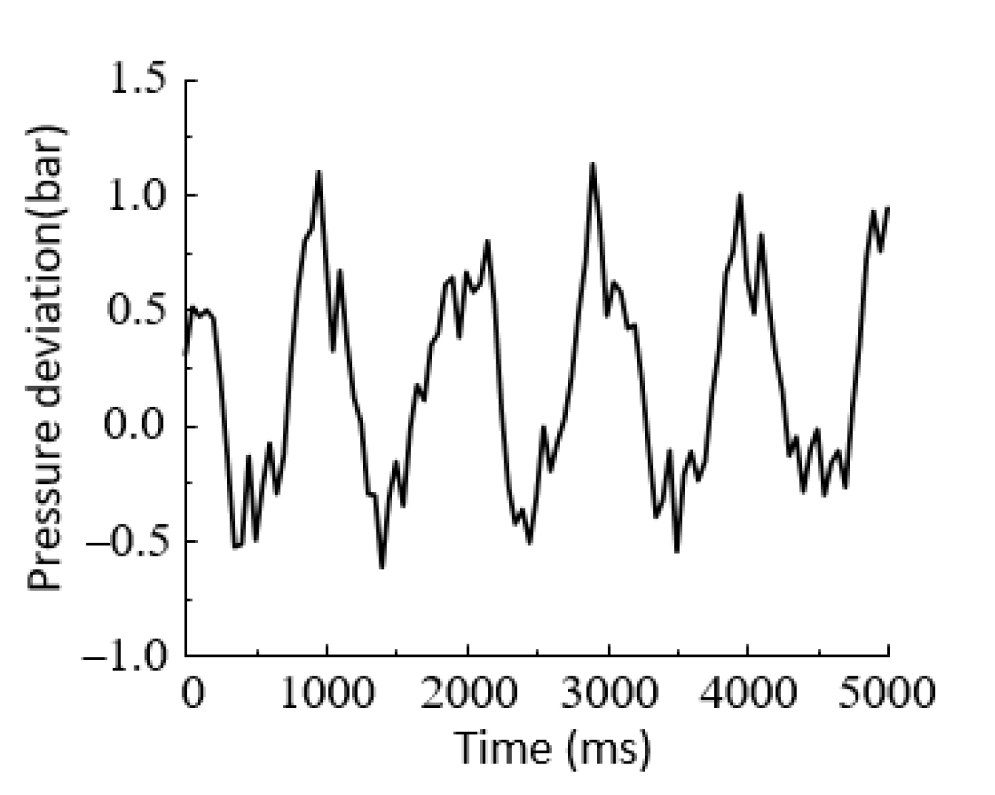
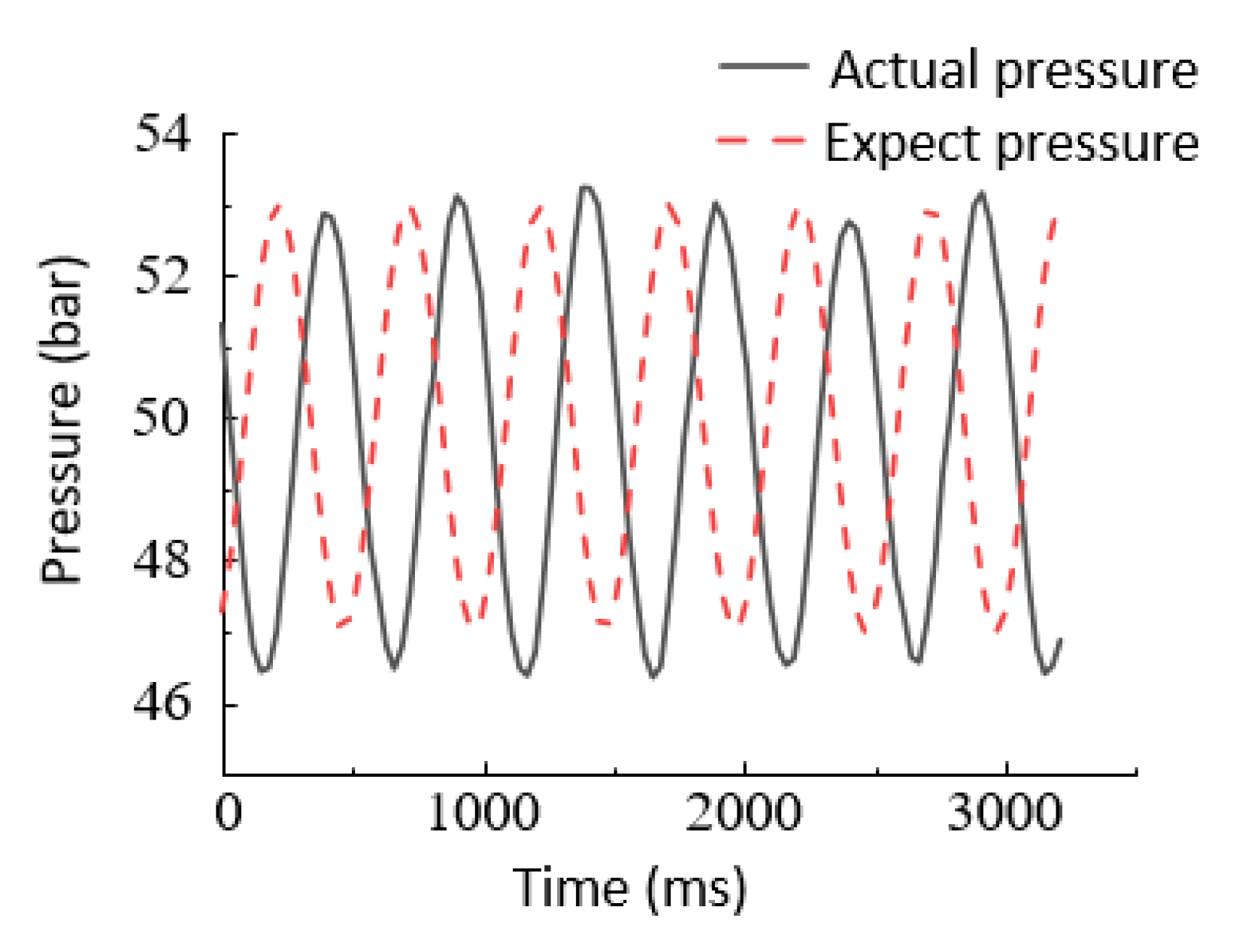
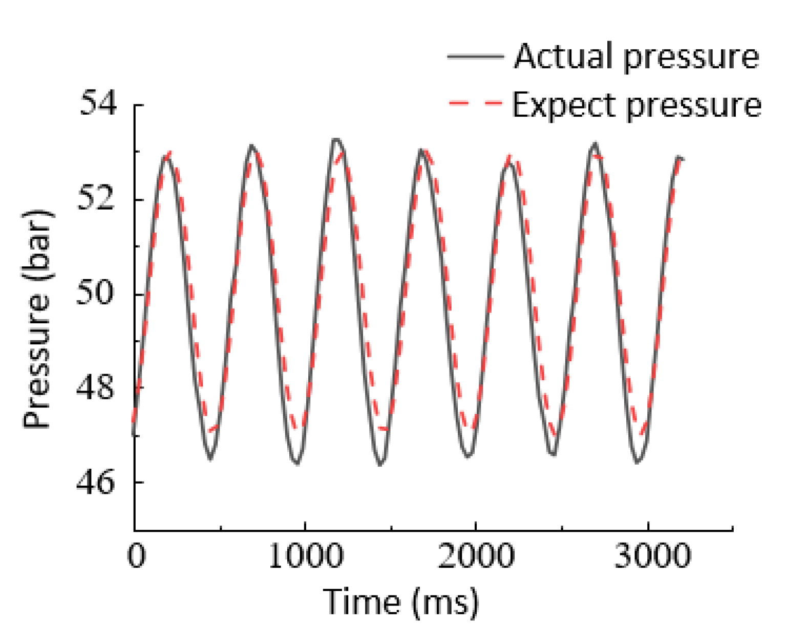
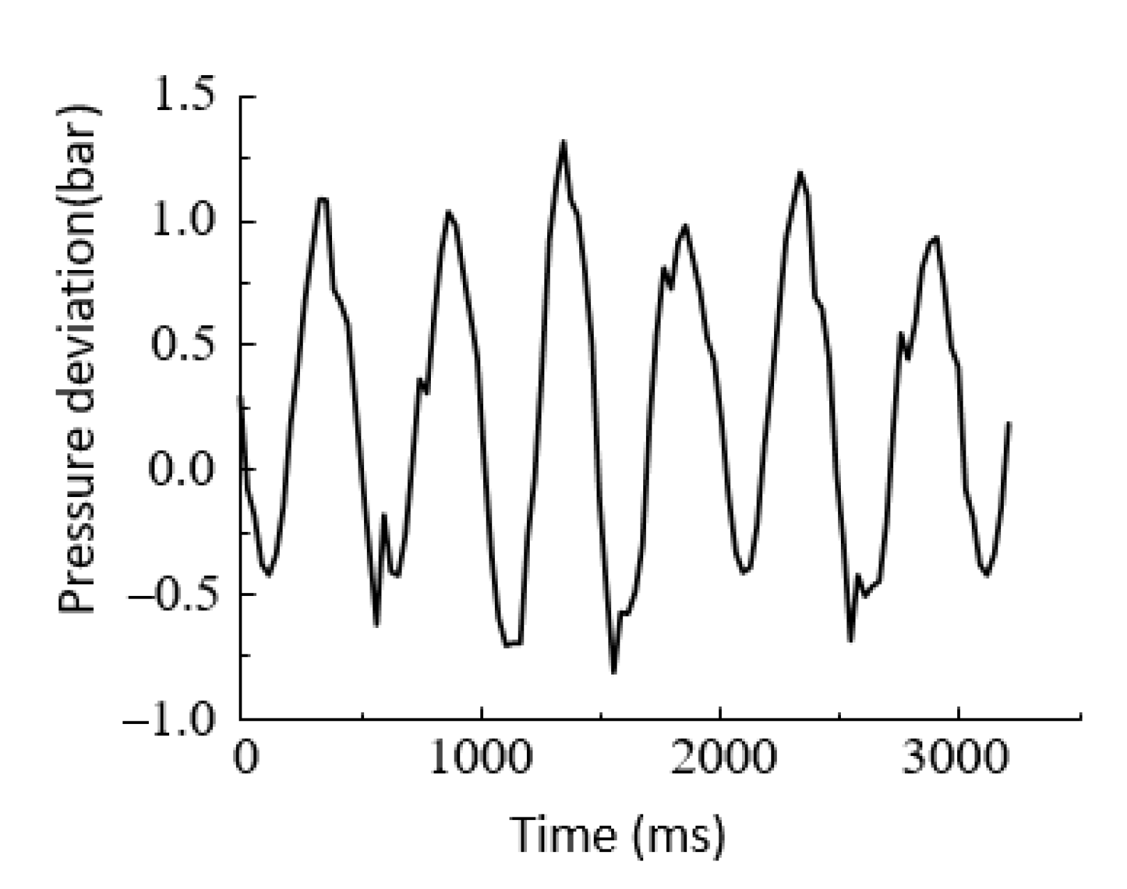
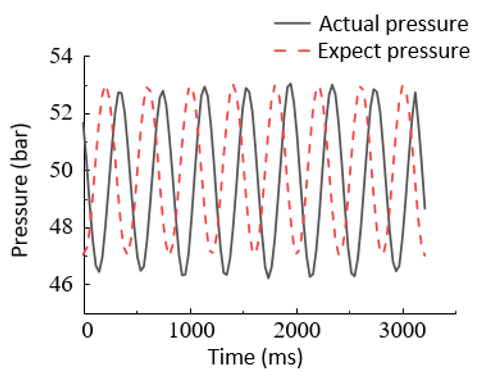
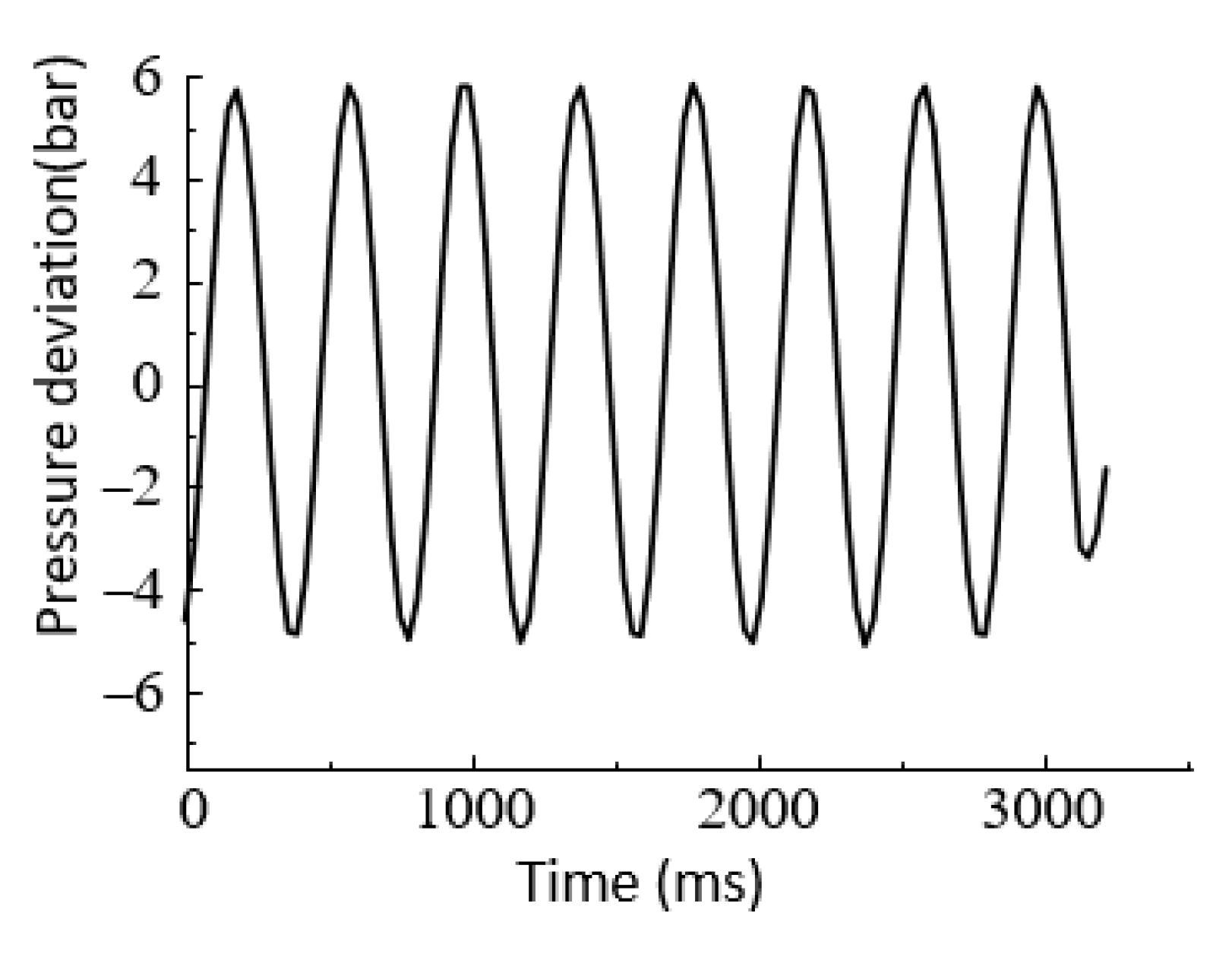
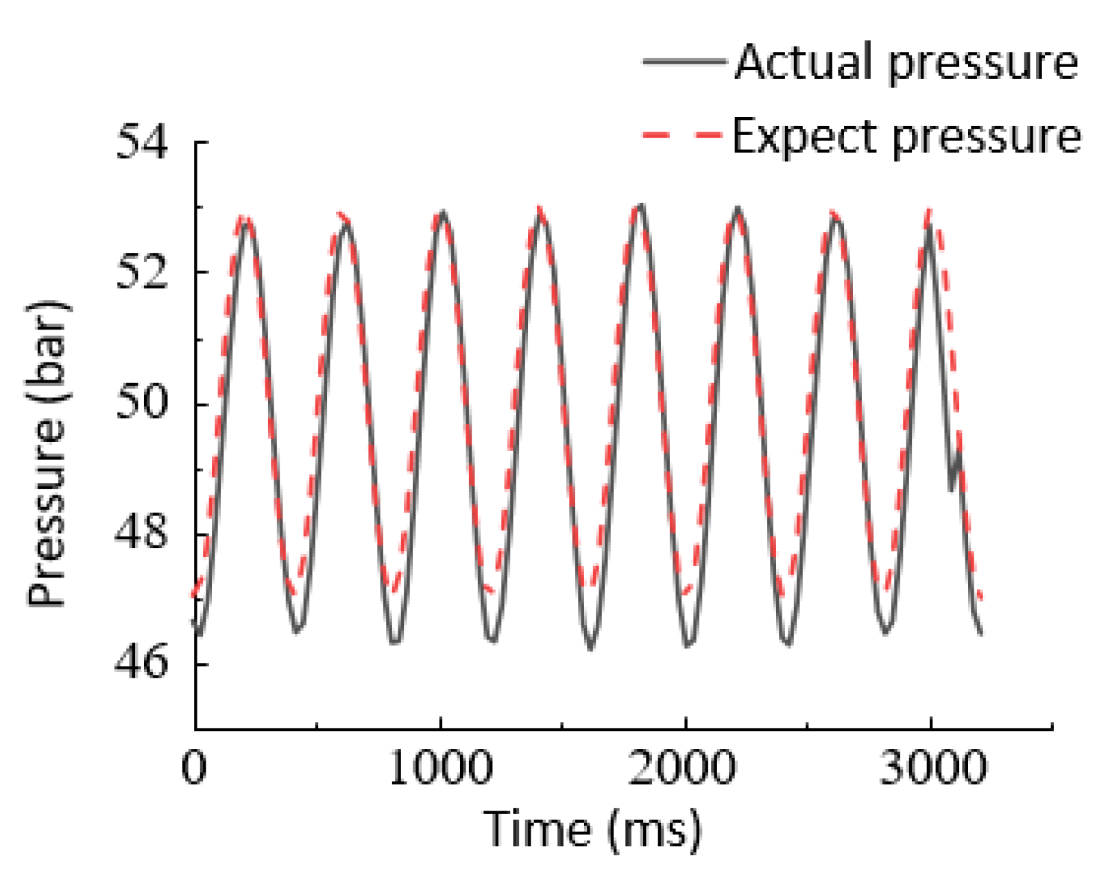
6.2.2. Sinusoidal Response Experiments

Based on the given sinusoidal signals of the DDVC electro-hydraulic servo pressure control system at different frequencies and the same amplitude, the variation of the tracking curves was observed. Figure 12, Figure 13, Figure 14 and Figure 15 show the sinusoidal response following curves of the traditional PID control and feedback-linearized sliding mode control under a sinusoidal signal with a frequency of 1 Hz and an amplitude of 5 bar. The system had certain overshooting and hysteretic phenomena. Under the traditional PID control, the pressure deviation was relatively large (approximately 4 bar). Under the feedback-linearized sliding mode control, the pressure deviation was small (approximately 0.5 bar), and the tracking curve was relatively complete.
Figure 16, Figure 17, Figure 18 and Figure 19 show the sinusoidal response following curves of the traditional PID control and feedback-linearized sliding mode control under a sinusoidal signal with a frequency of 2 Hz and an amplitude of 5 bar. Under traditional PID control, pressure overrun and hysteresis phenomena were more prominent, and the steady-state error was relatively large (approximately 5 bar). Under the feedback-linearized sliding mode control, the overshoot of the system was small, and the expected pressure curve can be easily followed. The steady-state error was small (approximately 0.7 bar).
Figure 20, Figure 21, Figure 22 and Figure 23 show the sinusoidal response following curves of the traditional PID control and feedback-linearized sliding mode control under a sinusoidal signal with a frequency of 2.5 Hz and an amplitude of 5 bar. The experimental curve in Figure 20 shows that, under traditional PID control, the lag of pressure following was obvious. Furthermore, the error, as shown in Figure 21, was larger than that when the frequency was 1 Hz and 2 Hz, reaching about 6 bar. However, as shown in Figure 22, when the feedback-linearized sliding mode control method was adopted, the system overrun and hysteresis phenomena were significantly improved, and the expected pressure curve can be easily followed. As can be seen from Figure 23, the error was significantly reduced and around 1bar, meeting the control requirements.
By comparing the experiments, it can be concluded that the feedback-linearized sliding mode control method is clearly better than the traditional linear PID controller. This is mainly because, when tracking a given low-frequency signal, the electro-hydraulic servo system mainly presents the velocity integral characteristic. On the other hand, the feedback-linearized sliding mode control contains the active velocity feedforward compensation link, so it can obtain better control performance. In addition, the feedback-linearized sliding mode control cancels the main nonlinear characteristics of the hydraulic system through the model compensation term, so the steady-state output pressure accuracy is less than 1 bar.

7. Conclusions

Aiming to solve the high-precision pressure control problem of the DDVC electro-hydraulic servo system, a feedback-linearized sliding mode control strategy was proposed. The following conclusions were obtained:
(1)
The mathematical model of the DDVC electro-hydraulic servo system was established, and the pressure output transfer function of the system was deduced.
(2)
Considering the nonlinearity of the system, a feedback-linearized sliding mode control strategy was proposed to deal with the nonlinear components of the system and convert the dynamic performance of the nonlinear system to linear characteristics to optimize the control performance of the system. The linearized sliding mode control strategy was applied to the DDVC system for high-precision pressure control.
(3)
The experimental analysis shows that the proposed controller can effectively improve the pressure output accuracy of the electro-hydraulic servo pressure control system and improve the dynamic response characteristics of the system compared with the PID controller. However, some idealized models of the system are simplified. To improve the nonlinear accuracy of the system, the nonlinear model can be further refined.

Author Contributions

Conceptualization, G.Y. and P.J.; methodology, G.C.; experiment and analysis, G.Y. and C.J.; software, P.J.; investigation, G.C.; writing—original draft preparation, W.C. and P.J.; writing—review and editing, G.Y. and H.L.; project administration, C.A.; funding acquisition, C.A. All authors have read and agreed to the published version of the manuscript.

Funding

This research was supported by the Key R&D Projects in Hebei Province (No. 20314402D), the Key Project of Science and Technology Research in Hebei Province (No. ZD2020166), the Key Project of Science and Technology Research in Hebei Province (No. ZD2021340) and the General Project of Natural Science Foundation in Xinjiang Uygur Autonomous Region (No. 2021D01A63).

Institutional Review Board Statement

Not applicable.

Informed Consent Statement

Not applicable.

Data Availability Statement

Not applicable.

Conflicts of Interest

The authors declare no conflict of interest.

References

  1. Bo, W.; Yunxiao, H.; Long, Q.; Xiangyu, W.; Lei, G.; Bin, Z. Research on characteristics of electro hydraulic servo system controlled by separate cavity independent variable speed pump. J. Mech. Eng. 2020, 56, 235–243. [Google Scholar] [CrossRef]
  2. Penghui, Z. Research on Position Control of Transferable Vane Electro-Hydraulic Servo Closed Pump Control System. Master’s Thesis, Yanshan University, Qinhuangdao, China, 2020. [Google Scholar]
  3. Bing, Y. Study on Thermal Balance of Direct-Drive Volumetric Control Electro-Hydraulic Servo System. Master’s Thesis, Yanshan University, Qinhuangdao, China, 2020. [Google Scholar]
  4. Helbig, A. Injection moulding machine with electric-hydrostatic drives. In Proceedings of the 3. International Fluid Power Conference (3. IFK), Aachen, Germany, 5–6 March 2002; pp. 67–82. [Google Scholar]
  5. Sedrak, D. Closed-loop electronic valuing and the application of variable voltage variable frequency in hydraulics. Elev. World 1999, 47, 66–72. [Google Scholar]
  6. Lee, S.R.; Hong, Y.S. A dual EHA system for the improvement of position control performance via active load compensation. Int. J. Precis. Eng. Manuf. 2017, 18, 937–944. [Google Scholar] [CrossRef]
  7. Ahn, K.K.; Nam, C.; Jin, M. Adaptive backstepping control of an electro-hydraulic actuator. IEEE ASME Trans. Mechatron. 2014, 19, 987–995. [Google Scholar] [CrossRef]
  8. Zhen, Z.; Haijun, L.; Xiaoyan, Q.; Zhen, Z. Robust feedback linearization control of electro-hydraulic position servo system. Mach. Tools Hydraul. 2016, 44, 148–152. [Google Scholar]
  9. Juni, H. Development and application of electro-hydraulic servo system. Mach. Tool Hydraul. 2012, 40, 15–18. [Google Scholar]
  10. Ruidong, L. Analysis and Compensation Method for Position and Force Control Characteristics of Electrohydrostatic System. Master’s Thesis, Yanshan University, Qinhuangdao, China, 2020. [Google Scholar]
  11. Song, B.; Lee, D.; Park, S.Y.; Baek, Y.S. Design and performance of nonlinear control for an electro-hydraulic actuator considering a wearable robot. Processes 2019, 7, 389. [Google Scholar] [CrossRef] [Green Version]
  12. Helian, B.; Chen, Z.; Yao, B. Precision motion control of a servomotor-pump direct-drive electrohydraulic system with a nonlinear pump flow mapping. IEEE Trans. Ind. Electron. 2020, 67, 8638–8648. [Google Scholar] [CrossRef]
  13. Kim, J.H.; Hong, Y.S. Robust internal-loop compensation of pump velocity controller for precise force control of an electro-hydrostatic actuator. J. Drive Control 2018, 15, 55–60. [Google Scholar]
  14. Kim, J.H.; Hong, Y.S. Improvement of back drivability of a force-controlled EHA by introducing bypass flow control. Int. J. Precis. Eng. Manuf. 2020, 21, 819–830. [Google Scholar] [CrossRef]
  15. Komsta, J.; Adamy, J.; Antoszkiewicz, P. Input-output linearization and integral sliding mode disturbance compensation for electro-hydraulic drives. In Proceedings of the 2010 11th International Workshop on Variable Structure Systems (VSS), Mexico City, Mexico, 26–28 June 2010; pp. 446–451. [Google Scholar] [CrossRef]
  16. Koch, S.; Reichhartinger, M. Observer-based sliding mode control of hydraulic cylinders in the presence of unknown load forces. e i Elektrotechnik Inf. 2016, 133, 253–260. [Google Scholar] [CrossRef] [Green Version]
  17. Huang, J.; An, H.; Ma, H.; Wei, Q.; Wang, J. Electro-hydraulic servo force control of foot robot based on feedback linearization sliding mode control. In Proceedings of the 2018 13th World Congress on Intelligent Control and Automation (WCICA), Changsha, China, 4–8 July2018; pp. 1441–1445. [Google Scholar]
  18. Lu, X.; Wei, H.; Zhuoping, Y.; Haocheng, L. Accurate hydraulic pressure control of master cylinder of integrated electronic hydraulic braking system considering key nonlinear characteristics. J. Mech. Eng. 2019, 55, 117–126. [Google Scholar] [CrossRef]
  19. Kou, F.; Du, J.; Wang, Z.; Li, D.; Xu, J. Nonlinear modeling and coordinate optimization of a semi-active energy regenerative suspension with an electro-hydraulic actuator. Algorithms 2018, 11, 12. [Google Scholar] [CrossRef] [Green Version]
  20. Zhu, Y.; Tang, S.; Wang, C.; Jiang, W.; Zhao, J.; Li, G. Absolute stability condition derivation for position closed-loop system in hydraulic automatic gauge control. Processes 2019, 7, 766. [Google Scholar] [CrossRef] [Green Version]
  21. Wang, C. Hydraulic Control System; China Machine Press: Beijing, China, 2012; pp. 41–42. [Google Scholar]
  22. Zhang, Z.; Li, H.; Zhu, D. EHA feedback linearization optimal sliding mode surface double fuzzy sliding mode control. J. Beijing Univ. Aeronaut. Astronaut. 2016, 42, 1398–1405. [Google Scholar]
Figure 1. Schematic diagram of the DDVC electro-hydraulic servo system. 1: servo motor, 2: positive displacement pump, 3: temperature sensor, 4: pressure relay, 5: pressure joint, 6: check valve, 7: oil replenishment accumulator, 8: relief valve, 9: pressure sensor, 10: unloading valve, 11: symmetrical hydraulic cylinder.
Processes 09 01676 g001
Figure 2. Flow distribution of hydraulic pump.
Processes 09 01676 g002
Figure 3. Hydraulic cylinder flow distribution.
Processes 09 01676 g003
Figure 4. Block diagram of the DDVC system.
Processes 09 01676 g004
Figure 5. Control block diagram of the DDVC electro-hydraulic servo system.
Processes 09 01676 g005
Figure 6. Rolling mill equipment structure.
Processes 09 01676 g006
Figure 7. Overall hardware structure of the system.
Processes 09 01676 g007
Figure 8. PID controller step rise curve.
Processes 09 01676 g008
Figure 9. PID controller step drop change curve.
Processes 09 01676 g009
Figure 10. Feedback-linearized step rise curve of the sliding mode controller.
Processes 09 01676 g010
Figure 11. Feedback-linearized step drop curve of the sliding mode controller.
Processes 09 01676 g011
Figure 12. PID control response curve at 1 Hz.
Processes 09 01676 g012
Figure 13. PID control error change curve at 1 Hz.
Processes 09 01676 g013
Figure 14. Feedback-linearized sliding mode control response curve at 1 Hz.
Processes 09 01676 g014
Figure 15. Feedback-linearized sliding mode control error change curve at 1 Hz.
Processes 09 01676 g015
Figure 16. PID control response curve at 2 Hz.
Processes 09 01676 g016
Figure 17. PID control error change curve at 2 Hz.
Processes 09 01676 g017
Figure 18. Feedback-linearized sliding mode control response curve at 2 Hz.
Processes 09 01676 g018
Figure 19. Feedback-linearized sliding mode control error change curve at 2 Hz.
Processes 09 01676 g019
Figure 20. PID control response curve at 2.5 Hz.
Processes 09 01676 g020
Figure 21. PID control error change curve at 2.5 Hz.
Processes 09 01676 g021
Figure 22. Feedback-linearized sliding mode control response curve at 2.5 Hz.
Processes 09 01676 g022
Figure 23. Feedback-linearized sliding mode control error change curve at 2.5 Hz.
Processes 09 01676 g023
Table 1. Main parameters of the experimental platform.
ParameterPhysical MeaningValue
C i p ((m3/s)/Pa)Internal leakage coefficient of pump1 × 10−13
Cep ((m3/s)/Pa)External leakage coefficient of pump1 × 10−13
D (mL/r)pump delivery0.8
P P (kW)Rated power of pump1
Pm (MPa)Maximum working pressure of pump21
Cic ((m3/s)/Pa)Internal leakage coefficient of hydraulic cylinder1 × 10−13
K v p (N/(m/s))Damping coefficient of piston150
k Gas polytropic coefficient1.3
F s (N)Sliding static friction25
Fc (N)Sliding Coulomb friction15
V 0 (mL)Initial volume of one side of hydraulic cylinder450
β e (N/m2)Oil elastic modulus6.5 × 108
A (cm2)Effective area of piston71
m (Kg)Load conversion quality2000
V g i (mL)Initial gas volume of accumulator200
Pai (MPa)Initial pressure of accumulator3
V a i (mL)Initial oil volume of accumulator200
u (V)Rated voltage of servo motor220
P m (kW)Rated power of servo motor1
n (r/min)Rated speed of servo motor3000
T e (N·m)Servo motor torque3.18
J (kg·m2)Moment of inertia of servo motor2.65 × 10−4
Publisher’s Note: MDPI stays neutral with regard to jurisdictional claims in published maps and institutional affiliations.

