1. Introduction
The industrial refrigeration sector is growing rapidly and its impacts on human life and within different industries cannot be underestimated. It is anticipated that the value of the global industrial refrigeration sector will grow to around
$25 billion by 2025 [
1]. Growing demand and interest for developing innovative refrigeration systems, and increasing support from the government to improve the cold chain infrastructure, are the key drivers of industrial refrigeration sector growth [
2]. However, the rapid growth of the refrigeration sector has caused some challenges due to the substantial energy consumption of refrigeration systems and negative environmental impacts of many refrigerants, such as their high global warming potential (GWP) [
3,
4,
5]. Therefore, enhancing the performance of refrigeration systems and using low refrigerants with low GWP are two major routes towards mitigating the environmental impacts of refrigeration systems and providing significant carbon savings [
6].
Cascade vapor compression refrigeration systems have been considered the most appealing type of refrigeration systems, especially for low-temperature applications where other refrigeration systems offer a low coefficient of performance (COP) [
7,
8]. A cascade refrigeration system comprises two separate refrigeration cycles thermally connected through a heat exchanger, called a cascade heat exchanger. A substantial number of studies have been presented in the literature regarding the potential performance improvement of cascade refrigeration cycles via several means and the selection of a more suitable refrigerant pair to achieve energy-saving and address environmental concerns.
For example, Bingming et al. [
9] examined the performance of NH
3/CO
2 cascade refrigeration system using an experimental study. They conducted a parametric study to investigate the performance of several parameters on the system performance. The cascade system performance was compared with a two-stage NH
3 system and a single-stage NH
3 system with and without an economizer. The results showed the superiority of the cascade cycle for an evaporating temperature of lower than 40 °C. Yari and Mahmoudi [
10], proposed two CO
2 cascade refrigeration cycles and evaluated their performance using a thermodynamic model. While both cycles consisted of an ejector-expansion transcritical cycle as the topping cycle and a sub-critical CO
2 cycle as the bottoming cycle, in one of the cycles, a supercritical CO
2 power cycle was used to recover the waste heat from the gas cooler of the topping cycle.
The results of this study showed that both cycles showed a COP improvement over a conventional cascade cycle and the cycle that used supercritical CO
2 power cycle for waste energy recovery had a better performance. Sarkar et al. [
11] performed a thermodynamic analysis and optimization to identify the most suitable refrigerant pairs for a cascade refrigeration system. They evaluated the suitability of eight refrigerants and 56 possible combinations of refrigerant pairs using COP as a criterion. They found that propane-ammonia and propylene-ammonia are the best refrigerant pairs for higher evaporator temperatures and ethane-propylene is the best refrigerant pair for lower evaporator temperatures.
Aghazadeh Dokandari et al. [
12] evaluated the use of ejectors in a cascade refrigeration cycle that used ammonia-carbon dioxide (NH
3-CO
2) refrigerant pair from a thermodynamic perspective. It was shown that using ejectors in the cycle can improve the COP of the cascade refrigeration cycle up to 7%. The results showed that the proposed ejector-based cascade refrigeration cycle has a promising application. Yilmaz et al. [
13] carried out a thermodynamic analysis to evaluate the performance of a cascade refrigeration cycle that used CO2-R404a refrigerant pair. The authors performed a parametric study to identify the optimum operating conditions of the cycle and maximize the COP. They showed that the maximum COP was obtained when the cascade condenser and primary condenser temperatures were equal to −5 °C and 25 °C, respectively. Parmar and Kapadia [
14] thermodynamically evaluated the performance of a cascade refrigeration system for a supermarket application and examined the potential of using six refrigerants in the high-temperature cycle and R744 in the low-temperature cycle. They studied the influence of several operating parameters on the COP of the system and found R717-R744 as the most suitable refrigerant pair. Llopis et al. [
15] evaluated five two-stage cascade refrigeration systems and examined the potential of using different low GWP refrigerants in these systems. The authors analyzed the systems’ performance thermodynamically over a wide range of evaporator and ambient temperature conditions. They concluded that the cascade refrigeration systems that used CO
2 as a low-temperature refrigerant have a promising application. In addition, the application of direct CO
2 transcritical systems is not appealing for warm climates. Llopis et al. [
16] evaluated the performance of a cascade refrigeration cycle that used two internal cascade heat exchangers and used R134a/CO
2 as a refrigerant pair. They conducted an evaluation based on experimental results for evaporator and condenser temperatures ranging from −40 °C to −30 °C and from 30 °C to 50 °C, respectively. The authors concluded that using the second cascade heat exchanger caused a slight reduction in the cooling capacity of the system, but it increased the COP up to 3.7%. Mosaffa et al. [
17] carried out exergoeconomic and environmental analyses to evaluate two CO
2/NH
3 cascade refrigeration cycles: the first one was equipped with two flash tanks and the second one was equipped with a flash tank and a flash intercooler. A comparative analysis was conducted to examine and compare the performance of the systems and identify the optimum operating parameters. The results showed that the annual cost rate of the first one could be over 11% lower than the second system. In addition, the results showed the potential benefits of these cascade refrigeration systems.
Megdouli et al. [
18] proposed a novel ejector expansion transcritical cascade refrigeration cycle and evaluated its performance thermodynamically. In this cycle, two ejectors were used in the low and high-temperature cycles and a transcritical CO
2 Rankine cycle was used to recover the available heat in the condensation stage of the high-temperature cycle of the refrigeration system. CO
2 and nitrous oxide (N
2O) were used as refrigerants in the high-temperature and low-temperature cycles of the system. A COP improvement of over 9% was reported for the novel system compared to a typical ejector expansion cascade refrigeration cycle. Sun et al. [
19] evaluated the potential of 28 low GWP refrigerant pairs for a typical cascade refrigeration cycle from a thermodynamic viewpoint. They showed that, among the examined refrigerant pairs, the R41/R161 and R170/R161 refrigerant pairs are the best options. The authors also recommended the use of R41/R161 as the most suitable pair for the evaporator temperature of higher than −60 °C. Sun et al. [
20] conducted a thermodynamic analysis to evaluate the potential of using different low GWP potential refrigerants for a three-stage cascade refrigeration system. The results of their study showed that R1150 and R170 are suitable refrigerants for the low-temperature and medium-temperature cycles. For the high-temperature cycle of the cascade refrigeration system, R717, R152a, and R161 refrigerants were identified as the most suitable options. Overall, the authors recommended the use of a combination of these refrigerants for a three-stage cascade refrigeration system.
Patel et al. [
21] conducted a thermo-economic analysis and optimization to evaluate and compare the performance of using NH
3/CO
2 and propane (R290)-CO
2. The authors evaluated the influence of several design parameters on the performance of the cascade refrigeration cycle. The results showed that the R290-CO
2 refrigerant pair provided a 5.33% lower cost rate than the NH
3/CO
2 refrigerant pair. Kumar Singh et al. [
22] proposed a cascade refrigeration cycle equipped with a flash tank and a flash intercooler and evaluated its performance from energy, exergy, and economic viewpoints. The authors conducted a comparative study of using different natural refrigerants to determine the most suitable pair. It was found that R717-R290 is the most suitable refrigerant pair from both thermodynamic and economic views. For the system with a refrigeration capacity of 500 kW that used the R717-R290 refrigerant pair, the maximum COP was found to be 1.917, which corresponded to the total annualized cost of
$836,395
$/yr.
Dual-evaporator or dual-temperature refrigeration systems have attracted much attention recently because of the growing need for two different evaporator temperature ranges in the industry. Dual-evaporator refrigeration systems are appealing because they provide two evaporating temperature ranges using only one system, resulting in reduced capital and operating cost by avoiding the construction of two separate systems [
23]. A dual-evaporator cascade vapor compression refrigeration system is a promising concept, evaluated and studies in some previous studies such as the studies of Sánchez et al. [
24] and Mohammadi et al. [
25]. The primary potential benefit of this system is the ability to provide a high COP in low evaporating temperatures, which is not normally achievable by other types of dual-evaporator refrigeration systems, including the dual-temperature absorption refrigeration systems.
As noted, the proper selection of refrigerants is an important research area to maximize the performance of refrigeration systems and minimize their negative environmental impacts. There is no comprehensive study in the literature to explore the use of different refrigerant pairs in a dual-evaporator cascade vapor compression refrigeration system. Therefore, in this study, a thermodynamic and economic analysis is carried out to assess the potential of using several low GWP refrigerant pairs and identify the most suitable pair. The goal of this work is to fulfill the current need of determining the most suitable environmentally friendly refrigerant couple for a dual-evaporator cascade refrigeration system through conducting a comprehensive comparative thermodynamic and economic analysis. Overall, 18 refrigerant pairs, including three refrigerants for the low-temperature cycle and six refrigerants for the high-temperature cycle of the cascade cycle, were carefully chosen from the available refrigerants because of their minimal GWP, are examined in this study. A parametric study is performed to evaluate the performance of the cascade refrigeration cycle and the selected refrigerant pairs over a wide range of design and operating parameters. The refrigerant pair that gives the lowest unit production cost of cooling (UPCC) for the cascade refrigeration system is identified as the most suitable refrigeration pair. An optimization process using a particle swarm optimization (PSO) algorithm is performed to minimize the UPCC of the cascade refrigeration system.
2. System Description
Figure 1 shows the simplified schematic layout of the dual-evaporator cascade vapor compression refrigeration cycle evaluated in this study. As illustrated by
Figure 1, the dual-evaporator cascade cycle consists of a topping cycle or high-temperature (HT) cycle and a bottoming cycle or a low-temperature (LT) cycle. These topping and bottoming cycles are thermally connected through a cascade (Cas) heat exchanger, which plays a role as an evaporator for the HT cycle and as a condenser for the LT cycle.
This cycle is an extension of a traditional cascade refrigeration cycle by adding a second evaporator and an expansion valve that enable generating refrigeration effects at two different temperatures. In the dual-evaporator cycle, a part of the HT refrigerant stream that exits the condenser (state point 8) passes through the expansion valve 2 (EV2), reducing the temperature and pressure of the stream, and then enters the high-temperature evaporator (HT-Evap). The HT refrigerant that enters the HT-Evap absorbs the cooling load from the cold air at a specific inlet temperature. The rest of the HT stream passes through the EV3 and then goes to the cascade heat exchanger (state point 9). The stream exiting the HT-Evap (state point 12) is mixed with the stream exiting the cascade heat exchanger (state point 5) and then enters the HT-Comp (state point 6), where it is compressed to a higher temperature and pressure (state point 7). The HT-refrigerant is then condensed in a condenser and its heat is rejected to the environment through a fan (Fan 3) at a specified inlet temperature.
The LT cycle is similar to a simple vapor compression cycle, where the cascade heat exchanger acts as its condenser. The saturated LT-refrigerant exiting the LT-Evap (state point 1) is compressed in the LT-Comp (state point 2) and then passes through the cascade heat exchanger, where it rejects its heat to the HT-refrigerant (state point 3). The temperature difference between the state points 5 and 3 is defined by , which is the temperature difference in the cascade heat exchanger. In the next stage of the process, the LT-refrigerant expands in an expansion valve to reduce its temperature and pressure and then enters the LT-Evap (state point 4), where it absorbs the cooling load from the cold air at a specified inlet temperature.
In this dual-evaporator cascade refrigeration cycle, three fans (fans 1, 2, and 3) are employed in total. Fans 1 and 2 are used to transport heat from cold refrigerated space to LT-Evap and HT-Evap, respectively. Fan 3 rejects the heat from the condenser to the environment. Cold air is sucked from the refrigerated spaces using fans 1 and 2 and is sent to the LT-Evap and HT-Evap. Cold air then rejects heat to the refrigerants, cools down, and leaves the LT-Evap and HT-Evap at a lower temperature. Ambient air is sucked by fan 3 and is sent to the condenser. Then ambient air absorbs the heat of the refrigerant and leaves the condenser at a higher temperature.
For a conventional cascade refrigeration cycle, carbon dioxide-ammonia (R744-R717) is a common refrigerant pair that is used. In this study, 18 refrigerant pairs, which include 3 refrigerants for the LT cycle and 6 refrigerants for the HT cycle, are selected to evaluate and compare their potential for the dual-evaporator cascade refrigeration system.
Table 1 presents the basic properties of selected refrigerants taken from the Coolprop package and their global warming potential (GWP) values [
26]. These refrigerants were selected among several available refrigerants, due to their very low GWP enabling them to all be environmentally friendly refrigerants.
Table 1 shows that the examined refrigerants have different physical properties, including the molar mass, critical temperature, and pressure.
4. Results and Discussion
Table 6 presents different thermodynamic and economic results obtained for 18 refrigerant pairs. Note that for the results of
Table 6,
and
are equal to 5 K and 273 K, respectively. The difference between the thermodynamic and economic performance of the examined refrigerant pairs is due to their different thermophysical properties. The highest and lowest values of COP are equal to 1.727 and 1.552 obtained when R170-R161 and R1150-R1234yf are used as refrigerant pairs, respectively. The minimum UPCC of
$0.395/ton-hr is obtained for the R170-R161 pair while the maximum UPCC of
$0.419/ton-hr is attained for the R1150-R1234yf pair, indicating that R170-R161 and R1150-R1234yf are the most and least economical refrigerant pairs for the dual-evaporator cascade refrigeration cycle, respectively.
The results of
Table 6 show that with a proper selection of the refrigerant pair, a thermodynamic and economic performance improvement can be obtained over the R744-R717 pair, used as a typical refrigerant pair of cascade refrigeration cycles. The minimum values of AOC, ACC,
,
, and
correspond to the R170-R161 pair, which are equal to
$188,491,
$204,748, 64.2 kW, 260.9 kW, and 27.7 kW, respectively. The maximum values of AOC, ACC,
,
and
are obtained for R1150-R1234yf pair which are equal to
$206,356,
$210,975, 77.8 kW, 291.9 kW, and 28.9 kW, respectively. The results of this study support those of previous studies indicating that there are better alternative refrigerant pairs than conventional R744-R717 pair, used in most cascade refrigeration systems. For example, Sun et al. [
19] showed that using R41/R161 pair offered the best performance for a conventional cascade refrigeration system. Patel et al. [
21] demonstrated that using an R744-R290 pair provided over 5% lower cost rate than using R744-R717 pair for a conventional cascade refrigeration cycle. Singh et al. [
22] found that, for a single evaporator cascade refrigeration cycle that has a flash intercooler in the lower temperature cycle, using an R290-R717 pair offered better thermodynamic and economic performance than using an R744-R717 pair.
The temperature difference in the cascade heat exchanger (
), which is the temperature difference between the state points 3 and 5 presented in
Figure 1, has a significant influence on the performance of the refrigeration system.
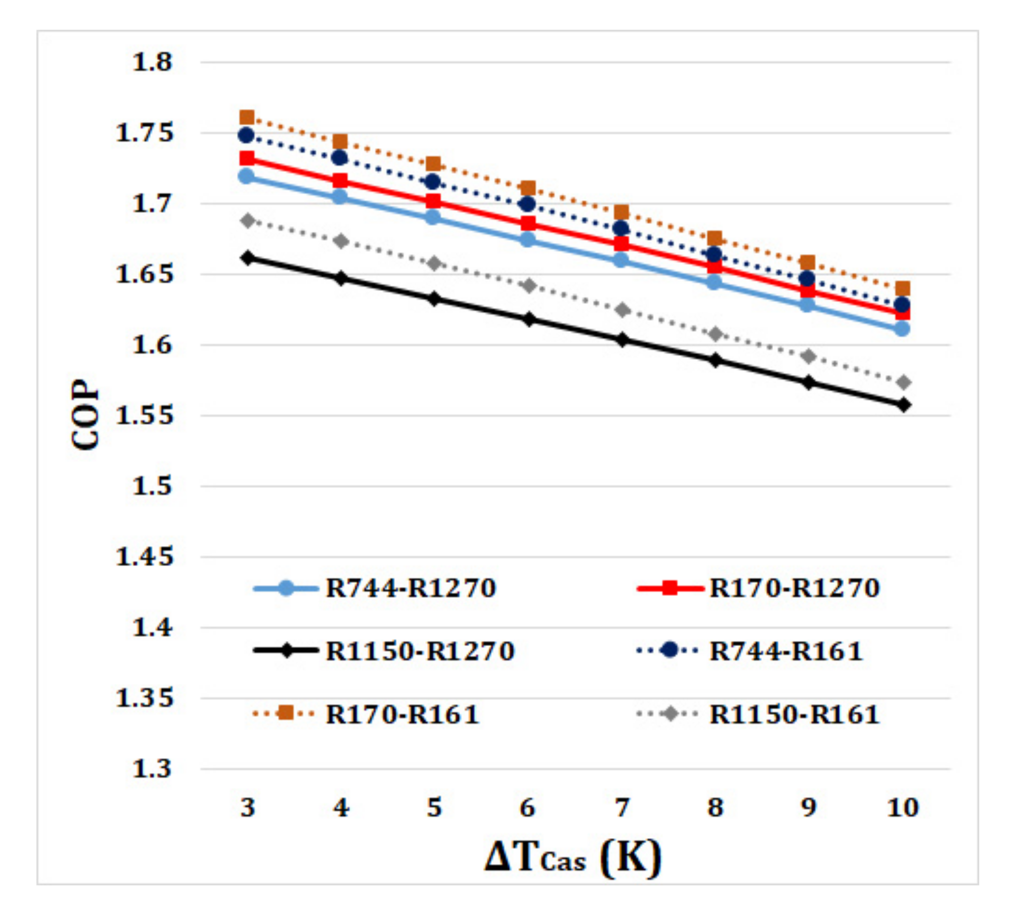
Figure 2 shows the effect of
on the COP of the refrigeration system for different refrigerant pairs. The results demonstrate that with an increase in
from 3 to 10 K, the COP decreases significantly for all refrigerant pairs. It is observed that all refrigerant pairs have almost the same trend of reduction with an increase in
. The reason for a reduction in the COP is that with an increase
, the temperature gap between state points 3 and 5 increases, which causes a reduction in the temperature of state point 5 because the temperature of state point 3 (
) is constant. This leads to increasing the
and as a result, decreasing the COP for all. Among all selected refrigerant pairs, the highest values of COP are obtained for the R170-R161 pair, while the lowest values are obtained when the R1150-R1234yf pair is used as a refrigerant pair. Compared to R744-R717 as a typical refrigerant pair for cascade vapor compression refrigeration systems which its COP ranges between 1.598 and 1.740, R170-R161 shows slightly higher COP ranging between 1.639 and 1.760.
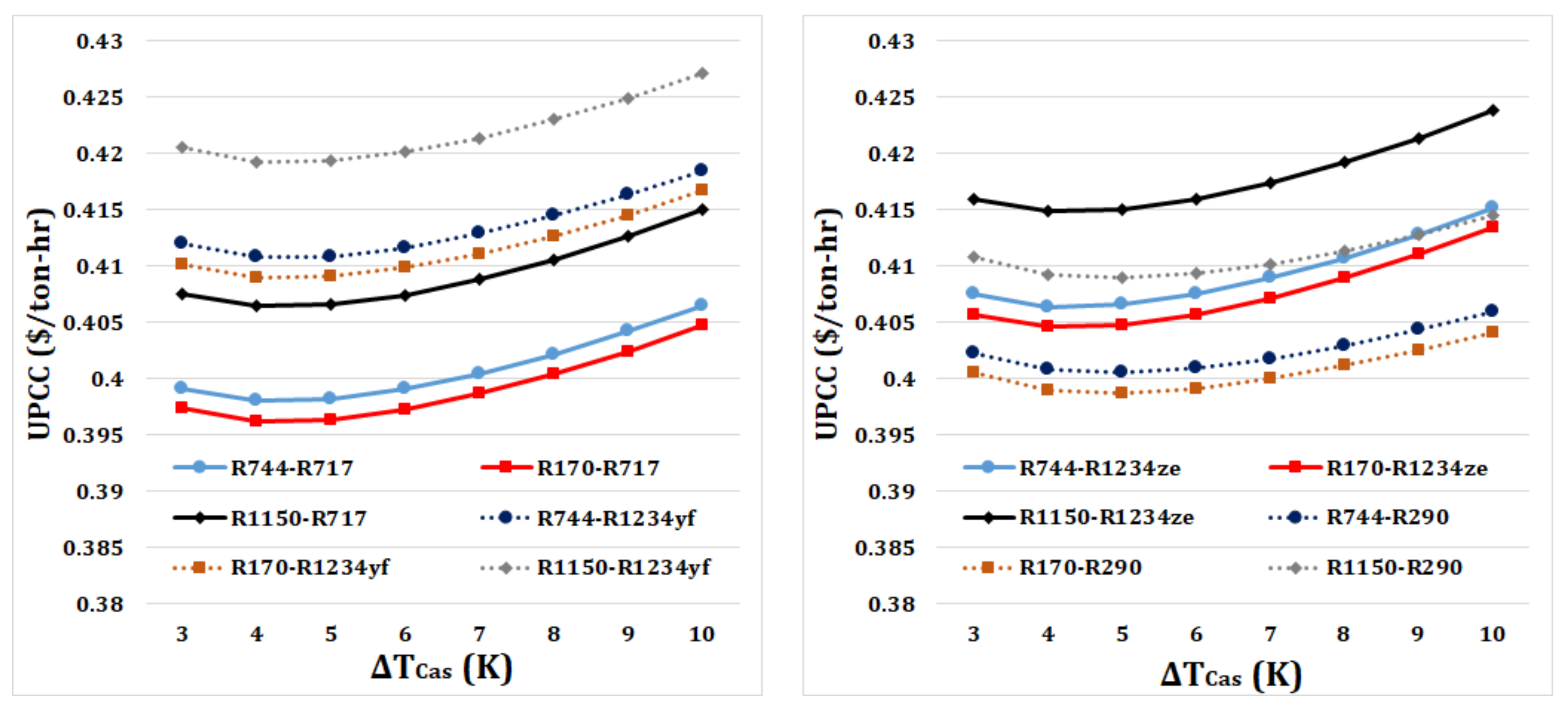
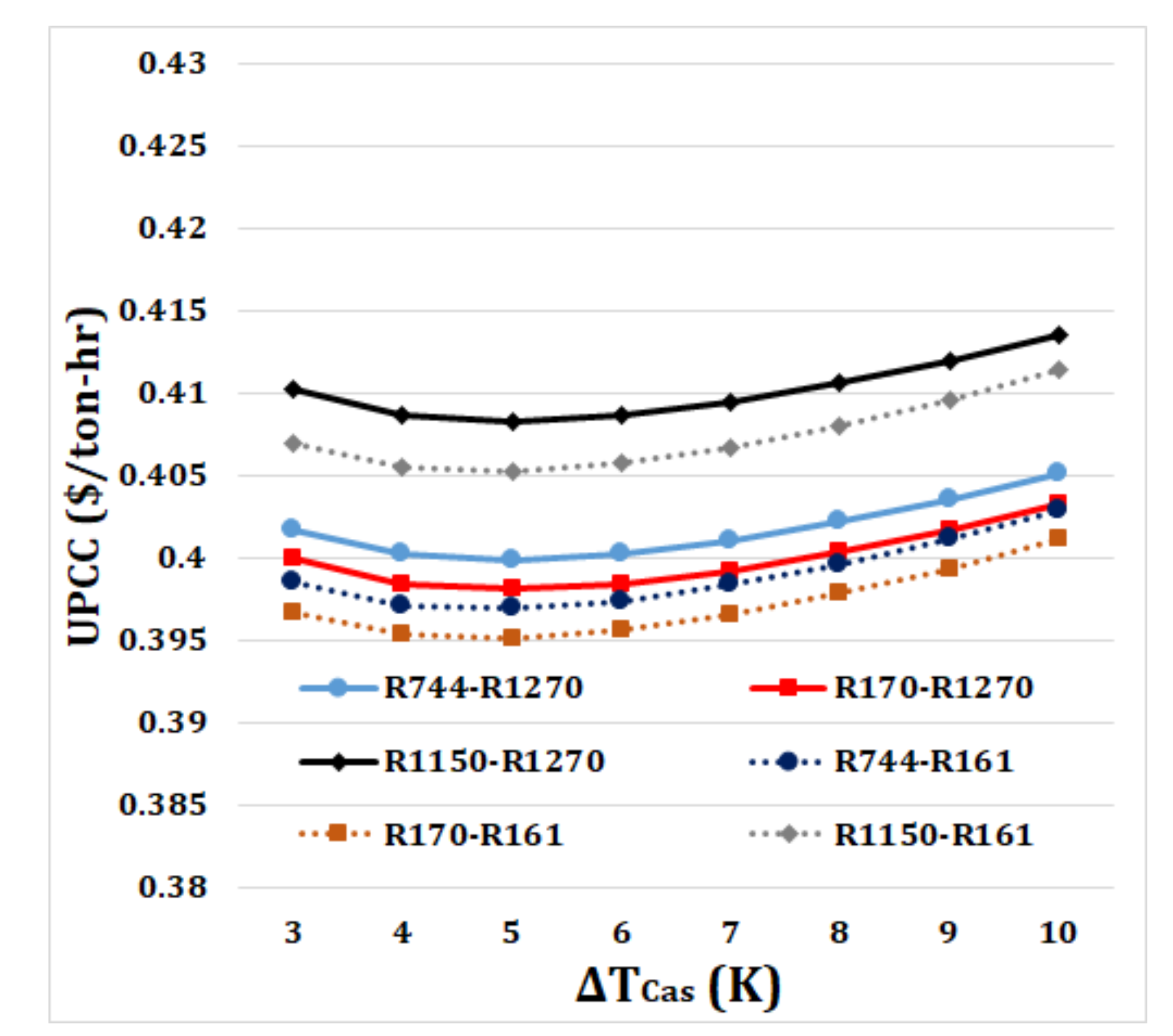
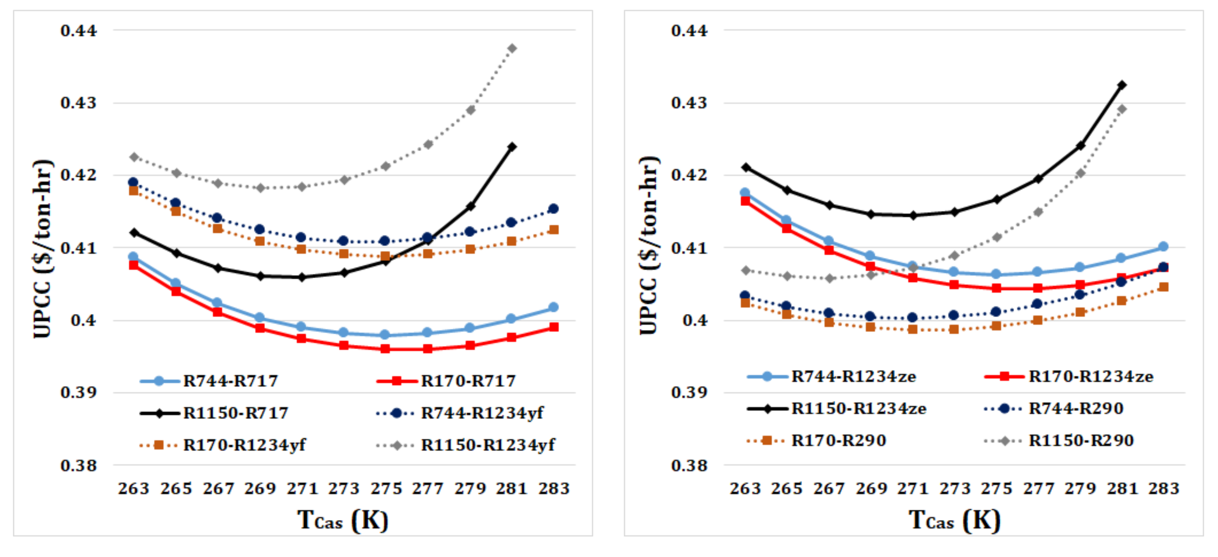
The influence of
on the UPCC of the refrigeration system for different refrigerant pairs is shown in
Figure 3. It is noted that for all refrigerant pairs, the UPCC slightly decreases first and then increases with a further increase in
. As noted, with an increase in
, the COP decreases which causes an increase in the AOC of the system mostly because of an increase in
. On the other hand, with an increase in
, the ACC decreases. The increase in the AOC and the decrease in the ACC along with an increase in
causes that the UPCC decreases first and then increases. The minimum UPCC is obtained when
is close to either 4 K or 5 K. The presented results in
Figure 3 clearly show how changing the refrigerant pairs affects the economic performance of the system demonstrating the importance of the proper selection of a refrigerant pair on the economics of the refrigeration system. The lowest values of UPCC, ranging between
$0.397/ton-hr and
$0.401/ton-hr, are obtained when R170-R161 is used as a refrigerant pair while the highest UPCC values, ranging between
$0.421/ton-hr and
$0.427/ton-hr, are attained for R1150-R1234yf. For R744-R717 as a typical refrigerant pair of cascade refrigeration cycles, the UPCC values are between
$0.399/ton-hr and
$0.407/ton-hr which are slightly higher than those of R170-R161 as the most economical refrigerant pair.
As noted earlier,
is the temperature of the low-temperature refrigerant exiting the cascade heat exchanger (state point 3 in
Figure 1).
is another influential parameter on the thermodynamic and economic performance of a dual-evaporator cascade vapor compression refrigeration system.
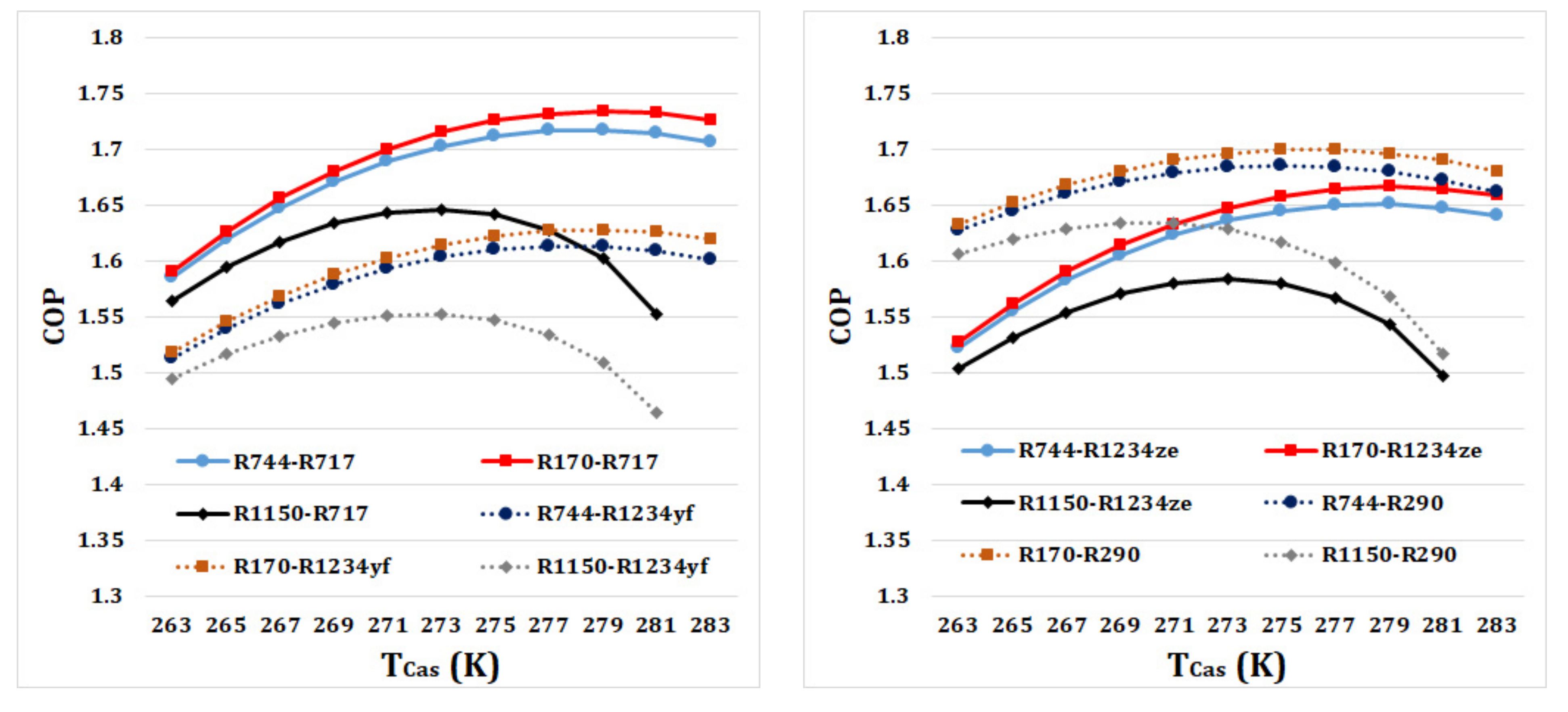
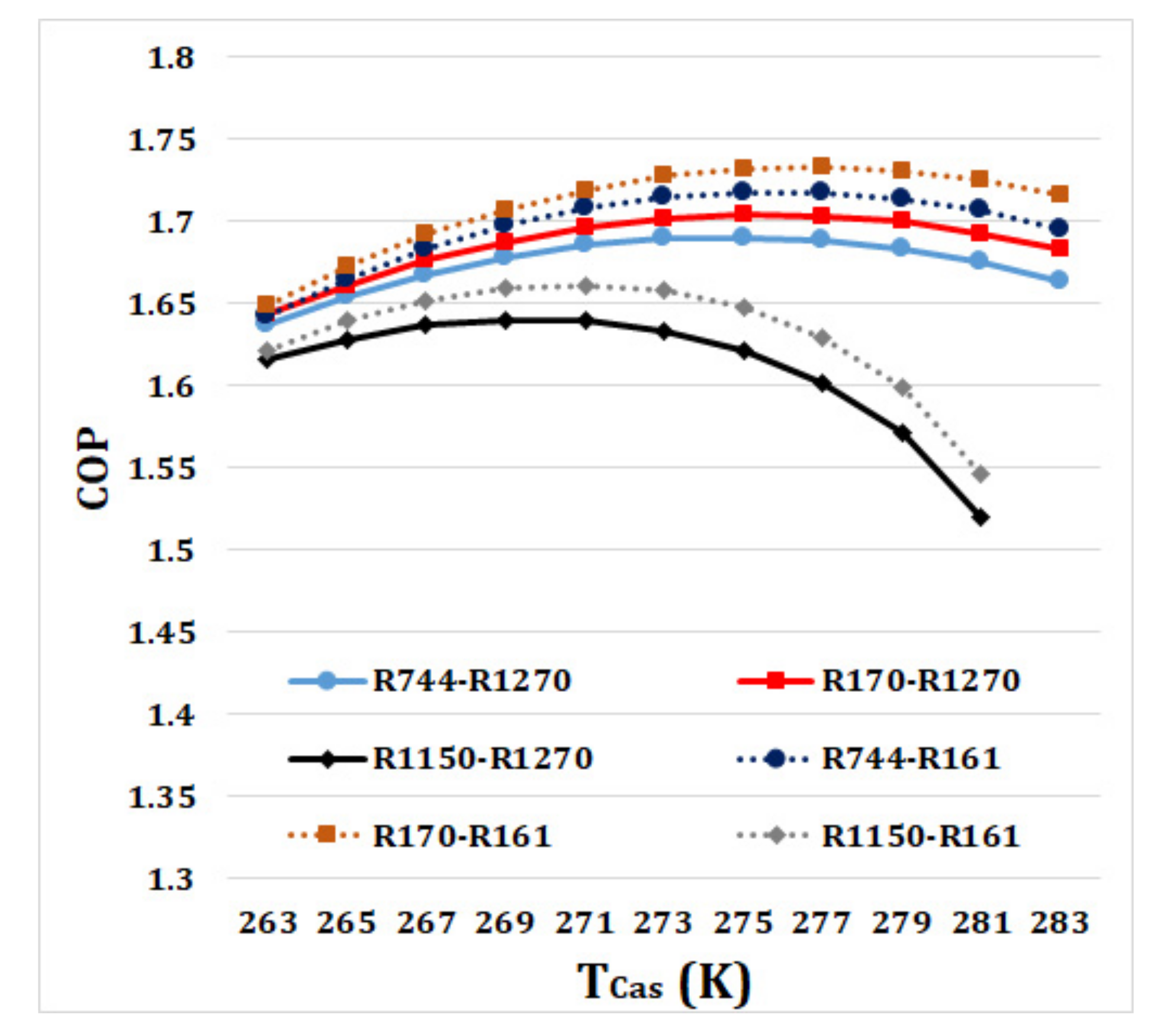
Figure 4 shows the impact of
on the COP for different refrigerant pairs. It is observed that for all refrigerant pairs, with an increase in
from 263 K to 283 K, the COP initially increases and then decreases. These trends of increased and decreased COP with a change in
are different among the examined refrigerant pairs, because of their different thermophysical properties. With an increase in
, the temperature gap between LT-Evap and the cascade heat exchanger (or the condenser of the LT cycle) increases, leading to a rise in
. The increase in
causes an increase in the temperature of state point 5, because of the constant value of
, resulting in a reduction in
. For lower values
values, the decrease in
suppresses the increase in
, leading to an increase in the COP while for higher values
values, the opposite condition happens resulting in a decrease in the COP.
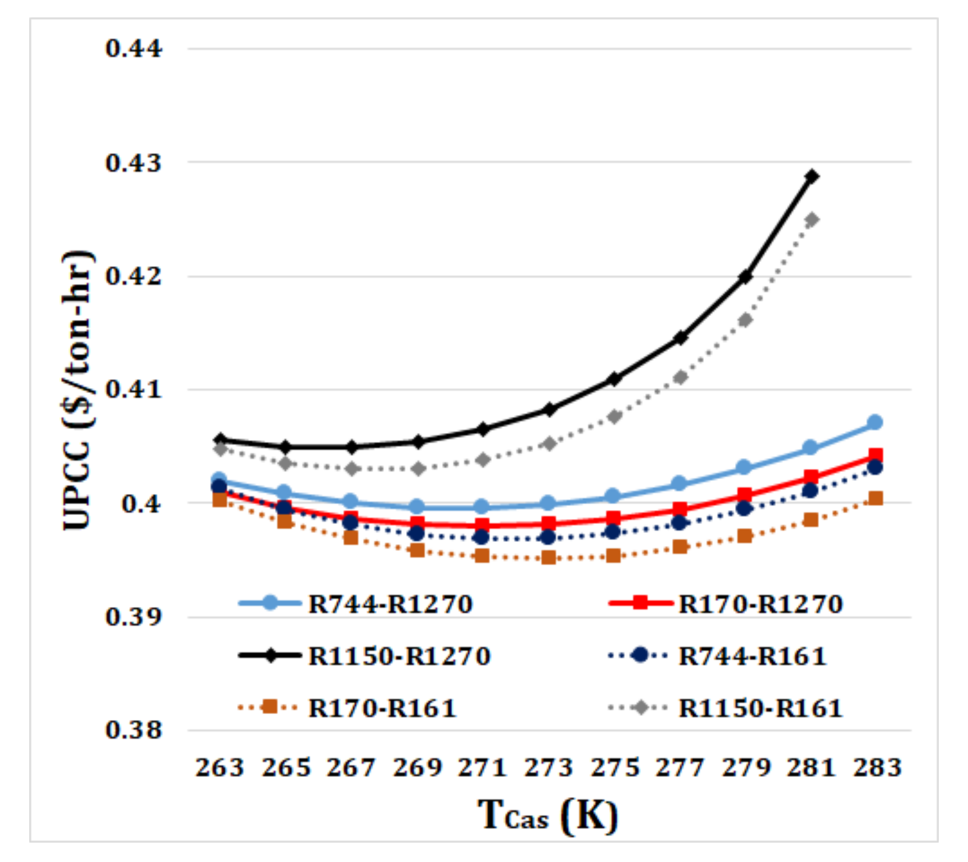
The variation of
with UPCC for different refrigerant pairs is shown in
Figure 5. It is observed that UPCC has a decreasing and increasing pattern with a variation in
. As shown, the trends of these decreases and increases are different for each refrigerant pair, due to their different thermophysical properties. For each refrigerant pair, the minimum UPCC is obtained at a specific value of
, indicating that the same
cannot be used for all refrigerant pairs. For all values of
, the minimum UPCC is obtained when R170-R161 is used as a refrigerant pair. As shown in
Figure 4, when
increases, COP has an increasing and decreasing trend. This results in an opposite trend of variation (a decreasing and increasing trend) in the AOC of the refrigeration cycle. While the ACC of the refrigeration system increases with an increase in
. These different trends of variation in the AOC and ACC cause a decreasing and increasing pattern of variation in the UPCC with an increase in
.
For the previous analyses, the values of
and
were fixed at 233 K and 253 K, respectively. Depending on the application, different values of
and
can be set for a dual-evaporator cascade refrigeration cycle.
Figure 6,
Figure 7,
Figure 8 and
Figure 9 show the influence of a change in either
or
on the COP and UPCC of the cascade refrigeration cycle. For these analyses,
and
are set fixed at 5 K and 273 K, respectively. In addition, when
is varied,
is set at 253 K and when
is varied,
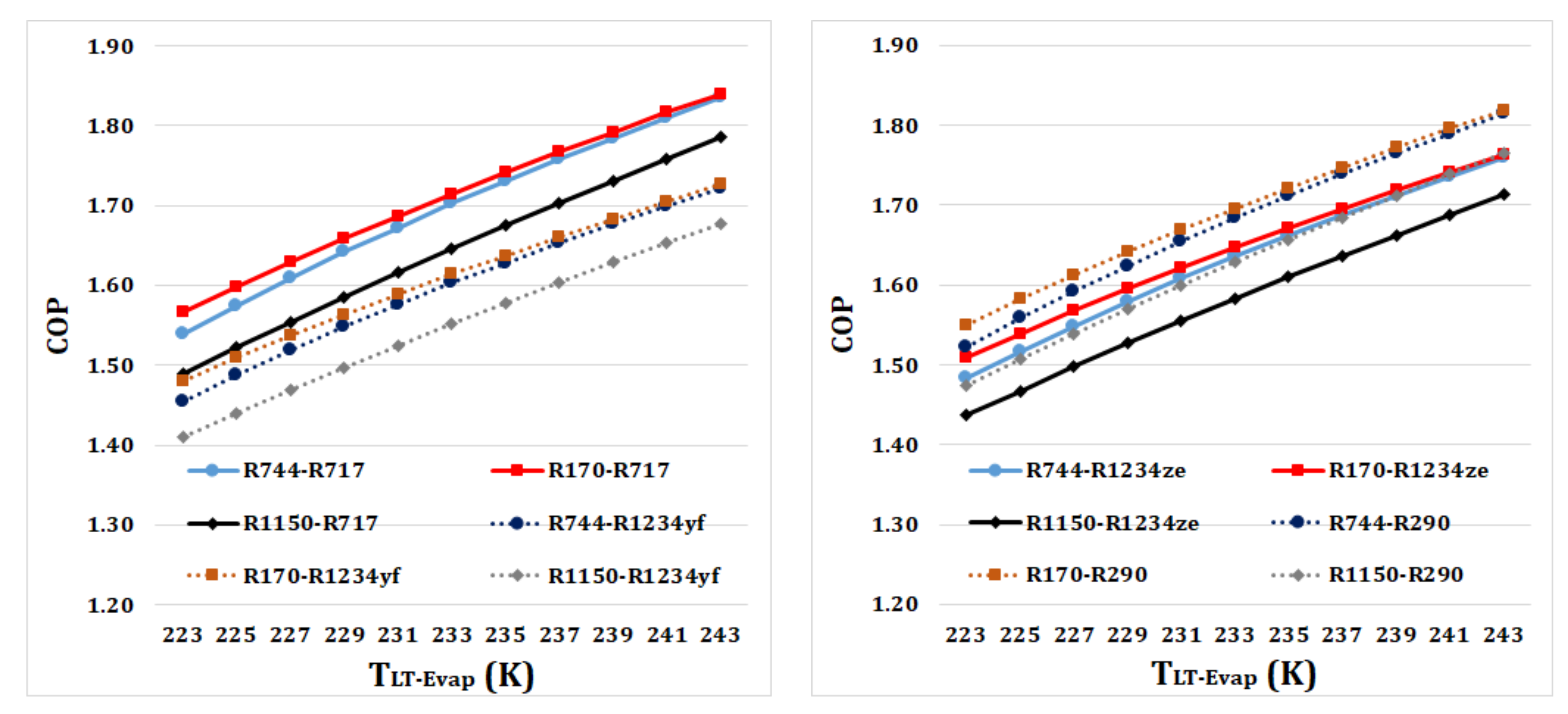
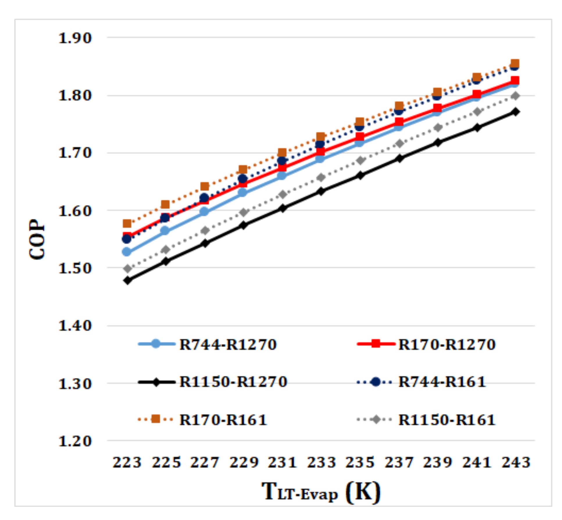
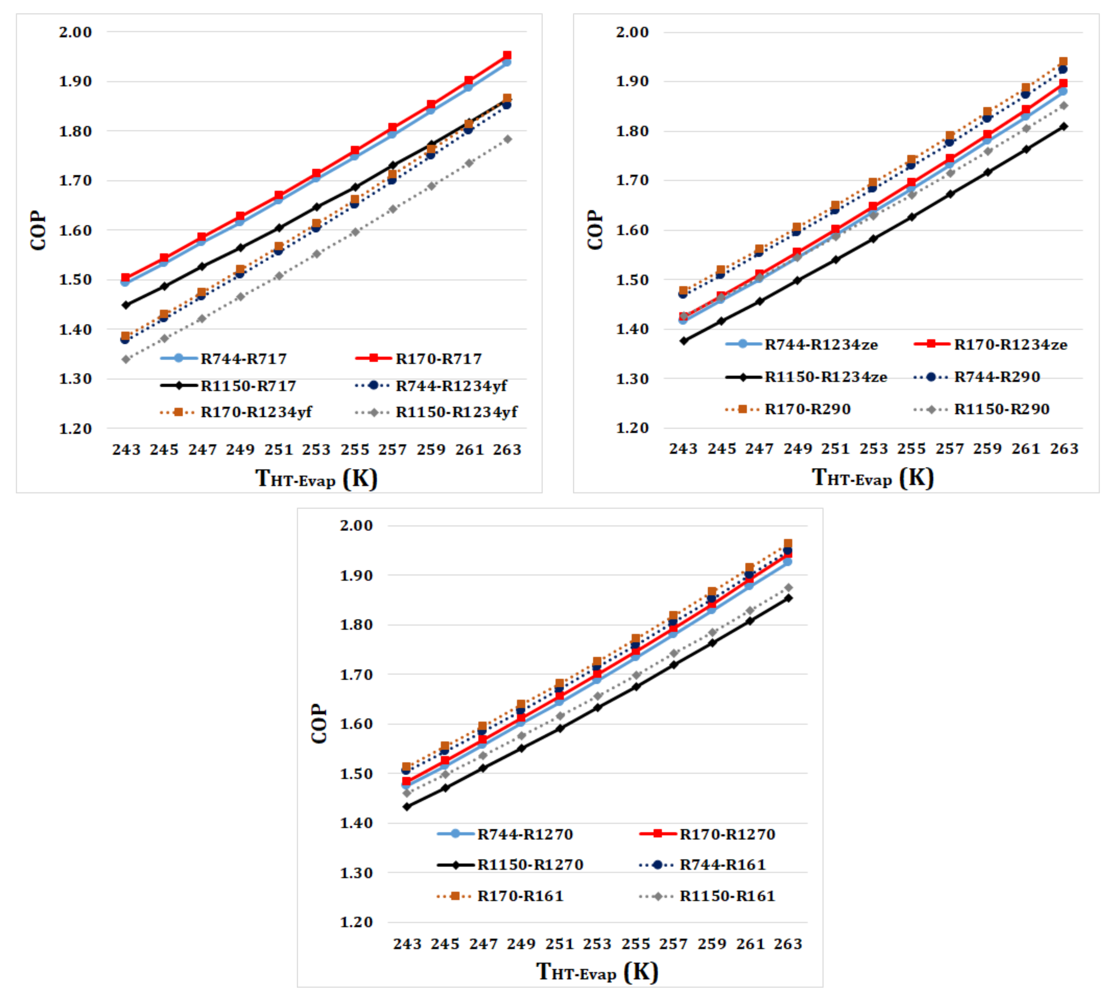
is set at 233 K. According to
Figure 6 and
Figure 8, COP increases with an increase in either
and
. This happens because an increase in the evaporator temperatures decreases the temperature gap between the LT and HT cycles resulting in a decrease in
and
and as a result an increase in the cycle’s COP.
The highest COP values for all
and
values are obtained for the R170-R161 refrigerant pair. While the lowest COP values are obtained when R1150-R1234yf is used as a refrigerant pair. According to
Figure 6 and
Figure 8, using R170-R161 as a refrigerant pair, the COP increases from 1.577 to 1.855 with an increase in
from 223 K to 243 K and increases from 1.514 to 1.965 with an increase in
from 243 K to 263 K, respectively. While for R744-R717 as a typical refrigerant pair, COP increases from 1.539 to 1.835 and from 1.493 to 1.936, respectively. This shows an advantage of R170-R161 over R744-R717 for all examined ranges of
or
.
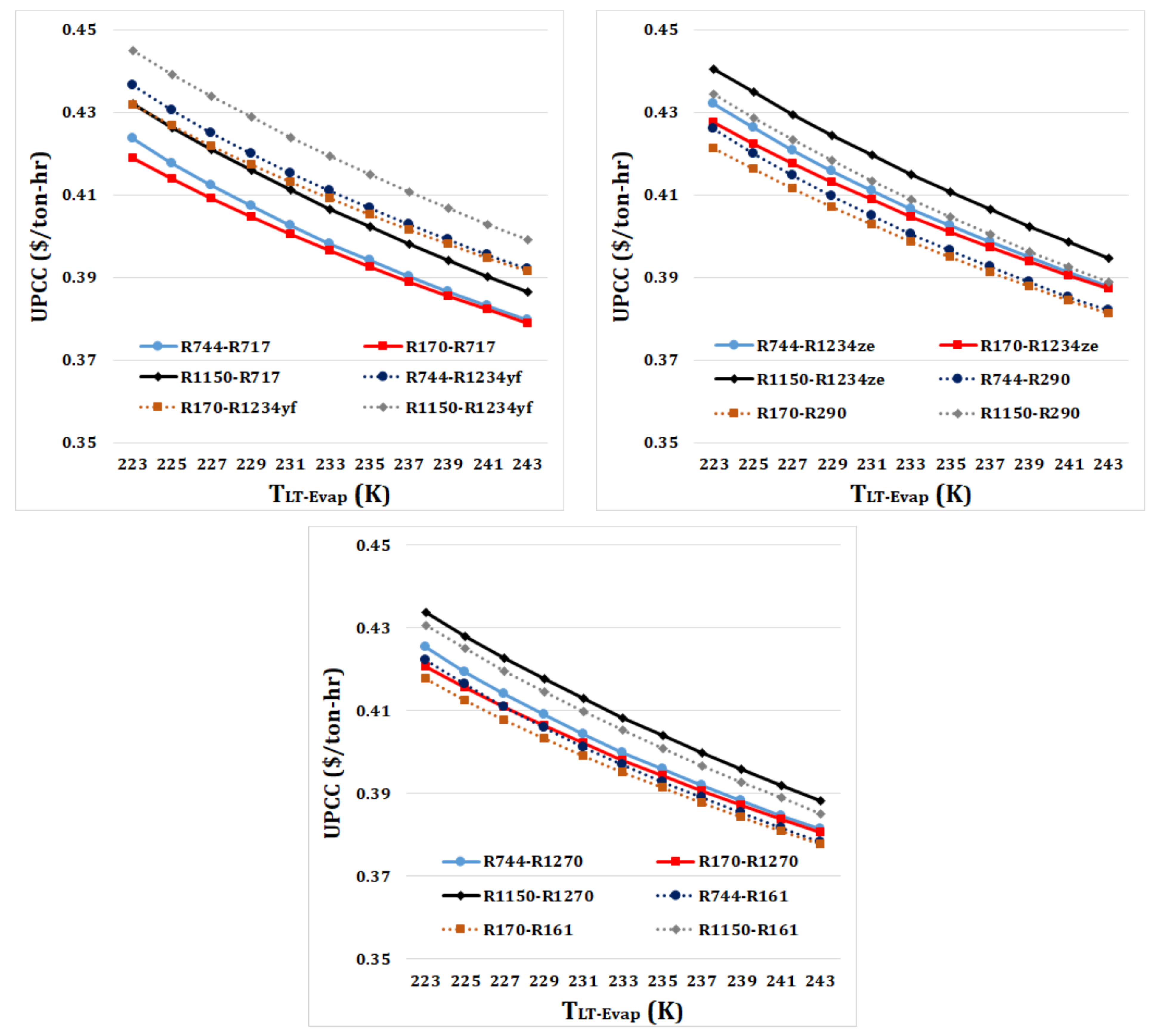
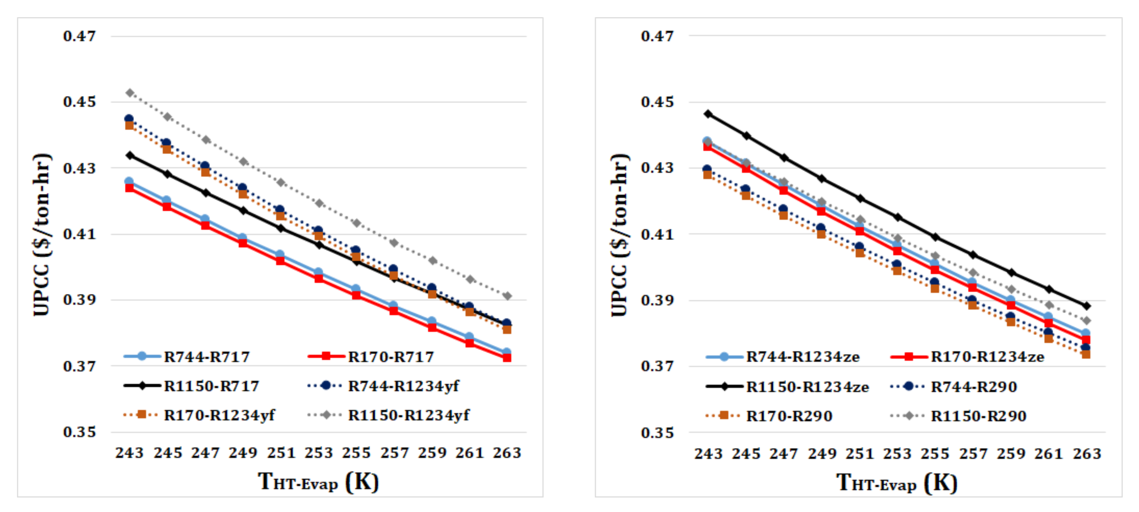
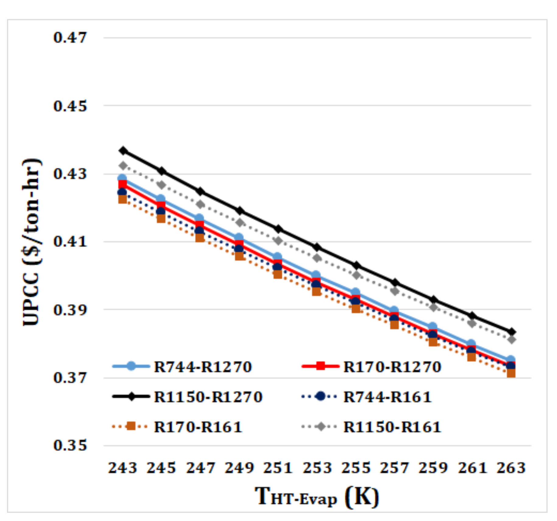
As shown in
Figure 7 and
Figure 9, the UPCC has a decreasing trend with an increase in both
and
. It is observed that the decreasing trend of UPCC is almost the same for all refrigerant pairs. With an increase in
and
, the AOC of the refrigeration cycle decreases mostly because of an increase in the COP. Also, the ACC decreases because of a decrease in the size of components, especially the compressors. The decrease of both AOC and ACC causes a reduction in the UPCC of the cascade refrigeration cycle. According to
Figure 7 and
Figure 9, the lowest values of UPCC are obtained when R170-R161 is used as a refrigerant, followed by R170-R717. R744-R717, as a typical refrigerant pair of cascade refrigeration cycles, is placed as the fourth-best refrigerant pair. With a variation of
from 223 K to 243 K, the UPCC for the refrigerant pairs of R170-R161, and R170-R717 varies from
$0.418/ton-hr to
$0.378/ton-hr, and from
$0.419/ton-hr to
$0.379/ton-hr, respectively. When
from 243 K to 263 K, the UPCC for the refrigerant pairs of R170-R161, and R170-R717 reduces from
$0.422/ton-hr to
$0.371/ton-h, and from
$0.424/ton-hr to
$0.372/ton-hr, respectively.
Optimization Results for R170-R161 Refrigerant Pair
As noted, in this study, a decision was made to optimize the dual-evaporator refrigeration cycle by minimizing the UPCC. The results presented in the previous section demonstrated that, under all parametric study conditions, R170-R161 is the most suitable refrigerant pair from both thermodynamic and economic viewpoints. Thus, the optimization is only conducted for the R170-R161 refrigerant pair. The optimum decision variables of
and
were obtained as 4.652 and 272.46, respectively, for the R170-R161 refrigerant pair. It is noticed that these values are very close to the values (5 K and 273 K) selected as default values for
and
in the above analyses.
Table 7 presents the optimum values of the main thermodynamic and economic results obtained for the cascade cycle that uses R170-R161 as a refrigerant pair. It is found that optimizing the cycle gives slightly higher COP and lower UPCC values compared to the values presented in
Table 7. After the optimization, the values of AOC and ACC slightly decrease.
The rest of the results from here deals with studying the influence of different important parameters on the performance of an optimized cascade refrigeration cycle that uses the R170-R161 pair. For each analysis, two decision variables of
and
are optimized for each specific value of the parameters that are varied. The results of these parametric studies are presented in
Figure 10,
Figure 11,
Figure 12,
Figure 13 and
Figure 14 and discussed in the following.
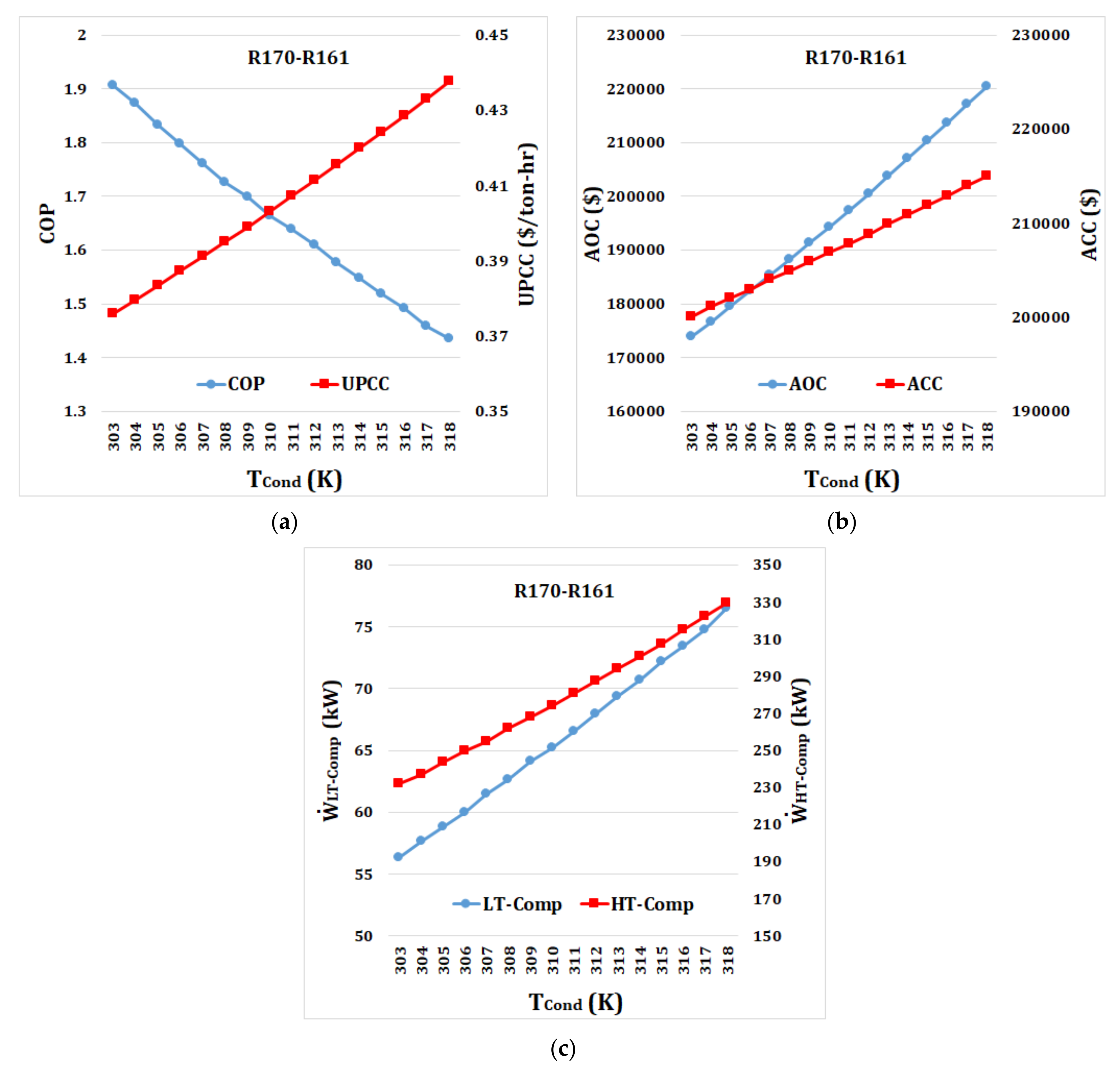
Figure 10 presents the effect of
on several thermodynamic and economic parameters of the optimized cycle using R170-R161 as a refrigerant pair. With an increase in
from 303 K to 318 K, the optimum values of
and
vary from 4.83 K to 4.34 K and from 269.7 K to 277.5 K, respectively. According to
Figure 10a, an increase in
causes a decrease in COP, and an increase in UPCC. When
increases from 303 K to 318 K, COP decreases significantly from 1.903 to 1.436 and UPCC increases substantially from
$0.376/ton-hr to
$0.438/ton-hr.
Figure 10b shows that both AOC and ACC increase with an increase in
. AOC increases from
$173,980 to
$220,491 and ACC increases from
$200,106 to
$215,055 when
increases from 303 K to 318 K. As shown in
Figure 10c, both
and
increase significantly from 56.4 kW to 76.5 kW and from 232.1 kW to 329.3 kW, respectively. With an increase of
, the power requirement of the compressor, especially the high-temperature compressor increases leading to a decrease in the COP and an increase in the AOC. Also, when
increases, the ACC increases because of the increase in the size of the condenser and both compressors. The increase in both AOC and ACC causes a significant increase in the UPCC of the cascade refrigeration system.
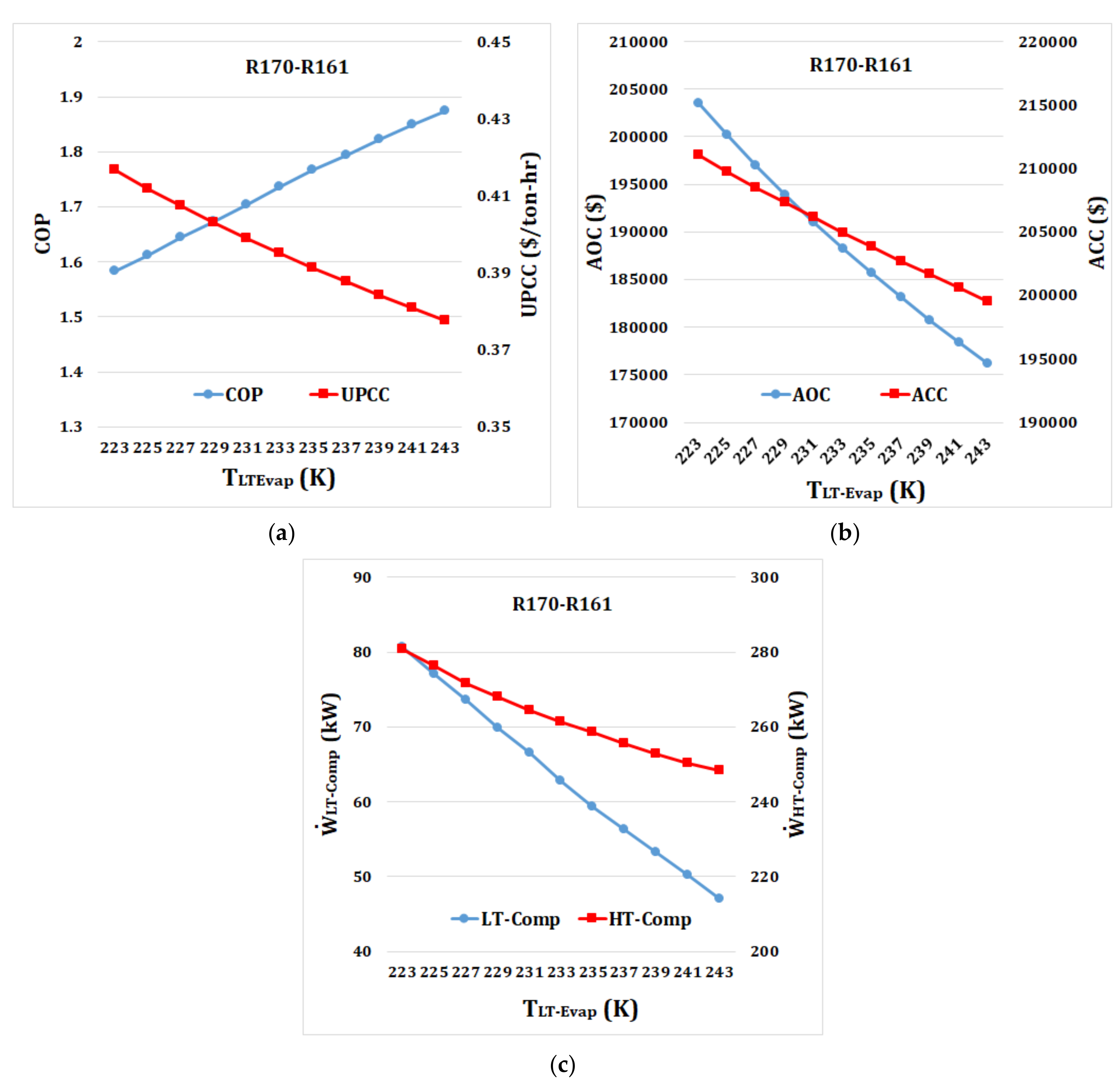
The influence of
on different thermodynamic and economic parameters of the optimized cycle using R170-R161 as a refrigerant pair is shown in
Figure 11. With an increase in
from 223 K to 243 K, the optimum values of
and
change between 4.38 K and 4.91 K and between 268.6 K to 275.41 K, respectively. As shown in
Figure 11a, with an increase in
from 223 K to 243 K, COP increases from 1.584 to 1.875 while UPCC decreases from
$0.417/ton-hr to
$0.377/ton-hr. According to
Figure 11b, both AOC and ACC decrease with an increase in
. When
increases from 223 K to 243 K, AOC and ACC decrease from
$203,496 to
$176,117 and from
$211,072 to
$199,513, respectively.
Figure 11c shows that an increase in
causes a reduction in
and
from 80.7 kW to 47 kW and from 280.7 kW to 248.2 kW, respectively.
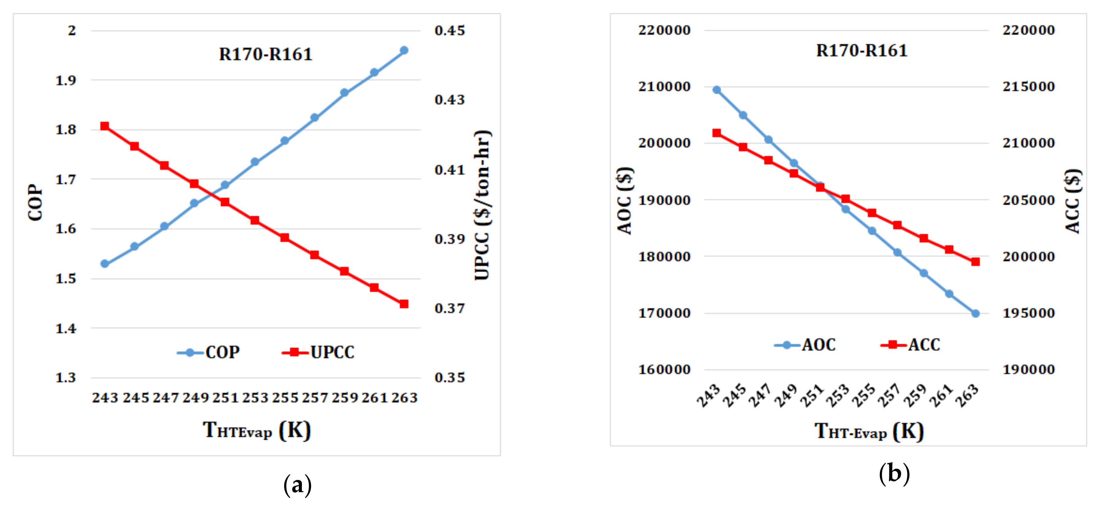
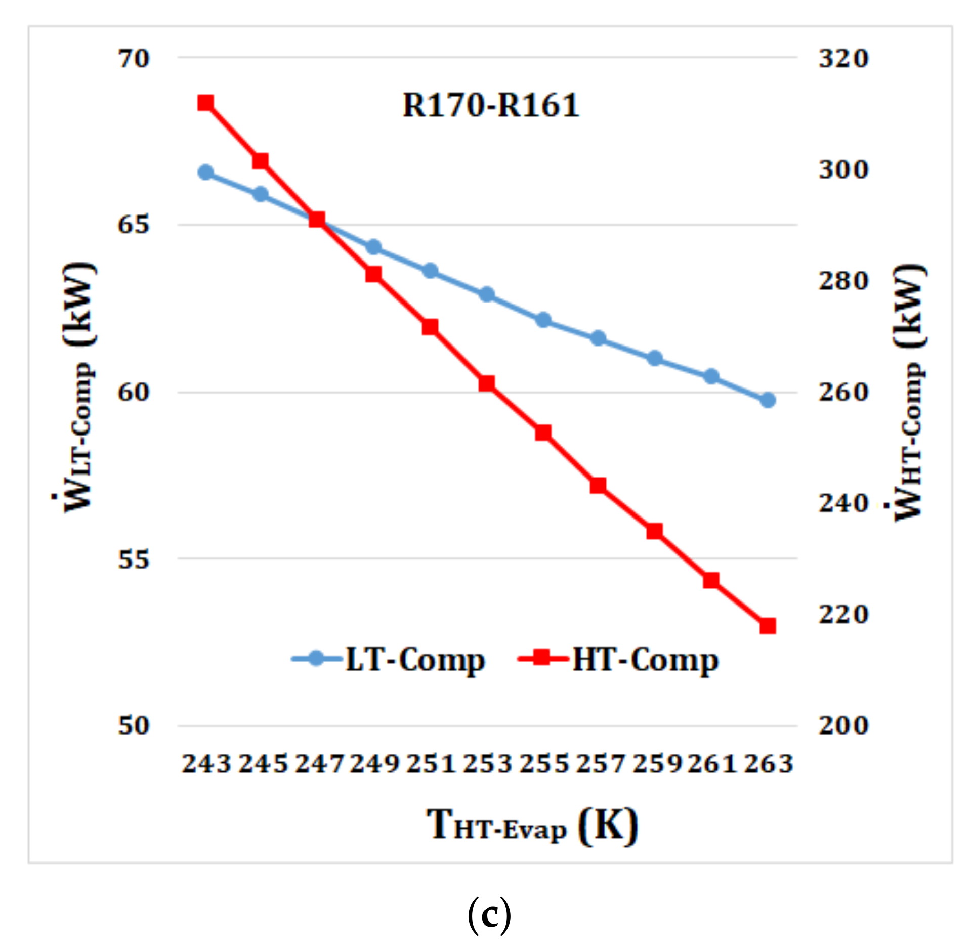
Figure 12 shows the influence of a change in
on different parameters. The presented results show that the trend of increasing and decreasing of the parameters with
is relatively similar to that of
. The optimum values of
and
have a slight change with an increase in
.
increases from 4.61 K to 4.69 K and
decreases from 273.89 K to 271.15 K, respectively. According to
Figure 12a, an increase in
from 243 K to 263 K results in increasing COP from 1.528 to 1.959 and decreasing UPCC from
$0.422/ton-hr to
$0.371/ton-hr.
Figure 12b shows that AOC and ACC decrease from
$209,302 to
$169,809 and from
$210,866 to
$199,442, respectively. As shown in
Figure 13c, with an increase in
from 243 K to 263 K both
and
reduce from 66.5 kW to 59.7 kW and from 311.7 kW to 217.5 kW, respectively.
In all previous analyses of this study,
and
were set fixed at 200 kW and 500 kW, respectively. It is, however, interesting to examine the influence of
and
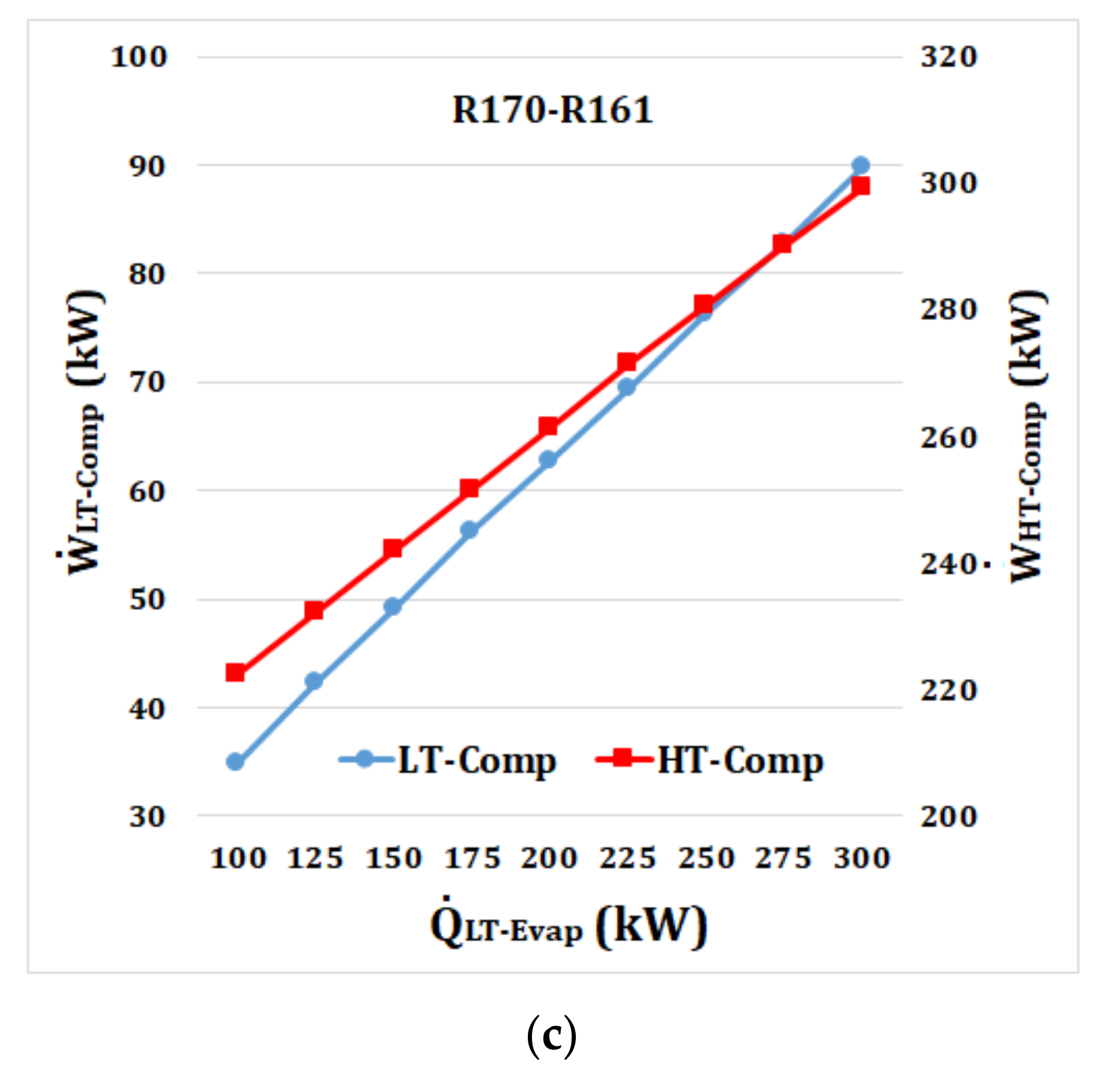
on different thermodynamic and economic parameters of the cascade refrigeration cycle. With an increase in
, the optimum values of
and
vary from 4.48 K to 4.63 K and from 275.1 K to 271.2 K, respectively.
Figure 13a shows the influence of a change in
on COP and UPCC. The results show that with an increase in
, COP and UPCC decrease, but with a different trend. When
increases from 100 kW to 300 kW, COP and UPCC decrease from 1.845 to 1.656 and from
$0.398/ton-hr to
$0.388/ton-hr, respectively. As shown in
Figure 13b, both AOC and ACC increase from
$156,737 to
$217,859 and from
$182,650 to
$223,824, respectively. According to
Figure 13c,
and
both increase with an increase
due to an increase in the size of the refrigeration system.
increases from 34.9 kW to 89.7 kW and
increases from 222.5 kW to 299.4 kW.
With an increase in , the size of the LT and HT cycles and the amounts of and increase. As the increase in and outweighs the increase in , the COP decreases with an increase in . The AOC value increases because of an increase in and and the power requirement of the condenser and LT-Evap. Also, the ACC increases because of an increase in the size of the LT and HT cycles. The increase in the AOC and ACC values is less than the increase in , resulting in a decrease in the UPCC of the cycle.
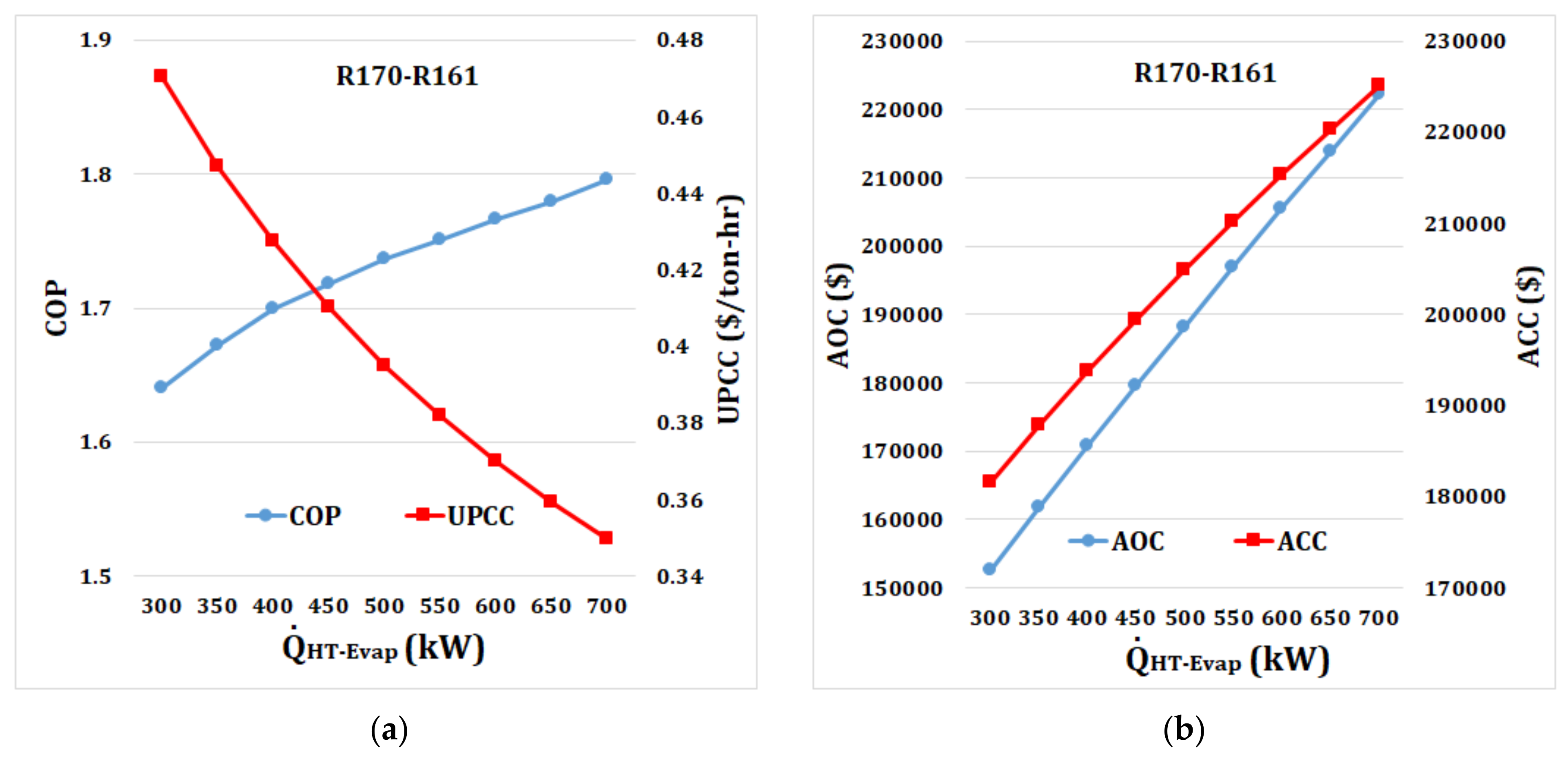
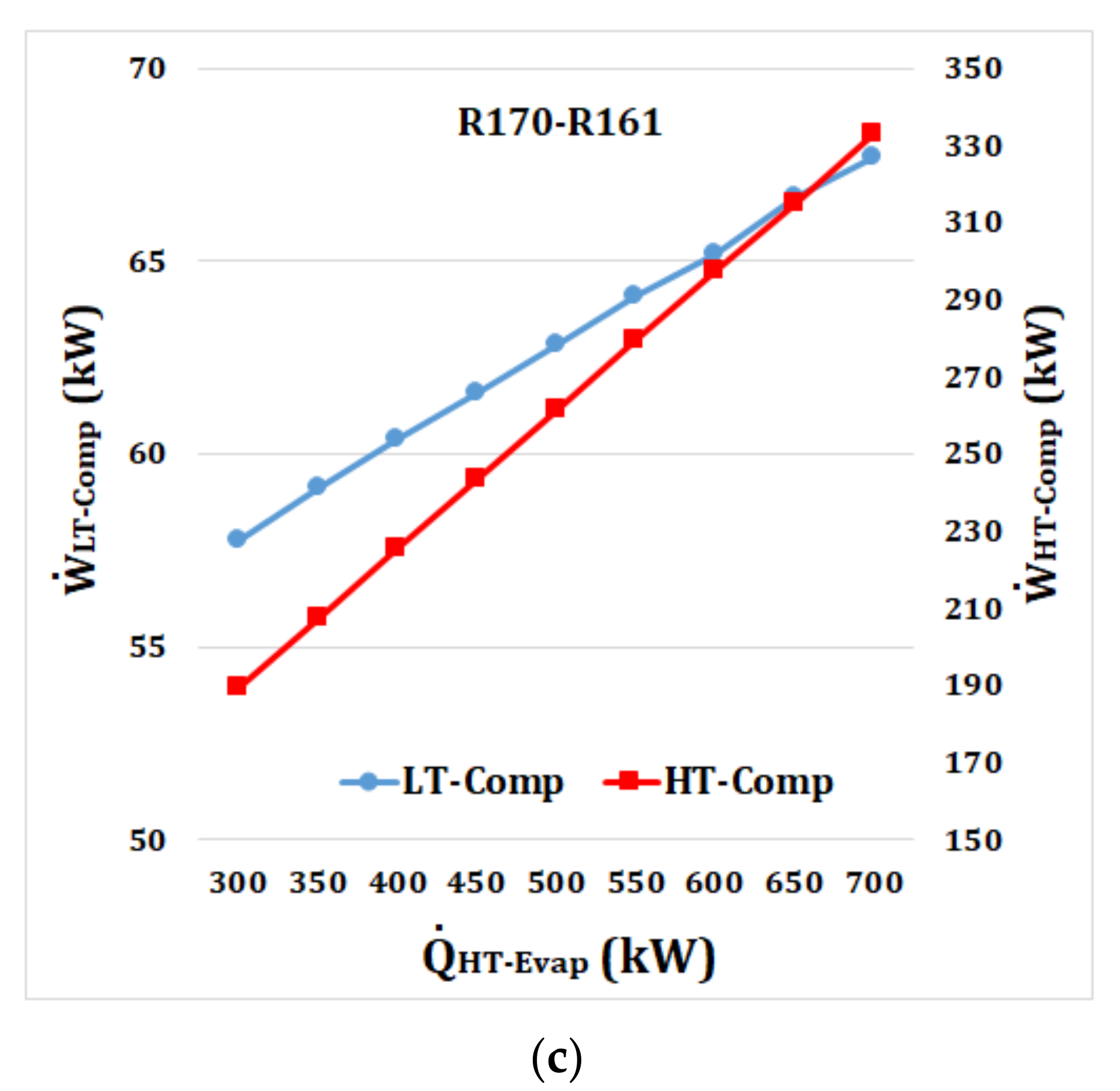
Figure 14 shows the impact of
on different thermodynamic and economic parameters of the cascade refrigeration cycle. With a variation of
from 300 kW to 700 kW, the optimum values of
and
vary from 4.69 K and 4.64 K and from 270.3 K to 274.3 K, respectively. Based on the results of
Figure 14a, with an increase in
from 300 kW to 700 kW, COP increases from 1.640 to 1.796 while UPCC decreases from
$0.470/ton-hr to
$0.350/ton-hr. According to
Figure 14b,c, with an increase in
, AOC, ACC,
, and
have a similar trend as those of
Figure 13b,c.
Figure 14b shows both AOC and ACC experience a significant increase from
$152,699 to
$222,312 and from
$181,603 to
$225,132, respectively when
increases from 300 kW to 700 kW. As shown in
Figure 14c,
and
have an increasing trend from 57.8 kW to 67.7 kW and from 189.2 kW to 332.8 kW, respectively.
An increase in causes an increase in the size of the HT cycle and the amount of . With an increase in , the optimum value of increases, which leads to increasing the temperature gap between LT-Evap and the cascade heat exchanger (or the condenser of the LT cycle) and consequently increasing the . The increase in outweighs the increase in and , resulting in an increase in the COP of the cascade cycle. With an increase in , the AOC increases because of an increase in and and the power requirement of the condenser and HT-Evap. Also, the ACC increases because of an increase in the cycle’s size. The UPCC of the cycle decreases because the increase in the AOC and ACC is lower than the increase in .
5. Conclusions
In this work, a comprehensive thermodynamic and economic analysis was carried out to investigate the potential of using 18 environmentally friendly refrigerant pairs in a dual-evaporator cascade refrigeration system and identify the most suitable refrigerant couple. The main concluding remarks are presented below.
According to the thermodynamic and economic findings, for all examined design and operating conditions, the R170-R161 pair and R1150-R1234yf pair were identified as the best and worst pairs, respectively. For the base case analysis, the COP of the R170-R161 and R1150-R1234yf pair was obtained as 1.727 and 1.552, respectively, and their UPCC was $0.395/ton-hr and $0.419/ton-hr, respectively. The difference between the thermodynamic and economic performance of the examined refrigerant pairs was because of their different thermophysical properties. The study results demonstrated that using the R170-R161 pair showed an improvement over R717-R744, normally used as a refrigerant pair of cascade refrigeration cycles.
The parametric study results showed that with an increase in , the COP of all refrigerant pairs decreases significantly with almost the same trend. An increase in caused that the UPCC decreased first and then increased. For all refrigerant pairs, an increase in caused that the COP increased initially and then decreased while UPCC had a decreasing and increasing pattern with a variation in . These decreases and increases patterns were found to be different for each refrigerant pair, due to their different thermophysical properties. For each refrigerant pair, the minimum UPCC was obtained at a specific value of , indicating that the same cannot be used for all refrigerant pairs. An increase in and caused an increase in the COP and a decrease in the UPCC of all refrigerant pairs.
Optimization using a PSO algorithm was made to optimize the cycle by minimizing the UPCC for R170-R161 as the most suitable refrigerant pair. The influence of different parameters including , , , , and was further investigated on the performance of an optimized cycle that used R170-R161 refrigerant pair. It was found that variation of and had the most influence on the performance of the optimized cycle.
In summary, this study provided useful insight regarding the best refrigerant pair and the importance of the proper selection of refrigerant pairs on the economic and environmental performance of a dual-evaporator cascade refrigeration cycle to maximize the efficiency and minimize the cost and negative environmental impacts.
Future studies should focus on more detailed analysis and equipment sizing and selection of the dual-evaporator cascade refrigeration cycle that used the R170-R161 pair. Furthermore, in future studies, dynamic analysis of the system under variable loads should be conducted and proper control strategies should be developed to ensure the proper operation of the system under variable loads.


