
Separation Characteristics of an Axial Hydrocyclone Separator


1
College of Pipeline and Civil Engineering, China University of Petroleum (East China), Qingdao 266580, China
2
East China Petroleum Bureau of China Petrochemical Corporation, Nanjing 210019, China
*
Author to whom correspondence should be addressed.
Processes 2021, 9(12), 2288; https://0-doi-org.brum.beds.ac.uk/10.3390/pr9122288
Submission received: 1 November 2021
/
Revised: 13 December 2021
/
Accepted: 15 December 2021
/
Published: 20 December 2021
(This article belongs to the Topic Modern Technologies and Manufacturing Systems)
Abstract
:An innovative axial hydrocyclone separator was designed in which a guide vane was installed to replace a conventional tangential inlet, potentially aggravating inlet turbulence. The characteristics of velocity distribution, concentration distribution, and pressure distribution inside the separator were obtained through the numerical simulation of the turbulent flow of oil and water. The results showed that the flow field presented good symmetry, which eliminated the eccentric turbulence phenomenon in the conventional hydrocyclone separators and was beneficial for the oil–water separation.
1. Introduction
As oil fields continue to be exploited, most have entered the medium and high water content stage, with the water content in the fluids that are extracted form oil wells being as high as 80%, with some fluids even reaching water contents of 90% or more. As the water content in recovered fluids increases, the load on the existing treatment equipment in oilfields also increases, and the economic efficiency of the oilfield decreases. Therefore, it is necessary to develop a high-water content crude oil pre-separation device that has the advantages of a simple structure, high separation efficiency, and low pressure.
Hydrocyclone separators are widely used in oilfield water treatment and in other fields as a piece of highly efficient and energy-saving equipment [1,2,3,4]. A conventional hydrocyclone separator usually uses a tangential inlet structure that restricts the space layout of the separator and that exacerbates turbulence in the inlet. Early researchers focused on experimental studies of tangent cyclone separators. In 1967, the Torrey Canyon oil spill in the North Sea oil field in the UK prompted Martin Thew and Colman to study the use of static cyclone separators for oil and water separation [5]. The changes in liquid–liquid cyclone separator performance under different flow fluctuations were then studied by Trygve Husveg [6]. Young [7] et al. proposed a new cyclone separator geometry model that was based on the 35 mm hydrocyclone that was designed by Colman and Thew. The effects of the operating parameters and the geometric parameters (e.g., inlet size, cylindrical segment diameter, cone angle, cylindrical segment length, inlet flow rate, and oil droplet particle size) on the separation efficiency were studied experimentally. This type of tangent cyclone separator is prone to flow field instability and has a large radial distance [8,9]. The axial flow air cyclone separator that was designed by Swanborn [10] avoids these disadvantages very well. On this basis, Maarten Dirkzwager [11] introduced anaxial fluid–liquid cyclone with a blade in 1996 and studied the internal flow field distribution of the cyclone using a laser Doppler speedometer to discuss the effect of the velocity distribution on the cyclone field. Following Maarten Dirkzwager, Stephen Murphy and RenéDelfo used the Malvern Laser Particle Size Analyzer to measure changes in the sizes of oil droplets in an online cyclone separator [12]. Through numerical simulations of axial flow separators, Min Zhan et al. found that increasing the exit angle, torsion angle, and number of blades in the vortexer can significantly increase the tangential velocity of the fluid in the flow field and can facilitate the aggregation of light fluids [13]. Jaseer E. Hamza et al. experimentally demonstrated that a higher flow rate can be fed into the compact conical axial hydrocyclone compared to conventional hydrocyclones [14]. A new kind of axial hydrocyclone separator was designed in this paper on the basis of previous studies [15,16,17,18,19]. A guide vane was installed in the inlet instead of in the original tangential inlet in order to cause swirl flow.
2. Simulation Methods
A three-dimensional numerical model was established. The distribution rules of the velocity field, concentration field, and pressure field in the separator were obtained using the numerical simulation software Fluent 15.0.
2.1. Geometric Model and Meshing
The structure of the axial hydrocyclone separator is shown in Figure 1. The oil and water mixture enters the inner tube of the separator, and a high-speed swirl field is caused by the guide vane in the inlet. The two phases separate in the radial direction under the centrifugal force due to different densities in the swirl section. Whichever water phase has a greater density gathers at the inner wall of the separator, as the oil phase, which has lower density, gathers at the center of the separator. A slit structure is adopted on the inner tube wall in the water-removal section. The water phase near the inner wall flows out through the four slits, flows into the outer tube, and finally flows out through the bottom-flow outlet. The length of the slit is 100 mm, and the width is 4 mm. The oil phase flows out of the overflow outlet through the overflow tube. The guide vane uses orthogonal arc blades and adopts the following structure parameters: a height of 40 mm, a wrap angle of blade of 150°, an blade outlet angle of 20°, an inside line radius of the blade of 15 mm, an outside line radius of the blade of 25 mm, and three blades. A three-dimensional model of the guide vane is shown in Figure 2.
The flow path inside the separator was meshed with hybrid grids by means of ICEM. Considering the complexity of the guide vane and slit structure, tetrahedral grids were used in the vane and water-removal section. Appropriate refinement was adopted to improve the calculation accuracy. Hexahedral grids were used in other parts of the meshing. The presence of boundary layers was taken into account, so three layers of fine mesh were added near the walls in order to capture the physical fields. In total, there were approximately 850,000 grids. A mesh model of the separator is shown in Figure 3, and a mesh model of the vane is shown in Figure 4.
2.2. Multiphase Model and Turbulence Model
The oil–water turbulent flow can be seen as the flow that occurs between two kinds of immiscible fluid. The mixture model assumes local equilibrium within a small space, with each phase moving at different velocities. It uses a single fluid approach that is similar to the approach that is used in the volume of fluid model (VOF model) but allows each mutual phase to penetrate. It also uses a second-phase volume fraction equation and an algebraic equation to represent the velocity slip between the phases in order to make the solution more accurate and suitable for situations where there is phase mixing or phase separation. As such, a mixture model was chosen wherein the water phase was the continuous phase and the oil phase was the dispersed phase.
The continuity equation for the mixture model is [20]:
where is the average mass velocity, m/s
where and αk are the average velocity and the volume fraction of phase k.
The momentum equation is as follows:
where n is the number of phases; μm is the viscosity of the mixture, Pa∙s; is the kth phase slip velocity, m/s; and R is the Reynolds stress.
The turbulence models that are commonly used for fluent are the standard k-ɛ model, the RNG k-ɛ model, and the Reynolds Stress Model (RSM). The standard k-ɛ model is the simplest turbulence model and is capable of achieving convergence and computational accuracy for general engineering calculations but is not effective in simulating complex flows such as cyclonic flow. The RNG k-ɛ model can be used to simulate complex flows such as jet impingement, separated flows, and cyclonic flows, but it cannot accurately predict strong cyclonic motion due to the limitations of the vortex viscous isotropy assumption. The Reynolds Stress Model (RSM) was chosen for the turbulence model, which considered the effect of turbulence anisotropy and was suitable for complex vortex motion simulation. Therefore, the RSM model was chosen as the turbulence model.
The transport equations of the RSM turbulence model are defined as follows [20]:
where is the Reynold’s stress fraction; Dij, pij, Φij, εij are the turbulent diffusion term, shear stress generation term, stress–strain phase, and viscous dissipation term.
where μt is the turbulent viscosity, Pa∙s; σk = 1, C1 = 1.8, and C2 = 0.6 are the empirical constants
2.3. Calculation Methods
Three kinds of pressure–velocity correlation forms can be chosen when using the solver: SIMPLE, SIMPLEC, and PISO [21,22,23,24,25]. SIMPLE and SIMPLEC are normally used for steady flow calculations, and PISO is usually used for unsteady calculations. The SIMPLE method was chosen in this paper. The discretization schemes that were provided by FLUENT mainly include First Order Upwind, Second Order Upwind, Quick, and Power Law. In general, higher order formats have higher calculations accuracy. To ensure the accuracy of the simulation results on the premise of improving the speed of simulation calculations, the second Order Upwind format was chosen for the simulation calculations [25,26,27,28,29,30,31].
2.4. Boundary Conditions and Physical Property Parameters
2.4.1. Boundary Conditions
The two oil–water two phases were mixed evenly. The velocity inlet was chosen for the inlet boundary. The velocity was 1.5 m/s, and the direction was perpendicular to the entrance. The primary phase was the water phase. The secondary phase was the oil phase, which was evenly distributed in the water phase. The diameter of the oil droplets was 100 μm. The volume fraction of the oil was 30%; The bottom-flow outlet and overflow outlet were set as the outflow boundary condition, which was suitable for the completely developed out flow. The split ratio (F = Qo/Qi, Qo is the overflow outlet flow rate, Qi is the inlet flow rate) was set as 0.4. The liquid–solid interface was processed as the no slip boundary condition.
2.4.2. Physical Properties of the Fluids
Physical property parameters of materials: the density of the water was 998.2 kg/m3, the dynamic viscosity of the water was 0.001003 Pa·s, the density of the oil was 890 kg/m3, and the dynamic viscosity of the oil was 0.05 Pa·s.
2.5. The Test and Verify of Grid Independence
The grid number has an important effect on the convergence and calculation accuracy in CFD simulations. In order to avoid the influence of the grid number, models with the grid numbers 524,506, 764,281, 852,458 and 1,009,426 were calculated in this paper. The calculation results for the separation efficiency and pressure drop are shown in Table 1. It can be seen that when the grid number reaches 852,458, the gap between the calculation results is smaller. Therefore, the grid number that was adopted in the following text is 852,458.
3. Results and Discussion
3.1. Velocity Field
Fluid motion in an axial guide vane hydrocyclone separator is a complex three-dimensional spiral motion. In order to better describe the flow field inside of the separator, the cross section of the end of the guide vane was set as z = 0 mm, and four cross sections (z = 50 mm, z = 150 mm, z = 250 mm, z = 350 mm) were intercepted along the axial fluid direction to simulate and analyze the axial velocity and the tangential velocity under the cylindrical coordinate system (the radial velocity was not discussed in this paper because its value was very small).
3.1.1. Axial Velocity
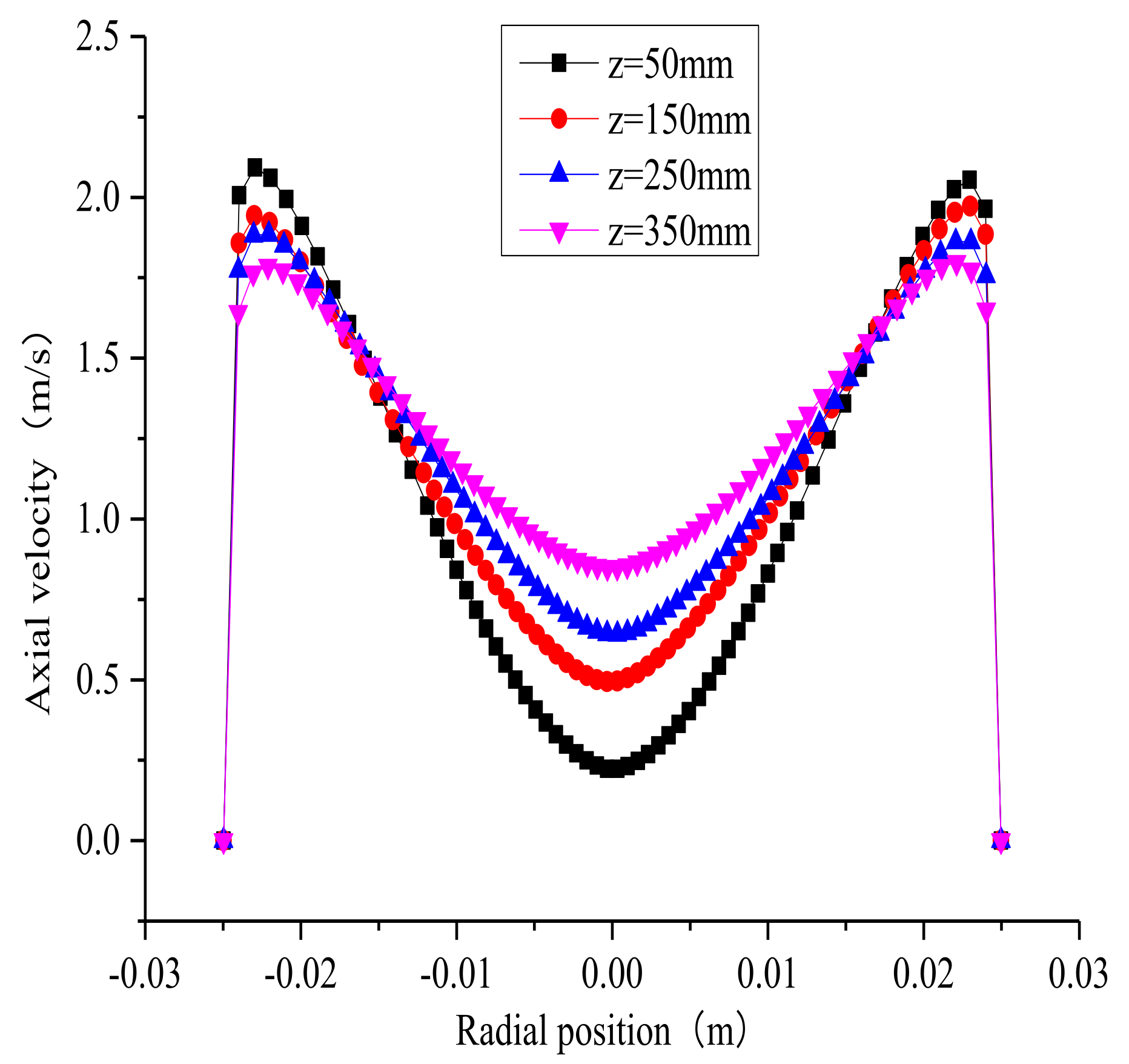
When compared to the tangential velocity, the axial velocity was determined to be smaller and was shown to have a main effect on the residence time in the separator as well as on the discharge velocity after separation. The distribution cloud of the axial velocity inside the separator is shown in Figure 5. It can be seen from the figure that the axial velocity presents an axisymmetric distribution and points to the overflow outlet after the fluid flows out of the guide vane. The axial velocity increases because the diameter of the guide vane decreases after the fluid enters the outflow tube. The axial velocity in the center becomes negative when it nears the end of the guide vane because of the backflow phenomenon that is caused by the low pressure near the end of guide vane during the circumferential motion process of viscous fluid, as shown in Figure 6. Figure 7 and Figure 8 show the distribution cloud of the axial velocity and radial distribution curves in different cross sections. Combining the two figures, it can be seen that there is a thin boundary layer near the wall of the separator. The axial velocity increases from zero to the maximum quickly and then decreases gradually as the radius decreases. The value reaches its lowest point in the center. In the axial direction, the axial velocity of the oil core in the center increases gradually as the distance to the vane increases, which is conducive to promoting the oil core in the center portion that flows forward and as it flows out of the overflow tube.
3.1.2. Tangential Velocity
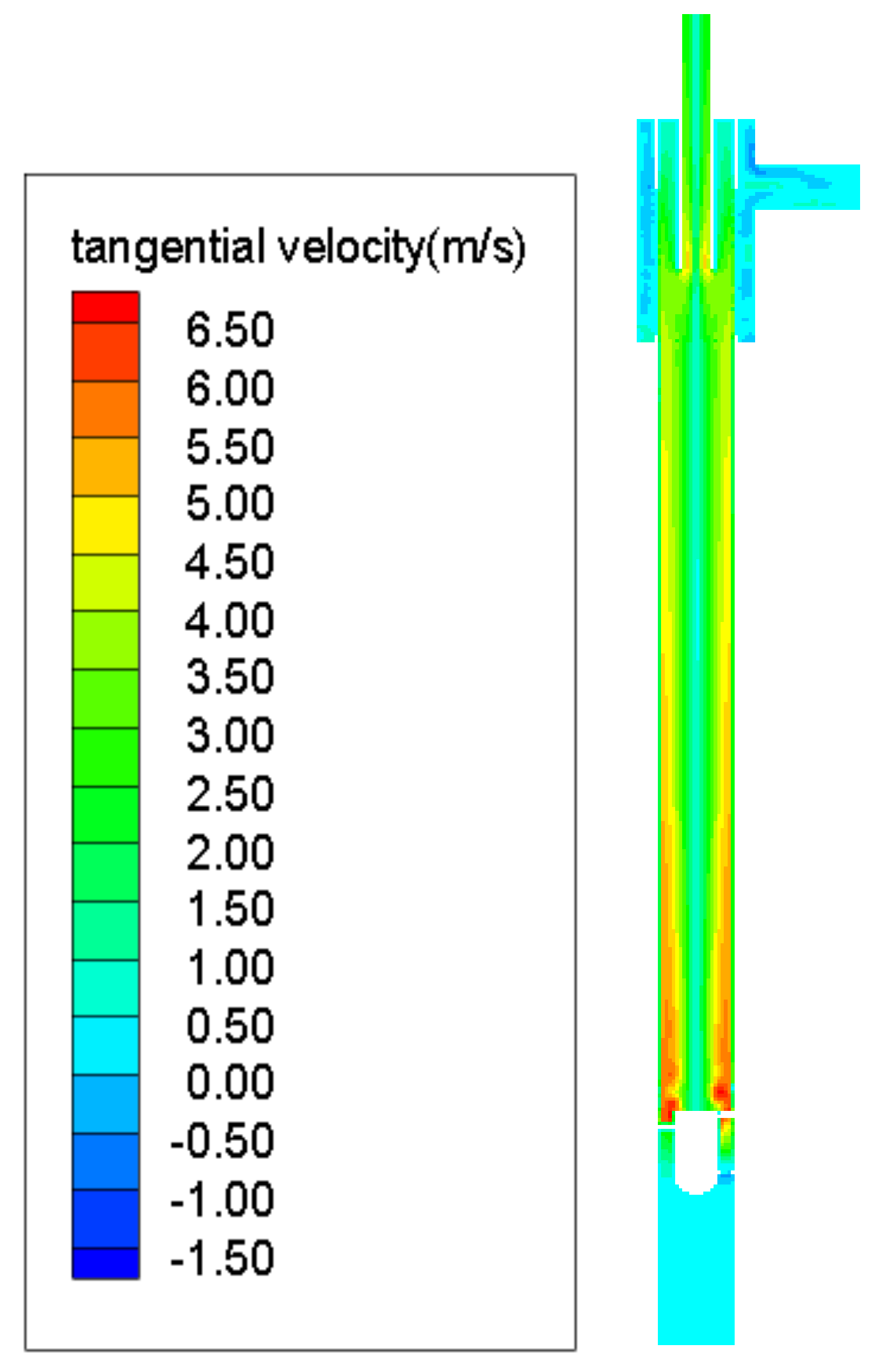
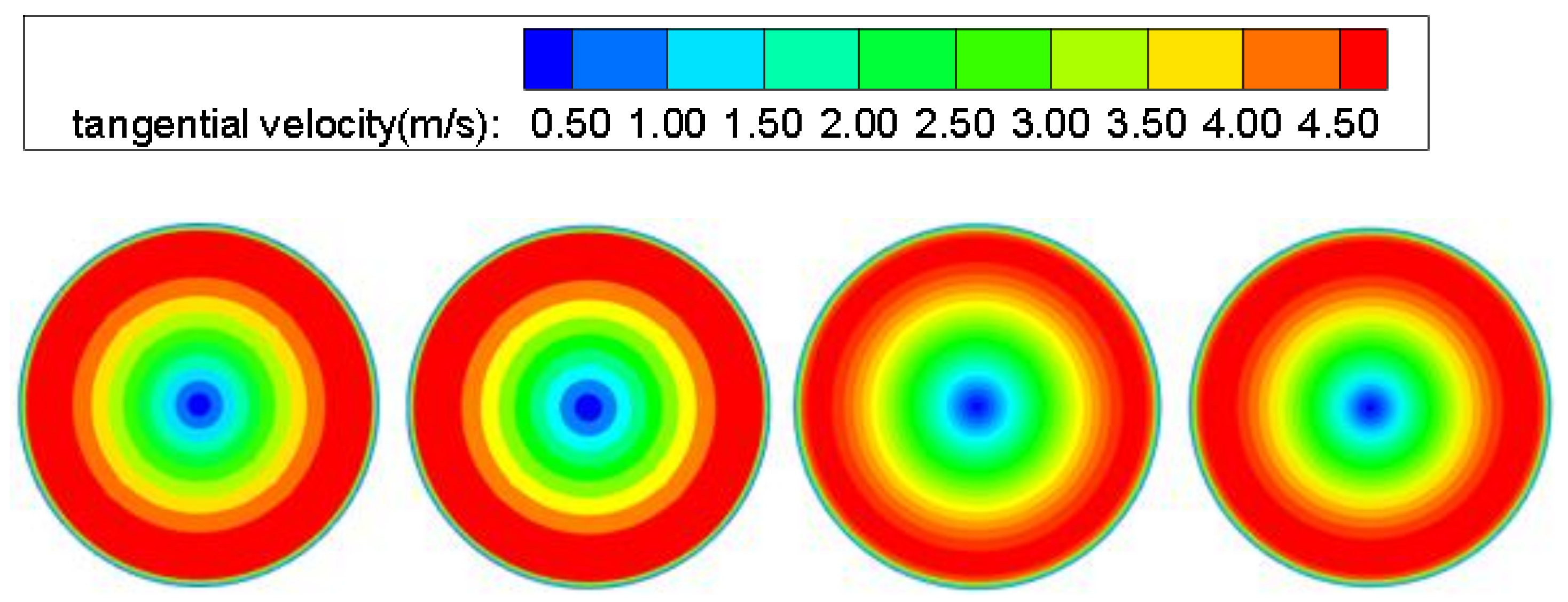
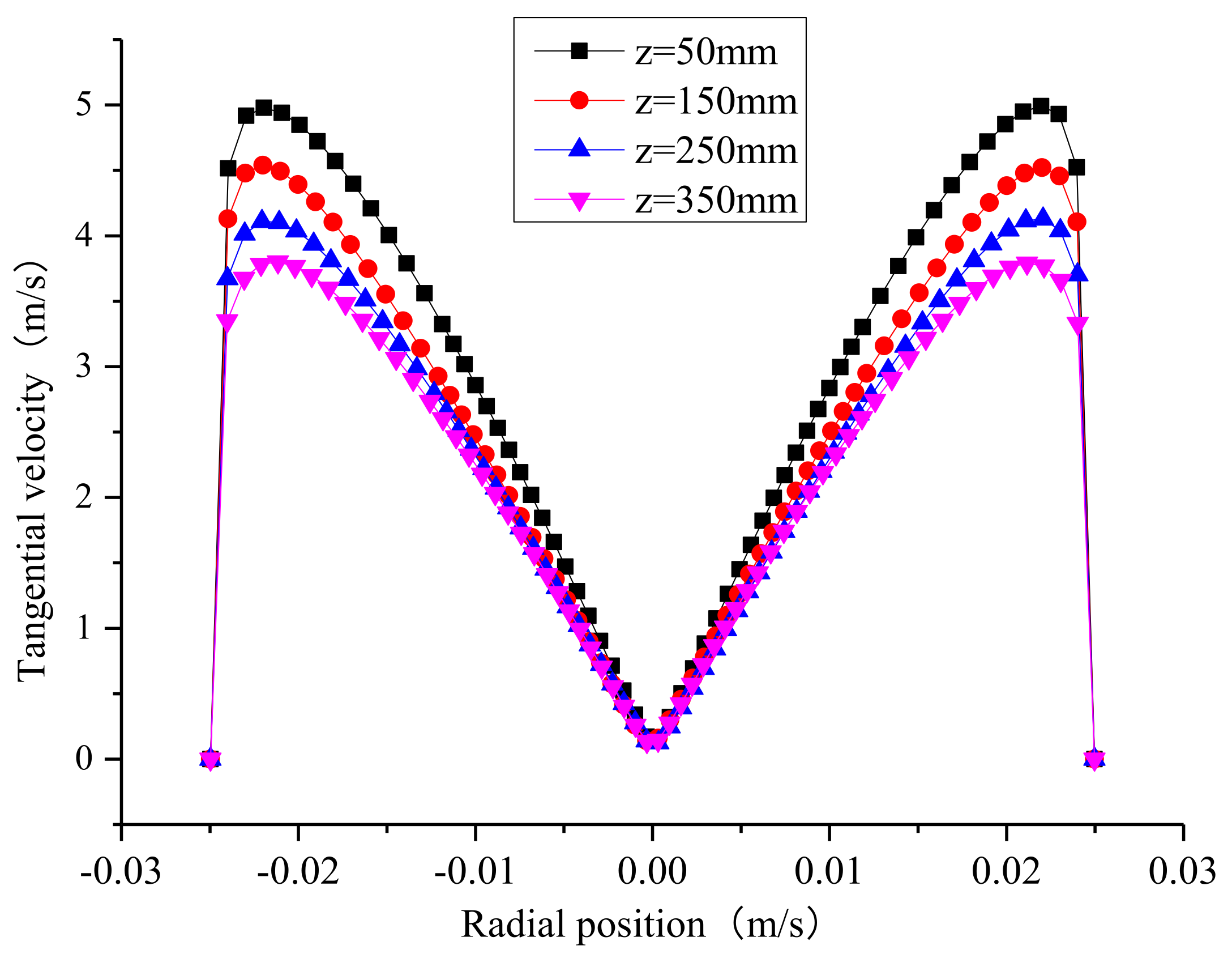
Tangential velocity is the largest and most important of the three velocity components. The tangential velocity determines the size of the centrifugal force in the separator, which has an important effect on the separation ability of the separator. Figure 9 shows the distribution cloud of the tangential velocity inside the separator. It can be seen that the tangential velocity presents an axisymmetric distribution in the radial direction in the swirl section. Figure 10 and Figure 11 show the distribution cloud of the tangential velocity and the radial distribution curves in different cross sections, respectively. Combing the two figures, it can be seen that the tangential velocity presents an axisymmetric distribution that is in the shape of an “M”. The tangential velocity quickly increases from zero to the maximum in the boundary layer near the wall, and it then decreases as the radius become smaller, and it reaches the minimum, which is almost close to zero. It suggests that the angular momentum experiences it greatest lost and that the swirl motion of the oil droplets is week in the center, which is conductive to the formation of a stable oil core. In the axial direction, it can be seen that the tangential velocity decreases gradually as the distance to the guide vane increases because of the friction effect of the wall, the shearing action within fluid, and the energy dissipation of the swirl, which causes the centrifugal force to decrease and makes the mixture more difficult to separate.
3.2. Pressure Field
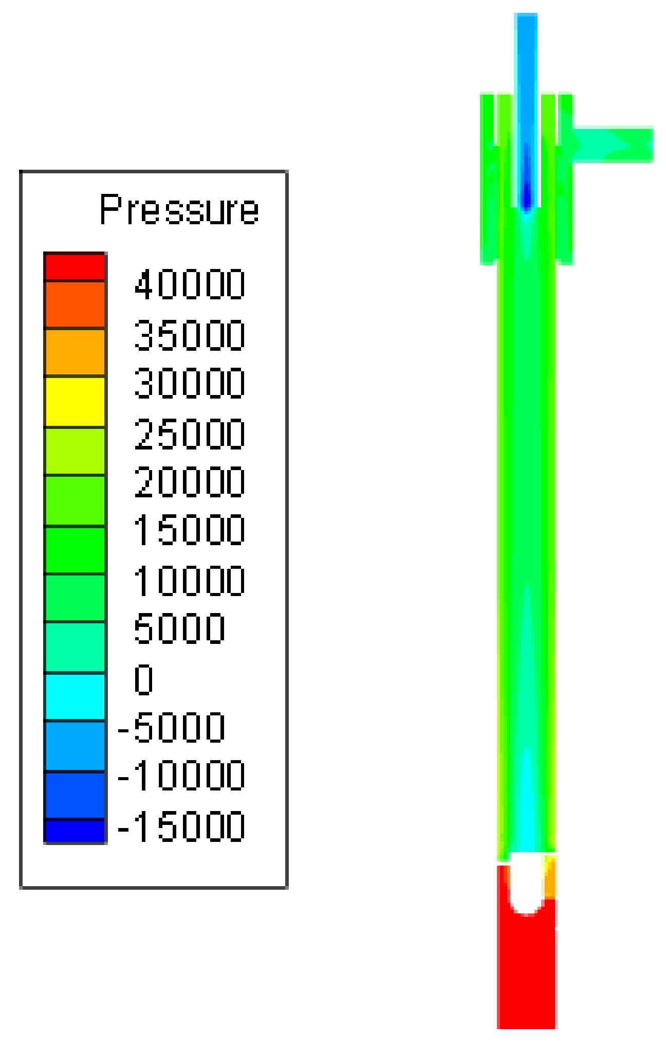
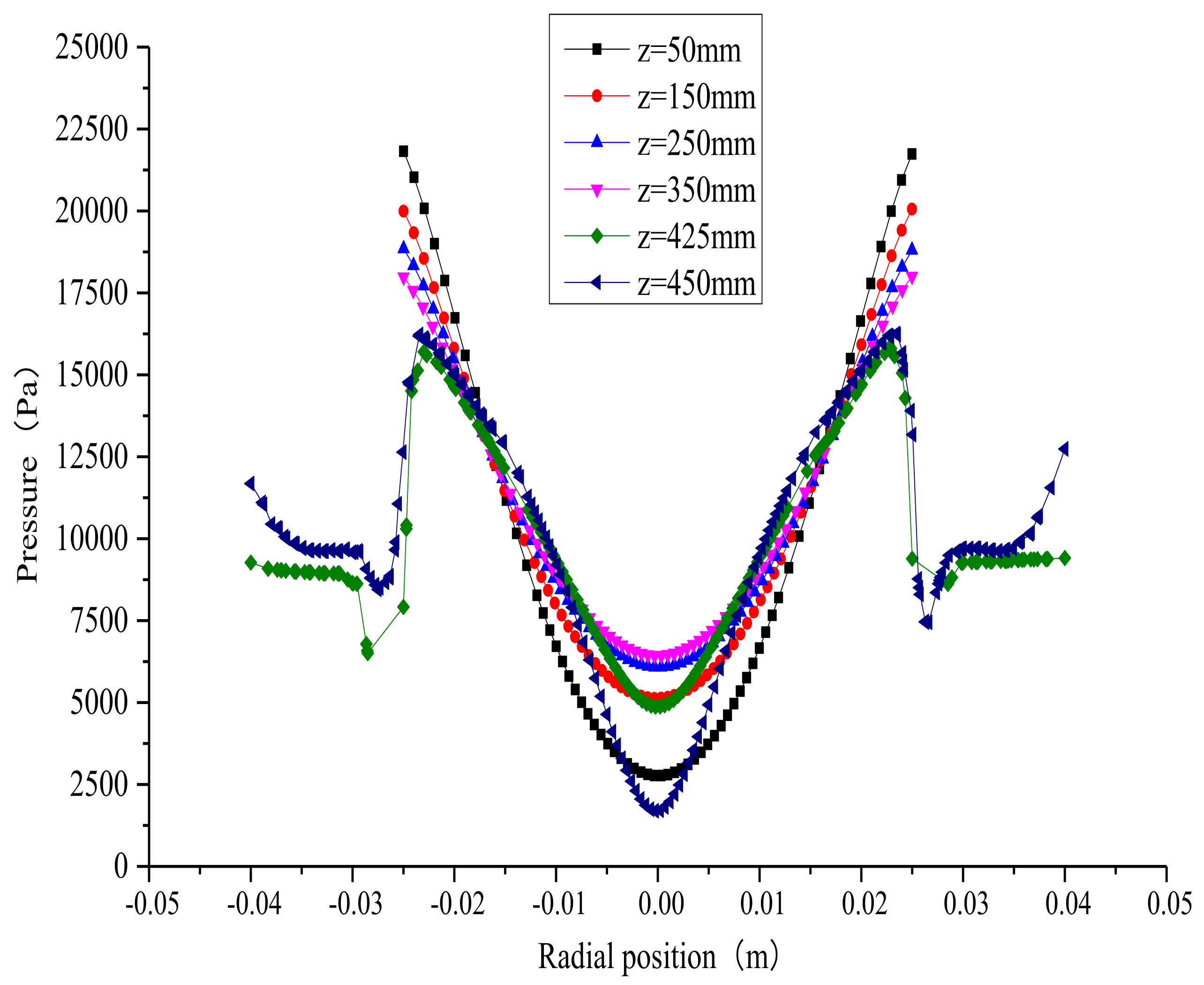
Figure 12 shows the distribution cloud of the pressure inside the separator. It can be seen that the pressure obviously decreases after the fluid flows through the guide vane. It is the guide vane that turns the pressure energy of the fluid into kinetic energy to realize the separation of oil and water. Figure 13 shows the radial distribution curves of the pressure in different cross sections. It can be seen that the pressure presents an axisymmetric distribution in the radial direction. The pressure gradually decreases as the radius in the same cross section decreases, and it reaches its minimum in the center. A certain pressure gradient in the radius comes into being because the external pressure is higher than the internal pressure. The oil phase that is under radial pressure and that is pointing towards the center has a tendency to move toward the center due to the effect of the centrifugal force, and it stokes resistance at the same time, which is also why the oil and water can be separated. The pressure drop that takes place in the slits (z = 425 mm, z = 450 mm) is larger than it is in the other positions, which enables external water to flow out from the slits.
3.3. Concentration Field
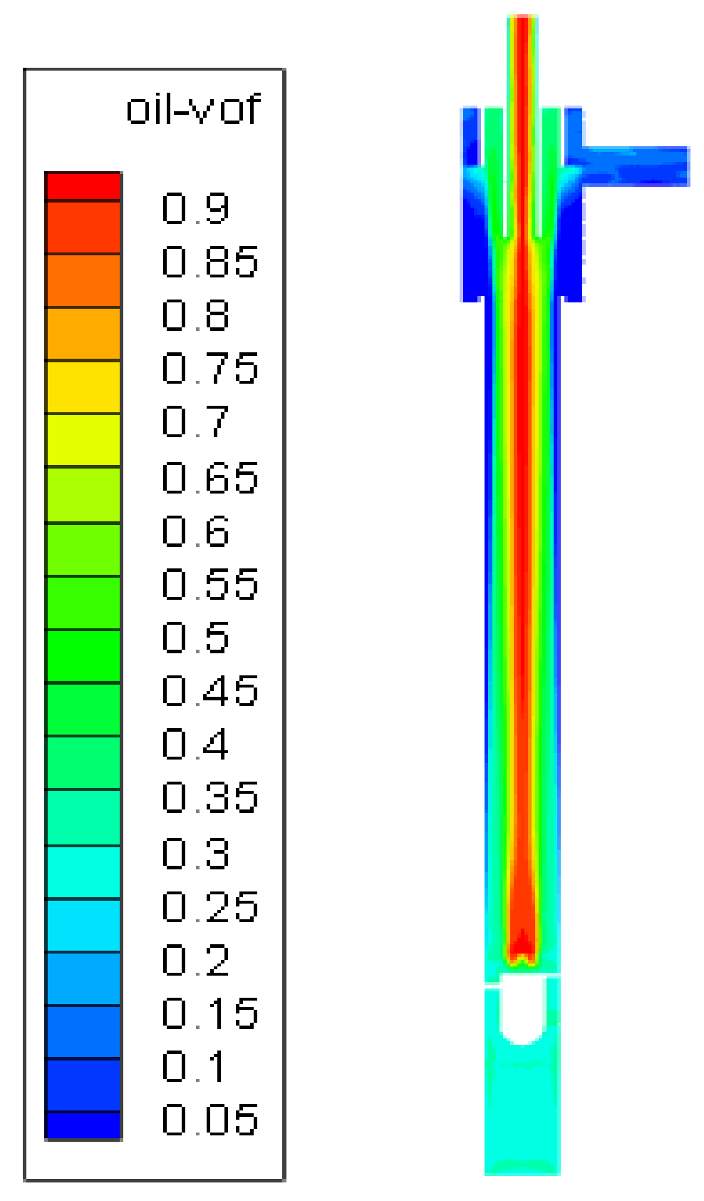
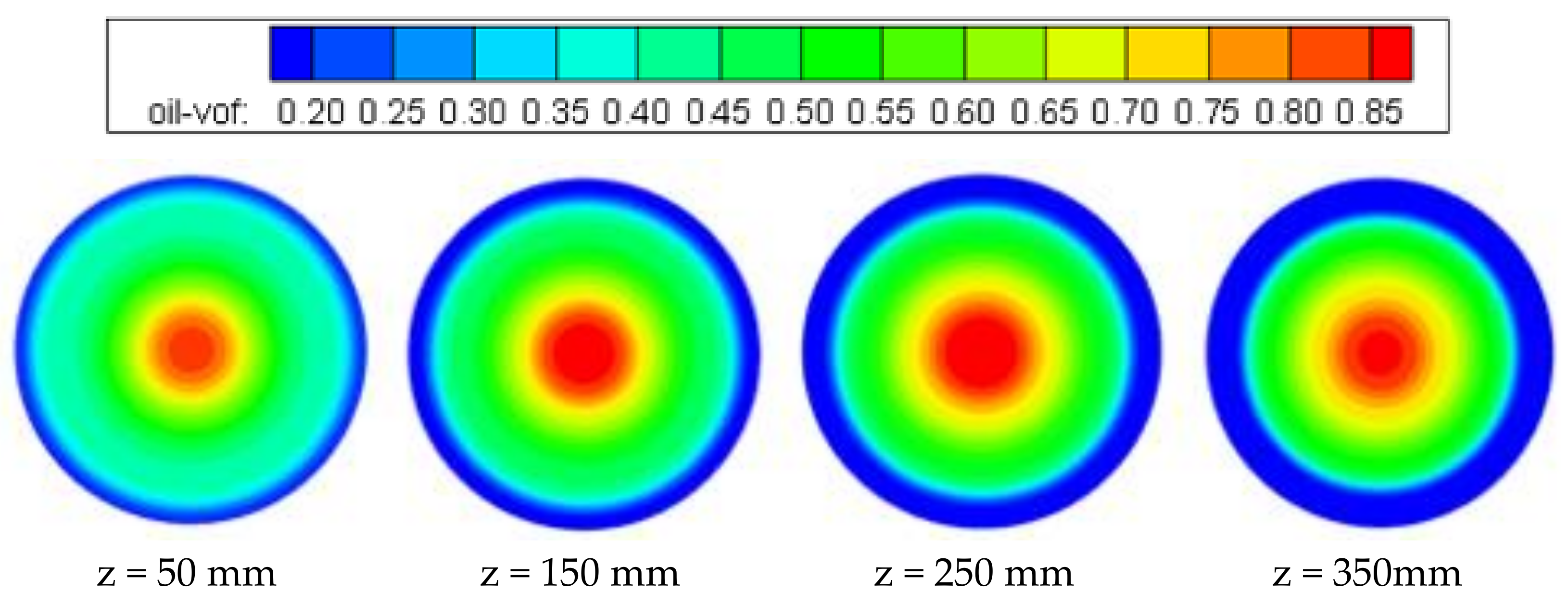
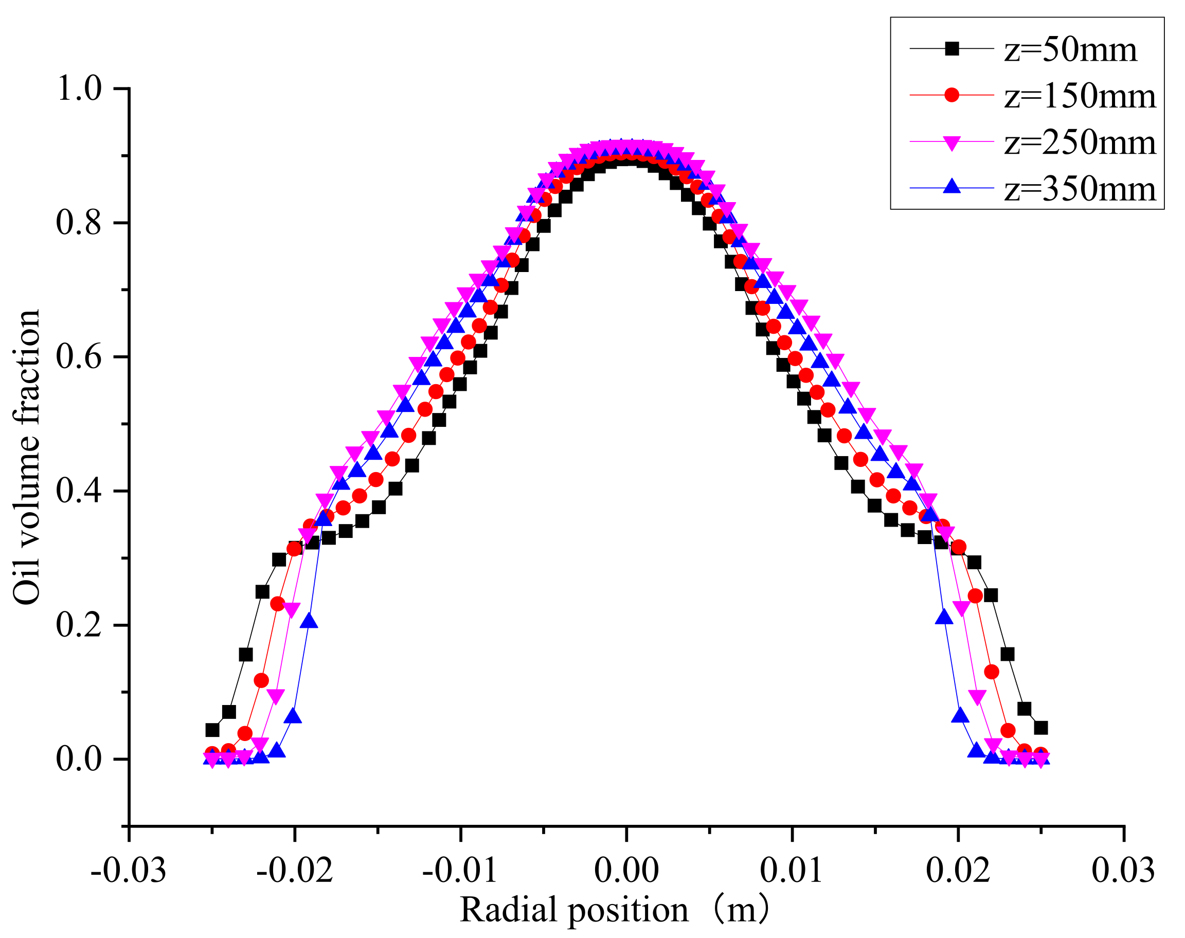
Figure 14 shows the distribution cloud of the oil volume fraction inside the separator. As shown in the figure, the mixture enters the axial inlet and develops into a high-speed rotating flow. The light oil phase that is under centripetal buoyancy and that is greater than the centrifugal force gathers together in the center due to the different densities of oil and water. An obvious oil core area forms in the center as the water phase move to the wall of separator. After entering the swirl section and undergoing stable separation, the fluid flows into the water removal section. The water around the walls flows out of the slits, and the oil core in the center flows out of the overflow tube. Figure 15 and Figure 16 show the distribution cloud of the oil concentration and the radial distribution curves in different cross sections, respectively. Combing the two figures, it can be seen that oil and water phases present an axisymmetric distribution in the radial direction after the guide vane creates the swirl. The oil phase has a high concentration in the center, and the water phase has a high concentration around the tube wall. There is an oil–water transition zone. In the axial direction, the oil concentration in the center and water concentration around the wall increases gradually as the axial distance increases. The oil core becomes stable after 250 mm, which indicates that the central oil core can be formed at a distance.
4. Conclusions
- (1)
- The effect of the guide vane that causes the swirl flow causes the tangential velocity to first increase and then decrease in the radial direction. The value reaches its minimum in the center. At the same time, the axial velocity increases as the distance to the guide vane increases. The change trend is beneficial for the oil core that begins to accumulate, and the promotion of the oil core results in the fluid flowing out of the overflow tube.
- (2)
- A pressure gradient exists in the downstream area of the guide vane that promotes the lighter oil phase as it moves to the center. The pressure energy turns into the kinetic energy after the fluid flows through the vane, which is advantageous for the separation of oil and water. The pressure drop is large in the water removal section which promotes the water phase to flow out of the slits The pressure in the overflow tube is lower than the pressure in the external area, encouraging the oil phase to flow out of the overflow outlet.
- (3)
- The oil concentration presents a symmetrical distribution, with a high concentration in the middle and a low concentration at the two sides. The oil concentration in the center and the water concentration around the walls gradually increase as the axial distance increases. A stable oil core can be formed at a distance, which indicates that the length of the swirl section should be long enough to ensure the stable oil–water separation.
Author Contributions
Conceptualization, J.K.; methodology, J.K. and Z.J.; software, Z.J.; validation, Y.C.; formal analysis, Z.J. and Y.C.; investigation, Y.C.; resources, J.K.; data curation, J.K. and Z.J.; writing—original draft preparation, Z.J. and Y.C.; writing—review and editing, J.K., Z.J. and Y.C.; visualization, Z.J.; supervision, J.K.; project administration, J.K.; funding acquisition, J.K. All authors have read and agreed to the published version of the manuscript.
Funding
This research was funded by the National Natural Science Foundation of China (No.51774311).
Institutional Review Board Statement
Not applicable.
Informed Consent Statement
Informed consent was obtained from all subjects involved in the study.
Data Availability Statement
Data sharing not applicable.
Conflicts of Interest
The authors declare no conflict of interest.
References
- Svarovsky, L. Hydrocyclones. In Solid-Liquid Separation, 4th ed.; Butterworth-Heinemann Elsevier Ltd.: Oxford, UK, 2001; pp. 191–245. [Google Scholar]
- Rojas-Solorzano, L.; Reyes, M.; Colmenares, J.; Marín, J.C.; Meléndez, A. Eulerian-Eulerian Modeling of Disperse Two-Phase Flow in a Gas-Liquid Cylindrical Cyclone. In Proceedings of the Asme Heat Transfer/fluids Engineering Summer Conference, Charlotte, NC, USA, 11–15 July 2004. [Google Scholar]
- Vieira, L.G.; Silva, D.O.; Barrozo, M.A. Effect of Inlet Diameter on the Performance of a Filtering Hydrocyclone Separator. Chem. Eng. Technol. 2016, 39, 1406–1412. [Google Scholar] [CrossRef]
- Rocha, A.; Bannwart, A.; Ganzarolli, M.; Quintella, E. Numerical Study of Swirling Flow in a Liquid-Liquid Axial Hydrocyclone Separator. In Proceedings of the 20th International Congress of Mechanical Engineering, Lake Buena Vista, FL, USA, 13–19 November 2009. [Google Scholar]
- Colman, D.; Thew, M. Cyclone separator. 1988. Available online: https://www.freepatentsonline.com/4722796.html (accessed on 26 October 2005).
- Husveg, T.; Rambeau, O.; Drengstig, T.; Bilstad, T. Performance of a deoiling hydrocyclone during variable flow rates. Miner. Eng. 2007, 20, 368–379. [Google Scholar] [CrossRef]
- Young, G.; Wakley, W.; Taggart, D.; Andrews, S.; Worrell, J. Oil-water separation using hydrocyclones: An experimental search for optimum dimensions. J. Pet. Sci. Eng. 1994, 11, 37–50. [Google Scholar] [CrossRef]
- Liu, M.; Chen, J.; Cai Han, Y.; Si, X. Oil-water pre-separation with a novel axial hydrocyclone. Chin. J. Chem. Eng. 2018, 26, 60–66. [Google Scholar] [CrossRef]
- Shi, S.Y.; Xu, J.Y. Flow field of continuous phase in a vane-type pipe oil-water separator. Exp. Therm. Fluid Sci. 2015, 60, 208–212. [Google Scholar] [CrossRef] [Green Version]
- Swanborn, R.A. A New Approach to the Design of Gas-Liquid Separators for the Oil Industry, 3rd ed.; Delft University of Technology: Delft, The Netherlands, 1988. [Google Scholar]
- Dirkzwager, M. A New Axial Cyclone Design for Fluid-Fluid Separation, 4th ed.; Delft University of Technology: Delft, The Netherlands, 1996. [Google Scholar]
- Murphy, S.; Delfos, R.; Pourquie, M.J.B.M.; Olujić, Ž.; Jansens, P.J.; Nieuwstadt, F.T.M. Prediction of strongly swirling flow within an axial hydrocyclone using two commercial CFD codes. Chem. Eng. Sci. 2007, 62, 1619–1635. [Google Scholar] [CrossRef]
- Zhan, M.; Cheng, X.; Yang, W.; Zhang, F.; Guo, P.; Shen, Q. Numerical investigation on the swirler parameters for an axial liquid-liquid hydrocyclone. In IOP Conference Series: Earth and Environmental Science; IOP Publishing: Bristol, UK, 2021; p. 012210. [Google Scholar]
- Hamza, J.; Al-Kayiem, H.; Lemma, T. Experimental Investigation of the Separation Performance of Oil/Water Mixture by Compact Conical Axial Hydrocyclone. Therm. Sci. Eng. Prog. 2020, 17, 100358. [Google Scholar] [CrossRef]
- Song, M.H. Design and Structure Optimization on a New Vane-Guided Hydrocyclone. Master’s Thesis, Northeast Petroleum University, Daqing, China, 2013. [Google Scholar]
- Thew, M. Hydrocyclone redesign for liquid-liquid separation. Chem. Engr. 1986, 7, 17–23. [Google Scholar]
- Lu, Z.H.; Wei, C.D.; Wu, Q.L. Investigation on the Characteristics of Oil-Water Separation in Different Structural Cyclones. National Symposium on Water Dynamics. 2014. Available online: https://kns.cnki.net/kcms/detail/detail.aspx?dbcode=CPFD&dbname=CPFD0914&filename=SLDX201408005021&uniplatform=NZKPT&v=5u1PxGGINZXjpdeU8ZF51dnaCJOV3hGRF7TSxG9_oNhk4czxTkmCQNW0UoYIdSLhcJsewtGM0-8%3d (accessed on 26 October 2005).
- Jin, X.; Jin, Y.; Wang, Z.; Wang, J. Effect of Vessel Geometry on the Separation Performance of the Axial Flow Type Gas-liquid Cyclone Separator. Fluid Machinery. 2008. Available online: https://kns.cnki.net/kcms/detail/detail.aspx?dbcode=CJFD&dbname=CJFD2008&filename=LTJX200801004&uniplatform=NZKPT&v=w_sZ0ZEF0nUIJx1Tm96QDhHilawruyTcfhEw9cg4PiVcgyJsBw9XqojcylQq9y9l (accessed on 26 October 2005).
- Chu, L.; Chen, W. Research on the solid-liquid two-phase flow field in hydrocyclone. Appl. Mech. Mater. 2014, 672–674, 961–967. [Google Scholar]
- FLUENT. User’s Guide; Fluent Inc.: Lebanon, NH, USA, 1998. [Google Scholar]
- Nieuwstadt, F.; Dirkzwager, M. A Fluid Mechanics Model for an Axial Cyclone Separator. Ind. Eng. Chem. Res. 1995, 34, 3399–3404. [Google Scholar] [CrossRef]
- Shi, S.; Wu, Y.; Luo, C. Study about a kind of vane-type pipe separator for oil-water separation. In Proceedings of the 23rd National Water Dynamics Symposium, Xi’an, Shaanxi, China, 19–24 September 2011; p. 10. [Google Scholar]
- Shi, S.; Liu, M.; Luo, C.; Wang, S.; Zhong, X.; Gao, M.; CAS. Preliminary Study about the Structure Optimization of a New Vane-Type of Pipe Separator for Oil-Water Separation; Shipbuilding of China: Shanghai, China, 2012. [Google Scholar]
- You, J.L. Structure Design of Inner-Cone Type Gas-Liquid Cylindrical Cyclone and Its Optimization. Master’s Thesis, Northeast Petroleum University, Daqing, China, 2012. [Google Scholar]
- Narasimha, M.; Sripriya, R.; Banerjee, P. CFD modelling of hydrocyclone—Prediction of cut size. Int. J. Miner. Process. 2005, 75, 53–68. [Google Scholar] [CrossRef]
- Jiang, M.; Yong-Shan, L.; Bao-Rui, X.; Zhao, L. Optimization of Operational Parameters of Three-phase Hydrocyclone for Axial Degassing and Desanding. Chem. Eng. Mach. 2015, 42, 68–71. [Google Scholar]
- Frana, F.; Rosa, E.; Banmvart, A. Hydrodynamic Studies on a Cyclonic Separator. In Proceedings of the Offshore Technology Conference, Houston, TX, USA, 6 May 1996. [Google Scholar]
- Cui, H. Research on the Separation Mechanism and Working Performance of Gas-Water Spiral Separator. Master’s Thesis, Daqing Petroleum Institute, Daqing, China, 2010. [Google Scholar]
- Yan, Z.; Xiang, L.; Dong, T. Simplified calculation of pressure drop in spiral separator. Chem. Eng. 2004, 2004, 24–28. [Google Scholar]
- Miao, Q.; Yuan, H. Test research and analysis on asymmetry of flow within liquid-liquid hydrocyclones. Oil Field Equip. 2005, 2005, 93–95. [Google Scholar]
- Yong, L.; Liu, Z.; Yi, A. A brief introduction to Fluent—A general purpose CFD code. J. Hydrodyn. 2001, 2001, 254–258. [Google Scholar]
Figure 1.
Structure of the axial hydrocyclone separator (unit: mm).

Figure 2.
Three-dimensional vane model.

Figure 3.
Mesh model of the separator.

Figure 4.
Mesh model of the vane.

Figure 5.
Distribution cloud of axial velocity inside the separator.

Figure 6.
Backflow phenomenon vector image.

Figure 7.
Distribution cloud of axial velocity in different cross sections.

Figure 8.
Radial distribution curves of axial velocity in different cross sections.

Figure 9.
Distribution cloud of tangential velocity inside the separator.

Figure 10.
Distribution cloud of tangential velocity in different cross sections.

Figure 11.
Radial distribution curves of tangential velocity in different cross sections.

Figure 12.
Distribution cloud of pressure inside the separator.

Figure 13.
Radial distribution curves of pressure in different cross sections.

Figure 14.
Distribution cloud of oil concentration inside the separator.

Figure 15.
Distribution cloud of oil concentration in different cross sections.

Figure 16.
Radial distribution curves of oil concentration in different cross sections.


Table 1.
Test and verification of grid independence.
| Grid Number | Separation Efficiency/% | Pressure Drop of Overflow Outlet/MPa | Pressure Drop of Bottom-Flow Outlet/MPa |
|---|---|---|---|
| 524,506 | 87.44 | 0.16 | 0.14 |
| 764,281 | 89.28 | 0.18 | 0.15 |
| 852,458 | 90.12 | 0.18 | 0.15 |
| 1,009,426 | 90.27 | 0.18 | 0.15 |
Publisher’s Note: MDPI stays neutral with regard to jurisdictional claims in published maps and institutional affiliations. |
© 2021 by the authors. Licensee MDPI, Basel, Switzerland. This article is an open access article distributed under the terms and conditions of the Creative Commons Attribution (CC BY) license (https://creativecommons.org/licenses/by/4.0/).
Share and Cite
MDPI and ACS Style
Kou, J.; Jiang, Z.; Cong, Y. Separation Characteristics of an Axial Hydrocyclone Separator. Processes 2021, 9, 2288. https://0-doi-org.brum.beds.ac.uk/10.3390/pr9122288
AMA Style
Kou J, Jiang Z, Cong Y. Separation Characteristics of an Axial Hydrocyclone Separator. Processes. 2021; 9(12):2288. https://0-doi-org.brum.beds.ac.uk/10.3390/pr9122288
Chicago/Turabian StyleKou, Jie, Zhaoming Jiang, and Yiying Cong. 2021. "Separation Characteristics of an Axial Hydrocyclone Separator" Processes 9, no. 12: 2288. https://0-doi-org.brum.beds.ac.uk/10.3390/pr9122288
Note that from the first issue of 2016, this journal uses article numbers instead of page numbers. See further details here.