Coordinate Measuring Machine Probes Effect during Inner Thread Position Measurement †

1
Faculty of Engineering and Information Technology, “George Emil Palade” University of Medicine, Pharmacy, Science, and Technology of Targu Mures, 540088 Târgu Mureș, Romania
2
CIEMatricon S.A., 540394 Targu Mures, Romania
*
Author to whom correspondence should be addressed.
†
Presented at the 14th International Conference on Interdisciplinarity in Engineering—INTER-ENG 2020, Târgu Mureș, Romania, 8–9 October 2020.
Proceedings 2020, 63(1), 55; https://0-doi-org.brum.beds.ac.uk/10.3390/proceedings2020063055
Published: 28 December 2020
(This article belongs to the Proceedings of The 14th International Conference on Interdisciplinarity in Engineering—INTER-ENG 2020)
Abstract
:Starting from the idea of improving Coordinate Measuring Machines’ (CMM) measurement strategy for inner thread locations, we developed a new method which increases the accuracy of measurements and takes us closer to the pitch diameter. This article will analyze this new method by testing different touching probes configurations for different thread sizes. The objective is to identify the best probe configuration to be used in the measurements of different inner thread sizes.
1. Introduction
The evolution of technology creates the need to improve the response during production processes; to do this, the process control must be faster and have increased accuracy. In this research, we are focused on thread position measurement strategy solutions, because even if the CMM software developer elaborate solutions for regulated and non-regulated surfaces, the small inner threads (ex. M3 to M12) strategy were left behind. The actual measurement strategies that are used to measure inner threads on the CMM are divided in two categories. In the first, we can use the inner cylinder CMM strategy; here, we can chose different types of measurement, like more circles on different levels or an elliptical rotation with a pitch indexation/revolution or tangent lines to indicate the minimum or maximum diameter. In the second method, we use special pins, which will auto-center on the inner thread. Each method has pro and cons, and the actual paperwork is focused on the first measurement strategy, where improvements were made. The second strategy’s advantages are the accuracy and the repeatability, the disadvantages are that the pins are very expensive and, overtime, the auto-centering will decrease, and repeatability will decrease, which will give bad measurement results. The CMM measurement accuracy is composed of two important categories: correct measurement strategy and correct tool used [1]. To improve the measurement accuracy, we elaborate a method where the measurement tool will scan the inner thread. This method was developed to improve the measurement strategy for this type of measurement. The second approach is to identify the best tool that can be used for different thread dimensions.
2. Material and Methods
The measurements were performed on a Hexagon Global Advantage 122,210 Coordinate Measurement Machine edition 2018, Accuracy: 2.1 um + L/333, Drive Unit: HH-A-T-5 + (SP25M + SM25-3 + SH25-3)*equipped with a steel probe with an active side made of a ruby ball with different diameters: 2, 3, 4 and 5 mm. Software of CMM is PC-Dmis 2019R1. Measurement speed was set to 4 mm/s.
For the thread profile evaluation, a MahrMahrsurfXC2 Contour measurement machine edition 2017 with CD120 Drive unit was used, equipped with probe PCV 350 ± 9 with a 25 um active side of the probe, with an accuracy of 0.35 um. Measurement speed was set to1 mm/s.
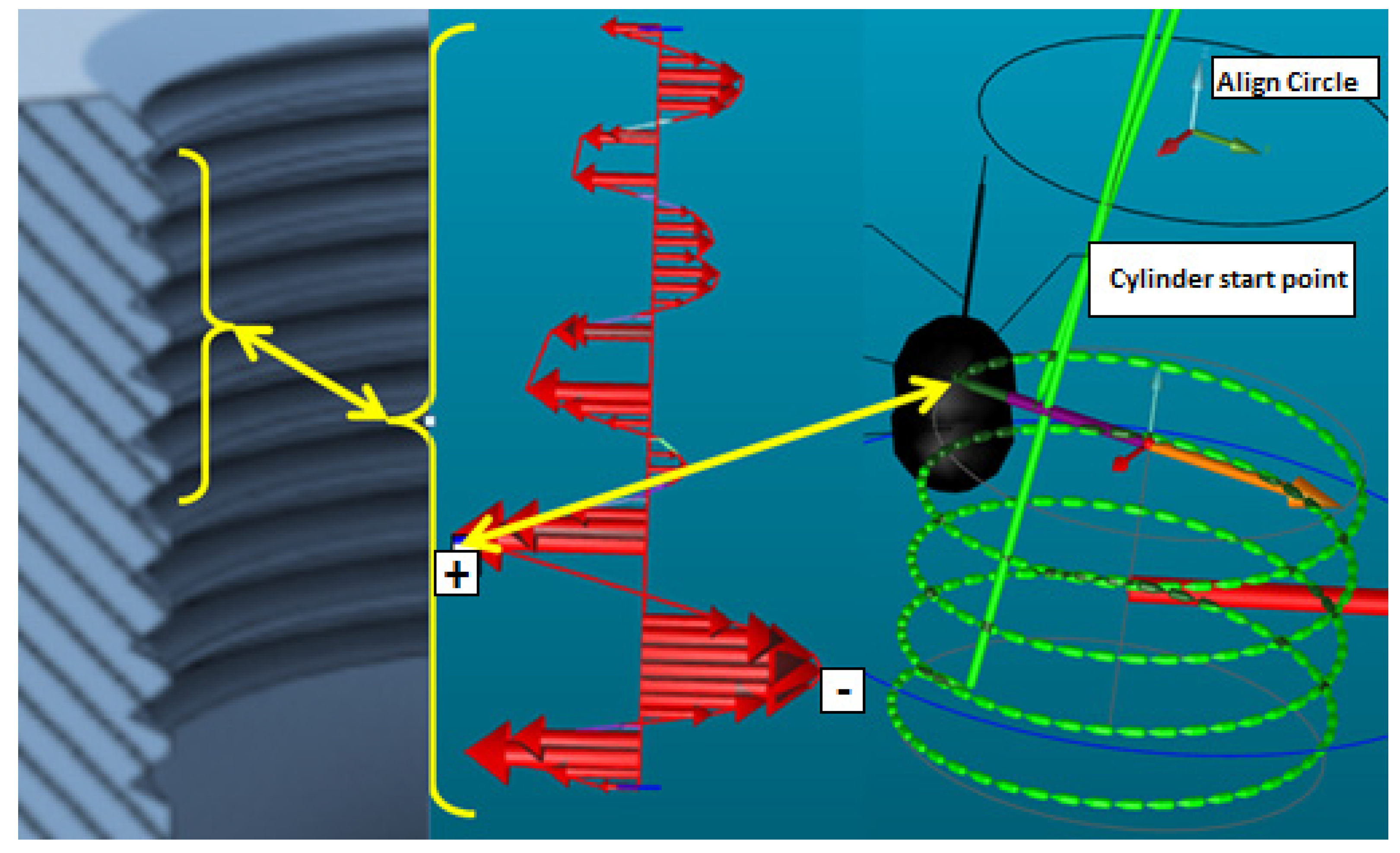
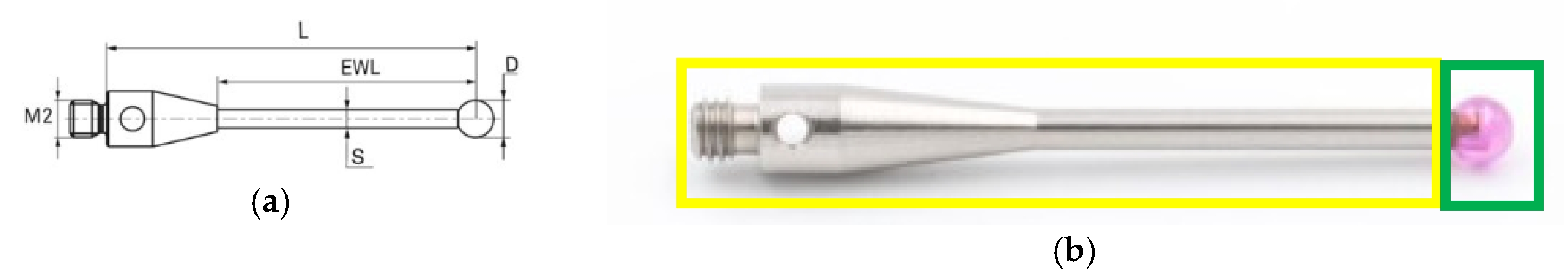
The method that we used to make this evaluation consisted of measuring the thread as close as possible to the pitch diameter; this can be done by evaluating the form of the inner surface of the thread and identifying the closest point to the pitch diameter. The measurement will begin from this point and will measure a cylinder with a revolution movement that follows the pitch of the thread; more details can be observed in Figure 1. In the actual research, we connected the measuring probe diameter and the measurement strategy to measure a specific thread size. The probe configuration and dimensions are standardized, and therefore is possible to measure metric threads between M4 and M12 without a wide variety of probes. The dimensions of a probe are formed from an active area and inactive areas; examples are presented in Figure 2, where we can observe the active area represented by (D), the diameter of the probe, and inactive areas like M2, the metric thread used to assemble the probe, L, which represents the length of the probe that must be introduced in the CMM software to can make automatic calibrations, EWL, which is the length of the active ball support which, in combination with S, which represents the diameter of the EWL, will have a big impact when we chose the measurement probe. The measurement is done taking into consideration that characteristic “S” of the probe will not be in contact with the thread; the probe must be in contact only with the active side when measuring the inner thread.
3. Results and Discussion
Measurements were made for two metric threads, M6 and M8; for this, we used probes with an active sphere diameter from ø 2 to ø 5 mm. The results are focused on the pitch diameter and the repeatability and accuracy of thread location. Having all this information we investigate several issue and opportunities to do it right and here are some quote’s from our refererences: “The basis of the direct method of measuring the position of the threaded holes was that the probe was led directly into the threaded hole and then were scanned the certain number of points, from these points cylinder by least-squares method was created. After that, the position of the axis of the cylinder to a reference hole was determined” [3]. “The methods presented apply only to determining the position of a threaded hole. The threads themselves, along with the minor diameter, should be checked with a thread gage with one exception. If they are large enough for a styli to fit inside and scan the surface, there are techniques discussed elsewhere that will help. None of the methods below will be able to calculate the size reliably (except scanning may get a reasonably close minor diameter) unless the pitch surface of the thread is accessible to a stylus” [4]. “Another problem measuring threads is if the threads on the CAD don’t match the physical part, you’ll have trouble finding the thread. Our part that we intended to measure threads on had a different start and end than what the model shows. So when I picked points along the major on the CAD, the CMM probed those points on the minor on the part. Not good. So we had to keep using threaded gages. Do the threads still work? yes they do, CAD is just the reference and I hear threads are a little difficult to model. Also we have multiple machines making the same part and there is start and end variation from those machines. So you’ll not be able to use the exact same program/routine across CNC machines. First thing you have to do is be able find the thread with the CMM” [5].
3.1. Metric 6 Measurement Results
3.1.1. Diameter Analysis
All diameter measurements are presented in Table 1. The results indicate that probe diameter ø 2 mm is the closest to the pitch diameter. If we consider going below this diameter, we risk that the part will be in contact with the inactive side of the probe.
3.1.2. Location Analysis
We calculate the true position (TP) for the measurement so that we have a simple interpretation of the results. Table 2 presents the measurement related to the diameter of the probe. Measurements made with probe ø 2 indicate the best results, next is probe ø 3 and the worst is probe ø 4.
3.2. Metric 8 Measurement Results
3.2.1. Diameter Analysis
All diameter measurements are presented in Table 3. The results indicate that probe diameter ø 2 and ø 3 mm is the closest to the pitch diameter. If we consider going below to this diameter, we will risk being in contact with the inactive side of the probe.
3.2.2. Location Analysis
We calculate the true position (TP) for the measurement so that we have a simple interpretation of the results. Table 4 presents the measurement related to the diameter of the probe. Measurements made with probe ø 5 indicate the best results, next is probe ø 2 and ø 3 and the worst is probe ø 4.
4. Conclusions
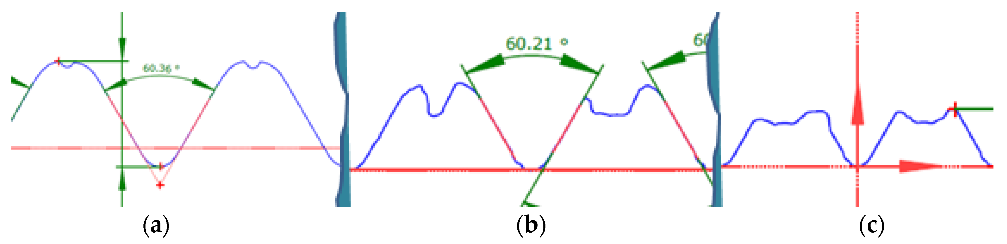
The measurement results indicated in Table 1 and Table 3 show us that a small probe diameter can be a good solution to be closer to the pitch diameter; these results can also be seen in Table 2 and Table 4. In these tables we measure the true position, and the evaluation indicates the same results as in Table 1 and Table 2: a small probe is more accurate for this measurement strategy than a large probe. All the results presented above are made for a part where the machining tool is new. In the serial production, the regular measurement strategy remains the same for a CMM program, but the part will modify continuously during the cycle time of the project: wear of the mold, wear of the gages, wear of the machining tools, setup of new molds, etc., will all increase the chance of measurement errors. Knowing this, we created the variable strategy model where the thread is evaluated every time, and here the configuration of the probe also has a big impact on the final inspection of the part measurement. If we choose a probe with a small diameter, than we risk to measuring with the inactive part of the probe, whereas if we choose a probe with a large diameter, we will not measure the desired location. The wear of the machining tools (see Figure 3) facilitates the bad segment of thread and this will decrease the measurement availability area. The material defects can also facilitate a wrong measurement interpretation; the big porosity inside the threads must be identified before the measurement.
If we use the correct measurement strategy and the correct measurement tool, we can increase the amount of correct measurements too. The pitch diameter gives us the most accurate and the most correct inner thread location and the ax given by this measurement indicates a correct location of the thread. We can find a false location of the threads if we are not focused on measuring these characteristics.
Acknowledgments
This work was partially supported by the UMFST “George Emil Palade” Quality Engineering and Digital Manufacturing Research Center.
Conflicts of Interest
The authors declare no conflict of interest.
References
- Serban, P.; Peti, F. Coordinate Measuring Machine thread position measurement analysis. In Proceedings of the IOP Conference Series: Materials Science and Engineering, Annual Session of Scientific Papers—IMT Oradea, Oradea, Romania, 28–29 May 2020; IOP Publishing Ltd.: Bristol, UK, 2020; Volume 898. [Google Scholar]
- Ahmet Yüksel, İ.; OytunKılınç, T.; Berk Sönmez, K.; ÖnAktan, S. Comparison of internal and external threads pitch diameter measurement by using conventional methods and CMM’s. In Proceedings of the 19th International Congress of Metrology, Paris, France, 24–26 September 2019; p. 09001. [Google Scholar]
- Martikáň, P.; Drbúl, M.; Holubják, J.; Mrázik, J.; Joch, R. The issue of determining the geometric position deviation of the threaded holes. Adv. Sci. Technol. Res. J. 2016, 10, 47–52. [Google Scholar] [CrossRef]
- Measuring a Pitch. Available online: https://www.pcdmisforum.com/ (accessed on 25 June 2020).
- How Do I Measure a Threaded Hole? Available online: www.hexagon.com (accessed on 25 June 2020).
Figure 1.
Evaluation steps to measure the inner thread.

Figure 2.
Probe configuration and dimensions: (a) Probe characteristics; (b) Characteristic marked with yellow are inactive and with green are active. “Pitch diameter measurements of internal threads are more complicated than external threads [2] due to construction of internal thread which does not allow easy probing like external threads”.

Figure 3.
Thread section profile for a new tool (a), a used tool (b) and a broken tool (c).


Table 1.
Diameters of the thread resulted by measuring using 3 probes and 5 measurements.
| M6X1/Min5.35/Max5.50 | |||||
|---|---|---|---|---|---|
| Probe | 1 | 2 | 3 | 4 | 5 |
| ø 2 mm | 5.194 | 5.195 | 5.195 | 5.194 | 5.193 |
| ø 3 mm | 5.134 | 5.133 | 5.135 | 5.134 | 5.134 |
| ø 4 mm | 5.091 | 5.092 | 5.096 | 5.091 | 5.092 |
Table 2.
TP of the thread resulted by measuring using 3 probes and 5 measurements.
| M6X1 | ||||||
|---|---|---|---|---|---|---|
| Probe | TP | 1 | 2 | 3 | 4 | 5 |
| ø 2 mm | ø dev | 0.014 | 0.016 | 0.016 | 0.016 | 0.016 |
| ø 3 mm | ø dev | 0.020 | 0.019 | 0.019 | 0.018 | 0.019 |
| ø 4 mm | ø dev | 0.130 | 0.125 | 0.123 | 0.126 | 0.124 |
Table 3.
Diameters of the thread, found by measuring using 4 probes and 5 measurements.
| M8X1/Min7.188/Max7.348 | |||||
|---|---|---|---|---|---|
| Probe | 1 | 2 | 3 | 4 | 5 |
| ø 2 mm | 7.142 | 7.151 | 7.155 | 7.151 | 7.151 |
| ø 3 mm | 7.082 | 7.083 | 7.083 | 7.083 | 7.083 |
| ø 4 mm | 7.049 | 7.049 | 7.050 | 7.050 | 7.050 |
| ø 5 mm | 7.001 | 7.003 | 7.021 | 6.987 | 7.021 |
Table 4.
TP of the thread, found by measuring using 4 probes and 5 measurements.
| M8X1 | ||||||
|---|---|---|---|---|---|---|
| Probe | TP | 1 | 2 | 3 | 4 | 5 |
| ø 2 mm | ø dev | 0.066 | 0.069 | 0.072 | 0.071 | 0.072 |
| ø 3 mm | ø dev | 0.067 | 0.069 | 0.070 | 0.071 | 0.071 |
| ø 4 mm | ø dev | 0.105 | 0.105 | 0.103 | 0.103 | 0.103 |
| ø 5 mm | ø dev | 0.052 | 0.054 | 0.066 | 0.059 | 0.068 |
Publisher’s Note: MDPI stays neutral with regard to jurisdictional claims in published maps and institutional affiliations. |
© 2020 by the authors. Licensee MDPI, Basel, Switzerland. This article is an open access article distributed under the terms and conditions of the Creative Commons Attribution (CC BY) license (http://creativecommons.org/licenses/by/4.0/).
Share and Cite
MDPI and ACS Style
Peti, F.; Serban, P. Coordinate Measuring Machine Probes Effect during Inner Thread Position Measurement. Proceedings 2020, 63, 55. https://0-doi-org.brum.beds.ac.uk/10.3390/proceedings2020063055
AMA Style
Peti F, Serban P. Coordinate Measuring Machine Probes Effect during Inner Thread Position Measurement. Proceedings. 2020; 63(1):55. https://0-doi-org.brum.beds.ac.uk/10.3390/proceedings2020063055
Chicago/Turabian StylePeti, Ferencz, and Petru Serban. 2020. "Coordinate Measuring Machine Probes Effect during Inner Thread Position Measurement" Proceedings 63, no. 1: 55. https://0-doi-org.brum.beds.ac.uk/10.3390/proceedings2020063055