Achieving a Toothed Gear on Presses †
by
 , , ,
, , ,
Marius Tintelecan
1,* ,
,
Dana-Adriana Iluțiu-Varvara
1, 
Oscar Rodriguez-Alabanda
2,
Ioana Monica Sas-Boca
1 ,
,
Ionuț Marian
1 and
Aristides Santana Martinez Gustavo
3 1
Department of Materials Science and Engineering, Technical University of Cluj-Napoca, 100114 Cluj Napoca, Romania
2
Department of Mechanical Engineering, University of Cordoba, Medina Azahara Avenue, 5, 14071 Cordoba, Spain
3
Engineering School of Lorena, University of São Paulo-USP, Lorena 12602-810, Brazil
*
Author to whom correspondence should be addressed.
†
Presented at the 14th International Conference on Interdisciplinarity in Engineering—INTER-ENG 2020, Târgu Mureș, Romania, 8–9 October 2020.
Proceedings 2020, 63(1), 57; https://0-doi-org.brum.beds.ac.uk/10.3390/proceedings2020063057
Published: 28 December 2020
(This article belongs to the Proceedings of The 14th International Conference on Interdisciplinarity in Engineering—INTER-ENG 2020)
Abstract
:This paper presents a device that, in final connection with presses, allows toothed gear (with a crown similar to a toothed wheel with right teeth) to be achieved by hot deformation starting from a cylindrical steel bar. For this, finite element simulations were performed in Forge software. The proposed device has 23 rollers, so for the simulation process, a slice representing a part (the 23rd) of a circle which simplifies the essential functionality of this device was taken into consideration.
1. Introduction
From the start of this research problem, it should be noted that the semi-finished product was obtained through a plastic forming process (pressing) by an equipment with 23 forming rollers [1]. The symmetry axis of the set is collinear to the symmetry axis of the final toothed gear, so we subjected a slice which is the 46th part from 360°, namely 7.8°, in the simulations. Additionally, we tried to quantify the implications of operating the press punch on the designed and assembled toothed gear wheel.
A mesh network was built for each slice, and the corresponding plastic deformation equations were applied in each of them. Through this research methodology, we noticed how each simulated slice of 7.8° was affected overall, so we reached the necessary conclusions that led us to make the necessary changes in the whole assembly, and finally we saw how the whole set behaved.
The technical parameters of this plastic deformation process were deduced. It was proven that the technical feasibility for the manufacture of toothed gear wheels through this method is clearly superior to the classical method which involves milling, especially due to the significantly higher productivity of the proposed process and the material saving, in addition to the advantage of toothed gear wheels obtained with continuous fiber, who are much more resistant from a mechanical point of view.
2. The Pressing
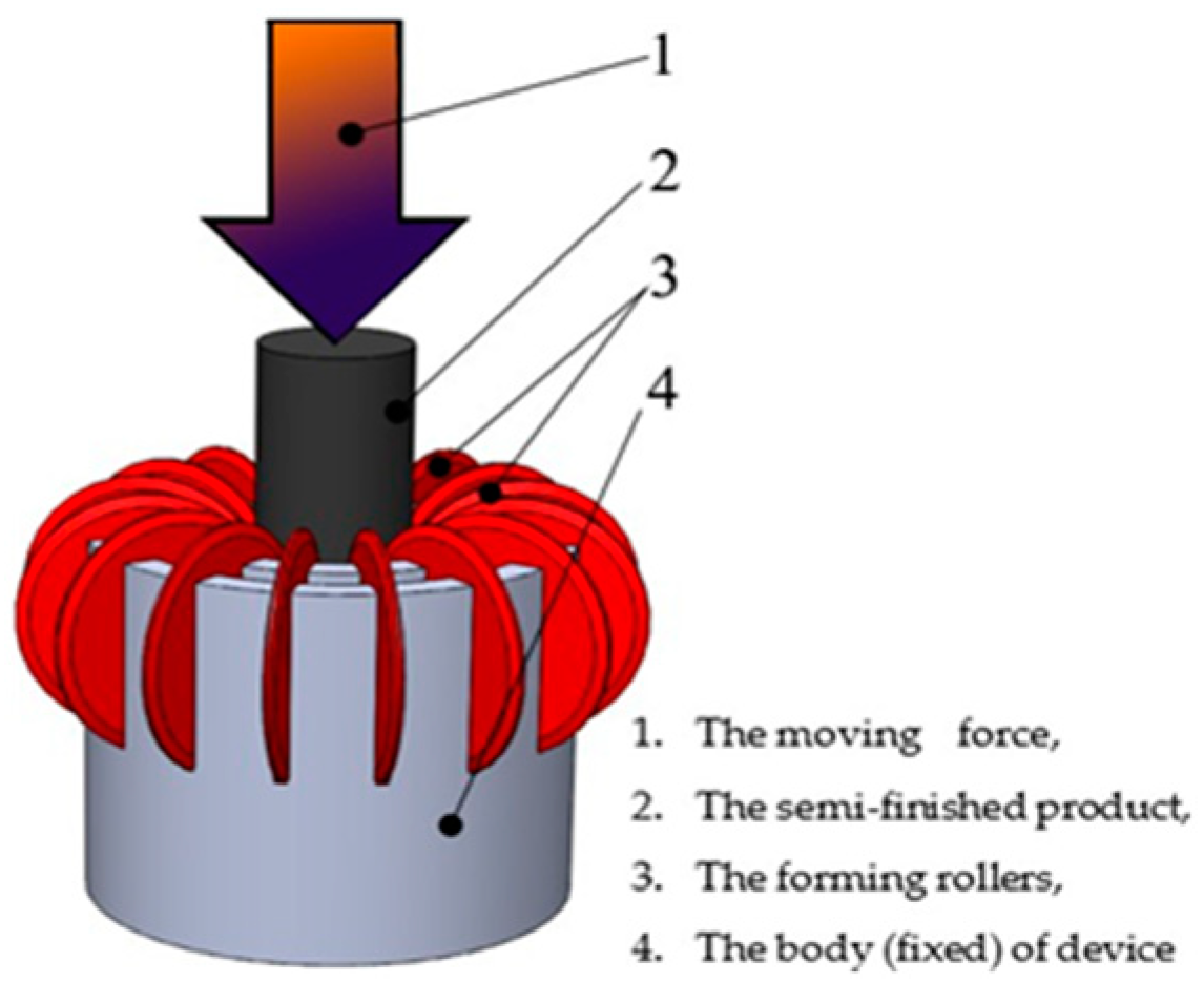
We started from the idea of making a toothed gear by pressing a cylindrical semi-finished product, made by drawing [2,3], through a roller device. In a specific case, we decided that the device should consist of 23 deformation rollers and a body (fixed) on which these rollers are assembled. The design was created using a CAD software: SolidWorks (see Figure 1). It must be noted that the device was made only for research, being intended for the realization of a gear with straight teeth having a certain number of teeth (23) and a certain circular pitch, respectively.
For practical, concrete cases, such a device can be built for each desired value of the number of teeth and the circular pitch “p” of the final toothed gear.
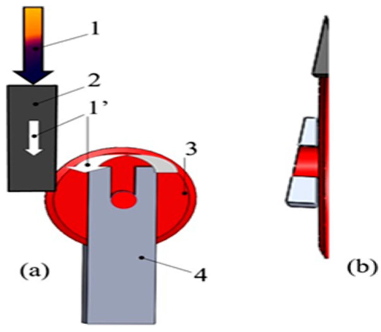
The toothed gear achieved device, built, has 23 deforming rollers, for simulation using the 46th part of a virtual circle, which has in the center the longitudinal axis of symmetry of the semi-finished product, thus being similar to a slice with peak angle of 7.8° as is shown in Figure 2.
This simplification was used to speed up the analysis time of the simulation process. We want to mention that the simulation of the deformation process was simplified to a “slice” because the process is axisymmetric.
3. The Device Description
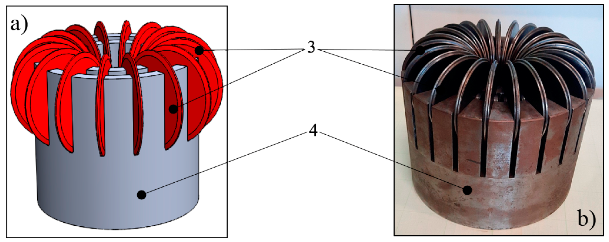
The previously proposed device was actually made to confirm the simulation results and its design and real assembly is shown in Figure 3.
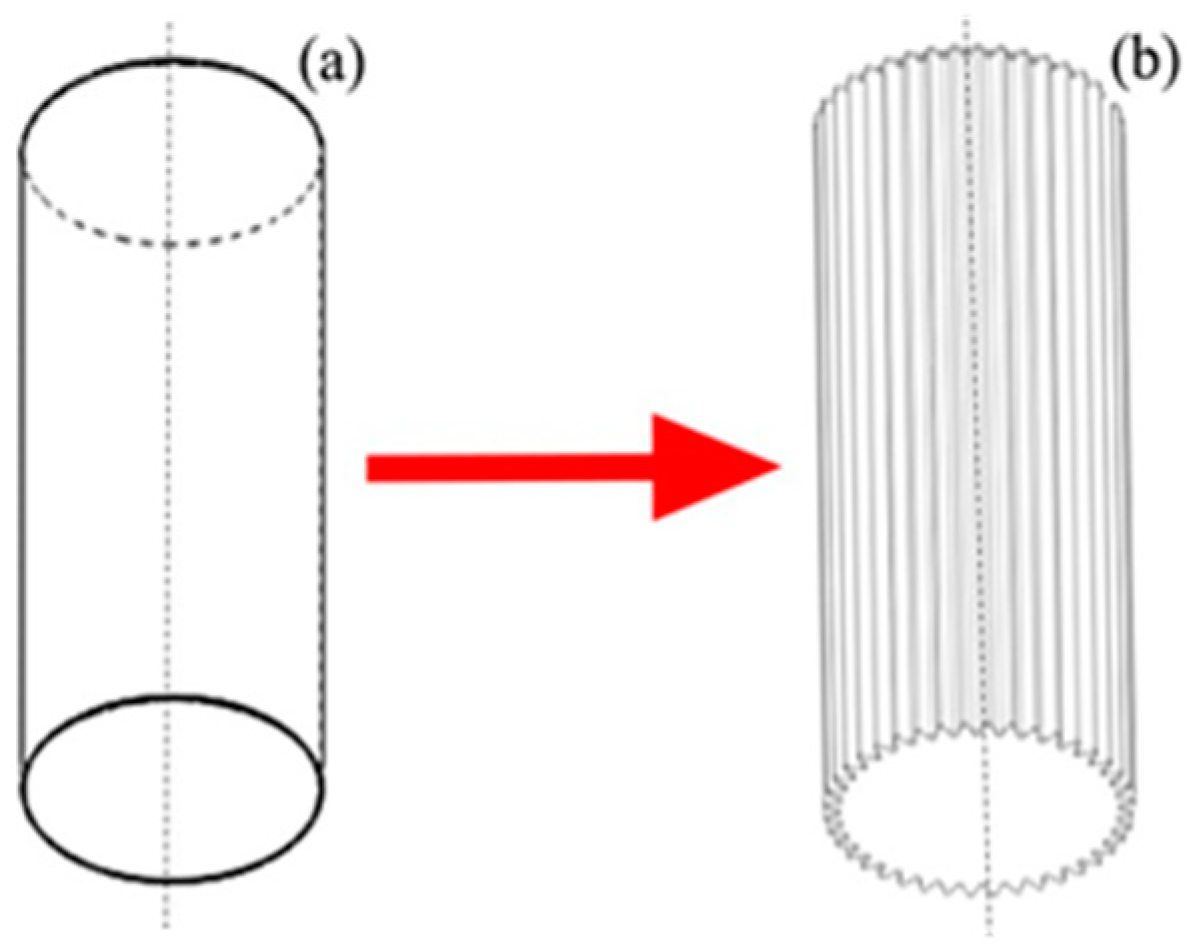
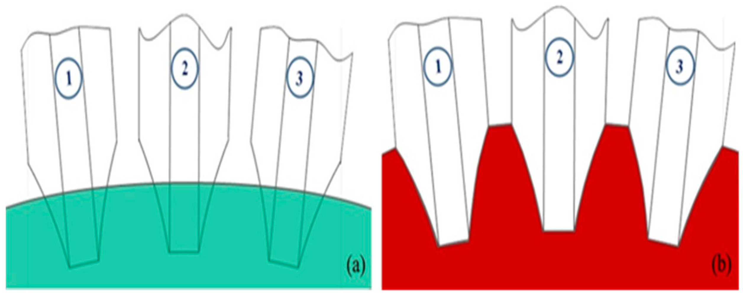
Starting from a cylindrical semi-finished product (see Figure 4a), the device manages to make toothed gears by hot forming, similar to that shown in Figure 4b.
In fact, the intermediate technical stages (viewed in cross section) are detailed in Figure 5.
4. Simulation
The simulations were performed by finite element analysis (FEA), using FORGE software.
4.1. The Dimension Assessment of the Initial Semi-Finished Product
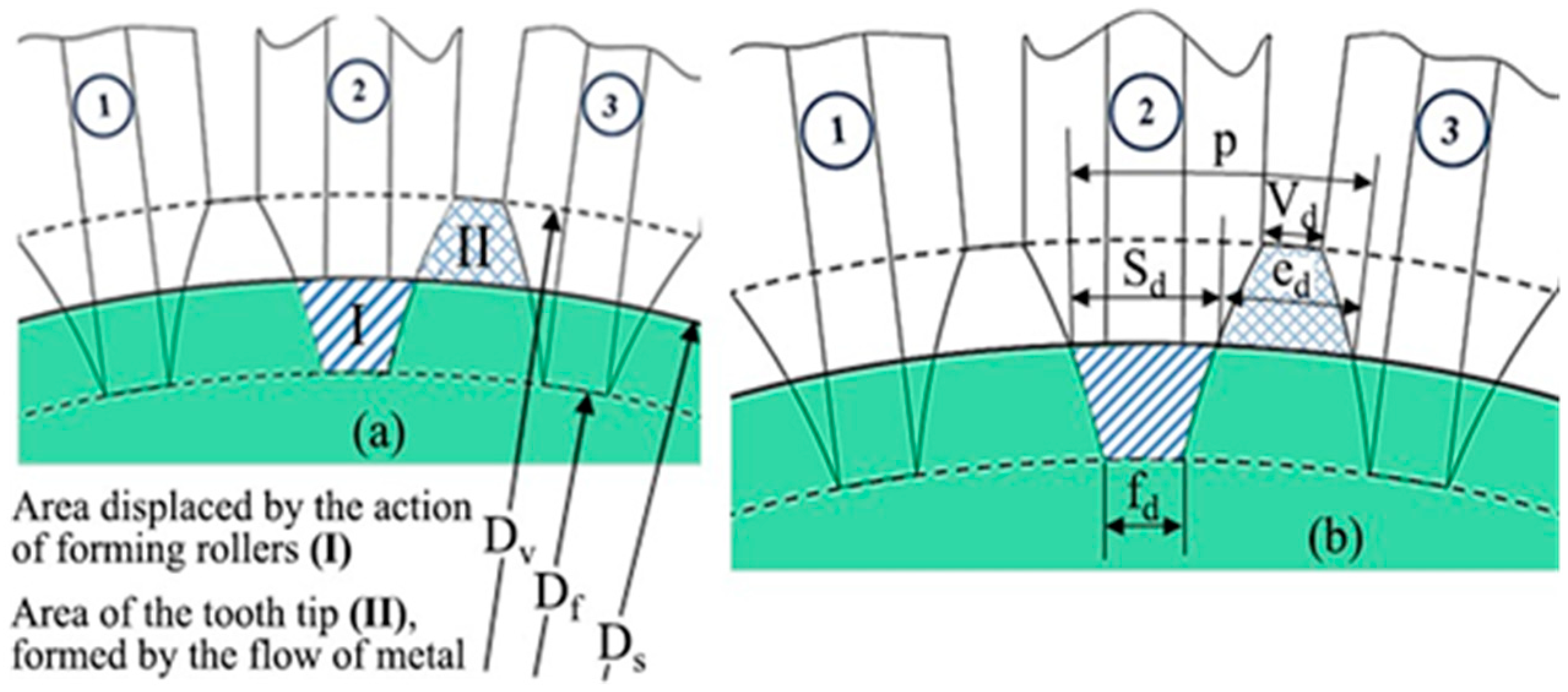
Basically, the diameter Ds of the semi-finished product and its height Hs were determined. The mathematical calculation of the diameter Ds of the semi-finished product implies that the sum of the transverse areas of the portions displaced by the action of the forming rollers must be equal to the sum of the transverse areas of the tooth tips formed by the flow of the material [4] (see Figure 6).
We estimated the area affected by the forming rollers, corresponding to the area displaced by their action (I) and the area of the tooth tip, formed by the flow of the material (II), respectively, with two trapezoids [5] whose surfaces are:
The approximation of and results in:
Ds = (Dv + Df)/2
- SI
- the area displaced by the action of the deforming rollers [mm2]
- SII
- the area of the tooth tip, formed by the flow of material [mm2]
- Ds
- the diameter of the initial semi-finished product [mm]
- Df
- the diameter of the dedendum circle [mm]
- Dv
- the diameter of the addendum circle [mm]
- sd
- tooth thickness [mm]
- ed
- tooth space [mm]
- p
- circular pitch [mm]
- fd
- tooth space peak thickness [mm]
- vd
- tooth peak thickness [mm]
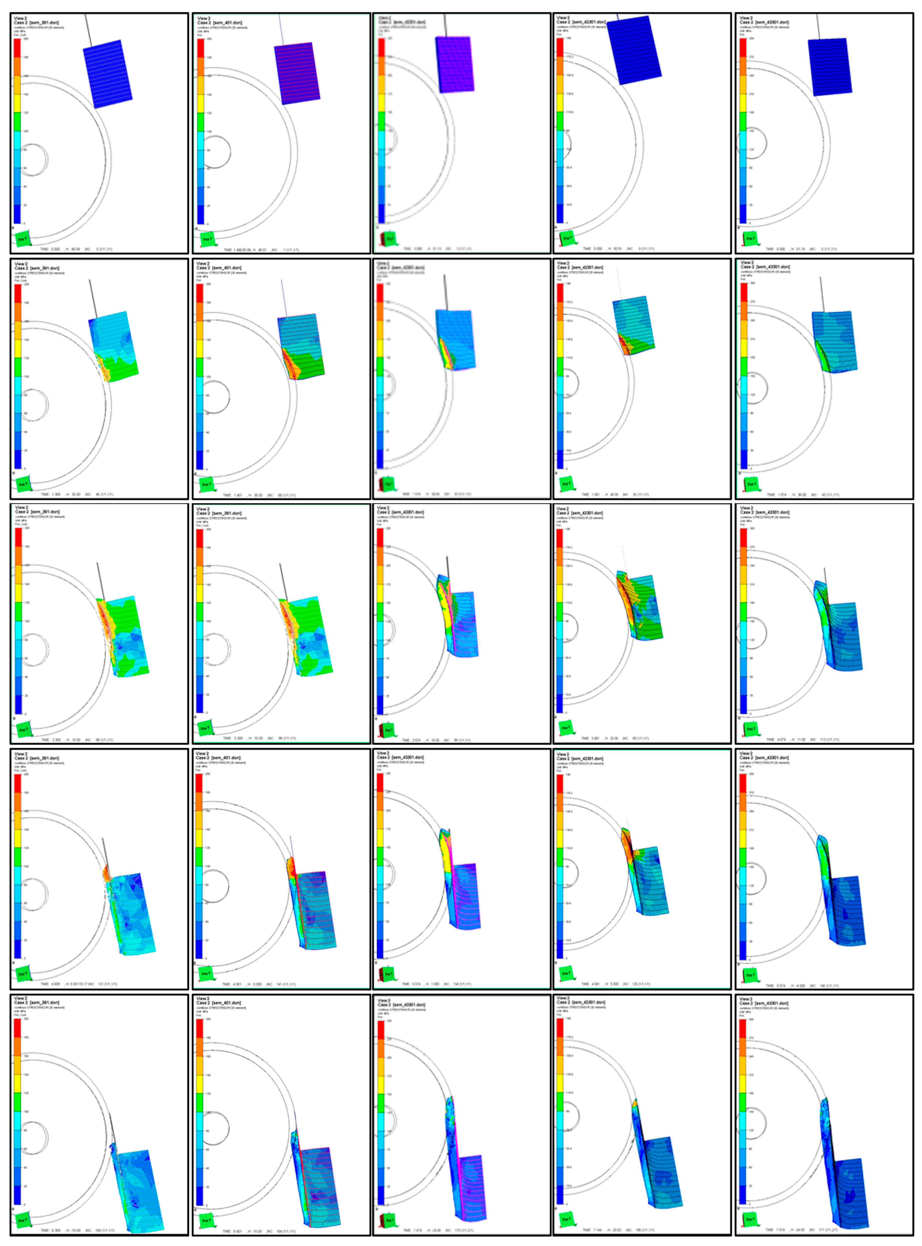
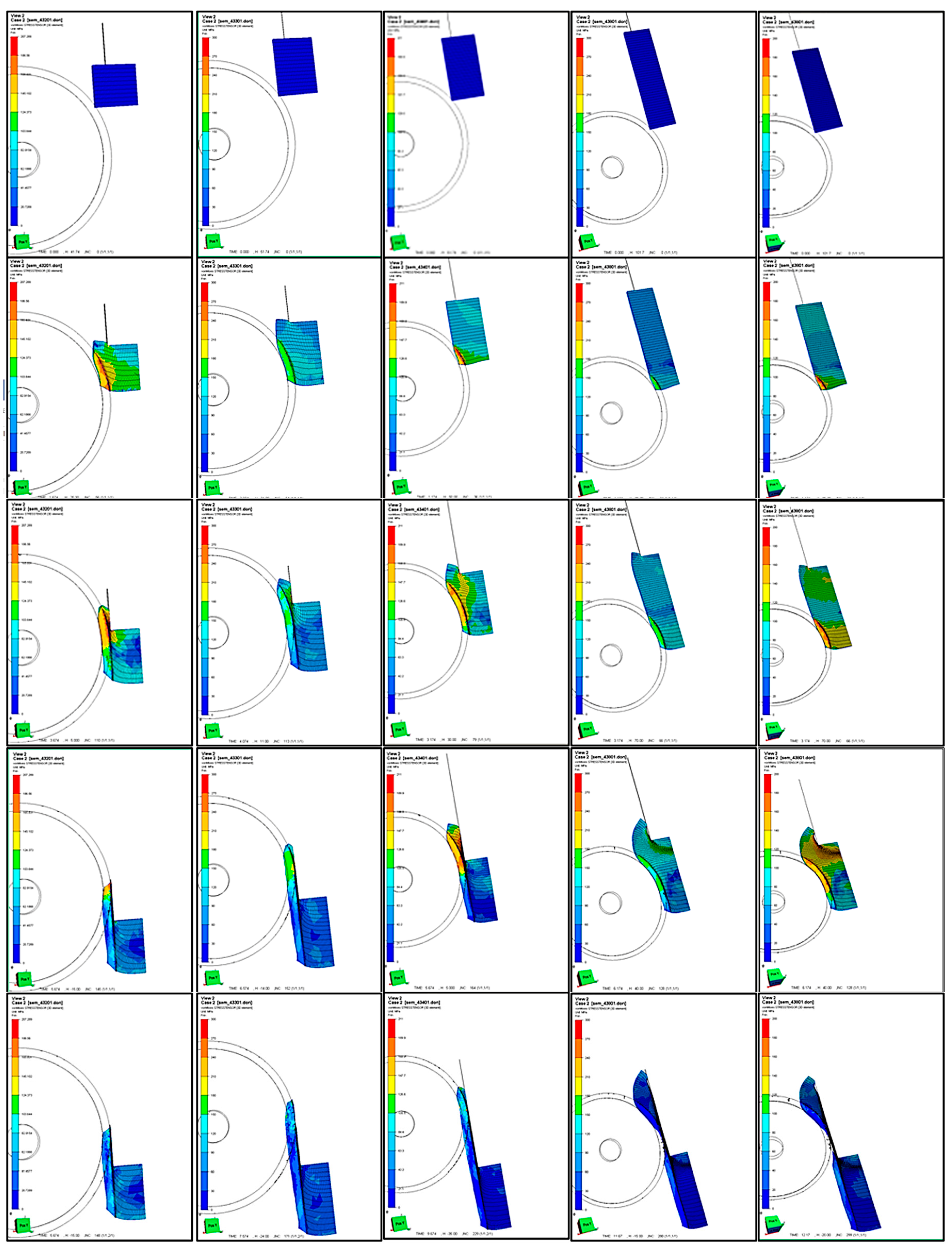
To correct the approximations from these calculations, FEA simulations were performed determining the von Mises stress and deducing the optimum dimensions of the initial semi-finished product: diameter, Ds (Figure 7), and height, Hs (Figure 8). The dimensions Ds and Hs are not specified as a value and are only relevant in correspondence with the dimensions of the device object of study. These dimensions were established so as to achieve the maximum degree of filling of the toothed gear by the flow of the material and a certain behavior in the process of its deformation.
4.2. The Von Mises Stress Determination
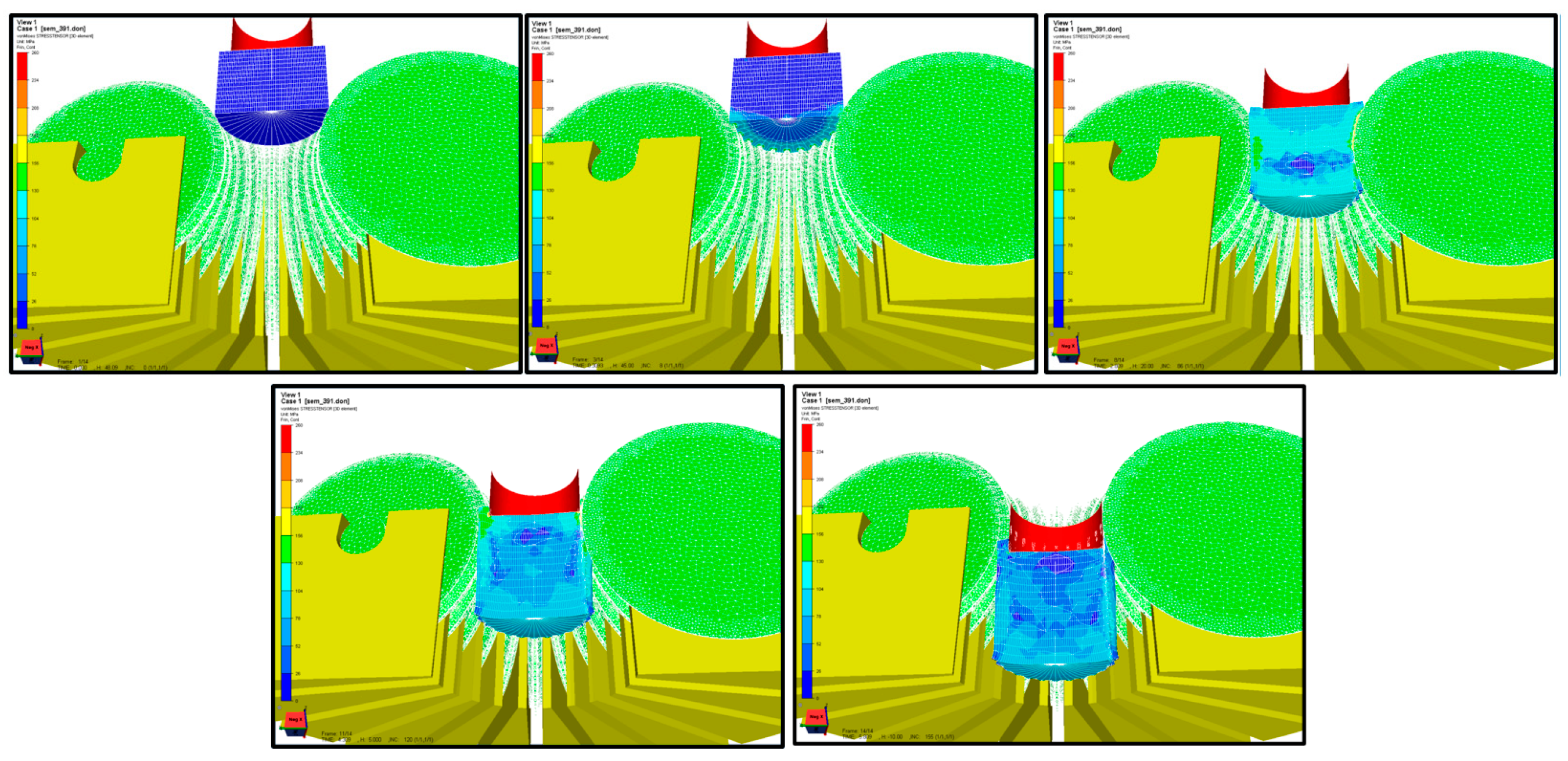
In the second phase, with these correct dimensions, a mesh network was applied both for the semi-finished product and for the analyzed device. Thus, the final values of von Mises stress were deduced. Because both the semi-finished product and the analyzed device were involved in the simulation at this moment, a view was achieved in its longitudinal section, focused on the von Mises stress that appeared at the deformation of the semi-finished product [6]. Figure 9 shows 5 figures made at various deformation moments: (a) corresponds to the deformation start time t = 0 (initial deformation moment), (b) corresponds to the moment t/5, (c) moment (2/5)·t, (d) moment (3/5)·t, (d) moment (4/5)·t and (e) the final moment (t = t).
4.3. The Semi-Finished Product Deformations
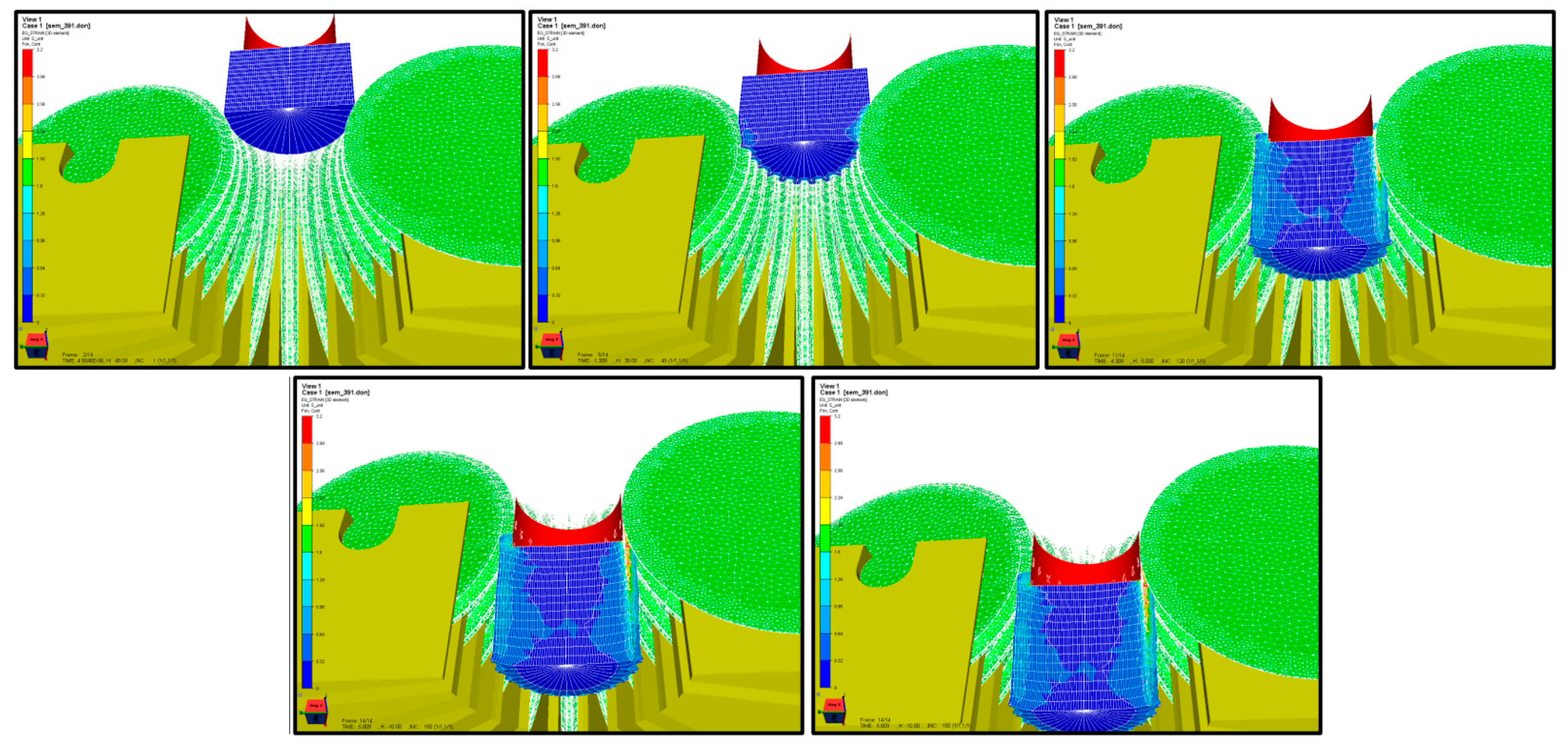
This simulation is similar as aspect to the previous one, practically focusing on the amplitude of the deformations of the semi-finished product along the entire time interval (t) of its deformation, as shown in Figure 10.
4.4. The Flow of the Semi-Finished Material
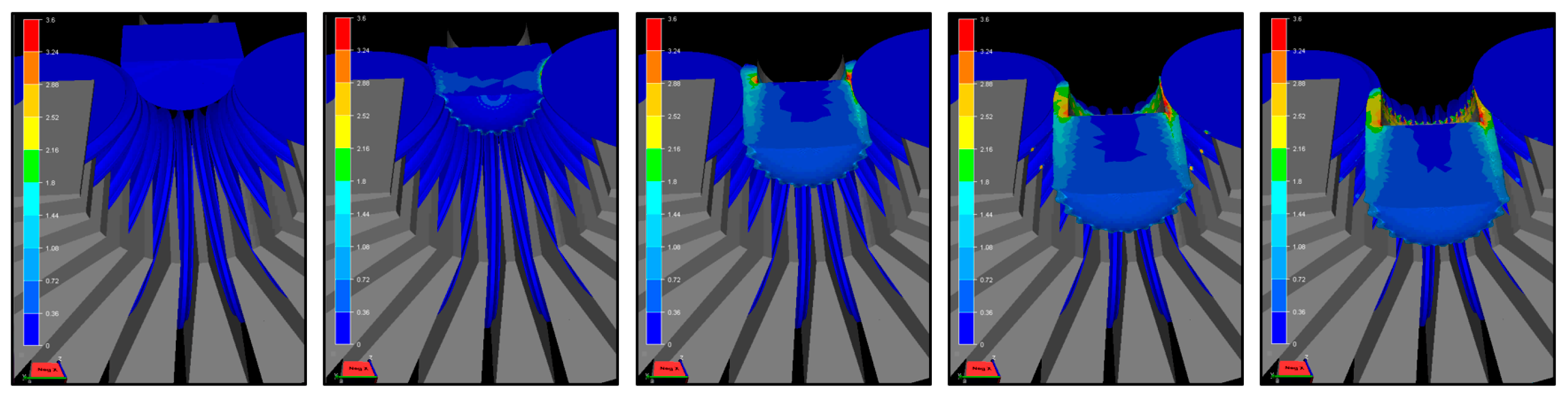
Mesh network was no longer viewed. The whole system device-part was cut from the entire longitudinal section with the aim of analyzing only the evolution of the flow of the part material, as shown in Figure 11.
5. Conclusions
In this research, it was proven that toothed gears with a certain circular pitch and number of teeth can be achieved by this method [7] of plastic deformation, and as with any process of plastic deformation, the fibrous structure being continuous, it results in a more resistant final product, able to respond more efficiently to various mechanical stresses [8]. During the practical hours of simulation, it was also observed that the flow of the material in the tooth formation imposes a certain regime of deformation speed. It was also observed that in the case of obtaining steel toothed gears, the respective deformation process will be performed hot, requiring only the heating of the cylindrical surface of the initial semi-finished product.
Funding
This research received no external funding.
Conflicts of Interest
The authors declare no conflict of interest.
References
- Pop, M. Plastic Deformations; Editura Mega: Cluj-Napoca, Romania, 2014; ISBN 978-606-543-509-4. [Google Scholar]
- Wright, N.R. Wire Technology. Process Engineering and Metallurgy; Elsevier: Amsterdam, The Netherlands, 2011; ISBN 978-0-12-382092-1. [Google Scholar]
- Rodriguez-Alabanda, O.; Guerrero-Vaca, G.; Romero, P. Machining time estimation using the geometrics features of the 2.5D pocket contour. Procedia Manuf. 2019, 41, 508–515. [Google Scholar] [CrossRef]
- Neugebauer, R.; Putz, M.; Hellfritzsch, U. Improved Process Design and Quality for Gear Manufacturing with Flat and Round Rolling. CIRP Ann. 2007, 56, 307–312. [Google Scholar] [CrossRef]
- André Weiß, A.; Liewald, M.; Weiß, A.; Missa, N. Manufacture of face gearing—A new production method by means of determined material pre-distribution. Procedia Manuf. 2018, 15, 511–518. [Google Scholar] [CrossRef]
- Armentania, E.; Mattera, A.; Sepe, R.; Esposito, L.; Naclerio, F.; Bocchini, G.F. Dies for pressing metal powders to form helical gears. Procedia Struct. Integr. 2018, 12, 457–470. [Google Scholar] [CrossRef]
- Linke, H.; Börner, J.; Heß, R. Manufacturing of Cylindrical Gearings. In Cylindrical Gears; Hanser: Munich, Germany, 2016; pp. 605–707. [Google Scholar] [CrossRef]
- ASM Handbook Volume 5: Surface Engineering; ASM International: Novelty, OH, USA, 1994; ISBN 978-0-87170-384-2.
Figure 1.
The principled sketch of the deformation mode with this device.

Figure 2.
The aspect of the “slice” subjected to simulation ((a)—longitudinal view, (b)—cross-sectional view, 1—the moving force, 1′—the direction of movement, 2—the semi-finished product, 3—the deforming rollers, 4—the body of device).
Figure 2.
The aspect of the “slice” subjected to simulation ((a)—longitudinal view, (b)—cross-sectional view, 1—the moving force, 1′—the direction of movement, 2—the semi-finished product, 3—the deforming rollers, 4—the body of device).

Figure 3.
The device for achieving of a toothed gear on presses: (a) the proposed version, (b) the built version; the forming rollers 3 and the body (fixed) of device 4. The notations are in correspondence with those from Figure 1.
Figure 3.
The device for achieving of a toothed gear on presses: (a) the proposed version, (b) the built version; the forming rollers 3 and the body (fixed) of device 4. The notations are in correspondence with those from Figure 1.

Figure 4.
The initial semi-finished product (a); the final product (b).

Figure 5.
Cross-sectional view of the processed semi-finished product: (a) the initial semi-finished product (green) and (b) the final product (red); the forming rollers are numbered as 1, 2, 3.
Figure 5.
Cross-sectional view of the processed semi-finished product: (a) the initial semi-finished product (green) and (b) the final product (red); the forming rollers are numbered as 1, 2, 3.

Figure 6.
(a) Main view of the semi-finished product deformation and (b) the previous view enlarged with the dimensions that appear in the nomenclature.
Figure 6.
(a) Main view of the semi-finished product deformation and (b) the previous view enlarged with the dimensions that appear in the nomenclature.

Figure 7.
The deduction of the diameter Ds of the initial semi-finished product by finite element analysis (FEA) simulation.
Figure 7.
The deduction of the diameter Ds of the initial semi-finished product by finite element analysis (FEA) simulation.

Figure 8.
The deduction of the height Hs of the initial semi-finished product by FEA simulation.

Figure 9.
The von Mises stress involved in the whole process of plastic deformation of the semi-finished product (the duration of the deformation was symbolized by “t”).
Figure 9.
The von Mises stress involved in the whole process of plastic deformation of the semi-finished product (the duration of the deformation was symbolized by “t”).

Figure 10.
The deformations involved in the whole process of plastic deformation of the semi-finished product.
Figure 10.
The deformations involved in the whole process of plastic deformation of the semi-finished product.

Figure 11.
The flow of the semi-finished material, in the process of its plastic deformation.

Publisher’s Note: MDPI stays neutral with regard to jurisdictional claims in published maps and institutional affiliations. |
© 2020 by the authors. Licensee MDPI, Basel, Switzerland. This article is an open access article distributed under the terms and conditions of the Creative Commons Attribution (CC BY) license (http://creativecommons.org/licenses/by/4.0/).
Share and Cite
MDPI and ACS Style
Tintelecan, M.; Iluțiu-Varvara, D.-A.; Rodriguez-Alabanda, O.; Sas-Boca, I.M.; Marian, I.; Gustavo, A.S.M. Achieving a Toothed Gear on Presses. Proceedings 2020, 63, 57. https://0-doi-org.brum.beds.ac.uk/10.3390/proceedings2020063057
AMA Style
Tintelecan M, Iluțiu-Varvara D-A, Rodriguez-Alabanda O, Sas-Boca IM, Marian I, Gustavo ASM. Achieving a Toothed Gear on Presses. Proceedings. 2020; 63(1):57. https://0-doi-org.brum.beds.ac.uk/10.3390/proceedings2020063057
Chicago/Turabian StyleTintelecan, Marius, Dana-Adriana Iluțiu-Varvara, Oscar Rodriguez-Alabanda, Ioana Monica Sas-Boca, Ionuț Marian, and Aristides Santana Martinez Gustavo. 2020. "Achieving a Toothed Gear on Presses" Proceedings 63, no. 1: 57. https://0-doi-org.brum.beds.ac.uk/10.3390/proceedings2020063057