
Design and Test of a Miniature Hydrogen Production Integrated Reactor


Department Applied Chemistry, University of the Basque Country (UPV/EHU), 20018 San Sebastian, Spain
*
Author to whom correspondence should be addressed.
Reactions 2021, 2(2), 78-93; https://0-doi-org.brum.beds.ac.uk/10.3390/reactions2020007
Submission received: 1 March 2021
/
Revised: 7 April 2021
/
Accepted: 12 April 2021
/
Published: 16 April 2021
(This article belongs to the Special Issue Hydrogen Production and Storage)
Abstract
:A detailed study of the experimental issues involved in the design and operation of a methanol steam microreformer is presented in this paper. Micromachining technology was utilized to fabricate a metallic microchannel block coupling the exothermic and endothermic process. The microchannel block was coated with a Pd/ZnO catalyst in the reforming channels and with Pd/Al2O3 in the combustion channels by washcoating. An experimental system had been designed and fine-tuned allowing estimation of the heat losses of the system and to compensate for them by means of electric heating cartridges. In this way, the heat necessary for the reforming reaction is provided by methanol combustion, thanks to the temperature and flow cascade controller we developed. Thus, the coupling of both reactions in a block of microchannels without the interference caused by significant heat loss due to the small size of the laboratory microreactor could be studied. Runs of this microreformer device were carried out, varying the deposited catalyst amount, methanol steam reforming temperature and space velocity. When the reforming reaction was compensated by the combustion reaction and the heat losses by the electric heating, an almost isothermal behavior of the microchannel reactor was observed. In the less favorable case, with a 460 mg catalyst load, ΔTMSR was about 8 K and ΔTCOMB was about 16 K. This confirmed good coupling of the methanol steam reforming and the methanol combustion.
1. Introduction
Hydrogen is a clean fuel that produces only water, electricity, and heat when it is consumed in a fuel cell. This fuel has the potential for use in a broad range of applications, across virtually all sectors—transportation, commercial, industrial, residential, and it is portable. Therefore, hydrogen and fuel cells can play an important role in decarbonization strategy for a sustainable energy future.
The production of hydrogen can be obtained by catalytic steam reforming of hydrocarbons such as methane, naphtha, methanol, ethanol, etc. [1]. Among the hydrocarbons considered in hydrogen production onboard, methanol has received much attention. The main advantage of methanol steam reforming (MSR) is the low reforming temperature (473–573 K) leading to a low carbon monoxide (CO) concentration in the product gases [1,2]. The MSR catalysts have to be efficient and highly selective toward CO2 over CO, which is important because the CO poisons the anode of the fuel cell [3].
In the reforming reactions, efficient heat transfer is important because MSR is a highly endothermic reaction (ΔH = 49.5 KJ/mol). Metallic microreactors, microstructured reactors with channels with a dimension below 1 mm, offer potential advantages of improved heat and mass transfer, more precise control of reaction temperature within flammable regions leading to reduced hot spots, and higher surface area to volume ratio of the microchannels [2,4]. Furthermore, these microdevices can be very compact and easily integrated with fuel stacks to generate power onboard. There are a large number of studies on the development of microreactors for hydrogen production [5,6,7].
Since MSR is an endothermic reaction, a heat source is necessary to maintain the reaction temperature. On an industrial scale, reforming reactors consist of a bundle of tubes that are externally heated by combustion. However, for more compact systems this solution is less viable because heat losses, integration and physical space become critical factors. Thanks to microreactors, a new way is opened to integrate the reforming and combustion reaction in the same reactor.
Microchannel reactors are gaining great importance due to the fact that they have great advantages such as an increase in the surface/volume ratio, a reduction in the reactor volume, an improvement in mass and heat transfer properties, and consequently a better control of the reactor temperature by reducing hot spots [8].
Regarding the heat losses, those produced by conduction through the tubes and connections of the microdevices can be important [9,10]. Although the size of the reactor can be remarkably reduced, pipes connecting the reactor to other components cannot be reduced in the same proportion. One way to minimize these heat losses is to achieve high levels of thermal integration and thus obtain high energy efficiencies. Sufficient energy must be supplied to the system to evaporate the feed mixture and maintain the desired temperature for the methanol reforming reaction [11,12,13,14,15]. The way of supplying the necessary heat to the reactor plays a very important role, an electrical supply being most used at the laboratory scale. In most cases, the reformer is heated externally by wrapping an electric heater around the reformer wall [2,16] or internally by placing a heat source inside the reformer [17].
However, the use of electrical power is not feasible on an industrial scale due to its high cost, so the combustion of a fuel is often used [18]. Thanks to the integration of an exothermic reaction in adjacent channels to those of the reforming, the efficiency of the system is improved and the design of the system is simplified. The thermal coupling becomes an important part of developing compact units for process intensification using microchannel reactors. Furthermore, the microreactor design and operating conditions have a great importance for optimal thermal management. It is therefore of great interest to determine the optimal conditions to provide design guidelines for hydrogen production using coupled combustion-reforming catalytic microreactors.
Among the possible fuels for the combustion reaction, one of the most interesting options is hydrogen from the rejection of the fuel cell. Fuel cells do not usually consume all the hydrogen fed from the reformer, normally around 20% leaves the fuel cell without being converted, its recovery being possible for feeding as fuel to provide the necessary energy in the reforming process. However, most microchannel reactor integration studies use the same methanol as fuel. Reuse et al. [19] were among the first to successfully combine both, the endothermic reforming reaction and the exothermic combustion of methanol. The improved isothermicity offers better performance as compared to other conventional reactors [20]. In our case, the fuel chosen is methanol, the same molecule that is being reformed, which facilitates the experimental device. This strategy, previously used by numerous authors [7,12,13,21], does not pretend to question the undeniable interest of using H2 from the cathodic rejection of the fuel cell as a more efficient alternative. However, in our opinion, the results of the integration of both reactions would be valid for the use of H2 as fuel.
The factors affecting the overall performance in the integration of catalytic combustion in a reformer can be summarized as follows: the material and thickness of the channel walls, the size of the channels, the geometry of the reactor, the heat losses, the type of fuel fed, the S/C ratio, the reactor length, and the type and amount of catalyst coating [21,22,23,24,25].
The influence of heat losses on the performance of the microreformers has rarely been addressed in the literature. Holladay et al. observed that for a small microreformer when the output is only 100 mWel the efficiency was 4.5% due to the strong influence of heat losses [10,26]. Shah and Besser studied the heat losses of a silicon microreactor for methanol reforming that produced 0.65 Wel [27,28]. The total energy requirement was 0.13 W (10% of the total) for the MSR, 0.20 W (15% of the total) for the vaporization of the reagents and 1.0 W to compensate for heat losses; that is, up to 75% of the energy consumed is lost in dissipations. According to these authors, the heat losses were due to natural convection, which was at least three times greater than the radiation losses. It should be noted that conduction heat losses through the tubes were not considered by these authors. Pan and Wang [5] performed a scale-up of a combustion-coupled reformer reactor. In the larger scale reactor, they found that heat losses were much lower than when working on a smaller scale and that less power was needed to heat the reforming chambers. Uriz et al. [9] observed by CFD simulation that under real operating conditions the energy demand can be up to nine times higher than just the reforming reaction due to heat losses.
Another factor to take into account is the relative architecture of the reforming and combustion flows [29]. There are several strategies to dispose of the flows of both reactions, the most common are parallel, opposite and crossed flow. From the point of view of isothermicity, the parallel flow is the most convenient and the opposite flow is the least suitable. However, when designing a microchannel block, cross-flow feeding offers the great advantage of facilitating the introduction of flows, simplifying the design of the system and the necessary connections.
In our previous work, we designed a methanol steam microreformer (8 cm3) which was able to produce 170 LH2/h, but the heat was supplied electrically [2]. In the present work, we manufactured a metallic microchannel block coupling the exothermic and endothermic process. The Pd/ZnO catalyst for MSR and Pd/Al2O3 for combustion were selected. The Pd/ZnO type catalysts exhibited comparable MSR activity to the Cu based ones (the most commonly used for MSR) with extremely low CO selectivity and higher thermal stability [30]. On the other hand, the most used catalysts for combustion are Pt, Pd or Rh noble metals dispersed on supports such as Al2O3, SiO2 or TiO2 [31]. The high activity of palladium and the high specific surface area of alumina help a better dispersion of the metal. In turn, the price of Pd is lower than that of Pt, which would lead to a cheaper industrial catalyst. Different experiments were carried out to evaluate the heat loss from the microchannel block, the endothermic heat requirement of the reforming reaction and the exothermic heat produced by the methanol combustion reaction. In this way, the total power requirement for continuous operation of the reformer has been estimated.
2. Materials and Methods
The metallic microchannel block was manufactured using iron base alloy (Fecralloy, Goodfellow, Wrexham, UK). The microchannels (depth: 700 μm; width: 700 μm; length: 20 mm; number of channels per plate: 10) were manufactured by micromilling on 20 mm × 20 mm × 1 mm plates. The machined plates were stacked, rotated 90° each one and were welded by diffusion welding using a nickel-based metallic glass interlayer with a composition of Ni–14B–7Si (wt.%, Goodfellow) [32]. This interlayer was an amorphous melt spun foil with a thickness of 25 μm. The bonding process was performed in vacuum using a test machine developed by Microtest at 850 °C with an applied force of 2.8 kN (∼7 MPa) for 40 min.
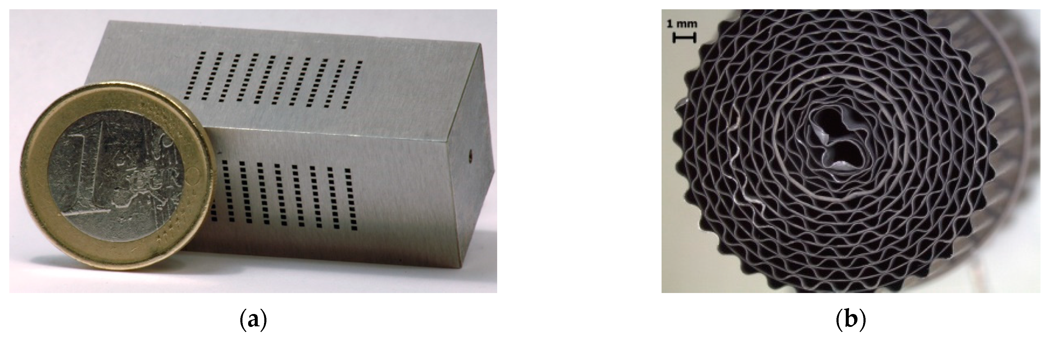
Final blocks designed to combine combustion and MSR were composed of 10 plates for MSR welded intercalated by 10 additional plates for combustion, resulting in 100 microchannels in each direction (see Figure 1). This architecture of crossed flows, despite not being the most efficient from the point of view of thermal integration [18], was the one that allowed a simpler flow connection (Figure 2c). Homemade parallel channel monoliths (L = 3 cm, diameter of 1.6 cm, 1100 cpsi) consisting of 50 μm Fecralloy sheets (Goodfellow) corrugated using rollers producing channel sizes similar to the microchannel block were manufactured (see Figure 1). These monoliths were used to optimize the washcoating variables used in the coating of the microchannel blocks and also to study the methanol combustion reaction. Monoliths were made by rolling alternate flat and corrugated sheets around a spindle. In order to improve the interaction between the catalyst coating and the metallic support, the microchannel blocks and monoliths were pretreated in air for 22 h at 1173 K generating a 5–6 μm thick and rough alumina layer.
The washcoating method was used to deposit both catalysts on the corresponding block microchannels. The catalyst slurries used were:
- Combustion catalyst slurry: first, Pd/Al2O3 catalyst was prepared via incipient wetness impregnation of Al2O3 (Spheralite) with the adequate amount of PdNO3 (Johnson Matthey) to obtain 0.25–1%Pd in the catalyst, dried and calcined at 773 K for 2 h. For this catalyst slurry preparation, a preliminary study, not shown here, on the variables that control the washcoating process was carried out [33]. The coating characteristics, specific load, homogeneity and adhesion were the control variables used to choose the best recipe (see Table 1).
- MSR catalyst slurry: first, ZnO was synthesized by thermal decomposition of Zn oxalate prepared by precipitation of ZnC2O4 from a 6 M nitrate solution by drop wise addition at 313 K of a 1.7 M oxalic acid solution [2]. For the catalyst slurry preparation, a new strategy developed in our previous work [34] was used, preparing the suspension in water with the catalyst precursors (see Table 1). In this way, the catalyst preparation and the substrate coating were carried out in a single step producing a much more active and stable structured catalyst showing excellent adherence to the substrate.
To allow the correct covering of only the walls of the corresponding microchannels, the pretreated microchannel blocks were previously covered with masking tape to protect the whole exterior surface except the entry and exit of the microchannels to be coated. The combustion catalyst was coated first as this requires double calcination which would further harm the MSR catalyst. The hanging blocks with the channels to be coated were oriented perpendicular to the surface of the slurry, dipped into the catalyst slurry for 60 s, and withdrawn at a constant speed of 3 cm·min−1. Then, the elimination of the slurry excess was made by blowing compressed air until all the channels were liquid free to prevent plugging [35]. The coating was repeated several times with an intermediate drying step at 393 K for 30 min between coatings until the desired combustion catalyst load was achieved (≈140 mg). Calcination of the coated block was done at 723 K for 2 h. After that, the blocks were dipped into the MSR catalyst slurry using the same withdrawing process, slurry excess elimination technique and drying steps until the desired MSR catalyst load (140, 245 and 417 mg) was obtained. Finally, the blocks were calcined at 623 K for 3 h.
The combustion reaction was also studied on microchannel monoliths. The monoliths were coated by the same method with combustion catalyst slurry (see Table 1) except that slurry excess elimination was made by centrifugation (1 min, 400 rpm). Finally, calcination of the coated microchannel monoliths was carried out at 723 K for 2 h.
The textural properties of the slurried catalyst were determined by nitrogen adsorption using a Micromeritics ASAP 2020. X-ray diffraction (XRD) analysis was performed on a Bruker D8 Advance Vårio. Diffraction patterns were recorded with Cu Kα radiation over a 0–60° 2θ using a position sensitive detector with a step size of 0.05° and a step time of 5 s. The adherence of the catalytic layer deposited was evaluated by the weight loss caused by the exposition of the sample to ultrasounds. The samples immersed in petroleum ether were submitted to an ultrasonic treatment for 30 min at room temperature. After that, the samples were dried and calcined. The weight loss was determined by the weight difference of the samples before and after the ultrasonic test. The results are presented as the percentage of the original coating remaining after the ultrasound treatment.
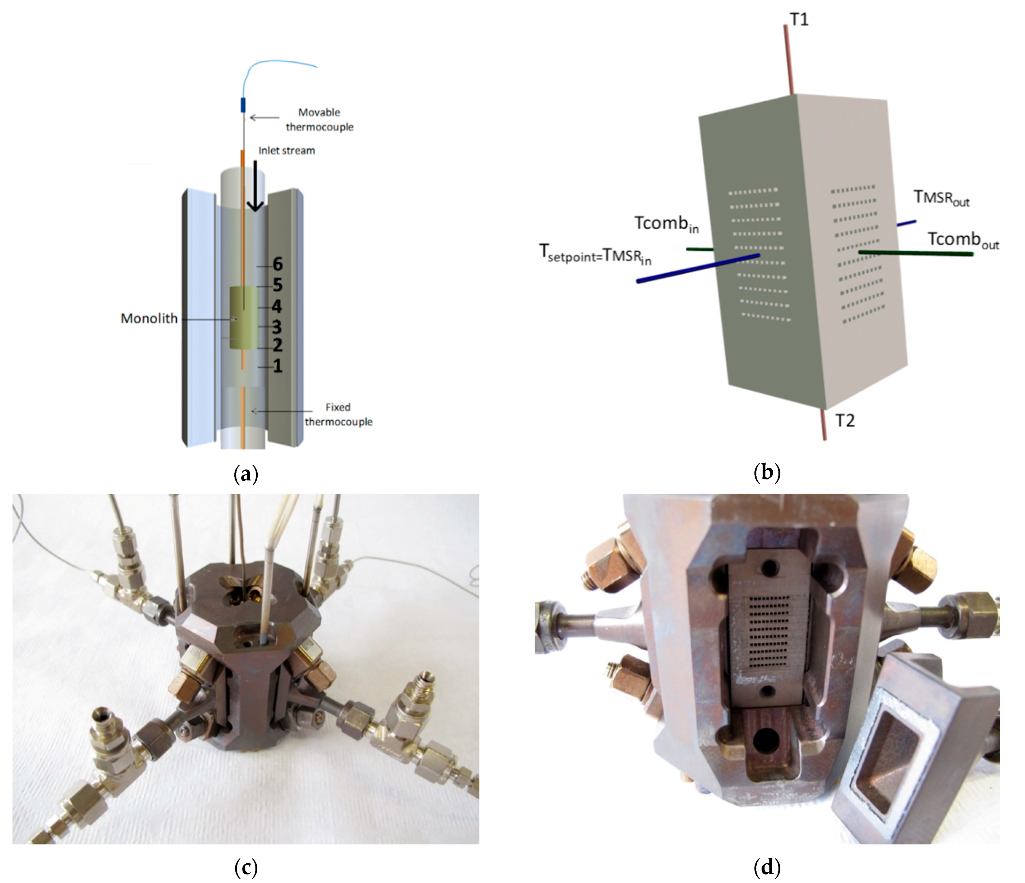
Catalytic tests of the microchannel block were carried out at atmospheric pressure using a Computerized Microactivity Reference Catalytic Reactor from PID Eng &Tech used as a mother reactor to house the reactor containing the microchannel block in its hot box. In this way, the mother reactor provides flow, pressure and temperature control systems, and connections for online analysis. The temperature of the microchannel block was monitored with 6 thermocouples (see Figure 2): 4 in the same horizontal plane, 2 of them at the microchannel entry and the other 2 at the microchannel outlet, and 2 additional thermocouples at the upper and bottom sides of the block. The thermocouple of the MSR inlet was used to set the temperature controller set point. The microchannel block was placed in the center of a housing (Figure 2b,c) that included the headers with their corresponding sealing gaskets that ensured the correct distribution of the inlet and outlet flow of the microchannels, the six thermocouples and four electrical cartridges. These cartridges allowed the reduction pretreatment to be carried out and could provide the necessary heat during the reaction acting alone or in combination with the methanol combustion reaction. Before introducing the casing with the block and all the accessories described in the hot box of the mother reactor, a thick layer of about 20 mm of thermal insulation made of mineral wool was added (Figure S1). For methanol combustion, methanol/air (5/95) was fed using a Bronkhorst CEM-System coupled to a cascade flow and temperature controller developed in collaboration with PI&D (flow rate was varied between 400–1600 NmL min−1). The main temperature controller acts on a slave methanol flow controller which in turn acts on another slave air flow controller which keeps the methanol/air ratio constant equal to 5/95. The methanol conversion was calculated by measuring the production of CO2 by an on-line IR detector (VAISALA).
Methanol combustion in the microchannel monolith was also performed in the hot box of the Microactivity apparatus (PID Eng & Tech) using a conventional 17 mm internal diameter tubular reactor and the same feeding and analysis lines indicated in the previous paragraph. The axial temperature profile was measured by fixing the oven power to ensure a temperature of 623 K in the center of the monolith and sliding the reading thermocouple from 1 cm before to 1 cm after the microchannel monolith (see Figure 2d).
For the methanol steam reforming, the catalyst was reduced at 773 K for 2 h, under a flow of 50 NmL min−1 of 10% H2 in N2. This reduction temperature was selected to ensure the formation of PdZn alloy, the active phase for MSR with low CO selectivity [36]. The reaction was carried out at 623 K with a steam-to-carbon molar ratio (S/C) of 1.5, using an HPLC (high-performance liquid chromatography) pump to feed the methanol-water mixture. Some 45% N2 was added to facilitate the evaporation of the methanol/water and to be used as the internal standard for GC. Gaseous products were taken out through a thermostatic line at 473 K and analyzed with a 7890A Agilent GC, using a TDC to analyze H2, CO, CO2, N2, H2O and CH3OH. Methanol conversion is defined as the ratio between converted methanol and the methanol fed,
CO and CO2 selectivity (Si) is defined as the ratio between produced CO or CO2 (ni) and the total carbon-containing species produced
,
3. Results
3.1. Microchannel Block and Monolith Preparation
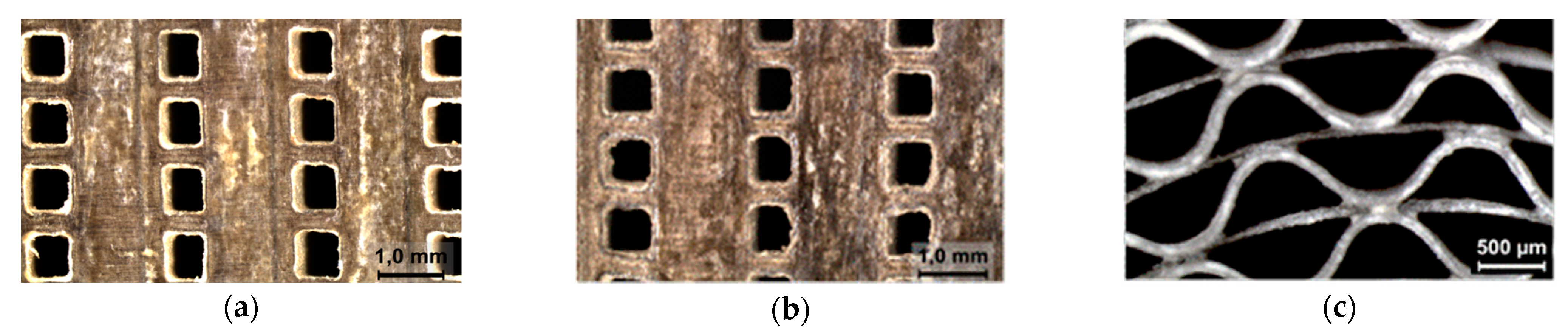
Microchannel coatings should be thin, which limits the methods that can be applied to coat structures. In all of these applications, an appropriate amount of catalytic material has to be distributed along the reactor channels. Therefore, the washcoating method was selected as the most favorable, due to its versatility that it is well suited to the geometry of our substrates, as we observed in our previous works [2,4,33]. A series of blocks and monoliths were prepared, and the washcoating method produced adherent (>90%) and homogeneous coatings without plugging the microchannels (see Figure 3).
Table 2 shows the textural properties of the powder catalysts obtained after drying and calcination of the slurry, called slurried catalysts. The Pd/ZnO catalyst presented a higher specific surface area than the parent ZnO due to a change in particle size during the preparation of the catalyst slurry for washcoating [36]. When the ZnO support was exposed to an acidic solution, some ZnO could have leached in the form of Zn2+ ions and reprecipitated onto the ZnO matrix, modifying the BET surface area. The Pd/Al2O3 catalyst presented a lower specific surface area than the commercial support due to the alumina colloid incorporated in the slurry formulation.
Figure 4 shows the wide-angle diffraction pattern of the synthesized catalyst. The XRD patterns of ZnO and Pd/ZnO showed peaks indexed by a hexagonal wurtzite phase of ZnO (JCPDS card no. 36-1451) and the high-temperature reduction led to 1:1 PdZn alloy formation at 41.5° (JCPDS no. 87-0639) [36]. The combustion catalyst showed characteristic reflections of Al2O3 at values 2θ = 19.4, 32.0, 37.7, 45.9 and 67.0 ° (PDF 79-1558) [37], and the reflections at 2θ = 33.8 and 54.7 ° (PDF 41-1107) were attributed to PdO [37]. The impregnation with Pd and the calcination did not modify the crystalline properties of the support.
3.2. MRS and Combustion Reaction in the Microchannel Block
The experiments carried out are indicated below, grouped by series with the reference assigned to them and which are indicated in the text (Table 3):
- Study of heat loss:
- ○
- For this study, the supplied electric power and temperature at different points were analyzed for the washcoated microchannel block at 623 K with different feed flows: 206 mL/min H2O/MeOH/N2, equivalent N2 flow and no flow throughout the reactor (HL-1).
- ○
- The influence of the reaction conditions on heat losses: temperature (HL-2), catalyst loading (HL-3), and reforming flow(HL-4).
- Study of combustion and reforming coupled on the block:
- ○
- In order to study whether the combustion reaction was carried out homogeneously along the microchannels, this reaction was previously studied on washcoated monoliths. The experiments were carried out modifying variables such as feed flow, catalyst load and Pd content of the catalyst, analyzing the combustion conversion and temperature profiles for each case (experiments not included in the table below).
- ○
- A series of experiments was carried out to evaluate in which conditions the dissipations were compensated with electrical power, and the reforming and decomposition reactions of methanol with the combustion reaction (CRC-1).
- ○
- Finally, in the next experiments, the heat losses were compensated with the electrical power, and the integration between the two reactions was studied varying the MSR reaction temperature (CRC-2), the MSR catalyst amount (CRC-3) and the space velocity (CRC-4).
3.2.1. Heat Loss on the Microchannel Block
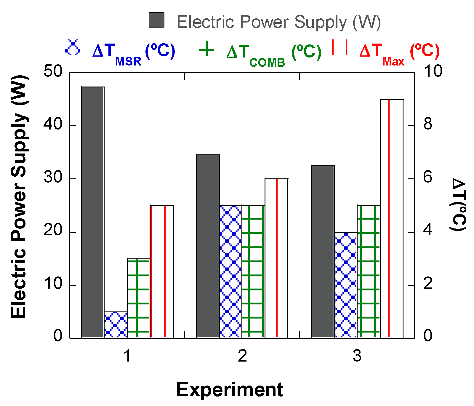
Figure 5 (experiments HL-1) shows the heat input to the integrated microchannel reactor during different operation conditions calculated as the electric power at a steady state required to stabilize the block at the chosen setpoint temperature, 623 K. In experiment 1, the microchannel block (245 mg of MSR catalyst and 140 mg of combustion catalyst) was electrically heated, maintaining the reaction temperature at 623 K using 15 mmolMeOH/min·gCat as feed. In these reaction conditions, the methanol steam reforming conversion of the reformer was about 98%, producing 60 LH2/h·gcat with very low CO selectivity (≈5%), and the consumed heat measured was 47.4 W. The energy required to compensate the endothermic reactions (QReact= 8.76 W) was quantified supposing that only the methanol reforming and methanol decomposition took place using PdZnO catalyst [38,39]. Comparing the results, it could be seen that the power provided to keep the reactor temperature at 623 K was much higher than that required for the methanol reforming reaction. The difference was due to the sensible heat necessary to heat up the feed and the heat dissipated to the hot box in which the reactor was located.
To differentiate between the heat dissipated by the microchannel reactor to the hot box and the sensible heat required to bring the feed at the reaction setpoint temperature, experiments replacing the reforming feed with nitrogen (experiment 2) and without feeding (experiment 3) were carried out (see Figure 5). Less power was required to maintain the microchannel block at the desired temperature when the reforming feed stream was replaced by nitrogen. The difference in power between the two experiments (≈8.34 W) matched reasonably the calculated reaction enthalpy. On the other hand, when the block was heated without any gas feed, it could be seen that the power to reach the temperature setpoint (623 K) decreased. Therefore, the sensible heat necessary to heat up the gas stream was 2.1 W at 623 K.
The smallest temperature difference in the block (ΔTmax) was obtained when a nitrogen flow was introduced (Figure 5), because the feed helped to homogenize the temperature in the block without heat consumption due to MSR reaction.
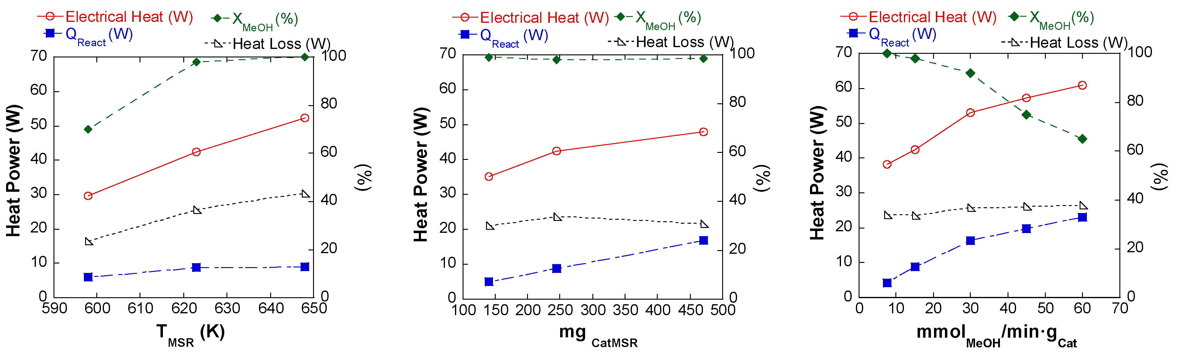
On the other hand, the influence of the reaction conditions (temperature (HL-2), catalyst loading (HL-3), and reforming flow (HL-4)) on the system was studied by heating electrically (Figure 6). At the scale studied here, the heat loss increased slightly with the steam reforming temperature (Figure 6a). At the studied conditions, increasing temperature from 598 to 648 K, the heat loss increased from 23.5 to 43.4 W. However, the heat losses changed slightly by increasing the catalyst loading and reforming fuel flow rate, being around 32 and 36 W, respectively (Figure 6b,c).
3.2.2. Combustion Coupled Block (Temperature Profile)
Methanol Combustion on Microchannel Monolith
First, the combustion reaction was studied on monoliths. These monoliths present channels of similar size to those of the microchannel block and allow the measurement of temperature along the microchannels direction. The experiments were carried out modifying variables such as feed flow, catalyst load and Pd content of the catalyst, analyzing the combustion conversion and temperature profiles for each case.
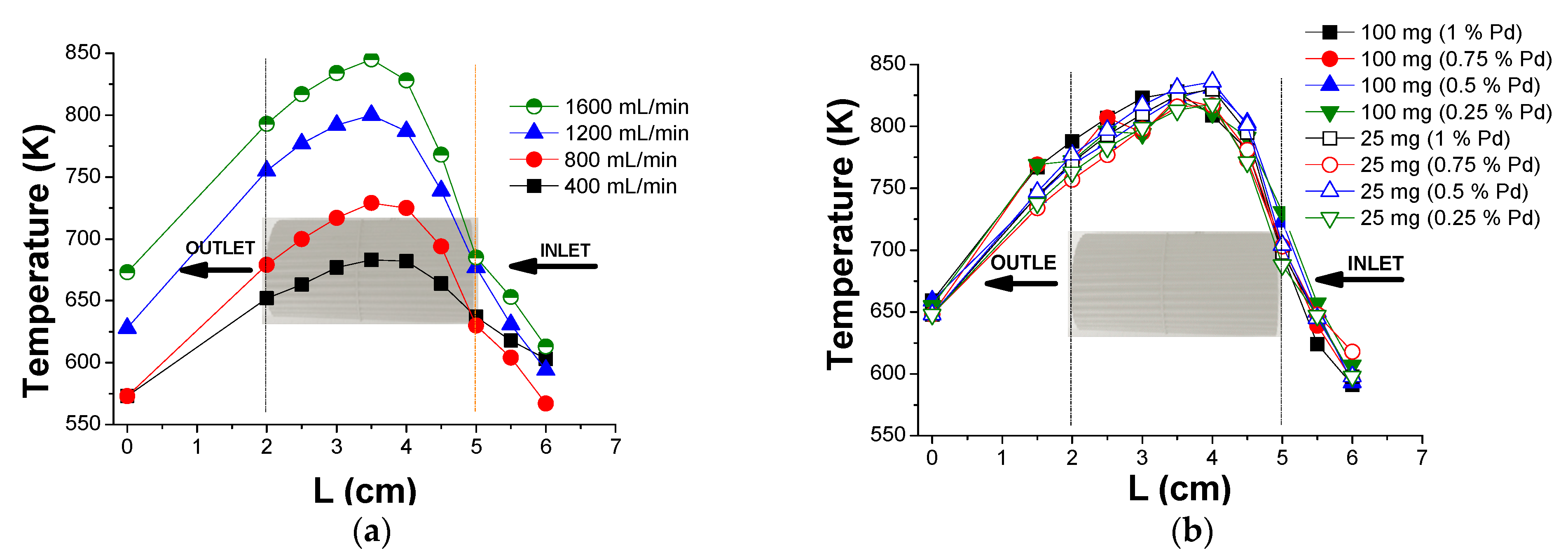
Figure 7 shows the temperature axial profile of the monolith coated with 200 mg of combustion catalyst at different feed rates. It can be observed that the temperature profile showed a similar shape in all cases, with a sharp temperature increase in the first centimeter, that is, combustion occurred at the entrance to the monolith. The only change when the feed flow increased, that is to say the amount of heat-generated increased, was that the temperature increase was greater. In all cases, 100% methanol conversion was achieved.
To see if this result was due to an active phase excess, several monoliths were coated with a lower catalyst amount and/or lower Pd content up to the limit that allowed us to guarantee a homogeneous distribution of the catalyst along the channel (Figure 7). The results showed that even decreasing to 25 mg of catalyst with 0.25% of Pd, it was not possible to smooth the temperature profile, obtaining similar curves and conversions of 100% in all cases. These results suggest that, at this initial temperature, the combustion catalyst has the only function of producing the ignition of the mixture that probably continues by a homogeneous mechanism.
Methanol Combustion on the Microchannel Block
The maximum temperature difference recorded between two points of the block (ΔTmax) was very small (≤5 K) when the system was heated only electrically (Figure 5). In subsequent experiments, the power of the cartridges was fixed at decreasing values (from 47 to 0 W) and the temperature (623 K) was controlled through the methanol combustion with the cascade flow and temperature controller (experiment CRC-1). As the electrical power was reduced, the combustion power required increased (increased methanol/air flow) producing an increase in combustion entry temperature (Figure 8). This increase could be due to the extremely fast combustion, as had been observed occurring at the microchannels’ entry (Figure 7). Nevertheless, the excellent heat conduction characteristics of the microchannel blocks and the consumption of part of the heat by the reforming reaction made the temperature differences (Figure 8) much smaller than those observed in the monolith (Figure 7).
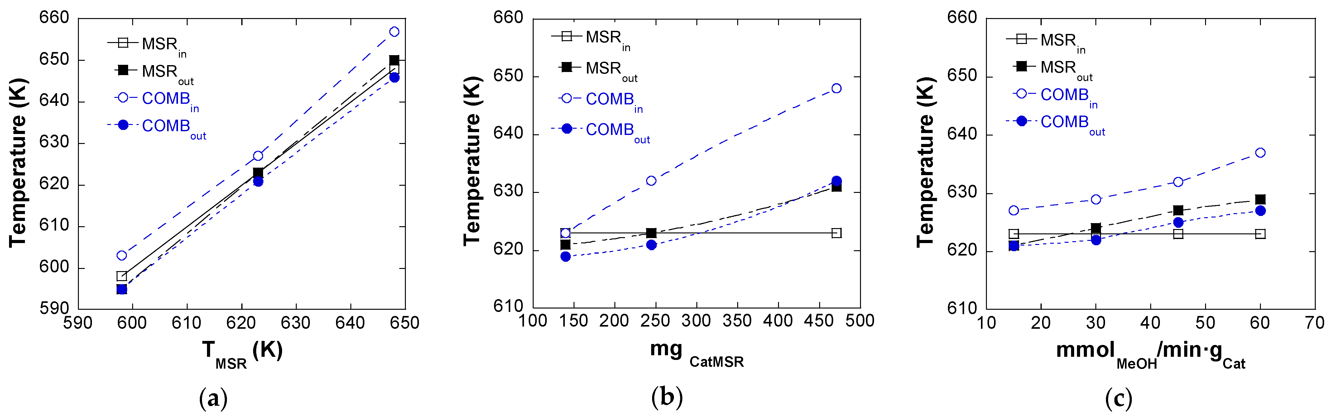
In the next experiments, the heat losses were compensated with the electrical power, and the integration between the two reactions was studied varying the MSR reaction temperature (CRC-2), the MSR catalyst amount (CRC-3) and the space velocity (CRC-4) (Figure 9). To carry out these experiments, the electrical power provided by the electrical cartridges to maintain the reactor at the desired temperature was first measured and the enthalpies of the reforming and decomposition reactions were calculated for the conversion obtained at each temperature. The difference between the total power and the reactions’ enthalpies would be the heat dissipated by the reactor. Therefore, in these experiments, a constant electrical power was provided for the heat losses and the rest of the heat necessary to reach the set-point temperature was provided by the methanol combustion.
Figure 9 compares the block temperatures at different reaction temperatures, catalyst loading and space velocity. For these studies, 120 mg of combustion catalyst and 150–460 mg of reforming catalyst were deposited in the microchannel block. It can be seen that the maximum temperature differences observed do not vary significantly in the range of temperatures studied (Figure 9a). On the other side, increasing the catalyst load (Figure 9b) and the space velocity (Figure 9c), the maximum temperature difference became larger. However, in the less favorable case, with 460 mg catalyst load, ΔTMSR was about 8 K and ΔTCOMB was about 16 K. Therefore, it can be said that a good isothermicity is obtained coupling methanol steam reforming and methanol combustion in the same microchannel block.
4. Discussion
With regard to heat losses, in this work it has been observed that the power required to compensate for the reforming reaction is only 15–20% of the total power needed to keep the block at the desired temperature. The rest of the power was required to compensate for heat losses (Figure 5). This value was very similar to that observed by other authors [10,26,27,28]. Uriz et al. [9] studied by CFD simulation the effect of heat losses in a methanol microreformer with the same design of the microchannel block and the catalyst used in the present work. They observed that the energy demand was up to nine times higher than just the reforming reaction due to heat losses. These heat loss problems are associated to the laboratory scale, as the outer surface/reaction volume ratio is very large. At an industrial scale, even when using microchannel reactors, this ratio would decrease dramatically, which together with the use of a more efficient insulating casing would lead to a decrease in the relative importance of heat losses with respect to the reaction heat.
In this work, we have designed and fine-tuned an experimental system that has allowed us to estimate the heat losses of the system and compensate for them by means of electric heating cartridges. In this way, the heat necessary for the reforming reaction is provided with the combustion of methanol thanks to a temperature and flow cascade controller. Thus, we can study the coupling of both reactions in a block of microchannels without the interference caused by the significant heat losses due to the small size of the laboratory microreactor.
Regarding the temperatures recorded in the microchannel block, it was observed that when the heat necessary for reforming and dissipations was provided solely by electrical power, the temperature difference in the block was small, around 5 °C (Figure 8). It could be said that the block worked in this case in an almost isothermal mode thanks to its high heat conduction. On the other hand, when supplying part of the heat through the methanol combustion reaction, the maximum temperature differences observed became higher (Figure 8). This was because the temperature at the entrance to the combustion side increased significantly: the exothermic combustion reaction occurred rapidly at the channels’ entry (Figure 7). As the combustion feed rate increased, the maximum difference in the block temperature increased and occurred at the combustion inlet, keeping the temperatures on the reforming side practically constant. The increase in the air/MeOH flow rate and the high activity of the combustion catalyst, caused an increase in the heat generated at the inlet of the block that was dissipated throughout the block (Figure 8). On the other hand, the lowest temperature was recorded at the combustion outlet due to the fact that most of the combustion occurred at the entrance of the channel and the reforming reaction and the heat losses absorbed part of the heat generated in the combustion decreasing thus said temperature.
Regarding the experiments when the reforming reaction was compensated by the combustion reaction and the heat losses by the electric heating, an almost isothermal behavior of the block of microchannels could be seen despite the small-scale problem (Figure 8 and Figure 9). Thanks to the high heat conduction that the microchannel blocks offered, it was possible to work in an almost isothermal mode, a behavior that has been also reported by several authors such as Lo et al. [40]. They recorded the temperatures in a reactor in which they coupled the methanol reforming reactions and methanol combustion. When the two reactions were operating, the different temperatures recorded throughout the reformer showed a variation of ±2 K. Won et al. [12] studied a reactor coated with Cu/ZnO/Al2O3 catalyst for reforming and Pt/ZrO2 for combustion. The microchannel inlets of the reagents for reforming and combustion were located in opposite positions, generating countercurrent flow. They obtained a temperature difference of ±6 K controlling the combustion temperature between 483–563 K. Kim [11] studied the methanol reforming reaction coupled to the combustion reaction at a reaction temperature of 523 K, achieving temperature differences between reforming and combustion of 4 K.
On the other hand, other authors have also observed an increase in the temperature differences due to the combustion reaction. The higher temperature at the combustion inlet could be due to the rapid combustion of methanol in the reactor inlet: this heat is consumed by the reforming reaction, and the rest by the heat losses in the system observing a lower temperature at the combustion outlet [12,41]. The presence of hot spots at the combustion inlet becomes more noticeable as the higher combustion feed flow is introduced [11,13], which can cause the catalyst deterioration and the reactor breakage [11].
The reforming reaction coupled to that of combustion in a microchannel reactor has also been studied by means of a CFD simulation in the work of Arzamendi et al. [29]. They observed that for a constant reforming space velocity the introduction of combustion flow increased the overall temperature in the reactor, causing a higher conversion of methanol. The temperature differences also depended on the integration design. Arzamendi et al. [29] studied different feed designs for reforming and combustion flows. They carried out a simulation in which they studied three ways of coupling the flows of both reactions: parallel, countercurrent and crossed. The advantage of using the cross flow compared to the others was the ease of the block piping connection system. They observed that for the same reaction conditions, parallel flow was the most convenient from the isothermicity point of view because they obtained a maximum temperature difference of 4 °C. However, with the countercurrent flow, the largest temperature difference in the block was obtained, reaching a difference of 19 °C and the arrangement used in our blocks, cross-flow, showed a temperature difference of 7 °C. Our experimental results (Figure 9) showed excellent agreement with the values predicted in the modeling work previously carried out by Arzamendi et al. [29]. In our less favorable case, with 460 mg catalyst load, ΔTMSR was about 8 K and ΔTCOMB was about 16 K. This confirms the good coupling of the methanol steam reforming and the methanol combustion.
5. Conclusions
A microchannel reformer/combustor was designed for methanol steam reforming. The obtained results show that:
- After the optimization of the washcoating process (slurry and procedure) excellent results of load, homogeneity and adhesion have been achieved on microchannel blocks. Successful and well-performing coatings of Pd/ZnO reforming catalyst and Pd/Al2O3 combustion catalyst were produced.
- An experimental system has been designed and fine-tuned allowing the heat losses of the system to be estimated and to compensate for them by means of electric heating cartridges. In this way, the heat necessary for the reforming reaction was provided with the methanol combustion thanks to a temperature and flow cascade controller developed. Thus, the coupling of both reactions in a block of microchannels without the interference caused by the significant heat losses due to the small size of the laboratory microreactor could be studied.
- The power provided to keep the reactor temperature was much higher than that required for the methanol reforming reaction and the sensible heat necessary to heat up the feed, due to the heat losses, dissipated to the hot box in which the reactor was located.
- The heat loss increased slightly with the steam reforming temperature, being relatively constant varying catalyst loading or reforming fuel flow rate.
- The methanol combustion is a very quick reaction and takes place near the microcombustor inlet. However, the microchannel reactor conductivity was able to maintain the methanol steam reforming reaction practically isothermal when coupling reforming and combustion reaction.
- When the reforming reaction was compensated by the combustion reaction and the heat losses by the electric heating, an isothermal behavior of the microchannels reactor was observed. In the less favorable case, ΔTMSR was about 8 K and ΔTCOMB was about 16 K, confirming the good coupling of both reactions.
Supplementary Materials
The following are available online at https://0-www-mdpi-com.brum.beds.ac.uk/article/10.3390/reactions2020007/s1, Figure S1: (a) Microreactor during insulation installation. (b) Microreactor with insulating shell, heater cartridges and six thermocouples. (c) Microreactor with the insulating shell and fluid connections installed in the hot box of the commercial mother reactor.
Author Contributions
Conceptualization, O.S. and M.M.; funding acquisition, O.S. and M.M.; investigation, I.V., I.P.-M. and O.S.; supervision, O.S. and I.L.; writing—original draft preparation, O.S. and M.M.; writing—review and editing, O.S. and M.M. All authors have read and agreed to the published version of the manuscript.
Funding
This research was funded by MICINN/FEDER grant numbers RTI2018-096294-B-C32 and CTQ2015-73901-JIN and by the Basque Government grant number IT1069-16.
Acknowledgments
I.P.-M. acknowledges the Basque Government for PhD scholarship (PRE_2014_1_141). The authors are thankful for the technical and human support provided by SGIker of UPV/EHU (X-ray diffraction measurements).
Conflicts of Interest
The authors declare no conflict of interest.
References
- Holladay, J.D.; Hu, J.; King, D.L.; Wang, Y. An overview of hydrogen production technologies. Catal. Today 2009, 139, 244–260. [Google Scholar] [CrossRef]
- Sanz, O.; Velasco, I.; Perez-Miqueo, I.; Poyato, R.; Odriozola, J.A.; Montes, M. Intensification of hydrogen production by methanol steam reforming. Int. J. Hydrog. Energy 2016, 41, 5250–5259. [Google Scholar] [CrossRef]
- Palo, D.R.; Dagle, R.A.; Holladay, J.D. Methanol steam reforming for hydrogen production. Chem. Rev. 2007, 107, 3992–4021. [Google Scholar] [CrossRef] [PubMed]
- Sanz, O.; Velasco, I.; Reyero, I.; Legorburu, I.; Arzamendi, G.L.; Gandía, M.; Montes, M. Effect of the thermal conductivity of metallic monoliths on methanol steam reforming. Catal. Today 2016, 273, 131–139. [Google Scholar] [CrossRef]
- Pan, L.; Wang, S. Methanol steam reforming in a compact plate-fin reformer for fuel-cell systems. Int. J. Hydrog. Energy 2005, 30, 973–979. [Google Scholar] [CrossRef]
- Yu, X.; Tu, S.-T.; Wang, Z.; Qi, Y. Development of a microchannel reactor concerning steam reforming of metanol. Chem. Eng. J. 2006, 116, 123–132. [Google Scholar] [CrossRef]
- Park, G.-G.; Seo, D.J.; Park, S.-H.; Yoon, Y.-G.; Kim, C.-S.; Yoon, W.-L. Development of microchannel methanol steam reformer. Chem. Eng. J. 2004, 101, 87–92. [Google Scholar] [CrossRef]
- Kolb, G.; Hessel, V. Micro-structured reactors for gas phase reactions. Chem. Eng. J. 2004, 98, 1–38. [Google Scholar] [CrossRef]
- Uriz, I.; Arzamendi, G.; Diéguez, P.M.; Echave, F.J.; Sanz, O.; Montes, M.; Gandía, L.M. CFD analysis of the effects of the flow distribution and heat losses on the steam reforming of methanol in catalytic (Pd/ZnO) microreactors. Chem. Eng. J. 2014, 238, 37–44. [Google Scholar] [CrossRef]
- Holladay, J.D.; Jones, E.O.; Phelps, M.; Hu, J. Microfuel processor for use in a miniature power supply. J. Power Sources 2002, 108, 21–27. [Google Scholar] [CrossRef]
- Kim, T. Micro methanol reformer combined with a catalytic combustor for a PEM fuel cell. Int. J. Hydrog. Energy 2009, 34, 6790–6798. [Google Scholar] [CrossRef]
- Won, J.Y.; Jun, H.K.; Jeon, M.K.; Woo, S.I. Performance of microchannel reactor combined with combustor for methanol steam reforming. Catal. Today 2006, 111, 158–163. [Google Scholar] [CrossRef]
- Chein, R.-Y.; Chen, Y.-C.; Chang, C.-M.; Chung, J.N. Experimental study on the performance of hydrogen production from miniature methanol–steam reformer integrated with Swiss-roll type combustor for PEMFC. Appl. Energy 2013, 105, 86–98. [Google Scholar] [CrossRef]
- Jin, J.; Kwon, S. Fabrication and performance test of catalytic micro-combustors as a heat source of methanol steam reformer. Int. J. Hydrog. Energy 2010, 35, 1803–1811. [Google Scholar] [CrossRef]
- Yoshida, K.; Tanaka, S.; Hiraki, H.; Esashi, M. A micro fuel reformer integrated with a combustor and a microchannel evaporator. J. Micromech. Microeng. 2006, 16, S191–S197. Available online: https://0-iopscience-iop-org.brum.beds.ac.uk/article/10.1088/0960-1317/16/9/S04 (accessed on 6 April 2021). [CrossRef]
- Cao, C.; Xia, G.; Holladay, J.; Jones, E.; Wang, Y. Kinetic studies of methanol steam reforming over Pd/ZnO catalyst using a microchannel reactor. Appl. Catal. A Gen. 2004, 262, 19–29. [Google Scholar] [CrossRef]
- Suh, J.-S.; Lee, M.-T.; Greif, R.; Grigoropoulos, C.P. Transport phenomena in a steam-methanol reforming microreactor with internal heating. Int. J. Hydrog. Energy 2009, 34, 314–322. [Google Scholar] [CrossRef]
- Chein, R.; Chen, Y.-C.; Chung, J.N. Axial heat conduction and heat supply effects on methanol-steam reforming performance in micro-scale reformers. Int. J. Heat Mass Transf. 2012, 550, 3029–3042. [Google Scholar] [CrossRef]
- Reuse, P.; Renken, A.; Haas-Santo, K.; Gorke, O.; Schubert, K. Hydrogen production for fuel cell application in an autothermal micro-channel reactor. Chem. Eng. J. 2004, 101, 133–141. [Google Scholar] [CrossRef] [Green Version]
- de Wild, P.J.; Verhaak, M.J.F.M. Catalytic production of hydrogen from methanol. Catal. Today 2000, 60, 3–10. [Google Scholar] [CrossRef]
- Tadbir, M.A.; Akbari, M.H. Methanol steam reforming in a planar wash coated microreactor integrated with a micro-combustor. Int. J. Hydrog. Energy 2011, 36, 12822–12832. [Google Scholar] [CrossRef]
- Stefanidis, G.D.; Vlachos, D.G. High vs. low temperature reforming for hydrogen production via microtechnology. Chem. Eng. Sci. 2009, 64, 4856–4865. [Google Scholar] [CrossRef]
- Chein, R.-Y.; Chen, Y.-C.; Chung, J.N. Thermal resistance effect on methanol-steam reforming performance in micro-scale reformers. Int. J. Hydrog. Energy 2012, 37, 250–262. [Google Scholar] [CrossRef]
- Stefanidis, G.D.; Vlachos, D.G. Intensification of steam reforming of natural gas: Choosing combustible fuel and reforming catalyst. Chem. Eng. Sci. 2010, 65, 398–404. [Google Scholar] [CrossRef]
- Chein, R.-Y.; Chen, Y.-C.; Lin, Y.-S.; Chung, J.N. Hydrogen production using integrated methanol-steam reforming reactor with various reformer designs for PEM fuel cells. Int. J. Energy Res. 2012, 36, 466–476. [Google Scholar] [CrossRef]
- Holladay, J.D.; Jones, E.O.; Dagle, R.A.; Xia, G.G.; Cao, C.; Wang, Y. High efficiency and low carbon monoxide micro-scale methanol processors. J. Power Sources 2004, 131, 69–72. [Google Scholar] [CrossRef]
- Shah, K.; Besser, R.S. Key issues in the microchemical systems-based methanol fuel processor: Energy density, thermal integration, and heat loss mechanisms. J. Power Sources 2007, 166, 177–193. [Google Scholar] [CrossRef]
- Shah, K.; Besser, R.S. Understanding thermal integration issues and heat loss pathways in a planar microscale fuel processor: Demonstration of an integrated silicon microreactor-based methanol steam reformer. Chem. Eng. J. 2008, 135, S46–S56. [Google Scholar] [CrossRef]
- Arzamendi, G.; Diéguez, P.M.; Montes, M.; Centeno, M.A.; Odriozola, J.A.; Gandía, L.M. Integration of methanol steam reforming and combustion in a microchannel reactor for H2 production: A CFD simulation study. Catal. Today 2009, 143, 25–31. [Google Scholar] [CrossRef]
- Sá, S.; Silva, H.; Brandão, L.; Sousa, J.M.; Mendes, A. Catalysts for methanol steam reforming—A review. Appl. Catal. B Environ. 2010, 99, 43–57. [Google Scholar] [CrossRef]
- Zwinkels, M.F.M.; Järås, S.G.; Menon, P.G.; Griffin, T.A. Catalytic materials for high-temperature combustion. Catal. Rev. 1993, 35, 319–358. [Google Scholar] [CrossRef]
- Cruz, S.; Sanz, O.; Poyato, R.; Laguna, O.H.; Echave, F.J.; Almeida, L.C.; Centeno, M.A.; Arzamendi, G.; Gandia, L.M.; Souza-Aguiar, E.F.; et al. Design and testing of a microchannel reactor for the PROX reaction. Chem. Eng. J. 2011, 167, 634–642. [Google Scholar] [CrossRef] [Green Version]
- Velasco-Ortiz, I. Catalizadores Estructurados y Reactores de Microcanales para el Reformado de Metanol. Ph.D. Thesis, University of the Basque Country, San Sebastian, Spain, 2015. [Google Scholar]
- Echave, F.J.; Sanz, O.; Montes, M. Washcoating of microchannel reactors with PdZnO catalyst for methanol steam reforming. Appl. Catal. A Gen. 2014, 474, 159–167. [Google Scholar] [CrossRef]
- Almeida, L.C.; Echave, F.J.; Sanz, O.; Centeno, M.A.; Arzamendi, G.; Gandía, L.M.; Sousa-Aguiar, E.F.; Odriozola, J.A.; Montes, M. Fischer–Tropsch synthesis in microchannels. Chem. Eng. J. 2011, 167, 536–544. [Google Scholar] [CrossRef]
- Echave, F.J.; Sanz, O.; Velasco, I.; Odriozola, J.A.; Montes, M. Effect of the alloy on micro-structured reactors for methanol steam reforming. Catal. Today 2013, 213, 145–154. [Google Scholar] [CrossRef]
- He, Z.; He, Z.; Wang, D.; Bo, Q.; Fan, T.; Jiang, Y. Mo-modified Pd/Al2O3 catalysts for benzene catalytic combustion. Int. J. Environ. Sci. 2014, 26, 1481–1487. [Google Scholar] [CrossRef]
- Mateos-Pedrero, C.; Silva, H.; Pacheco-Tanaka, D.A.; Liguori, S.; Iulianelli, A.; Basile, A.; Mendes, A. CuO/ZnO catalysts for methanol steam reforming: The role of the support polarity ratio and surface area. Appl. Catal. B Environ. 2015, 174–175, 67–76. [Google Scholar] [CrossRef] [Green Version]
- Dagle, R.A.; Platon, A.; Palo, D.R.; Datye, A.K.; Vohs, J.M.; Wang, Y. PdZnAl catalysts for the reactions of water-gas-shift, methanol steam reforming, and reverse-water-gas-shift. Appl. Catal. A Gen. 2008, 342, 63–68. [Google Scholar] [CrossRef] [Green Version]
- Lo, K.-F.; Wong, S.-C. A passively-fed methanol steam reformer with catalytic combustor heater. Int. J. Hydrog. Energy 2011, 36, 10719–10726. [Google Scholar] [CrossRef]
- Kwon, O.J.; Yoon, D.H.; Kim, J.J. Silicon-based miniaturized reformer with methanol catalytic burner. Chem. Eng. J. 2008, 140, 466–472. [Google Scholar] [CrossRef]
Figure 1.
Structured support images: (a) microchannel block; (b) microchannel monolith.

Figure 2.
Thermocouple arrangement: (a) for microchannel monolith (b) for microchannel block; (c,d) microchannel block housing including flow headers, thermocouples, and heating cartridges.
Figure 2.
Thermocouple arrangement: (a) for microchannel monolith (b) for microchannel block; (c,d) microchannel block housing including flow headers, thermocouples, and heating cartridges.

Figure 3.
Image of coated structured substrates: (a) MSR catalyst coating on microchannel block; (b) combustion catalyst coating on microchannel block; (c) combustion catalyst coating on microchannel monolith.
Figure 3.
Image of coated structured substrates: (a) MSR catalyst coating on microchannel block; (b) combustion catalyst coating on microchannel block; (c) combustion catalyst coating on microchannel monolith.

Figure 4.
XRD of the supports and catalyst.

Figure 5.
Power supply and temperature differences concerning the setpoint (623 K) in different experiments: reforming feed of 206 mL/min H2O/MeOH/N2 (1), equivalent N2 flow (2) or no flow throughout the reactor (3) (ΔTMSR = TMSRin − TMSRout, ΔTCOMB = TCOMBin − TCOMBout, ΔTMax = the maximum temperature difference observed between the 6 temperature points).

Figure 6.
Heat power and methanol conversion variations on microchannel block: (a) the effect of MSR temperature for 245 mg of MSR catalyst at 15 mmolMeOH/min·gCat; (b) the effect of MSR catalyst amount at 623 K and 15 mmolMeOH/min·gCat; (c) the effect of space velocity for 245 mg of MSR catalyst at 623 K.

Figure 7.
Temperature profile of monoliths: (a) different flows with monolith loaded with 200 mg and 1% Pd/Al2O3; (b) different monoliths with different catalyst loading and Pd content with the same feed flow 1600 mL/min.
Figure 7.
Temperature profile of monoliths: (a) different flows with monolith loaded with 200 mg and 1% Pd/Al2O3; (b) different monoliths with different catalyst loading and Pd content with the same feed flow 1600 mL/min.

Figure 8.
Temperature profile of the block as a function of the electrical power used at 623 K.

Figure 9.
Temperature profile of the block: (a) the effect of MSR temperature for 245 mg of MSR catalyst at 15 mmolMeOH/min·gCat; (b) the effect of MSR catalyst amount at 623 K and 15 mmolMeOH/min·gCat; (c) the effect of space velocity for 245 mg of MSR catalyst at 623 K.
Figure 9.
Temperature profile of the block: (a) the effect of MSR temperature for 245 mg of MSR catalyst at 15 mmolMeOH/min·gCat; (b) the effect of MSR catalyst amount at 623 K and 15 mmolMeOH/min·gCat; (c) the effect of space velocity for 245 mg of MSR catalyst at 623 K.


Table 1.
Catalyst slurry formulation.
| Compounds | MSR Catalyst Slurry (wt.%) | Combustion Catalyst Slurry (wt.%) |
|---|---|---|
| ZnO | 22.5 | - |
| PdNO3 (Johson Matthey) | 1.20 | - |
| Pd/Al2O3 | - | 16.0 |
| Colloidal Al2O3 (Nyacol AL20) | - | 2.00 |
| Colloidal ZnO (Nyacol DP5370) | 2.50 | - |
| Polyvinyl alcohol | - | 2.00 |
| H2O | 73.8 | 80.0 |
| pH | 4.3 | 4.1 |
Table 2.
Textural properties.
| Samples | SBET (m2/g) | Vpore (cm3/g) | Dpore (nm) |
|---|---|---|---|
| ZnO | 39 | 0.24 | 24 |
| Colloidal ZnO | 55 | 0.13 | 10 |
| 2.5%Pd/ZnO (slurried catalyst) | 50 | 0.25 | 19 |
| Al2O3 | 240 | 0.40 | 70 |
| Colloidal Al2O3 | 160 | - | - |
| 1%Pd/Al2O3 (slurried catalyst) | 234 | 0.41 | 68 |
Table 3.
The list of experiments carried out with microchannel blocks.
| Experiment Reference | Heating System | MSR Catalyst (mg) | Comb. Catalyst (mg) | TRefom. (K) | Space Velocity (mmolMeOH/min•gCat) | ||
|---|---|---|---|---|---|---|---|
| Electrical (%) | Comb. (%) | ||||||
| Heat loss | HL-1 | 100 | 0 | 245 | 140 | 623 | 15 |
| equivalent N2 flow | |||||||
| 0 | |||||||
| HL-2 | 100 | 0 | 245 | 140 | 598/623/648 | 15 | |
| HL-3 | 100 | 0 | 140/245/471 | 140 | 623 | 15 | |
| HL-4 | 100 | 0 | 245 | 140 | 623 | 7/15/30/45/60 | |
| Comb. Reform. Coupling | CRC-1 | 0 | 100 | 245 | 140 | 623 | 15 |
| 50 | 50 | ||||||
| 75 | 25 | ||||||
| 85 | 15 | ||||||
| 100 | 0 | ||||||
| CRC-2 | 15 | 85 | 245 | 140 | 598/623/648 | 15 | |
| CRC-3 | 15 | 85 | 140/245/471 | 140 | 623 | 15 | |
| CRC-4 | 15 | 85 | 245 | 140 | 623 | 7/15/30/45/60 | |
Publisher’s Note: MDPI stays neutral with regard to jurisdictional claims in published maps and institutional affiliations. |
© 2021 by the authors. Licensee MDPI, Basel, Switzerland. This article is an open access article distributed under the terms and conditions of the Creative Commons Attribution (CC BY) license (https://creativecommons.org/licenses/by/4.0/).
Share and Cite
MDPI and ACS Style
Velasco, I.; Sanz, O.; Pérez-Miqueo, I.; Legorburu, I.; Montes, M. Design and Test of a Miniature Hydrogen Production Integrated Reactor. Reactions 2021, 2, 78-93. https://0-doi-org.brum.beds.ac.uk/10.3390/reactions2020007
AMA Style
Velasco I, Sanz O, Pérez-Miqueo I, Legorburu I, Montes M. Design and Test of a Miniature Hydrogen Production Integrated Reactor. Reactions. 2021; 2(2):78-93. https://0-doi-org.brum.beds.ac.uk/10.3390/reactions2020007
Chicago/Turabian StyleVelasco, Ion, Oihane Sanz, Iñigo Pérez-Miqueo, Iñigo Legorburu, and Mario Montes. 2021. "Design and Test of a Miniature Hydrogen Production Integrated Reactor" Reactions 2, no. 2: 78-93. https://0-doi-org.brum.beds.ac.uk/10.3390/reactions2020007