
Fischer–Tropsch Synthesis for Light Olefins from Syngas: A Review of Catalyst Development


1
Catalysis and Chemical Reaction Engineering Laboratories, University of Saskatchewan, Saskatoon, SK S7N 5A9, Canada
2
Center for Applied Energy Research, University of Kentucky, 2540 Research Park Drive, Lexington, KY 40511, USA
*
Author to whom correspondence should be addressed.
Reactions 2021, 2(3), 227-257; https://0-doi-org.brum.beds.ac.uk/10.3390/reactions2030015
Submission received: 14 June 2021
/
Revised: 6 July 2021
/
Accepted: 16 July 2021
/
Published: 21 July 2021
(This article belongs to the Special Issue Catalytic Conversion of Carbonaceous Materials to Fuels and Chemicals)
Abstract
:Light olefins as one the most important building blocks in chemical industry can be produced via Fischer–Tropsch synthesis (FTS) from syngas. FT synthesis conducted at high temperature would lead to light paraffins, carbon dioxide, methane, and C5+ longer chain hydrocarbons. The present work focuses on providing a critical review on the light olefin production using Fischer–Tropsch synthesis. The effects of metals, promoters and supports as the most influential parameters on the catalytic performance of catalysts are discussed meticulously. Fe and Co as the main active metals in FT catalysts are investigated in terms of pore size, crystal size, and crystal phase for obtaining desirable light olefin selectivity. Larger pore size of Fe-based catalysts is suggested to increase olefin selectivity via suppressing 1-olefin readsorption and secondary reactions. Iron carbide as the most probable phase of Fe-based catalysts is proposed for light olefin generation via FTS. Smaller crystal size of Co active metal leads to higher olefin selectivity. Hexagonal close-packed (HCP) structure of Co has higher FTS activity than face-centered cubic (FCC) structure. Transition from Co to Co3C is mainly proposed for formation of light olefins over Co-based catalysts. Moreover, various catalysts’ deactivation routes are reviewed. Additionally, techno-economic assessment of FTS plants in terms of different costs including capital expenditure and minimum fuel selling price are presented based on the most recent literature. Finally, the potential for global environmental impacts associated with FTS plants including atmospheric and toxicological impacts is considered via lifecycle assessment (LCA).
1. Introduction
Olefins including ethylene, propylene, and butylene are considered the most widely used petrochemical feedstocks used as chemical intermediates for production of solvents, polymers, plastics, fibers, and detergents. The demand for ethylene as one of the important derivatives of olefins is over 155 million tons annually. The common method for olefin production is steam cracking (SC) of hydrocarbons. The trend of ethylene production using thermal cracking had a growth rate of 4% between 2007 and 2012 [1]. The ethylene production in Canada is based on ethane as a feed through steam cracking at high temperatures. From 2000 to 2010, it was reported that the propylene production declined while the ethylene production increased [2].
Heavy petroleum oil with low API gravity containing different impurities such as sulfur, nitrogen, and metals brings about many challenges during its processing to the light olefins. Petroleum oil is estimated as the main energy source up to 2040 based on the OPEC’s World Oil Outlook in 2016, with the energy demand reaching to 382 million barrels of oil equivalent per day (mboe/d). As olefin production depends on oil fractions and steam cracking, the increasing demand for light olefins can cause strain on crude oil resources [3]. The non-oil routes for olefin production can be categorized in four groups, namely methanol to olefin (MTO), ethanol to olefin (ETO), dimethyl ether to olefin (DMTO), and the Fischer–Tropsch synthesis (FTS), which was developed in 1922 [4].
The technologies including MTO and FTS use methane as a feedstock for higher hydrocarbon production in an indirect way, while oxidative coupling of methane (OCM) is a direct route for ethylene and higher hydrocarbons production using methane. The H2/CO ratio in CO-rich syngas needs to be adjusted by water–gas shift (WGS) reactions to eliminate the CO level, while resulting in CO2 emissions [2]. However, the adjustment of H2/CO ratio is not necessary for the H2-rich syngas. Synthesis of an intermediate like methanol or dimethyl ether is the basis of MTO and dimethyl ether-to-olefin (DMTO) processes to produce light olefins indirectly, while Fischer–Tropsch to olefins process is based on a one-step reaction consuming synthesis gas without adjustment of H2/CO ratio [2]. An MTO plant is shown in Figure 1 where methanol is consumed in an MTO reactor and light olefins are separated within two stages of separation.
Coal, natural gas, and biomass are the main source of synthesis gas for olefins production. Coal and biomass are converted to syngas via gasification, while the conversion of natural gas to syngas is carried out through steam reforming. The established FTS plants presented in Table 1 show a tendency toward natural gas compared to coal over the years [6]. FTS provides two advantages compared to MTO. The lower cost of olefin production in FTS involves a one-step process. Additionally, a wide range of raw materials can be used as feedstocks in FTS, with less wastewater production throughout the process [7]. Oil resource depletion and high cost of exploration has led scientists to develop alternative feedstocks for the olefins production. Biomass and waste streams including solid plastic waste or municipal waste are good candidates for future use in olefins production, indicating that FTS can be regarded as an environmentally friendly and economical process for light olefins production [8].
So far only iron and cobalt catalysts have been proven economically feasible on an industrial scale for FTS. However, iron possessing high water–gas-shift (WGS) activity compared to cobalt, can be an ideal catalyst for FTS. Selectivity is the most important challenge in the FTS process. In this process, the catalyst activity and selectivity are influenced by nature and structure of support, nature of metal, reactive sites, metal dispersion, metal loading, and catalyst preparation method [10]. Moreover, addition of promoting agents to catalysts significantly increases the activity and selectivity of catalysts toward a specific range of products, e.g., light olefins. Therefore, to optimize the selectivity of FTS to light olefins, conditions favoring high olefin to paraffin ratio should be achieved.
2. Catalysts for Fischer–Tropsch to Olefins (FTO)
Generally, the catalyst selectivity is based upon four factors including bond strength, coordination, ensemble, and template properties. The principle of bond strength is the electronic characteristics of the atoms involved. The number of possible reactions in the FTS is influenced by bond strength varying from no chemisorption for weak bond to slow desorption for strong bond [11]. Catalyst basicity, dispersion, active metals, and promoters as well as support interaction can influence the selectivity of FTS toward light olefins. Ponec et al. [12] linked the olefins selectivity to electronic and geometric factors. Moreover, Biloen et al. [13] asserted that whenever a molecule contacts the catalyst surface, the reactants react due to the chemistry and geometry of the catalyst’s active sites.
2.1. Catalyst Active Metal E-ffects
Transition metals capable of syngas (H2 + CO) adsorption and reducibility of metal oxides are used as FTS catalysts. Transition metals belonging to groups III-VI of the periodic table have tendency to form highly stable oxides that are difficult to be reduced in FTS, while they can be used for dissociative adsorption of CO. Additionally, some transition metals including Cu, Pd, Pt, and Ir have difficulty with CO dissociation resulting in high methanol selectivity in FTS. It is suggested that Fe, Co, Ni, and Ru are suitable transition metals for FTS, due to high rates of CO dissociation and subsequently high rate of chain growth [14]. In some research, Rh was found to be suitable [15]. However, it has been reported that Ru is not an economical catalyst due to its limited resources and high price. Nickel is observed to be selective to methane rather than the desired products. Therefore, Fe and Co are the most common metals for FTS catalyst [16]. Fe-based catalysts are more likely to tolerate sulfur impurities than Co, thus suggesting for biomass and coal derived syngas. Moreover, Fe possesses a lower hydrogenation activity compared to Co, as a result, Fe provides higher selectivity toward olefins [17]. Interestingly, there is a growing attention to molybdenum carbide as catalyst for catalytic reactions due to high activity for CO hydrogenation and dry reforming as well as its resistance to carbon deposition in comparison with Co- and Fe-based Fischer–Tropsch catalysts [18].
2.1.1. Iron-Based Catalysts
Iron catalysts at lower temperatures are selective to paraffins, while by increasing temperature the selectivity changes toward olefins. Due to similarity of CO hydrogenation and iron carbide formation in terms of activation energy, the iron carbides are formed during the FTS process. Different format of iron carbides have been observed in FTS process [19]. Table 2 shows a summary of iron-based catalysts for light olefin production via FTS. The nature and concentration of the promoters play a pivotal role in FTO catalysts and their selectivity. Galvis et al. [20] studied the addition of sulfur plus sodium in low concentration to Fe/α-Al2O3 catalyst with high C2-C4 olefins selectivity to improve the catalytic activity and decrease the methane production. Sodium addition caused a decrease in the methane selectivity due to the chain growth probability, while sulfur addition led to a higher olefin production [20].
Various iron-based FTS catalysts along with catalyst synthesis methods and active phases is listed in Table 2. The most probable compounds in Fe-based catalysts are iron carbide, metallic Fe, and magnetite (Fe3O4). Identification of active phase in Fe catalyst is commonly performed by in situ magnetization measurement to obtain curie temperature in which the first derivative of magnetization altering with temperature is plotted. Then, the active phase of catalysts will be identified based on the observed curie temperature. Iron carbide can be in the form of ε-Fe2C, ε’-Fe2.2C, Hägg χ-Fe5C2, Fe7C3, or θ-Fe3C. Active phases of Fe-based catalysts in FTS to light olefins have been mostly reported to be iron carbides in the form of Hägg χ-Fe5C2, ε-Fe2C, ε’-Fe2.2C, and Fe7C3. Carbides of ε-phase are stable below 250 °C, while Hägg carbide is stable in the range of 250–350 °C. Therefore, among iron carbides, χ-Fe5C2 is mostly known as active phase of typical FTS temperature (240–360 °C), with curie temperature between 205 °C and 238 °C [21]. Fe7C3 is a carbide phase produced during CO-treatment of catalyst at moderate temperature and θ-Fe3C is stable above 350 °C [22].
Chang et al. [22] investigated pretreatment of Fe/SiO2 catalysts with CO, H2, and syngas for FTO in the medium temperature range of nearly 260–300 °C and 20–30 bar for H2/CO = 2. They identified Fe7C3 and χ-Fe5C2 as active phases for CO-treated catalyst, while they reported ε-Fe2C and χ-Fe5C2 as active phase composition in H2-treatment. χ-Fe5C2 was the only carbide formed during syngas-treatment of Fe/SiO2 catalyst. Among these three carbide phases, the highest activity and the lowest methane selectivity belong to Fe7C3 and ε-Fe2C for medium range of temperature in FTO.
Jiang et al. [31] performed a series of experiments on Fe-based catalysts to control the catalytic activity, selectivity and deactivation in FTS process using different supports (γ-Al2O3, SiO2, activated carbon (AC), anatase-TiO2 and SiC) and promoters (K, Na, and S). It was concluded that the catalytic activity depends on the iron oxide reducibility which is related to the particle size-dependent carburization, promoter effects, interaction of iron with the support, and the particle size. The light olefin selectivity is increased beyond the limitation of the Schulz–Flory distribution using K, Na, and S. Finally, the reversible transformation of χ-Fe5C2 into Fe3O4 and K-induced carbon deposition were highlighted as the catalyst deactivation reasons [31]. Li et al. [30] synthesized K-promoted graphite supported catalysts during two stages including co-precipitation and incipient wetness impregnation. The FTS process was performed at 0.5 MPa and 300–330 °C using syngas (H2/CO = 1) for 4 h. The potassium-promoted catalyst showed high activity and selectivity of liquid hydrocarbon. Subsequently, the iron electron density increased while methane production went down [30]. Wang et al. [43] investigated an iron-catalyzed FTS process and promoter effects on light olefin selectivity. They reported Hägg iron carbide (χ-Fe5C2) as the dominant phase of iron catalyst used in Fischer–Tropsch reaction. It can be observed from Figure 2 that there are three different synthesis methods for pure χ-Fe5C2 catalyst including wet-chemical method, hydrothermal synthesis followed by thermal treatment method, and metal organic framework (MOF) mediated synthesis method. It was concluded that χ-Fe5C2 catalysts favor the synthesis of longer-chain hydrocarbons and alkanes. Moreover, the selectivity to C2-C4 can be improved using appropriate promoters [43]. Feyzi et al. [36] utilized Fe-Ni/Al2O3 catalyst for production of light olefins using synthesis gas. They reported that the catalyst offers the highest selectivity toward C2-C4 olefins (77.8%) and the lowest selectivity with respect to methane (9.1%) and CO2 (0.3%) at 340 °C, H2/CO = 2, P = 1 bar. Moreover, addition of K2S into the catalyst increases the selectivity toward C2-C4 [36].
Olefin selectivity is not affected by Fe particle size; however, it is reported that Fe nanoparticles less than 7–9 nm exhibit higher CH4 selectivity compared to larger particles. Moreover, the smaller Fe nanoparticles lead to the lower chain growth probability. It was suggested that CH4 formation is related to the corners and edge sites of catalyst crystals, which is enhanced by decreasing the particle size. In the case of olefins, the terrace sites are proposed to improve olefin production [44]. The larger pore size of the support increases heavy hydrocarbon production and light olefin selectivity. It was reported that Fe-based catalysts (FeMn) with pore size in the order of 50–80 nm facilitated the diffusion of reactants and products while suppressing the secondary reactions of 1-olefins, thus resulted in higher selectivity toward light olefins [32].
2.1.2. Cobalt-Based Catalysts
Cobalt-based catalysts for FTS have properties such as high catalytic activity, low WGS activity, and superior stability. Therefore, this group of catalysts require higher ratios of H2/CO (2.0–2.2) compared to Fe-based catalyst [45]. However, these types of catalysts are not selective to the light olefins for industrial application. The electron density and structure of cobalt catalysts are mainly influenced by metal–support interactions. The support acidity could lead to light hydrocarbons formation. The support porosity including average pore diameter, pore volume, and surface area could affect the cobalt dispersion and reducibility. Noble metals, transition metal oxides, and some rare earth metal oxides are suggested as promoters for the cobalt oxide catalyst. In addition, the promoter affects the structure and dispersion of cobalt species, FT reaction rates, and product selectivity [46]. Table 3 shows some of support materials and promoters used for synthesis of Co-based catalysts using different synthesis methods.
Concerning the decrease of long chain hydrocarbons (C25+), Sage and co-workers [49] investigated the in-situ pre-treatment of Co/Ru/La catalysts using alumina support with acetylene pre-treatment (200 °C, 10 bar, 4 h) in a fixed-bed reactor. It was suggested that the formation of carbidic and CxHy species onto the catalysts can be related to acetylene dissociation and dehydrogenation. Methane TPH-MS revealed that acetylene decomposition causes formation of carbidic compounds. These carbidic compounds bring about a decrease in catalyst activity due to polymeric carbon onto the catalyst surface. Moreover, formation of these carbonaceous materials onto catalyst active sites was considered to alter the distribution of FTS products through affecting the 1-olefin secondary reactions. It was observed that the amount of heavy hydrocarbons significantly decreased [49].
Zhou et al. [55] evaluated the effects of 1,4-Butanediol (BDO) as a solvent using Co/MnOx catalyst in the FTO reaction. It was observed that BDO as a solvent affected the light olefin selectivity (42.2%) compared to the conventional Co/MnOx catalyst (26.5%). The main effect of BDO could be weakening the interaction of cobalt and support so that the cobalt density of the surface increases and the hydrogenation activity reduces. Co/MnOx-BDO catalysts weaken the isomerization and hydrogenation reaction, thus forming more light olefins. This catalyst also decreases the methane selectivity, while doubling olefin/paraffin ratio [55]. Pedersen et al. [50] succeeded to synthesize CoMn/γ-Al2O3 for light olefins production. Manganese enhanced the activity and selectivity to light olefins and C5+ species. In addition, the selectivity to CH4 decreased compared to the un-promoted Co catalyst. Mn was suggested to change the degree of reduction of Co3O4 particles together with a decrease in the cobalt surface area. Adding Mn to Co catalyst would lead to higher temperature peak in temperature programmed reduction (TPR) profiles and delayed reduction of Co3O4. Mn also inhibited hydrogenation activity due to the decrease in CH3 and CH4 formation [50].
Ryu et al. [48] used Ru-, Pt- and La-promoted Co-Al2O3/ZSM-5 hybrid catalysts for the direct production of gasoline (C5-C9) from syngas. Based upon NH3-TPD, promoter addition affects the surface acidity of the catalyst and product distribution. The catalytic activity of the promoted Co-Al2O3/ZSM 5 catalyst was evaluated at 240 °C, 2 MPa and H2/CO = 2 for 40 h in FTS process. Among catalysts, the Co-Al2O3-Pt/ZSM 5 showed the highest conversion of 41.3% while the olefin selectivity was just 17.9%, which was related to the presence of fewer acidic sites [48].
Liu et al. [65] investigated the mechanisms of CO activation, methane formation, and C–C coupling on three cobalt phases (Co, Co2C, Co3C) to find active site which affects the light olefins production in cobalt-catalyzed FTS reactions. It was found that the phase change from metallic Co into Co3C increases the selectivity to light olefins, although Co2C exhibits much lower activity and high selectivity to methane formation. The computational study was applied to indicate the active sites that affect the olefin production. It was believed that the reactions conducted at the Co/Co3C interface is related to the formation and desorption of light olefins [66]. It is also discussed that Co catalyst deactivation is related to the carbide formation and carbon deposition [67]. Xing et al. [47] used hierarchical HZSM-5 and conventional HZSM-5 zeolite supports for cobalt catalysts in FTS to evaluate the selectivity of the process. Changing the support pore size was found to influence the selectivity of products like isoparaffin, olefin, and hydrocarbon clearly [47].
According to the literature for Co2C particle smaller than 7 nm, increasing the cobalt carbide particle size enhanced the intrinsic activity and light olefin selectivity [68]. Bulk Co known as hexagonal close-packed (HCP) structure was the dominant phase for particle size larger than 40 nm; however, the metastable Co of face-centered cubic (FCC) structure was limited to particles smaller than 20 nm. Thermal phase transformation of HCP to FCC was observed at 400 °C. It was suggested that Co-based catalysts of HCP crystal phase are more likely to have higher FTS activity compared to FCC structure [44]. Zhang et al. [69] suggested CHO-insertion and carbide mechanism for the initial formation and growth of carbon chain over FCC and HCP Co facets. As it can be seen in Figure 3, initial formation of CH2 is contributed to CO direct dissociation and hydrogenation on HCP Co, while in the case of FCC Co, CO hydrogen-assisted dissociation initiates formation of intermediates [69]. It was also reported that the carbide mechanism on Co preferably suggested higher selectivity of C2 hydrocarbons compared to CH4 [70].
2.2. Catalysts’ Basicity Effects
The basicity effects impact the strength required for the hydrogenation of syngas on the transition metals such as Mn, Fe, Co, and Ni. The basicity and reducibility of catalysts can be evaluated by characterization techniques including CO2-temperature programmed desorption (CO2-TPD) and H2-temperature programmed reduction (H2-TPR), respectively. Table 4 illustrates the effects of nature of supports and active metals on the catalyst basicity, with CO2-desoprtion temperature being increased for strong basic sites.
As can be seen in Table 4, the type and amount of alkali metal can influence phase transition in catalyst reduction, which is evaluated by H2-temperature programmed reduction.
Xiong et al. [74] investigated the effects of alkali metal promoters such as Li, Na, and K on the catalytic performances of iron catalyst supported on carbon nanotubes in FTS in the absence of strong metal support. Results demonstrated that addition of alkali metal influenced the catalyst crystallite size, with the surface area being decreased. The basicity of the alkali metal increases in the order Li < Na < K. It was also reported that an increase in Na and K loading increased the olefin/paraffin ratio and long-chain hydrocarbon formation [74]. In another study, addition of alkali to the Fe/SiO2 catalysts resulted in some changes in the reduction of catalyst due to strong interactions between alkali and iron metal. Potassium would lead to inhibition of first reduction of iron oxide. However, it enhanced the metallic iron formation from FeO and activity of iron catalysts in FTS. Moreover, by increasing the alkali atomic number, the carbonization of catalysts enhanced [72]. Li et al. [75] studied the effects of alkali metals as promoters on iron based FTS catalysts. They showed that Li and Na can penetrate to the catalyst surface. However, K, Rb, and Cs generally are not able to diffuse into the catalyst. By using alkali, the selectivity toward olefin and heavier hydrocarbons enhanced, while the selectivity toward methane and alkane decreased at the same time. It is confirmed that Li diffused out of the catalyst; however, K is less movable in iron catalyst after FTS reactions. The main effect of alkalis was attributed to the surface adsorption, with CO adsorption and dissociation being improved [75]. MgO as both basic support and structural promoter in Fe-based catalyst can increase olefin to paraffin ratio by suppressing secondary hydrogenation reaction. Fe-based catalysts in the form of MgO nanosheet and MgO cube were prepared by incipient wetness impregnation, deposition–precipitation, and ultrasonic impregnation methods. It was reported that Fe/MgO nanosheet catalysts synthesized using ultrasonic impregnation method exhibited the strong basicity sites of MgO (Table 4). The as-mentioned catalyst enhanced dissociative adsorption of CO and demonstrated higher olefin selectivity of 29.6% compared to the other catalysts [37]. CO2-temperature programmed desorption is mainly used to investigate catalysts in terms of medium/strong basicity sites and CO2 adsorption. It might be suggested that basicity of catalysts enhances olefin to paraffin ratio in FTS by suppressing secondary hydrogenation.
2.3. Catalyst Dispersion Effects
The decrease in metal particle diameter greatly affects the chemisorption behavior of both hydrogen and carbon monoxide, indicating the dispersion of catalyst active metal. Taking it into account, CO-chemisorption and H2− temperature programmed desorption (H2−TPD) in conjunction with O2-titration are proved effective methods to determine active metal dispersion in catalysts. Table 5 illustrates active metal dispersion of different FTS catalysts for light olefin production.
Pour et al. [63] investigated the effects of using magnetized water in impregnation step of Co-based catalysts. They observed that the average particle size of impregnated Co nanoparticles decreased from 12.4 nm to 9.8 nm, while metal dispersion in H2-TPD increased in the range of 8.2–10.8%. They also reported that with increasing magnetized water, the selectivity toward higher hydrocarbon rose; however, the selectivity of C2-C4 decreased from 29.5% to 18.9% [63]. Wang et al. [76] investigated the effects of Co catalyst particle size on the turnover frequency (TOF) and CH4 selectivity in FTS using a series of Co/SiO2 model catalysts in the range of 1.4–10.5 nm. From Figure 4, it can be observed that the smaller Co particles (1.4–2.5 nm) lead to lower TOF and higher CH4 selectivity (90 mol%) as compared to the larger Co particles (3.5–10.5 nm) with TOF and CH4 selectivity being relatively constant (~72 mol%). The effects of Co particle size in the range of 1.4–2.5 nm was attributed to the oxidation of smaller Co particles in the presence of water vapor produced during reaction [76].
Phaahlamohlaka et al. [58] reported the synthesis of a sinter resistant Co-based catalyst supported on TiO2 encapsulated in a silica shell. Co/TiO2 showed a decrease in dispersion after reduction at temperature between 350–450 °C, while the dispersion of active metal in the case of Co/TiO2@SiO2 catalyst remained constant after reduction. It was also reported that after reduction, Ru-promoted Co/TiO2@SiO2 catalyst exhibited an increased metal dispersion [58].
A highly dispersed macroporous iron-based catalyst supported on macroporous silica was investigated by Liu et al. [77]. The catalyst exhibited excellent catalytic activity in terms of olefin selectivity (46.2%) as well as CO conversion (63.4%) without any promoter. This can be attributed to high diffusion efficiency and high iron particles dispersion [77]. In another study, CoPt catalyst on TiO2 support was prepared by glow discharge plasma (GDP) method. It was reported that applying plasma treatment, the smaller size of cobalt particles with higher dispersion is achievable. It was suggested that the smaller size of particles resulted in more surface active sites, while the activity of catalyst decreased significantly [59]. Gao et al. [78] implemented Fe-based catalysts for light olefins production in FTS reaction with Zn as promoter using microwave-hydrothermal and impregnation methods. They suggested that the dispersion of Zn directly affects the hydrogenation ability. In addition, Zn enhanced catalyst selectivity to lower olefins (38.1–40.9%) and also improved the catalyst stability. The catalyst synthesized by the microwave-hydrothermal method showed high dispersion of Zn and Fe phases and low carbon deposition. They reported that the hydrogenation ability of the catalysts depends on the presence of Zn and its dispersion. Homogeneous dispersion of Zn over the catalyst, reduces the masking of iron active sites on the surface and leads to higher conversion [78]. Chen et al. [61] synthesized cobalt catalysts embedded in nanoporous carbon via carbonization of metal–organic-framework (MOFs) precursor of CTAB-ZIF-67. H2−TPD showed high Co dispersion and loading with increasing CTAB content [61]. The selectivity to light olefins and CO conversion in FTS are improved by active metal dispersion.
2.4. Metal Support Interaction Effects
The type of support has a profound effect on the performance of a catalyst. As discussed in Section 2.2 and Section 2.3, the basicity and dispersion of support influence the catalytic behavior of metals. Activated carbon, carbon nanotubes, alumina, silica, and titania are widely used as support for FT catalysts. Cho et al. [79] studied the support effect in Co/AlSBA-15 catalyst. They concluded that the increased C2-C4 selectivity was related to the formation of small cobalt particles with higher oxidation state, stronger metal–support interaction, and less aggregation of particles on the outer surfaces of the support, which suppressed heavy hydrocarbons formation. It was suggested that the larger the support pore diameter, the higher the formation rate of light olefins. The larger pore size of supports can also influence FTS product distribution via formation of the larger Co3O4 particles. In addition, formation of wax and water in the mesopores during the FTS process could affect the diffusion rate of both H2 and CO on the cobalt active sites, with the diffusion rate of CO being higher than that of H2 via wax–water emulsion layers. As a result, the selectivity of olefins increased [79]. In addition, Anderson et al. [80] reported that increasing the diffusion rate of hydrogen into meso-macroporous catalysts would lead to an increase in H2/CO ratio near active sites. Therefore, the selectivity tends to methane and light hydrocarbons [80].
Cheng et al. [21] studied the effects of support pore size on silica supported iron catalysts in high-temperature Fischer–Tropsch synthesis. It was reported that larger pore size of silica supported iron catalyst offers higher olefin and C5+ selectivity due to easier iron carbidization [21].
2.4.1. Carbon Nanotubes Supported Catalysts
Multi-walled carbon nanotubes (MWCNTs) are an attractive candidate for FTS due to its impressive mechanical features, high accessibility of active sites, and lack of micro-porosity eliminating intraparticle mass transfer [81]. This type of carbon material possesses an inert surface and weak interaction with metal components, thus providing active metal sites highly dispersed with the stable anchor of active sites [82]. Carbon nanotubes (CNTs) and carbon nanofibers (CNFs) have been extensively used as catalyst supports due to their unique properties like large surface area, acceptable thermal and chemical stability as well as high electrical conductivity. CNTs and CNFs as support enhance the catalyst activity and selectivity in comparison with their common counterparts like activated carbon (AC), alumina, and silica. Lu et al. [28] synthesized iron catalysts immobilized onto N-doped carbon nanotubes for FTS to light olefins. The catalysts exhibited super catalytic selectivity (46.7%), activity, and stability for production of lower olefins. This performance could be related to high dissociative CO adsorption, inhibition of secondary hydrogenation of lower olefins, and presence of active phase of χ-Fe5C2. Nitrogen leads to anchoring effect and intrinsic basicity of the N-doped CNTs support. This helps the catalyst to avoid loss of active particles and basic sites during the FTS process [28]. Wang et al. [26] developed CNTs-supported Fe catalysts using manganese and potassium as promoters via two different synthesis methods. Results illustrated the superiority of Fe/MnK-CNTs catalyst over FeMnK/CNTs in terms of activity and stability to light olefins. This can be due to small-sized and uniform nanoparticles, the weak metal–support interaction, uniform distribution of promoters, and more defects on support in the case of Fe/MnK-CNTs [26].
Roe et al. [27] investigated FTS using CNTs supported catalysts based on iron in both gas phase (GP-FTS) and supercritical hexane operating conditions (SC-FTS; TC = 234 °C, PC = 2.97 MPa). It is believed that the carbon-supported catalysts offer high activity, low CH4 formation, and high selectivity toward olefins and oxygenates. A remarkable increase in the extraction of olefins under SC-FTS operation was observed due to improved heat management, thus reducing methanation and allowing intermediates to readsorb and continue propagation. It was suggested that the chain growth factor, CO conversion, and selectivity toward un-hydrogenated products could be enhanced under supercritical operation. It was also observed that potassium promoter leads to considerable production of the aldehydes in the Fe-catalyzed FTS [27]. Table 6 and Table 7 provide a summary of different types of supports used in FTS.
2.4.2. Alumina-, Silica-, and Titania-Supported Catalysts
Alumina as an inert support with high mechanical stability can be used to study the interaction between the promoters and iron active sites. To this end, Galvis et al. [20] reported that the addition of low amounts of S and Na to the catalyst resulted in high C2-C4 olefins selectivity, increased catalyst activity, and reduced methane formation in FTS reactions. In addition, they concluded that addition of extra Na decreased the catalyst activity due to formation of more carbon depositions [20].
For silica supports, dispersion of active sites on the support is a function of the distribution, concentration, and type of silanol groups on the surface of silica. Identified on the surface of silica, H-bonded silanol group was believed to form larger metal crystallites compared to the isolated silanol. Therefore, the more the concentration of isolated silanol groups on silica, the more was the catalytic activity of the silica supported catalyst [83]. To study the effects of pore size on light olefins selectivity in FTS, Liu et al. [32] used Fe-Mn catalysts on modified silica support. The XRD results showed the pretreatment of silica supports by ethylene glycol resulting in lower crystalline size of supported iron oxide. In addition, H2-TPR profiles revealed that the silica support and small iron particle (Fe2O3) had a strong interaction. Therefore, it was concluded that light olefin formation is related to iron or iron carbide particle size. It was reported that the smaller iron carbide particle would lead to more light olefins production, less prone to deactivation. Chernavskii et al. [18] studied silica supported iron catalysts with copper and potassium promotion for high temperature Fischer–Tropsch synthesis. It was reported that the ratio of olefin to paraffin was increased with potassium promotion. Consistent with previous research, alkali metals by electron donation would lead to higher rate of CO dissociation. At the same time, alkali ions suppressed secondary olefin hydrogenation and increase chain growth probability [18].
In the case of titania supports, the metal active sites are difficult to be reduced up to very high temperatures due to the strong metal–support interactions. Addition of manganese enhanced the selectivity of Fe or Co catalysts supported on TiO2 toward lower olefins [84]. Atashi et al. [84] studied the cobalt–manganese catalyst on titania support for hydrogenation of carbon monoxide to light olefins. It was reported that the effects of Mn promotion on iron catalyst would lead to high olefin formation (See Table 6 and Table 7).
2.5. Promotion Effects
The nature of the promotion elements used in commercial application of FTS is not disclosed. Here promoters used to increase the olefin selectivity of Fe- and Co-based catalysts are presented in Table 6 for Fe-catalysts and Table 7 for Co-catalysts. The most widely used promoters for Fe-Based FTS catalysts includes K, Na, S, Zn, Mn, Zr, Bi, Pb, and Cu. Duan et al. [85] studied the effects of potassium addition on Fe-CNT-supported catalyst for the FTO process. It is believed that potassium as a promoter causes more uniform and smaller iron particles, higher degree of iron carbidization, and more defects on carbon nanotubes. The high stability of the catalyst is also related to more defects on CNTs acting as anchoring sites to stabilize iron nanoparticles. The additional potassium promoter in FeK catalysts is favorable for obtaining higher yields of lower olefins and fuels [85].
Sodium and sulfur are promoters for iron catalyst which suppress methane selectivity and increase C2-C4 products with maximum olefin content, respectively. Botes et al. [39] showed that maximum C2-C4 selectivity was achieved at high loadings of these promoters. However, for maximum CO conversion, lower promoter loading was required. Additionally, it was reported that an increase in promoter concentrations increased the activity without negative effects on selectivity [39]. Xie et al. [87] studied the fundamentals of structure sensitivity and combination of Na-S promotional effects on Fe/CNF in FTS for light olefins. They implemented density functional theory (DFT) on H adsorption for a fundamental understanding of (Na-S) promotion effects on selectivity. The researchers reported that Na2S is a better promoter than Na2O because it increased the H adsorption strength on iron and reduced the adsorption of carbon, thus decreasing methane formation and increasing olefin selectivity [87]. Zhou et al. [86] added sulfur to Fe/α-Al2O3 catalysts to obtain highly efficient and carbon-deposit-resistant catalysts for the FTO process. The promoted sulfur catalysts exhibited low selectivity toward CO2 and CH4 and more carbon deposition. The change in the type of carbon deposits from encapsulating carbon to fibrous carbon was related to the sulfur addition.
Zhang et al. [40] investigated promoted porous iron-based catalyst prepared through the one-pot solvothermal method for FTS. They evaluated the effects of promoters (Na, K, Zn, and Mn) and pore size on CO conversion and formation of light olefins. For iron-based catalysts, alkali metal ions as a promoter donate electrons to the active surface and improve the basicity. They suggested Na as the optimal promoter in FT synthesis. The presence of Mn in the promoted Fe/Mn catalyst led to a rise in olefins formation (34.1%) and a decrease in methane selectivity, while the resultant CO conversion was 37.4% [40].
Addition of a zinc promoter to an iron catalyst leads to the dispersion of iron sites. Hence, the CO conversion increases and the CO2 selectivity declines. Zhao et al. [41] prepared the Zn-modified iron catalyst using the co-precipitation method for production of light olefins from syngas. XRD patterns of calcined promoted iron catalysts revealed that Zn promoter had significant effects on the crystalline structure of iron oxides. In addition, the promoter avoided the sintering of α-Fe in the reduction process. They used Na+ and K+ as electronic promoters and demonstrated their positive effects on the selectivity and activity of iron catalysts for light olefins production [41].
Zhang et al. [42] used Fe-Zr co-precipitated catalysts for the production of light olefins using syngas. Addition of Zr enhanced the turnover frequency (TOF) of the catalyst as well as its stability. It was suggested that Zr promotion facilitated the dispersion of active crystallites, while decreasing the iron oxide crystal size. Hence the specific surface area of the Zr-promoted Fe-based catalysts increased. Based on TPR profile, Zr promoted catalysts started to reduce at a higher temperature. Finally, it was reported that the surface zirconium species effectively suppressed the hydrogenation capacity of primary olefin products and increased the olefin/paraffin ratio [42].
Xu et al. [38] studied the catalytic performance of iron oxide catalysts supported on Ag-doped mesoporous MnOx for FTS process. It was observed that Ag promoter increased the activity of Fe/MnOx catalyst for CO conversion and improved the selectivity to light olefins. The Ag promotion also increased the carburization of reduced metallic Fe into iron carbides at low reduction temperature. Moreover, Ag enhanced the reduction of the MnOx as a support and provided more O vacancies for adsorption of CO, enhancing both the activity by 1–5 times and the light olefins selectivity [38]. Table 6 shows some Fe-based catalysts used in light olefins production through FTO.
Bi and Pb possessing the melting temperature (TPb = 327 °C; TBi = 271 °C) lower than that of FT process, provides promising contact with iron catalysts. In addition, Bi and Pb have several oxidation states, resulting in favorable oxidation–reduction cycle [33]. These two promoters decrease the C5+ selectivity with the product distribution shifting to lighter hydrocarbons compared to alkali promoters [25]. It was reported that Bi- and Pb-promoted catalysts led to an increase in the selectivity to light olefins (60%) at atmospheric pressure. It was found that the intrinsic activity of iron carbide active sites enhanced in the presence of promoters, facilitating CO dissociation via oxygen removal (Figure 5). It should be noted that, Gu et al. [25] in a similar study evaluated the CNTs’ role as a support. They reported that the catalyst selectivity to light olefins enhanced significantly due to synergetic effects of iron nanoparticles inside carbon nanotubes promoted with Bi and Pb. Secondly, the iron reduction and carbidization under atmospheric pressure was facilitated using CNTs support [25].
For cobalt catalysts based on oxide supports, the most commonly used promoters are noble metals, transition metal oxides, and some rare earth metal oxides. The most common promoters for Co-based FTS catalysts are listed in Table 7 including Al, Pt, Mn, Zn, La, Ce, and Ru. The promoter favorably affects the structure and dispersion of cobalt species, FT reaction rates, and product selectivity. Considering Co-based catalysts, Nabaho et al. [51] studied promotion of platinum in cobalt-based FT catalysts. Pt promoters are more likely to improve the reducibility of the catalyst despite physical separation of promoter from active metal. The decoupling of hydrogen spillover effect was presented using a hybrid catalyst (i.e., mixture of Pt/Al2O3 + Co/Al2O3). The high hydrogenation effect happened at Pt promoter loadings greater than 0.1% and CH4 selectivity declines at low Pt loadings.
Zafari et al. [54] reported the synergistic effects of Zn and Ce promoters on the performance of Co-Mn/SiO2 catalyst in FTS for olefins synthesis. CeO2 exhibited unique redox property with the ability to shift from reduced state (Ce3+) to oxidized state (Ce4+), which significantly enhanced the reducibility of the catalyst. From the results, Zn and Ce promoters affected, the surface area, pore volume, and pore size distribution, with surface area and pore volume being increased. In addition, promoters facilitated high dispersion of catalyst crystallites [54].
The effects of Mn, Ce, La, and Al on the final morphology of Co2C nanoparticles as FTO catalyst were investigated [56]. Mn as a typical electronic promoter forming the co-precipitated CoMn catalyst, provided higher CO surface coverage and enhanced both the activity and olefin selectivity. It was reported that at a high reaction temperature (260 °C), Mn addition as a promoter led to decrease in methane selectivity and increase in the chain growth probability. The olefin selectivity of the promoted catalysts synthesized by impregnation were in the order: Co/Mn > Co/Ce > Co/La, which was similar to that of un-promoted Co3O4. Mn promotion altered the chemisorption of the reactants on the catalyst and increased dispersion of the active phase. It was concluded that the desired morphology is obtained by co-precipitation of the cobalt species and the Mn promoter in the presence of Na [56].
Li et al. [88] evaluated the effects of potassium addition on catalytic performance of alumina supported carburized molybdenum catalyst for FTS. It was suggested that addition of potassium increased the interaction between molybdenum and alumina support. Moreover, the selectivity of light olefins and long chain hydrocarbons enhanced, while the reaction rate of FTS declined. The hydrogenation of olefins was avoided because of the increase in catalyst basicity.
2.6. Deactivation of Iron and Cobalt Catalysts
Deactivation of iron and cobalt catalysts is a major challenge in FTO processes. The deactivation mechanism includes active phase oxidation, carbidization, surface carbon formation, sintering, poisoning, surface reconstruction, and attrition.
2.6.1. Active Phase Oxidation
The reducibility of iron oxides is less than that of cobalt oxides. It can be expected that iron active phases are more prone to be re-oxidized rather than cobalt active phases. Moreover, it was reported that the smaller catalyst particles provide more rapid carburization and are not re-oxidized [19]. Therefore, one superb strategy is to apply encapsulated catalyst particles in the form of the core–shell nanostructured, e.g., an iron oxide core-iron carbide shell.
2.6.2. Carbidization
Transformation of the active iron carbide phase into a less or non-active iron carbide has a direct role in deactivation of Fe-based catalysts. Carbon may have a beneficial protecting effect on iron catalyst used for olefin production in FTS. The catalytic performances of FeOx supported on Al2O3, ZrO2, and anodized plates for production of C1-C4 hydrocarbons using synthesis gas were studied by Lodeng et al. [17]. A model was suggested to describe the state of iron catalyst phases before deactivation (Figure 6). It was reported that iron carbide would lead to light olefin production. The iron carbide is more likely to provide more contact between Fe and promoters due to high mobility of promoters [24]. However, the Ɵ-Fe3C can cause catalyst deactivation through undesired carbide formation. The reduced form of iron suggests methane formation, while the iron oxide is selective to the WGS reaction.
2.6.3. Surface Carbon Formation
Fouling and blockage of catalyst active sites can take place as a consequence of inactive surface carbon compounds formed during FT process. Low-temperature Fischer–Tropsch (LTFT) process (T < 260 °C) is faced with amorphous carbon deposition, while coke deposition is the most common reason of catalyst deactivation during high-temperature FT [19]. Fe-based catalysts applied in FT synthesis possess a longtime stability for production of olefins or paraffins using syngas. Xu et al. [89] fabricated a hybrid catalyst system composed of Fe-based catalyst and HZSM-5 zeolite. FeMn-HZSM-5 catalyst system operated at lower temperature or higher pressure deactivates due to blocking of zeolite channels by coke deposition. The amount of coke in the catalyst was estimated using thermogravimetric (TG) analysis. The deactivation of HZSM-5 zeolite can be attributed to the fact that at a medium reaction temperature (553 K) coke deposition decreases due to the Bronsted acidity in zeolite and benefits the isomerization reaction by reducing the aromatic content in liquid hydrocarbons [89]. Jiang et al. [31] studied a series of supports and promoters including Na, K, and S for FTO catalysts. It was suggested that the deactivation of catalyst is attributed to K-induced carbon deposition and the reversible transformation of χ–Fe5C2 into Fe3O4 [31]. To evaluate the effects of catalyst deactivation on paraffin and olefin formation rates, a study was conducted using a cobalt catalyst. The authors concluded that olefin formation was fairly constant during catalyst deactivation. However, the paraffin formation rate declined significantly. It is generally agreed that catalyst deactivation affects FTS performance and the most challenging issue to resolve is wax formation. The wax formed on the surface of catalyst limits the spent catalyst performance [90]. Table 8 presents some of the mechanisms suggested for catalyst deactivation for light olefins in Fischer–Tropsch synthesis.
2.6.4. Sintering
Metal sintering is one of the most common challenges in FT synthesis using Fe-based catalysts. Sintering of active phases typically occurs by means of the growth of small metal particles as a result of ripening, migration, and coalescence. It is sometimes believed that the exothermic nature of FT synthesis can increase the local temperature of iron crystallites, resulting in mobile crystallite sintering [19]. Gu et al. [25] investigated the combined effects of iron nano-confinement and promotion with Bi and Pb on the structure and catalytic performance of Fe-CNT catalyst for HTFT. Two types of iron nanoparticle confinement were applied containing samples confined outside and confined inside of CNT. The highest selectivity to light olefins was observed in the case of Bi- and Pb-promoted iron nanoparticles confined inside CNT. A comparison of results reveals that the confined catalysts in which iron or promoted iron nanoparticles are confined inside the CNT, exhibit no sign of deactivation up to 100 h. However, the time-dependent CO conversion over Fe catalyst confined outside the CNT showed gradual deactivation (Figure 7). It was concluded that iron particle sintering was successfully inhibited inside CNT for HTFT process. By contrast, a reference catalyst of iron supported on activated carbon (Fe-AC) was studied in the form of fresh and spent catalysts. The size of iron nanoparticles before and after the process was approximately 12 nm and 24 nm, respectively. The observed growth in the size of iron particles during the process can be attributed to sintering of metallic phase [25].
2.6.5. Poisoning of Sulfur, Nitrogen, and Alkali Metals
Cobalt catalysts, compared to iron catalysts, feature with high stability, high activity, and low deactivation rate. However, these catalysts need a narrower range of operating temperatures and pressures due to controlling the liquid product selectivity. High concentrations of sulfur compounds may lead irreversible deactivation of cobalt- and iron-based catalysts during FT synthesis. High concentrations of sulfur (~10 ppm) in feed decrease catalyst activity without direct impact on selectivity, while a lower concentration of sulfur (~0.5 ppm) is reported to increase catalyst reducibility and enhance light olefin selectivity for iron-based catalysts [19]. Nitrogen poisoning is reversible and the catalyst can be recovered through a mild in-situ hydrogen treatment [97]. Addition of alkali metals such as Na, K, and Li are reported to increase the chain growth probability in FTS, with heavy hydrocarbon selectivity being raised. However, the activity of catalyst is negatively affected [97].
Ma et al. [98] investigated the sensitivities of Fe and Co catalysts to H2S and NH3. It was reported that both Fe and Co catalysts possessed a similar resistance to H2S, while Fe catalyst was much more resistant to ammonia than Co [98].
Pendyala et al. [96] used a Pt promoted Co/alumina catalyst and investigated the effects of co-fed ammonia in syngas on the catalyst’s activity and product selectivity during FTS. They explained the cobalt catalyst deactivation by cobalt nitride formation, which may be responsible for the selective blocking of methanation sites. Due to cobalt nitride formation, the intrinsic hydrogenation activity of cobalt sites decreases. As it is mentioned in Table 8, the C2-C4 selectivity decreased from 10.5% to 7.3% in the presence of NH3 (1000 ppm). They also reported a significant drop in CO conversion and an increase in olefin selectivity by addition of ammonia.
Ordomsky et al. [99] evaluated the catalytic performance of supported cobalt and iron catalysts in FTS using ammonia in syngas. It was reported that the deactivation of the Co catalyst occurs at ammonia concentrations higher than 400 ppm. On cobalt catalysts, acetonitrile and NH3 led to an irreversible catalyst deactivation. In the case of iron catalysts, the CO conversion is influenced by nitrogen addition. During the exposure of cobalt catalyst to acetonitrile, the formation of cobalt nitride is the main reason of catalyst deactivation. However, ammonia addition under syngas flow leads to conversion of metallic iron and iron oxides into iron nitride and iron carbide, respectively [99]. It was reported that addition of Na to a series of supported iron catalysts at high concentration can cause a drop in FT reaction rate due to the strong interaction between iron and sodium and site blocking [100].
Co-based catalysts under pure syngas usually exhibit a lower rate of deactivation, while the sensitivity of Co to impurities is not negligible. Metals such as Re, Ru, and Pt can be favorably added as promoters to Co catalysts to improve catalyst in terms of reducibility and dispersion. Catalyst poisoning, termed as a change in the surface chemical properties, can be considered in two ways: site blocking (e.g., geometric effect) and electronic effect. Addition of alkali negatively charged can influence the adsorption of H2 and CO along with metal dispersion at the surface of catalyst, thus eliminating catalyst poisoning [101].
2.6.6. Surface Reconstruction and Attrition
Surface reconstruction of cobalt during FTS is reported to change catalyst behavior by altering the nature of active sites and thus variation of activity. Reconstruction is supposed to render the cobalt surface more sensitive. Adsorption of oxygen, sulfur, nitrogen, CO, and carbon-containing intermediates and products may lead cobalt surface reconstruction [97]. Bezemer et al. [102] investigated the effects of cobalt particle size on the catalytic performance of Co-based catalysts supported on carbon nanofibers in Fischer–Tropsch synthesis. EXAFS analysis was applied to measure the alteration in Co coordination number. It was demonstrated that a decrease in the cobalt coordination number would lead to cobalt surface reconstruction during the process. Finally, it was argued that CO-induced surface reconstruction and non-classical structure sensitivity of the catalysts may be attributed to cobalt particle size [102].They reported that a Co catalyst with particles smaller than 8 nm tends to produce more paraffin compared to olefin. The trend to more paraffin formation would lead to higher hydrogenation activities and higher methane selectivity.
2.7. Fischer–Tropsch Synthesis Plants
2.7.1. Techno-Economic Analysis
To be able to compare different studies like biomass-to-liquids (BTL) and combined processes, the crude oil pricing is important. Moreover, local government policy for controlling greenhouse gas (GHG) reduction, land management, and types of feedstocks is of great importance [103]. Commercial companies such as Shell and Sasol use gas-to-liquids (GTL) and coal-to-liquids (CTL) for production of synthetic fuels. Using bio-renewable sources like biomass is a viable option for fuel and chemical production instead of fossil-based materials in terms of carbon dioxide emission. The BTL process consists of various steps like transportation, gasification, Fisher–Tropsch synthesis, and upgrading the products [104].
Thai et al. [105] used Aspen Plus to model and simulate the direct hydrogenation of carbon dioxide to light hydrocarbon. Criteria such as carbon element efficiency, environmental performance, and unit operation cost were studied. The techno-economic study of the FTS for liquid fuels production can be done by considering all mass and energy conversion of biomass to liquid (BTL). Snehesh et al. [106] analyzed four different conversion scales ranging from 43% to 73% of FT reactors. They found electricity as a major co-product in the BTL system, while a consistent and economic source of biomass is absolutely crucial. In addition, production of drop-in biofuel obtained from biogas using FTS was studied by Okeke et al. [107]. Aspen Plus simulation platform was applied to conduct a techno-economic assessment. As a result, it was suggested that a biogas to liquid (BgTL) plant has a potential for rapid commercialization and competition with traditional fossil-based liquid fuels in USA. The production cost of drop-in biofuel at target year of 2015 was reported at $5.29 per gallon of gasoline [107]. Liu et al. [103] investigated the FT process for conversion of natural gas to light olefins. Based on the techno-economic analysis, the capital expenditure of the FeMnCuK-based FTO plant for treatment of 360 MT natural gas per day was $170.8 MM. The cost of production for target year of 2012 was $679/MT light olefins, which was ~$2.25 per gallon of light olefins at target year of 2015 (assuming average density of 1.31 kg/m3 for C2-C4) [103]. A summary of equipment costs for each section of both processes together with their block flowsheet is shown in Figure 8 [103,107].
Applying techno-economic analysis, Fischer–Tropsch kinetics was investigated to develop process models and the effects paraffin-to-olefin ratio. It was concluded that co-processing natural gas and biomass not only improves the economic benefits of converting biomass-to-liquid fuels, but also facilitates flexibility in process integration [45]. It was suggested that by optimizing FT kinetics and process integration strategies, the products can be controlled in terms of fuel ranges. Co-feeding natural gas and biomass, Rafati et al. [108] studied the FTS process for production of liquid fuels. Although costs of liquid fuels reduced nearly 30% by co-feeding, production of FT biofuels at oil price of $60/barrel is not economically feasible [108].
The FTS have been studied widely in terms of economic feasibility and environmental impacts. Table 9 provides some of the studies on techno-economic assessment of FT plants integrating with bioethanol, supercritical water reforming, electrolysis, direct methane to methanol, methanol-to-gasoline, and the Topsoe integrated gasoline synthesis technologies. The feedstock of these plant was mostly biomass, biogas, bio-oil, natural gas, renewable electrolytic H2, and ethanol industry derived CO2. Compared to the conventional FTS plants, these FT-based plants were environmental friendly due to applying renewable resources, while in most cases the minimum fuel selling prices could not compete with the market prices, indicating the necessity of providing governmental subsidy and tax concession or exemption in FTS plants.
2.7.2. Fischer–Tropsch Synthesis Plants; Lifecycle Assessment
Due to the petroleum-based fuel with low oil price, many studies included system design, integration, and optimization considering high value-added chemical. For instance, one solution to improve the production of C2-C4 olefins via catalytic performance is optimization of reaction conditions [116]. By doing a lifecycle assessment (LCA) of the economic, energy, and environmental aspect of the FT process, waste released and raw material consumption can be reduced. Different potential for global atmospheric and toxicological impacts is evaluated via LCA [117]. The potential for global atmospheric impact involves global warming, ozone depletion, acidification, and photochemical oxidation. Human toxicity potential by ingestion (HTPI), human toxicity potential by exposure (HTPE), terrestrial toxicity potential (TTP), and aquatic toxicity potential (ATP) are categorized as potentials for global toxicological impact [109]. Calculating carbon and energy balances of 14 different FTS fuel production plants, LCA suggested that the cost of FTS diesel depends significantly on feedstock prices [118]. That is to say, coal to oil process via FTS consists of the coal mining, washing, transportation, and FT synthesis. However, oil refinery contains crude oil extraction, oil transportation, and petroleum refining [117]. Table 10 discusses some of plants integrating FTS with biogas dry reforming, gasification, supercritical water reforming, and direct air caption technologies. These studies mostly focused on FT fuel production from renewable sources like biomass, solar- and wind-based electrolytic hydrogen, and CO2 byproduct, e.g., corn ethanol industry CO2.
3. Summary and Conclusions
Production of light olefins through Fischer–Tropsch synthesis using syngas as feedstock is an issue of great importance. Development of catalytic systems in terms of activity, selectivity, and stability is required to consider it feasible that light olefins can be produced on an industrial scale via FTO. Iron can be suggested as the promising metal for light olefin synthesis as it is more tolerant of sulfur contaminants present in hydrogen-deficient syngas obtained from biomass, inexpensive, and highly selective toward light olefins. Activity of Fe for water–gas-shift (WGS) reaction can compensate H2 deficiency in CO-rich syngas. Fe exists in different forms (χ-Fe5C2, ε-Fe2C, ε’-Fe2.2C, and Fe7C3) as iron carbide which is known to be the active phase in typical FTO process. Among these carbide phases, the highest activity and the lowest methane selectivity belong to Fe7C3 and ε-Fe2C for medium range of temperature in FTO. Compared to Fe, Co-based catalysts exhibit high catalytic activity, low WGS activity, and superior stability. Due to low activity for WGS reaction, Co catalysts require higher ratios of H2/CO in comparison with Fe-based catalyst. Formation of light olefins over Co-based catalysts is mainly attributed to the reactions taking place at the Co/Co3C interface. In terms of crystal phase, hexagonal close-packed (HCP) structure of Co is believed to have higher FTO activity than face-centered cubic (FCC) structure.
Selection of support, promoter, catalyst synthesis method, and process conditions can significantly affect the output. The support should be capable of providing desirable interaction with active metal and promoters. Promoters should be used cautiously to avoid catalyst poisoning. Basicity of catalysts can be improved by adding alkali metals providing the strength for syngas hydrogenation. Strong basicity sites would offer an enhanced dissociative adsorption of CO and higher olefin selectivity compared to medium basicity sites. Phase transition in catalyst reducibility is also affected by adding alkali metals. That is to say, the low-temperature reduction would be inhibited, while that of high-temperature will be enhanced by increasing alkali metal promoters. It might be suggested that Fe-based catalysts possessing terrace or hierarchical sites with pores being molecular sieve are feasible to increase light olefin production during FTS. Surface modification of Fe catalysts supported on carbon materials with nitrogen-containing functionalities is also observed to increase light olefins selectivity in FTO.
Catalyst deactivation can be intensified by inadequate selection of the support, promoter, and synthesis method resulting in the catalyst poor structure. Fe particles as active metal requires protection against re-oxidation, carbidization, carbon deposition, and sintering through designing a robust catalytic system specially by incorporating Fe particles within support porous network. Confinement of Fe nanoparticles inside carbon materials like carbon nanotubes would offer high dispersion of active metal within carbon nanotubes protecting metals from deactivation. Promoted core–shell Co-based catalysts with enhanced dispersion of active metals would also be another good candidate for Fischer–Tropsch to light olefins due to sintering resistance.
The economic, energy, and environmental aspects of the FTS process as well as carbon and energy balance of the process can be calculated applying a techno-economic and lifecycle analysis (TEA/LCA), thus suggesting a decrease in both the waste released and raw material consumption. Although the FTS-based plants are mostly environmentally friendly with pollutant emissions and nonrenewable source energy demand being reduced, the minimum biofuel selling price cannot still compete with the market prices of petroleum fuels. Therefore, it is necessary for governments to provide renewable FTS plants with governmental subsidy and tax concession or exemption, helping them to survive and patronize in the global market.
Author Contributions
A.Y.: Conceptuallization, Writing—Original Draft Preparation. A.K.D.: Writing—Review and Editing, Supervision, Project Administration, Funding Acquisition. W.M.: Review and Editing. L.Z.: Review and Editing, Supervision. All authors have read and agreed to the published version of the manuscript.
Funding
This research was funded by Canada Research Chair (CRC) Program and Natural Sciences and Engineering Research Council of Canada (NSERC).
Institutional Review Board Statement
Not applicable.
Informed Consent Statement
Not applicable.
Data Availability Statement
Data sharing not applicable.
Acknowledgments
The authors acknowledge the funding from Canada Research Chair (CRC) Program and Natural Sciences and Engineering Research Council of Canada (NSERC) for this research.
Conflicts of Interest
The authors declare no conflict of interest.
References
- Sadrameli, S. Thermal/catalytic cracking of hydrocarbons for the production of olefins: A state-of-the-art review I: Thermal cracking review. Fuel 2015, 140, 102–115. [Google Scholar] [CrossRef]
- Amghizar, I.; Vandewalle, L.A.; Van Geem, K.M.; Marin, G.B. New trends in olefin production. Engineering 2017, 3, 171–178. [Google Scholar] [CrossRef]
- Alotaibi, F.M.; Gonzalez-Cortes, S.; Alotibi, M.F.; Xiao, T.; Al-Megren, H.; Yang, G.; Edwards, P.P. Enhancing the production of light olefins from heavy crude oils: Turning challenges into opportunities. Catal. Today 2018, 317, 86–98. [Google Scholar] [CrossRef]
- van der Laan, G.P.; Beenackers, A.A. Hydrocarbon selectivity model for the gas–solid Fischer–Tropsch synthesis on precipitated iron catalysts. Ind. Eng. Chem. Res. 1999, 38, 1277–1290. [Google Scholar] [CrossRef]
- Dimian, A.C.; Bildea, C.S. Energy efficient methanol-to-olefins process. Chem. Eng. Res. Des. 2018, 131, 41–54. [Google Scholar] [CrossRef]
- Ail, S.S.; Dasappa, S. Biomass to liquid transportation fuel via Fischer Tropsch synthesis–Technology review and current scenario. Renew. Sustain. Energy Rev. 2016, 58, 267–286. [Google Scholar] [CrossRef]
- Zafari, R.; Abdouss, M.; Zamani, Y. Effect of Mn and reduced graphene oxide for the Fischer–Tropsch reaction: An efficient catalyst for the production of light olefins from syngas. React. Kinet. Mech. Catal. 2020, 129, 707–724. [Google Scholar] [CrossRef]
- Di, Z.; Zhao, T.; Feng, X.; Luo, M. A Newly Designed Core-Shell-Like Zeolite Capsule Catalyst for Synthesis of Light Olefins from Syngas via Fischer–Tropsch Synthesis Reaction. Catal. Lett. 2019, 149, 441–448. [Google Scholar] [CrossRef]
- Lewis, P.E. Gas to Liquids: Beyond Fischer Tropsch. In Proceedings of the SPE Asia Pacific Oil and Gas Conference and Exhibition, Jakarta, Indonesia, 12–14 October 2013. [Google Scholar]
- Zhang, J.; Chen, J.; Ren, J.; Li, Y.; Sun, Y. Support effect of Co/Al2O3 catalysts for Fischer–Tropsch synthesis. Fuel 2003, 82, 581–586. [Google Scholar] [CrossRef]
- Sachtler, W.M.H. The Second Rideal Lecture. What makes a catalyst selective? Faraday Discuss. Chem. Soc. 1981, 72, 7–31. [Google Scholar] [CrossRef]
- Ponec, V. Surface composition and catalysis on alloys. Surf. Sci. 1979, 80, 352–366. [Google Scholar] [CrossRef]
- Biloen, P.; Helle, J.; Van den Berg, F.; Sachtler, W. On the activity of Fischer-Tropsch and methanation catalysts: A study utilizing isotopic transients. J. Catal. 1983, 81, 450–463. [Google Scholar] [CrossRef]
- Teimouri, Z.; Abatzoglou, N.; Dalai, A.K. Kinetics and Selectivity Study of Fischer–Tropsch Synthesis to C5+ Hydrocarbons: A Review. Catalysts 2021, 11, 330. [Google Scholar] [CrossRef]
- Filot, I.A.; Broos, R.J.; van Rijn, J.P.; van Heugten, G.J.; van Santen, R.A.; Hensen, E.J. First-principles-based microkinetics simulations of synthesis gas conversion on a stepped rhodium surface. ACS Catal. 2015, 5, 5453–5467. [Google Scholar] [CrossRef]
- Jahangiri, H.; Bennett, J.; Mahjoubi, P.; Wilson, K.; Gu, S. A review of advanced catalyst development for Fischer–Tropsch synthesis of hydrocarbons from biomass derived syn-gas. Catal. Sci. Technol. 2014, 4, 2210–2229. [Google Scholar] [CrossRef] [Green Version]
- Lødeng, R.; Lunder, O.; Lein, J.-E.; Dahl, P.I.; Svenum, I.-H. Synthesis of light olefins and alkanes on supported iron oxide catalysts. Catal. Today 2018, 299, 47–59. [Google Scholar] [CrossRef]
- Chernavskii, P.A.; Kazak, V.O.; Pankina, G.V.; Perfiliev, Y.D.; Li, T.; Virginie, M.; Khodakov, A.Y. Influence of copper and potassium on the structure and carbidisation of supported iron catalysts for Fischer–Tropsch synthesis. Catal. Sci. Technol. 2017, 7, 2325–2334. [Google Scholar] [CrossRef]
- de Smit, E.; Weckhuysen, B.M. The renaissance of iron-based Fischer–Tropsch synthesis: On the multifaceted catalyst deactivation behaviour. Chem. Soc. Rev. 2008, 37, 2758–2781. [Google Scholar] [CrossRef]
- Galvis, H.M.T.; Koeken, A.C.; Bitter, J.H.; Davidian, T.; Ruitenbeek, M.; Dugulan, A.I.; de Jong, K.P. Effects of sodium and sulfur on catalytic performance of supported iron catalysts for the Fischer–Tropsch synthesis of lower olefins. J. Catal. 2013, 303, 22–30. [Google Scholar] [CrossRef]
- Cheng, K.; Virginie, M.; Ordomsky, V.V.; Cordier, C.; Chernavskii, P.A.; Ivantsov, M.I.; Paul, S.; Wang, Y.; Khodakov, A.Y. Pore size effects in high-temperature Fischer–Tropsch synthesis over supported iron catalysts. J. Catal. 2015, 328, 139–150. [Google Scholar] [CrossRef]
- Chang, Q.; Zhang, C.; Liu, C.; Wei, Y.; Cheruvathur, A.V.; Dugulan, A.I.; Niemantsverdriet, J.W.; Liu, X.; He, Y.; Qing, M.; et al. Relationship between Iron Carbide Phases (ε-Fe2C, Fe7C3, and χ-Fe5C2) and Catalytic Performances of Fe/SiO2 Fischer–Tropsch Catalysts. ACS Catal. 2018, 8, 3304–3316. [Google Scholar] [CrossRef]
- Chen, B.; Zhang, X.; Chen, W.; Wang, D.; Song, N.; Qian, G.; Duan, X.; Yang, J.; Chen, D.; Yuan, W. Tailoring of Fe/MnK-CNTs Composite Catalysts for the Fischer–Tropsch Synthesis of Lower Olefins from Syngas. Ind. Eng. Chem. Res. 2018, 57, 11554–11560. [Google Scholar] [CrossRef]
- Gu, B.; Ordomsky, V.V.; Bahri, M.; Ersen, O.; Chernavskii, P.A.; Filimonov, D.; Khodakov, A.Y. Effects of the promotion with bismuth and lead on direct synthesis of light olefins from syngas over carbon nanotube supported iron catalysts. Appl. Catal. B Environ. 2018, 234, 153–166. [Google Scholar] [CrossRef]
- Gu, B.; He, S.; Peron, D.V.; Pedrolo, D.R.S.; Moldovan, S.; Ribeiro, M.C.; Lobato, B.; Chernavskii, P.A.; Ordomsky, V.V.; Khodakov, A.Y. Synergy of nanoconfinement and promotion in the design of efficient supported iron catalysts for direct olefin synthesis from syngas. J. Catal. 2019, 376, 1–16. [Google Scholar] [CrossRef]
- Wang, D.; Zhou, X.; Ji, J.; Duan, X.; Qian, G.; Zhou, X.; Chen, D.; Yuan, W. Modified carbon nanotubes by KMnO4 supported iron Fischer–Tropsch catalyst for the direct conversion of syngas to lower olefins. J. Mater. Chem. A 2015, 3, 4560–4567. [Google Scholar] [CrossRef]
- Roe, D.P.; Xu, R.; Roberts, C.B. Influence of a carbon nanotube support and supercritical fluid reaction medium on Fe-catalyzed Fischer-Tropsch synthesis. Appl. Catal. A Gen. 2017, 543, 141–149. [Google Scholar] [CrossRef]
- Lu, J.; Yang, L.; Xu, B.; Wu, Q.; Zhang, D.; Yuan, S.; Zhai, Y.; Wang, X.; Fan, Y.; Hu, Z. Promotion effects of nitrogen doping into carbon nanotubes on supported iron Fischer–Tropsch catalysts for lower olefins. ACS Catal. 2014, 4, 613–621. [Google Scholar] [CrossRef]
- Liu, G.; Chen, Q.; Oyunkhand, E.; Ding, S.; Yamane, N.; Yang, G.; Yoneyama, Y.; Tsubaki, N. Nitrogen-rich mesoporous carbon supported iron catalyst with superior activity for Fischer-Tropsch synthesis. Carbon 2018, 130, 304–314. [Google Scholar] [CrossRef]
- Li, C.; Sayaka, I.; Chisato, F.; Fujimoto, K. Development of high performance graphite-supported iron catalyst for Fischer–Tropsch synthesis. Appl. Catal. A Gen. 2016, 509, 123–129. [Google Scholar] [CrossRef]
- Jiang, F.; Zhang, M.; Liu, B.; Xu, Y.; Liu, X. Insights into the influence of support and potassium or sulfur promoter on iron-based Fischer–Tropsch synthesis: Understanding the control of catalytic activity, selectivity to lower olefins, and catalyst deactivation. Catal. Sci. Technol. 2017, 7, 1245–1265. [Google Scholar] [CrossRef]
- Liu, Y.; Chen, J.-F.; Zhang, Y. The effect of pore size or iron particle size on the formation of light olefins in Fischer–Tropsch synthesis. RSC Adv. 2015, 5, 29002–29007. [Google Scholar] [CrossRef]
- Ordomsky, V.V.; Luo, Y.; Gu, B.; Carvalho, A.; Chernavskii, P.A.; Cheng, K.; Khodakov, A.Y. Soldering of iron catalysts for direct synthesis of light olefins from syngas under mild reaction conditions. ACS Catal. 2017, 7, 6445–6452. [Google Scholar] [CrossRef]
- Ni, Z.; Qin, H.; Kang, S.; Bai, J.; Wang, Z.; Li, Y.; Zheng, Z.; Li, X. Effect of graphitic carbon modification on the catalytic performance of Fe@SiO2-GC catalysts for forming lower olefins via Fischer-Tropsch synthesis. J. Colloid Interface Sci. 2018, 516, 16–22. [Google Scholar] [CrossRef]
- Gong, W.; Ye, R.-P.; Ding, J.; Wang, T.; Shi, X.; Russell, C.K.; Tang, J.; Eddings, E.G.; Zhang, Y.; Fan, M. Effect of copper on highly effective Fe-Mn based catalysts during production of light olefins via Fischer-Tropsch process with low CO2 emission. Appl. Catal. B Environ. 2020, 278, 119302. [Google Scholar] [CrossRef]
- Feyzi, M.; Khodaei, M.M.; Shahmoradi, J. Effect of sulfur on the catalytic performance of Fe–Ni/Al2O3 catalysts for light olefins production. J. Taiwan Inst. Chem. Eng. 2014, 45, 452–460. [Google Scholar] [CrossRef]
- LI, S.-y.; Shuai, L.; Zhang, Y.-H.; Li, J.-L.; Liu, Z.-N.; Li, W. Syngas-derived olefins over iron-based catalysts: Effects of basic properties of MgO nanocrystals. J. Fuel Chem. Technol. 2018, 46, 1342–1351. [Google Scholar] [CrossRef]
- Xu, Y.; Jia, X.; Liu, X. Supported Fe/MnOx catalyst with Ag doping for remarkably enhanced catalytic activity in Fischer–Tropsch synthesis. Catal. Sci. Technol. 2018, 8, 1953–1970. [Google Scholar] [CrossRef]
- Botes, G.F.; Bromfield, T.C.; Coetzer, R.L.; Crous, R.; Gibson, P.; Ferreira, A.C. Development of a chemical selective iron Fischer Tropsch catalyst. Catal. Today 2016, 275, 40–48. [Google Scholar] [CrossRef]
- Zhang, Y.; Ma, L.; Tu, J.; Wang, T.; Li, X. One-pot synthesis of promoted porous iron-based microspheres and its Fischer–Tropsch performance. Appl. Catal. A Gen. 2015, 499, 139–145. [Google Scholar] [CrossRef]
- Zhao, M.; Yan, C.; Jinchang, S.; Qianwen, Z. Modified iron catalyst for direct synthesis of light olefin from syngas. Catal. Today 2018, 316, 142–148. [Google Scholar] [CrossRef]
- Zhang, S.; Li, D.; Liu, Y.; Zhang, Y.; Wu, Q. Zirconium Doped Precipitated Fe-Based Catalyst for Fischer–Tropsch Synthesis to Light Olefins at Industrially Relevant Conditions. Catal. Lett. 2019, 149, 1486–1495. [Google Scholar] [CrossRef]
- Wang, D.; Chen, B.; Duan, X.; Chen, D.; Zhou, X. Iron-based Fischer–Tropsch synthesis of lower olefins: The nature of χ-Fe5C2 catalyst and why and how to introduce promoters. J. Energy Chem. 2016, 25, 911–916. [Google Scholar] [CrossRef]
- Liu, J.-X.; Wang, P.; Xu, W.; Hensen, E.J. Particle size and crystal phase effects in Fischer-Tropsch catalysts. Engineering 2017, 3, 467–476. [Google Scholar] [CrossRef]
- Sahir, A.H.; Zhang, Y.; Tan, E.C.; Tao, L. Understanding the role of Fischer–Tropsch reaction kinetics in techno-economic analysis for co-conversion of natural gas and biomass to liquid transportation fuels. Biofuels Bioprod. Biorefining 2019, 13, 1306–1320. [Google Scholar] [CrossRef]
- Fu, T.; Li, Z. Review of recent development in Co-based catalysts supported on carbon materials for Fischer–Tropsch synthesis. Chem. Eng. Sci. 2015, 135, 3–20. [Google Scholar] [CrossRef]
- Xing, C.; Sun, J.; Yang, G.; Shen, W.; Tan, L.; Zhu, P.; Wei, Q.; Li, J.; Kyodo, M.; Yang, R. Tunable isoparaffin and olefin synthesis in Fischer–Tropsch synthesis achieved by composite catalyst. Fuel Process. Technol. 2015, 136, 68–72. [Google Scholar] [CrossRef]
- Ryu, J.-H.; Kang, S.-H.; Kim, J.-H.; Lee, Y.-J.; Jun, K.-W. Fischer-Tropsch synthesis on Co-Al2O3-(promoter)/ZSM5 hybrid catalysts for the production of gasoline range hydrocarbons. Korean J. Chem. Eng. 2015, 32, 1993–1998. [Google Scholar] [CrossRef]
- Sage, V.; Sun, Y.; Hazewinkel, P.; Bhatelia, T.; Braconnier, L.; Tang, L.; Chiang, K.; Batten, M.; Burke, N. Modified product selectivity in Fischer-Tropsch synthesis by catalyst pre-treatment. Fuel Process. Technol. 2017, 167, 183–192. [Google Scholar] [CrossRef]
- Pedersen, E.Ø.; Svenum, I.-H.; Blekkan, E.A. Mn promoted Co catalysts for Fischer-Tropsch production of light olefins—An experimental and theoretical study. J. Catal. 2018, 361, 23–32. [Google Scholar] [CrossRef]
- Nabaho, D.; Niemantsverdriet, J.H.; Claeys, M.; van Steen, E. Hydrogen spillover in the Fischer–Tropsch synthesis: An analysis of platinum as a promoter for cobalt–alumina catalysts. Catal. Today 2016, 261, 17–27. [Google Scholar] [CrossRef]
- Sun, Y.; Yang, G.; Zhang, L.; Sun, Z. Fischer-Tropsch synthesis in a microchannel reactor using mesoporous silica supported bimetallic Co-Ni catalyst: Process optimization and kinetic modeling. Chem. Eng. Process. Process Intensif. 2017, 119, 44–61. [Google Scholar] [CrossRef]
- Zohdi-Fasaei, H.; Atashi, H.; Tabrizi, F.F.; Mirzaei, A.A. Modeling and optimization of Fischer-Tropsch synthesis over Co-Mn-Ce/SiO2 catalyst using hybrid RSM/LHHW approaches. Energy 2017, 128, 496–508. [Google Scholar] [CrossRef]
- Zafari, R.; Abdouss, M.; Zamani, Y.; Tavasoli, A. An Efficient Catalyst for Light Olefins Production from CO Hydrogenation: Synergistic Effect of Zn and Ce Promoters on Performance of Co–Mn/SiO2 Catalyst. Catal. Lett. 2017, 147, 2475–2486. [Google Scholar] [CrossRef]
- Zhou, W.-G.; Liu, J.-Y.; Wu, X.; Chen, J.-F.; Zhang, Y. An effective Co/MnOx catalyst for forming light olefins via Fischer–Tropsch synthesis. Catal. Commun. 2015, 60, 76–81. [Google Scholar] [CrossRef]
- Li, Z.; Lin, T.; Yu, F.; An, Y.; Dai, Y.; Li, S.; Zhong, L.; Wang, H.; Gao, P.; Sun, Y. Mechanism of the Mn Promoter via CoMn Spinel for Morphology Control: Formation of Co2C Nanoprisms for Fischer–Tropsch to Olefins Reaction. ACS Catal. 2017, 7, 8023–8032. [Google Scholar] [CrossRef]
- Lin, T.; Gong, K.; Wang, C.; An, Y.; Wang, X.; Qi, X.; Li, S.; Lu, Y.; Zhong, L.; Sun, Y. Fischer–Tropsch synthesis to olefins: Catalytic performance and structure evolution of Co2C-based catalysts under a CO2 environment. ACS Catal. 2019, 9, 9554–9567. [Google Scholar] [CrossRef]
- Phaahlamohlaka, T.N.; Dlamini, M.W.; Mogodi, M.W.; Kumi, D.O.; Jewell, L.L.; Billing, D.G.; Coville, N.J. A sinter resistant Co Fischer-Tropsch catalyst promoted with Ru and supported on titania encapsulated by mesoporous silica. Appl. Catal. A Gen. 2018, 552, 129–137. [Google Scholar] [CrossRef] [Green Version]
- Hong, J.; Du, J.; Wang, B.; Zhang, Y.; Liu, C.; Xiong, H.; Sun, F.; Chen, S.; Li, J. Plasma-assisted preparation of highly dispersed cobalt catalysts for enhanced Fischer–Tropsch synthesis performance. ACS Catal. 2018, 8, 6177–6185. [Google Scholar] [CrossRef]
- Bertella, F.; Lopes, C.W.; Foucher, A.C.; Agostini, G.; Concepción, P.; Stach, E.A.; Martínez, A.n. Insights into the Promotion with Ru of Co/TiO2 Fischer–Tropsch Catalysts: An In Situ Spectroscopic Study. ACS Catal. 2020, 10, 6042–6057. [Google Scholar] [CrossRef]
- Chen, Y.; Li, X.; Nisa, M.U.; Lv, J.; Li, Z. ZIF-67 as precursor to prepare high loading and dispersion catalysts for Fischer-Tropsch synthesis: Particle size effect. Fuel 2019, 241, 802–812. [Google Scholar] [CrossRef]
- Zafari, R.; Abdouss, M.; Zamani, Y. Application of response surface methodology for the optimization of light olefins production from CO hydrogenation using an efficient catalyst. Fuel 2019, 237, 1262–1273. [Google Scholar] [CrossRef]
- Pour, A.N.; Karimi, J.; Taghipoor, S.; Gholizadeh, M.; Hashemian, M. Fischer–Tropsch synthesis over CNT-supported cobalt catalyst: Effect of magnetic field. J. Iran. Chem. Soc. 2017, 14, 1477–1488. [Google Scholar] [CrossRef]
- Chernyak, S.A.; Ivanov, A.S.; Maksimov, S.V.; Maslakov, K.I.; Isaikina, O.Y.; Chernavskii, P.A.; Kazantsev, R.V.; Eliseev, O.L.; Savilov, S.S. Fischer-Tropsch synthesis over carbon-encapsulated cobalt and iron nanoparticles embedded in 3D-framework of carbon nanotubes. J. Catal. 2020, 389, 270–284. [Google Scholar] [CrossRef]
- Liu, B.; Li, W.; Xu, Y.; Lin, Q.; Jiang, F.; Liu, X. Insight into the Intrinsic Active Site for Selective Production of Light Olefins in Cobalt-Catalyzed Fischer–Tropsch Synthesis. ACS Catal. 2019, 9, 7073–7089. [Google Scholar] [CrossRef]
- Kitakami, O.; Sato, H.; Shimada, Y.; Sato, F.; Tanaka, M. Size effect on the crystal phase of cobalt fine particles. Phys. Rev. B 1997, 56, 13849. [Google Scholar] [CrossRef]
- Tan, K.F.; Xu, J.; Chang, J.; Borgna, A.; Saeys, M. Carbon deposition on Co catalysts during Fischer–Tropsch synthesis: A computational and experimental study. J. Catal. 2010, 274, 121–129. [Google Scholar] [CrossRef]
- Dai, Y.; Zhao, Y.; Lin, T.; Li, S.; Yu, F.; An, Y.; Wang, X.; Xiao, K.; Sun, F.; Jiang, Z. Particle size effects of cobalt carbide for Fischer–Tropsch to olefins. ACS Catal. 2018, 9, 798–809. [Google Scholar] [CrossRef]
- Zhang, R.; Kang, L.; Liu, H.; Wang, B.; Li, D.; Fan, M. Crystal facet dependence of carbon chain growth mechanism over the Hcp and Fcc Co catalysts in the Fischer-Tropsch synthesis. Appl. Catal. B Environ. 2020, 269, 118847. [Google Scholar] [CrossRef]
- Su, H.-Y.; Zhao, Y.; Liu, J.-X.; Sun, K.; Li, W.-X. First-principles study of structure sensitivity of chain growth and selectivity in Fischer–Tropsch synthesis using HCP cobalt catalysts. Catal. Sci. Technol. 2017, 7, 2967–2977. [Google Scholar] [CrossRef]
- Bae, J.-S.; Hong, S.Y.; Park, J.C.; Rhim, G.B.; Youn, M.H.; Jeong, H.; Kang, S.W.; Yang, J.-I.; Jung, H.; Chun, D.H. Eco-friendly prepared iron-ore-based catalysts for Fischer-Tropsch synthesis. Appl. Catal. B Environ. 2019, 244, 576–582. [Google Scholar] [CrossRef]
- Li, J.; Cheng, X.; Zhang, C.; Chang, Q.; Wang, J.; Wang, X.; Lv, Z.; Dong, W.; Yang, Y.; Li, Y. Effect of alkalis on iron-based Fischer-Tropsch synthesis catalysts: Alkali-FeOx interaction, reduction, and catalytic performance. Appl. Catal. A Gen. 2016, 528, 131–141. [Google Scholar] [CrossRef]
- Niu, L.; Liu, X.; Wen, X.; Yang, Y.; Xu, J.; Li, Y. Effect of potassium promoter on phase transformation during H2 pretreatment of a Fe2O3 Fischer Tropsch synthesis catalyst precursor. Catal. Today 2020, 343, 101–111. [Google Scholar] [CrossRef]
- Xiong, H.; Motchelaho, M.A.; Moyo, M.; Jewell, L.L.; Coville, N.J. Effect of Group I alkali metal promoters on Fe/CNT catalysts in Fischer–Tropsch synthesis. Fuel 2015, 150, 687–696. [Google Scholar] [CrossRef]
- Li, J.; Cheng, X.; Zhang, C.; Wang, J.; Dong, W.; Yang, Y.; Li, Y. Alkalis in iron-based Fischer–Tropsch synthesis catalysts: Distribution, migration and promotion. J. Chem. Technol. Biotechnol. 2017, 92, 1472–1480. [Google Scholar] [CrossRef]
- Wang, Z.-J.; Skiles, S.; Yang, F.; Yan, Z.; Goodman, D.W. Particle size effects in Fischer–Tropsch synthesis by cobalt. Catal. Today 2012, 181, 75–81. [Google Scholar] [CrossRef]
- Liu, Y.; Li, Z.; Zhang, Y. Selectively forming light olefins via macroporous iron-based Fischer–Tropsch catalysts. React. Kinet. Mech. Catal. 2016, 119, 457–468. [Google Scholar] [CrossRef]
- Gao, X.; Zhang, J.; Chen, N.; Ma, Q.; Fan, S.; Zhao, T.; Tsubaki, N. Effects of zinc on Fe-based catalysts during the synthesis of light olefins from the Fischer-Tropsch process. Chin. J. Catal. 2016, 37, 510–516. [Google Scholar] [CrossRef]
- Cho, J.M.; Ahn, C.I.; Pang, C.; Bae, J.W. Fischer–Tropsch synthesis on Co/AlSBA-15: Effects of hydrophilicity of supports on cobalt dispersion and product distributions. Catal. Sci. Technol. 2015, 5, 3525–3535. [Google Scholar] [CrossRef]
- Anderson, R.B.; Hall, W.K.; Krieg, A.; Seligman, B. Studies of the Fischer--Tropsch Synthesis. V. Activities and Surface Areas of Reduced and Carburized Cobalt Catalysts. J. Am. Chem. Soc. 1949, 71, 183–188. [Google Scholar] [CrossRef]
- Yahyazadeh, A.; Khoshandam, B. Carbon nanotube synthesis via the catalytic chemical vapor deposition of methane in the presence of iron, molybdenum, and iron–molybdenum alloy thin layer catalysts. Results Phys. 2017, 7, 3826–3837. [Google Scholar] [CrossRef]
- Li, Z.; Liu, R.; Xu, Y.; Ma, X. Enhanced Fischer–Tropsch synthesis performance of iron-based catalysts supported on nitric acid treated N-doped CNTs. Appl. Surf. Sci. 2015, 347, 643–650. [Google Scholar] [CrossRef]
- Okoye-Chine, C.; Mbuya, C.; Ntelane, T.; Moyo, M.; Hildebrandt, D. The effect of silanol groups on the metal-support interactions in silica-supported cobalt Fischer-Tropsch catalysts. A temperature programmed surface reaction. J. Catal. 2020, 381, 121–129. [Google Scholar] [CrossRef]
- Atashi, H.; Siami, F.; Mirzaei, A.; Sarkari, M. Kinetic study of Fischer–Tropsch process on titania-supported cobalt–manganese catalyst. J. Ind. Eng. Chem. 2010, 16, 952–961. [Google Scholar] [CrossRef]
- Duan, X.; Wang, D.; Qian, G.; Walmsley, J.C.; Holmen, A.; Chen, D.; Zhou, X. Fabrication of K-promoted iron/carbon nanotubes composite catalysts for the Fischer–Tropsch synthesis of lower olefins. J. Energy Chem. 2016, 25, 311–317. [Google Scholar] [CrossRef]
- Zhou, X.; Ji, J.; Wang, D.; Duan, X.; Qian, G.; Chen, D.; Zhou, X. Hierarchical structured α-Al 2 O 3 supported S-promoted Fe catalysts for direct conversion of syngas to lower olefins. Chem. Commun. 2015, 51, 8853–8856. [Google Scholar] [CrossRef] [PubMed]
- Xie, J.; Yang, J.; Dugulan, A.I.; Holmen, A.; Chen, D.; de Jong, K.P.; Louwerse, M.J. Size and promoter effects in supported iron Fischer–Tropsch catalysts: Insights from experiment and theory. ACS Catal. 2016, 6, 3147–3157. [Google Scholar] [CrossRef]
- Li, T.; Virginie, M.; Khodakov, A.Y. Effect of potassium promotion on the structure and performance of alumina supported carburized molybdenum catalysts for Fischer-Tropsch synthesis. Appl. Catal. A Gen. 2017, 542, 154–162. [Google Scholar] [CrossRef]
- Xu, Y.; Liu, D.; Liu, X. Conversion of syngas toward aromatics over hybrid Fe-based Fischer-Tropsch catalysts and HZSM-5 zeolites. Appl. Catal. A Gen. 2018, 552, 168–183. [Google Scholar] [CrossRef]
- Muleja, A.A.; Yao, Y.; Glasser, D.; Hildebrandt, D. Variation of the short-chain paraffin and olefin formation rates with time for a cobalt Fischer–Tropsch catalyst. Ind. Eng. Chem. Res. 2017, 56, 469–478. [Google Scholar] [CrossRef]
- Hou, Y.; Li, J.; Qing, M.; Liu, C.-L.; Dong, W.-S. Direct synthesis of lower olefins from syngas via Fischer–Tropsch synthesis catalyzed by a dual-bed catalyst. Mol. Catal. 2020, 485, 110824. [Google Scholar] [CrossRef]
- Yang, J.; Fang, X.; Xu, Y.; Liu, X. Investigation of the deactivation behavior of Co catalysts in Fischer–Tropsch synthesis using encapsulated Co nanoparticles with controlled SiO2 shell layer thickness. Catal. Sci. Technol. 2020, 10, 1182–1192. [Google Scholar] [CrossRef]
- Savost’yanov, A.; Yakovenko, R.; Narochnyi, G.; Zubkov, I.; Sulima, S.; Soromotin, V.; Mitchenko, S. Deactivation of a Commercial Co–Al2O3/SiO2 Catalyst in Fischer–Tropsch Synthesis under High-Pressure and Gas Recycling Conditions. Pet. Chem. 2020, 60, 81–91. [Google Scholar] [CrossRef]
- Gorimbo, J.; Muleja, A.; Liu, X.; Hildebrandt, D. Fischer–Tropsch synthesis: Product distribution, operating conditions, iron catalyst deactivation and catalyst speciation. Int. J. Ind. Chem. 2018, 9, 317–333. [Google Scholar] [CrossRef]
- Ma, W.; Jacobs, G.; Pendyala, V.R.R.; Sparks, D.E.; Shafer, W.D.; Thomas, G.A.; MacLennan, A.; Hu, Y.; Davis, B.H. Fischer-Tropsch synthesis. Effect of KCl contaminant on the performance of iron and cobalt catalysts. Catal. Today 2018, 299, 28–36. [Google Scholar] [CrossRef]
- Pendyala, V.R.R.; Shafer, W.D.; Jacobs, G.; Martinelli, M.; Sparks, D.E.; Davis, B.H. Fischer–Tropsch synthesis: Effect of ammonia on product selectivities for a Pt promoted Co/alumina catalyst. RSC Adv. 2017, 7, 7793–7800. [Google Scholar] [CrossRef] [Green Version]
- Tsakoumis, N.E.; Rønning, M.; Borg, Ø.; Rytter, E.; Holmen, A. Deactivation of cobalt based Fischer–Tropsch catalysts: A review. Catal. Today 2010, 154, 162–182. [Google Scholar] [CrossRef]
- Ma, W.; Jacobs, G.; Sparks, D.E.; Todic, B.; Bukur, D.B.; Davis, B.H. Quantitative comparison of iron and cobalt based catalysts for the Fischer-Tropsch synthesis under clean and poisoning conditions. Catal. Today 2020, 343, 125–136. [Google Scholar] [CrossRef]
- Ordomsky, V.V.; Carvalho, A.; Legras, B.; Paul, S.; Virginie, M.; Sushkevich, V.L.; Khodakov, A.Y. Effects of co-feeding with nitrogen-containing compounds on the performance of supported cobalt and iron catalysts in Fischer–Tropsch synthesis. Catal. Today 2016, 275, 84–93. [Google Scholar] [CrossRef]
- Cheng, K.; Ordomsky, V.V.; Legras, B.; Virginie, M.; Paul, S.; Wang, Y.; Khodakov, A.Y. Sodium-promoted iron catalysts prepared on different supports for high temperature Fischer–Tropsch synthesis. Appl. Catal. A Gen. 2015, 502, 204–214. [Google Scholar] [CrossRef]
- Gavrilović, L.; Brandin, J.; Holmen, A.; Venvik, H.J.; Myrstad, R.; Blekkan, E.A. Fischer-Tropsch synthesis—Investigation of the deactivation of a Co catalyst by exposure to aerosol particles of potassium salt. Appl. Catal. B Environ. 2018, 230, 203–209. [Google Scholar] [CrossRef]
- Bezemer, G.L.; Bitter, J.H.; Kuipers, H.P.; Oosterbeek, H.; Holewijn, J.E.; Xu, X.; Kapteijn, F.; van Dillen, A.J.; de Jong, K.P. Cobalt particle size effects in the Fischer− Tropsch reaction studied with carbon nanofiber supported catalysts. J. Am. Chem. Soc. 2006, 128, 3956–3964. [Google Scholar] [CrossRef] [PubMed] [Green Version]
- Liu, Y.; Kamata, H.; Ohara, H.; Izumi, Y.; Ong, D.S.W.; Chang, J.; Poh, C.K.; Chen, L.; Borgna, A. Low-Olefin Production Process Based on Fischer–Tropsch Synthesis: Process Synthesis, Optimization, and Techno-Economic Analysis. Ind. Eng. Chem. Res. 2020, 59, 8728–8739. [Google Scholar] [CrossRef]
- Martinelli, M.; Gnanamani, M.K.; LeViness, S.; Jacobs, G.; Shafer, W.D. An overview of Fischer-Tropsch Synthesis: XtL processes, catalysts and reactors. Appl. Catal. A Gen. 2020, 608, 117740. [Google Scholar] [CrossRef]
- Do, T.N.; Kim, J. Green C2-C4 hydrocarbon production through direct CO2 hydrogenation with renewable hydrogen: Process development and techno-economic analysis. Energy Convers. Manag. 2020, 214, 112866. [Google Scholar] [CrossRef]
- Snehesh, A.S.; Mukunda, H.; Mahapatra, S.; Dasappa, S. Fischer-Tropsch route for the conversion of biomass to liquid fuels-Technical and economic analysis. Energy 2017, 130, 182–191. [Google Scholar] [CrossRef]
- Okeke, I.J.; Mani, S. Techno-economic assessment of biogas to liquid fuels conversion technology via Fischer-Tropsch synthesis. Biofuels Bioprod. Biorefining 2017, 11, 472–487. [Google Scholar] [CrossRef]
- Rafati, M.; Wang, L.; Dayton, D.C.; Schimmel, K.; Kabadi, V.; Shahbazi, A. Techno-economic analysis of production of Fischer-Tropsch liquids via biomass gasification: The effects of Fischer-Tropsch catalysts and natural gas co-feeding. Energy Convers. Manag. 2017, 133, 153–166. [Google Scholar] [CrossRef] [Green Version]
- Borugadda, V.B.; Kamath, G.; Dalai, A.K. Techno-economic and life-cycle assessment of integrated Fischer-Tropsch process in ethanol industry for bio-diesel and bio-gasoline production. Energy 2020, 195, 116985. [Google Scholar] [CrossRef]
- Campanario, F.; Ortiz, F.G. Techno-economic assessment of bio-oil aqueous phase-to-liquids via Fischer-Tropsch synthesis and based on supercritical water reforming. Energy Convers. Manag. 2017, 154, 591–602. [Google Scholar] [CrossRef]
- Herz, G.; Reichelt, E.; Jahn, M. Techno-economic analysis of a co-electrolysis-based synthesis process for the production of hydrocarbons. Appl. Energy 2018, 215, 309–320. [Google Scholar] [CrossRef]
- Kreutz, T.G.; Larson, E.D.; Elsido, C.; Martelli, E.; Greig, C.; Williams, R.H. Techno-economic prospects for producing Fischer-Tropsch jet fuel and electricity from lignite and woody biomass with CO2 capture for EOR. Appl. Energy 2020, 279, 115841. [Google Scholar] [CrossRef]
- Santos, G.R.S.; Basha, O.M.; Wang, R.; Ashkanani, H.; Morsi, B. Techno-economic assessment of Fischer-Tropsch synthesis and direct methane-to-methanol processes in modular GTL reactors. Catal. Today 2020, 371, 93–112. [Google Scholar] [CrossRef]
- Dimitriou, I.; Goldingay, H.; Bridgwater, A.V. Techno-economic and uncertainty analysis of Biomass to Liquid (BTL) systems for transport fuel production. Renew. Sustain. Energy Rev. 2018, 88, 160–175. [Google Scholar] [CrossRef]
- Zang, G.; Sun, P.; Elgowainy, A.A.; Bafana, A.; Wang, M. Performance and cost analysis of liquid fuel production from H2 and CO2 based on the Fischer-Tropsch process. J. CO2 Util. 2021, 46, 101459. [Google Scholar] [CrossRef]
- Jiao, F.; Li, J.; Pan, X.; Xiao, J.; Li, H.; Ma, H.; Wei, M.; Pan, Y.; Zhou, Z.; Li, M. Selective conversion of syngas to light olefins. Science 2016, 351, 1065–1068. [Google Scholar] [CrossRef]
- Huang, Y.; Yi, Q.; Wei, G.-Q.; Kang, J.-X.; Li, W.-Y.; Feng, J.; Xie, K.-C. Energy use, greenhouse gases emission and cost effectiveness of an integrated high–and low–temperature Fisher–Tropsch synthesis plant from a lifecycle viewpoint. Appl. Energy 2018, 228, 1009–1019. [Google Scholar] [CrossRef]
- Van Vliet, O.P.; Faaij, A.P.; Turkenburg, W.C. Fischer–Tropsch diesel production in a well-to-wheel perspective: A carbon, energy flow and cost analysis. Energy Convers. Manag. 2009, 50, 855–876. [Google Scholar] [CrossRef]
- Navas-Anguita, Z.; Cruz, P.L.; Martin-Gamboa, M.; Iribarren, D.; Dufour, J. Simulation and life cycle assessment of synthetic fuels produced via biogas dry reforming and Fischer-Tropsch synthesis. Fuel 2019, 235, 1492–1500. [Google Scholar] [CrossRef]
- Li, M.; Zhao, W.; Xu, Y.; Zhao, Y.; Yang, K.; Tao, W.; Xiao, J. Comprehensive Life Cycle Evaluation of Jet Fuel from Biomass Gasification and Fischer–Tropsch Synthesis Based on Environmental and Economic Performances. Ind. Eng. Chem. Res. 2019, 58, 19179–19188. [Google Scholar] [CrossRef]
- Ortiz, F.G.; Alonso-Fariñas, B.; Campanario, F.; Kruse, A. Life cycle assessment of the Fischer-Tropsch biofuels production by supercritical water reforming of the bio-oil aqueous phase. Energy 2020, 210, 118648. [Google Scholar] [CrossRef]
- Zang, G.; Sun, P.; Elgowainy, A.; Bafana, A.; Wang, M. Life Cycle Analysis of Electrofuels: Fischer–Tropsch Fuel Production from Hydrogen and Corn Ethanol Byproduct CO2. Environ. Sci. Technol. 2021, 55, 3888–3897. [Google Scholar] [CrossRef] [PubMed]
- Okeke, I.J.; Sahoo, K.; Kaliyan, N.; Mani, S. Life cycle assessment of renewable diesel production via anaerobic digestion and Fischer-Tropsch synthesis from miscanthus grown in strip-mined soils. J. Clean. Prod. 2020, 249, 119358. [Google Scholar] [CrossRef]
- Liu, C.M.; Sandhu, N.K.; McCoy, S.T.; Bergerson, J.A. A life cycle assessment of greenhouse gas emissions from direct air capture and Fischer–Tropsch fuel production. Sustain. Energy Fuels 2020, 4, 3129–3142. [Google Scholar] [CrossRef] [Green Version]
Figure 1.
Schematic of MTO process. Reproduced with permission [5].
Figure 1.
Schematic of MTO process. Reproduced with permission [5].

Figure 2.
Schematic of synthesis methods proposed for χ-Fe5C2 phase catalyst. Reproduced with permission [43].
Figure 2.
Schematic of synthesis methods proposed for χ-Fe5C2 phase catalyst. Reproduced with permission [43].

Figure 3.
Schematic of the mechanism proposed for C-C chain’s initiation, propagation, and termination over HCP and FCC Co catalysts. Reproduced with permission [69].
Figure 3.
Schematic of the mechanism proposed for C-C chain’s initiation, propagation, and termination over HCP and FCC Co catalysts. Reproduced with permission [69].

Figure 4.
CH4 selectivity and TOF for Co/SiO2 catalysts of different sizes in FTS. Reproduced with permission [76].
Figure 4.
CH4 selectivity and TOF for Co/SiO2 catalysts of different sizes in FTS. Reproduced with permission [76].

Figure 5.
Schematic of soldering metal-promoted iron catalyst for FTO. Reproduced with permission [33].
Figure 5.
Schematic of soldering metal-promoted iron catalyst for FTO. Reproduced with permission [33].

Figure 6.
Different catalyst phases and their product selectivity. Reproduced with permission [17].
Figure 6.
Different catalyst phases and their product selectivity. Reproduced with permission [17].

Figure 7.
CO conversion as a function of time over CNT confined iron and promoted iron catalysts adapted from reference. Reproduced with permission [25].
Figure 7.
CO conversion as a function of time over CNT confined iron and promoted iron catalysts adapted from reference. Reproduced with permission [25].

Figure 8.
Block flowsheet of Fischer–Tropsch to light olefins (left) and Fischer–Tropsch to liquids (right) with percentage cost of installed equipment. Reproduced with permission [103,107].


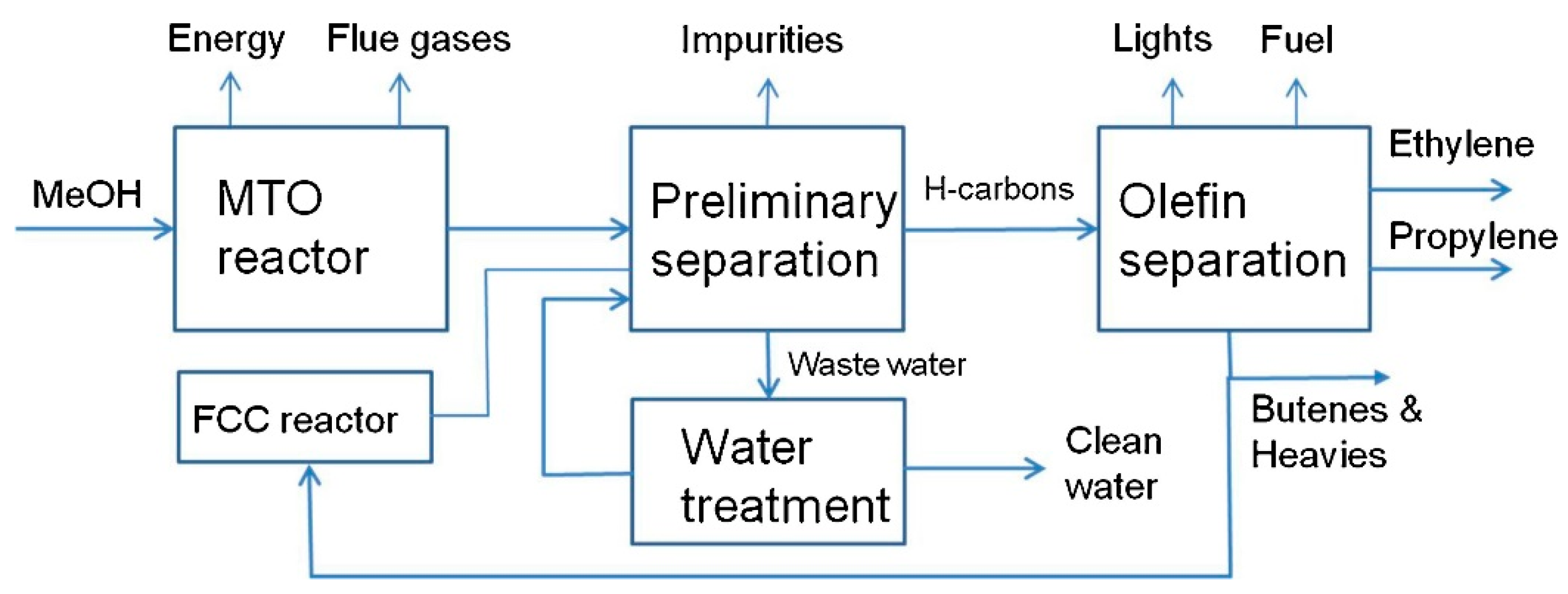
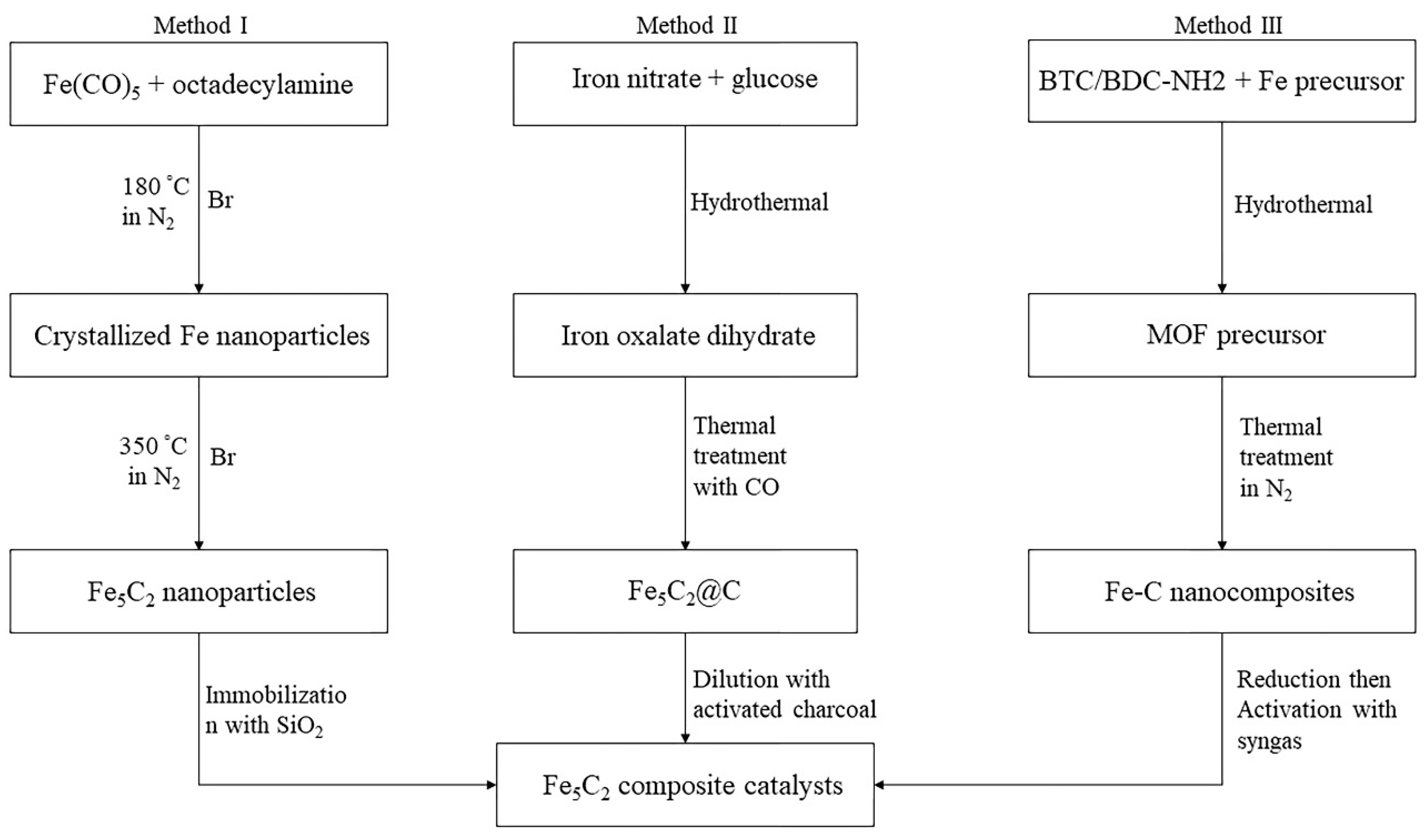
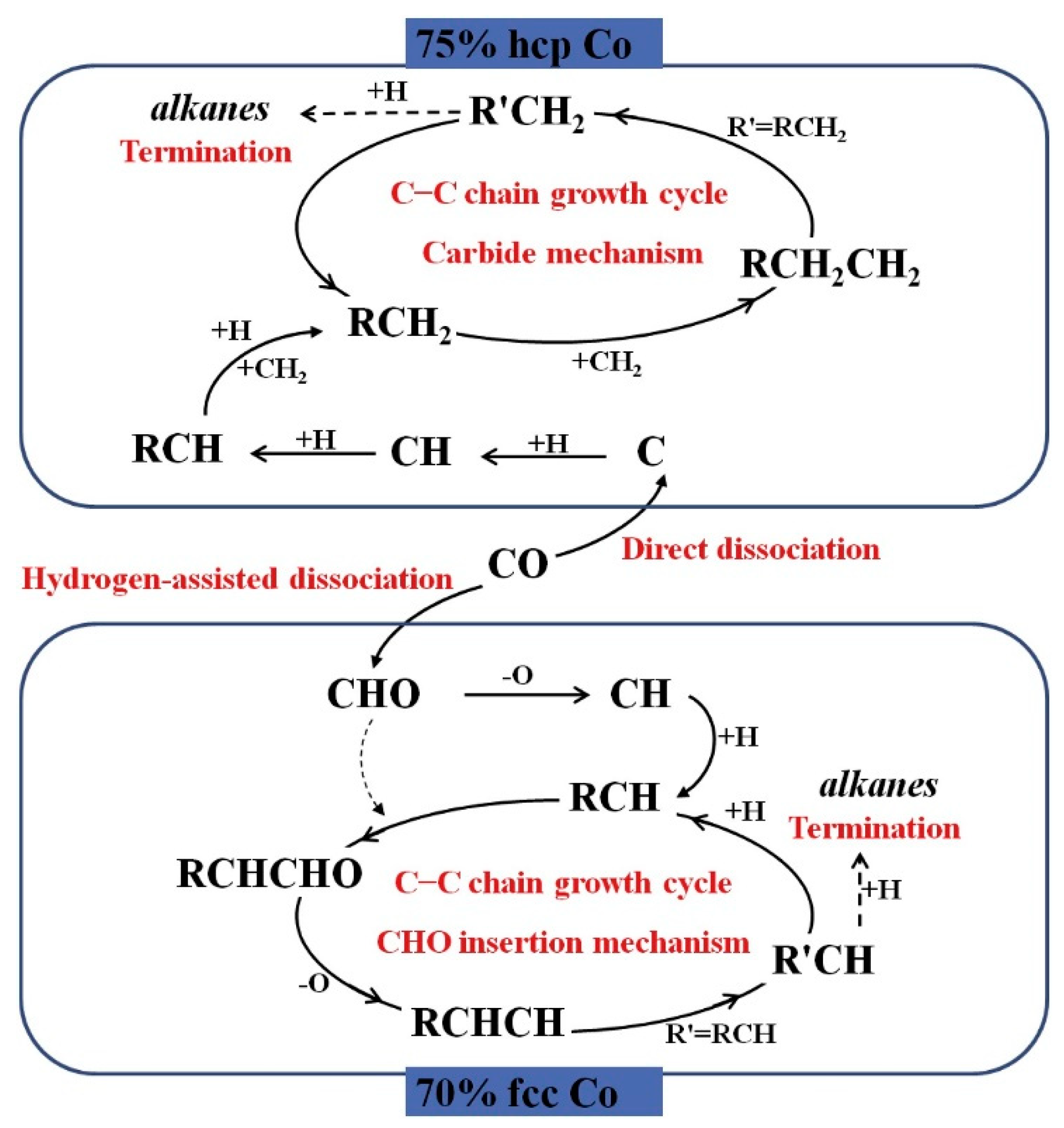
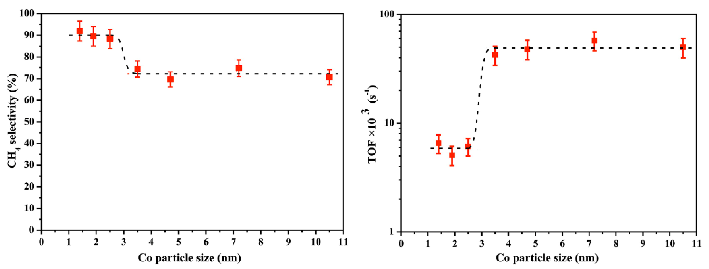
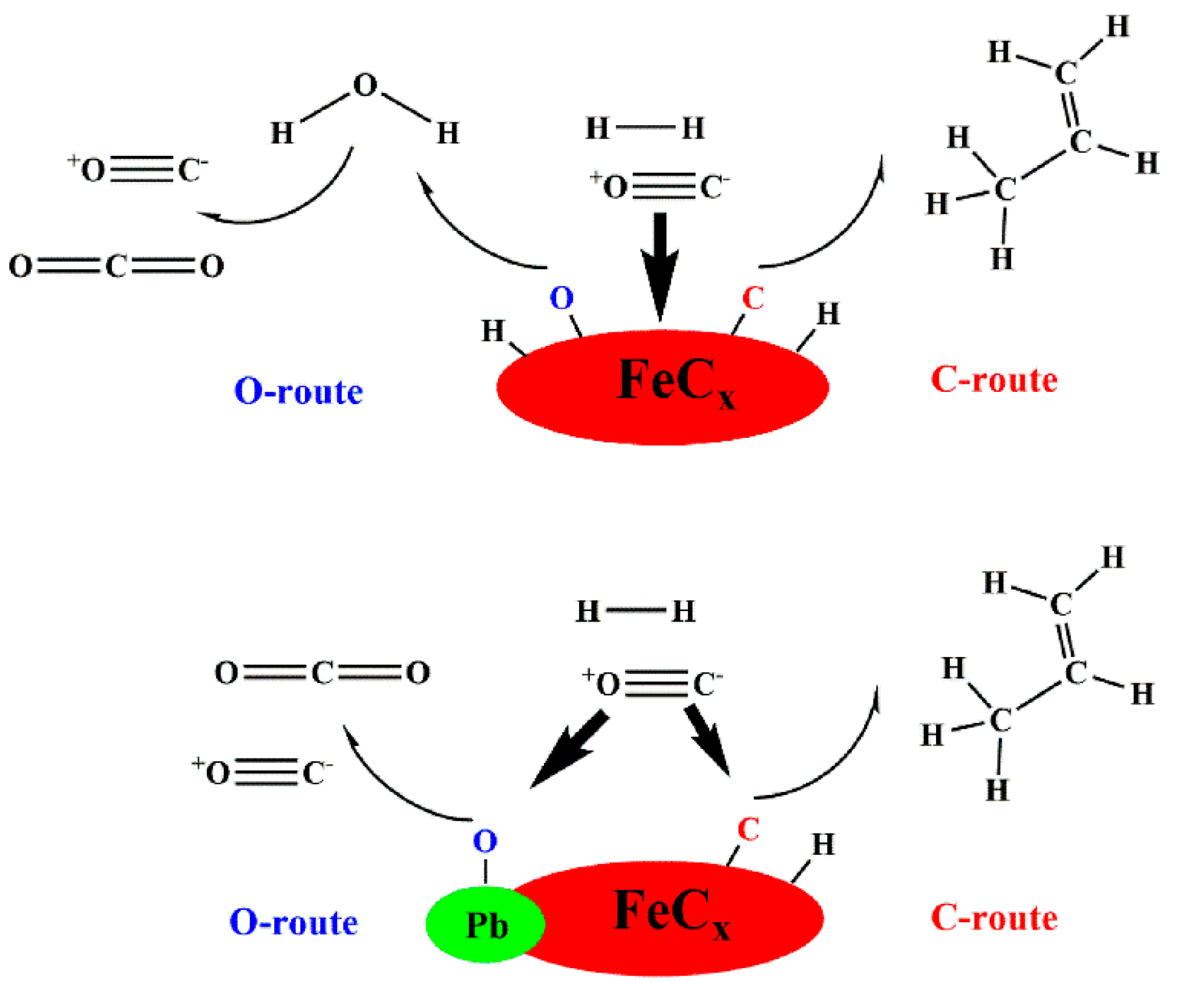
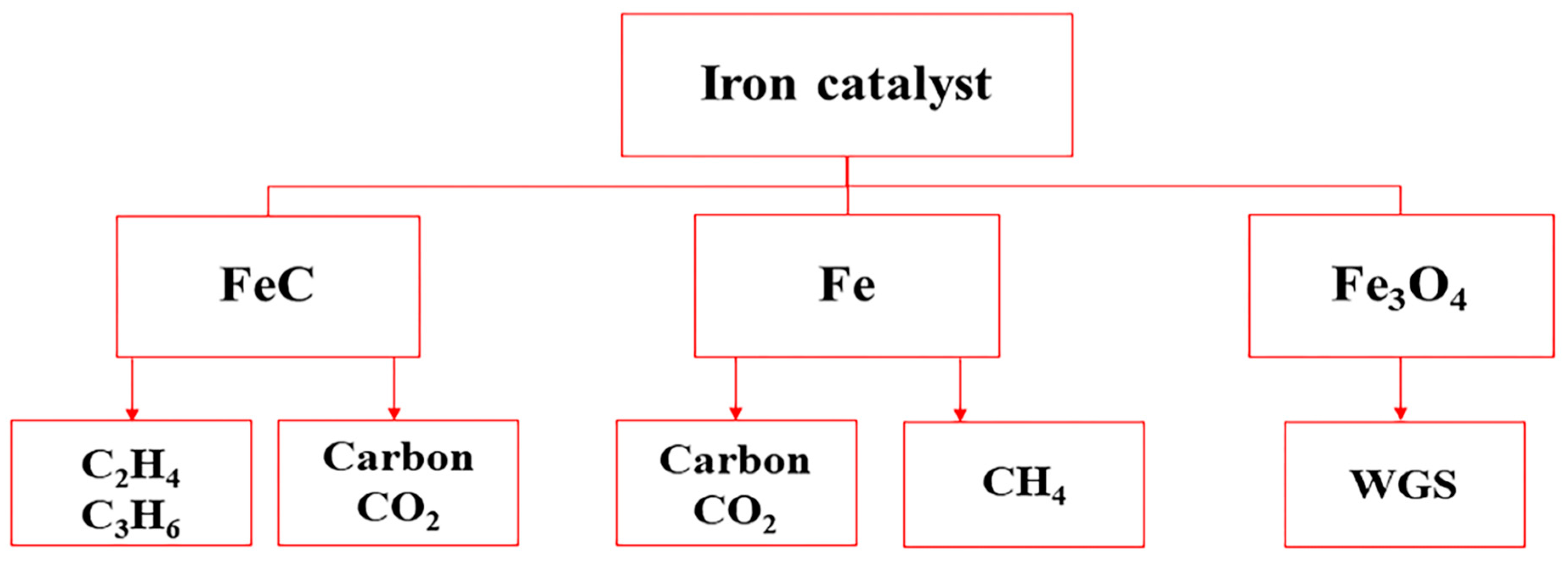
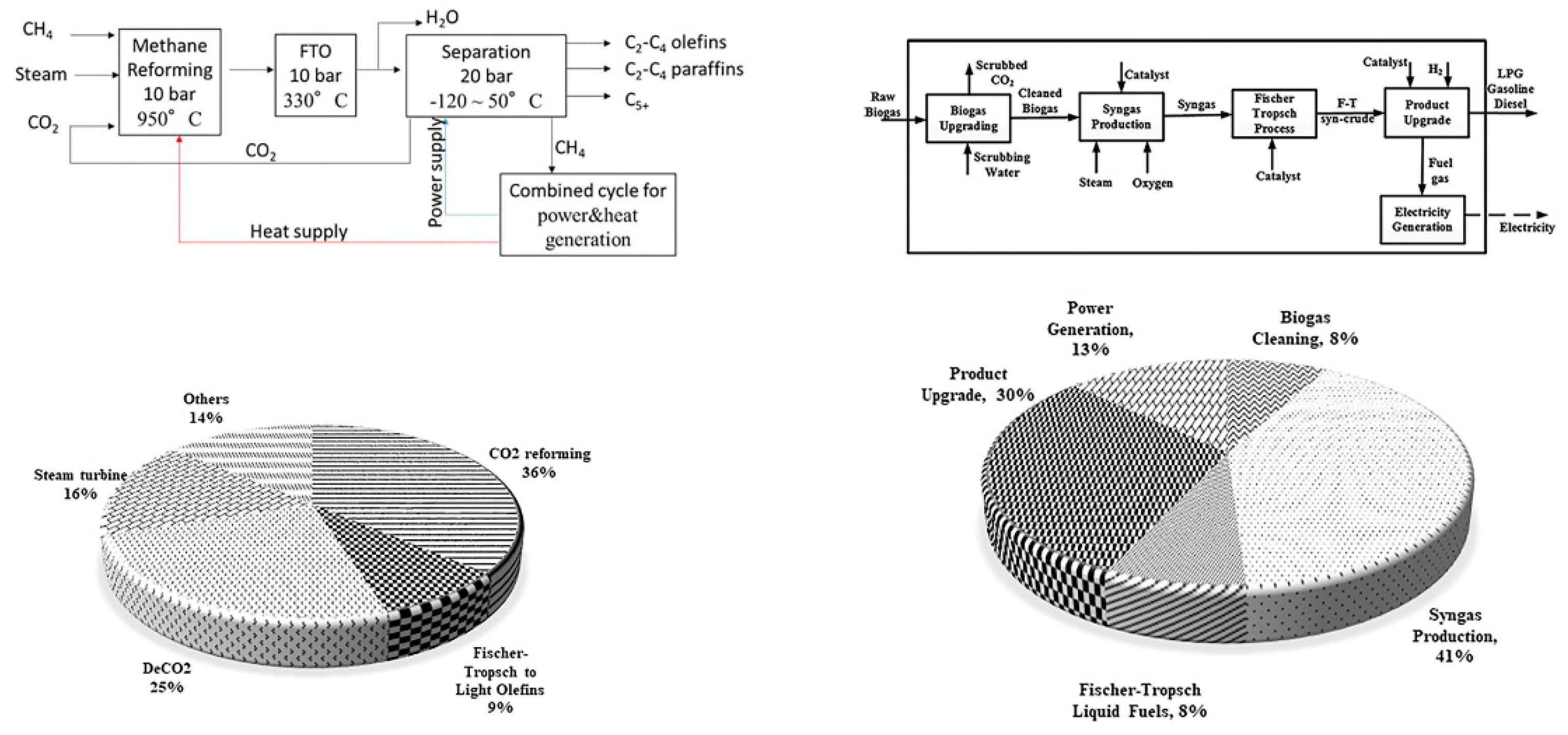
| Company | Carbon Source | Capacity (bpd) | Commissioning Date |
|---|---|---|---|
| Sasol | Coal | 2500 | 1955 |
| Sasol | Coal | 85,000 | 1980 |
| Sasol | Coal | 85,000 | 1982 |
| MossGas | Natural gas | 30,000 | 1992 |
| Shell | Natural gas | 12,500 | 1993 |
| Sasol/Qatar Petroleum | Natural gas | 34,000 | 2006 |
| Sasol Chevron | Natural gas | 34,000 | 2007 |
| Shell | Natural gas | 140,000 | 2009 |
| Sasol/USA | Natural gas | 96,000 | 2018 |
| Sasol/Canada | Natural gas | 96,000 | 2020 |
Table 2.
Different synthesis methods of Fe-based catalysts for FTO.
| Active Metal | Support | Promoter | Synthesis Method | Active Phase | C2-C4 Selectivity (%) | CO Conversion (%) | Reference |
|---|---|---|---|---|---|---|---|
| Fe | CNTs | Mn/K | Impregnation | FeMn2O4 before reduction | 51.7 | 30.1 | [23] |
| Fe Fe | CNTs CNTs | Bi Pb | Impregnation | Hägg χ-Fe5C2 or ε-Fe2C | 60.9 57.7 | 10.0 18.6 | [24] |
| Fe Fe | CNTs CNTs | Bi Pb/K | Impregnation | χ-Fe5C2 | 45–62.4 52.6–62 | 25.5–25.6 40.7–76.2 | [25] |
| Fe | CNTs | Mn/K | Impregnation | Hägg χ-Fe5C2 | 50.3 | 22.7 | [26] |
| Fe-Zn-Cu Fe | - CNTs | - K | Co-precipitation Deposition-precipitation | - | 35 42 | 45 16 | [27] |
| Fe | N-CNTs a | K | Impregnation | χ-Fe5C2 | 54.6 | 14.4 | [28] |
| Fe | NMCs b | - | Ultrasonic-impregnation | Fe5C2 and Fe2C | 33.9 | 92.6 | [29] |
| Fe-Cu | Graphite | - | Co-precipitation | Fe7C3 | 37.8 | 44.9 | [30] |
| Fe Fe Fe Fe Fe Fe Fe Fe | AC CSiO2 c CSiO2 c SiC SiC γ-Al2O3 SiO2 TiO2 | K K K/S Na/S K - - K | Impregnation | χ-Fe5C2 and ε’-Fe2.2C | 21.7 26.5 51.7 51.4 19.7 16.1 19.5 17.3 | 48.9 32.2 11.8 10.3 57.1 10.0 16.7 67.7 | [31] |
| Fe Fe Fe Fe | mSiO2 d SiO2 SiO2-CO e SiO2-H2 e | - - - - | Impregnation | χ-Fe5C2 is dominant (above 36%) Fe3C and ε-Fe2.2C are low (less than 14%) | 12.8 15.2 18.3 14.1 | 15.4 28.5 76.9 51.6 | [21] |
| Fe | SiO2-E f | Mn | Impregnation | - | 54.6 | 50.5 | [32] |
| Fe Fe-Cu Fe Fe-Cu | SiO2 SiO2 SiO2 SiO2 | - - K K | Impregnation Co-impregnation Impregnation Co-impregnation | χ-Fe5C2 | 10.1 15.2 18.7 18.1 | 23 33.9 29.9 34.3 | [18] |
| Fe Fe | SiO2 SiO2 | Bi Pb | Impregnation | χ-Fe5C2 | 53 32 | 17 55 | [33] |
| Fe Fe2O3 | SiO2-GC g SiO2 | - - | Hydrothermal deposition | Hägg χ-Fe5C2 | 12.9 17.4 | 40.6 40.6 | [34] |
| Fe-Mn | SiO2 | Cu | Co-precipitation, impregnation | Hägg χ-Fe5C2 | 40.1 | 96.9 | [35] |
| Fe Fe Fe | Si-CO e Si-H2 e Si-Syngas e | - - - | Co-precipitation | Fe7C3, χ-Fe5C2 ε-Fe2C, χ-Fe5C2 χ-Fe5C2 | 30.8 15.0 17.1 | 50.8 33.1 22.3 | [22] |
| Fe | α-Al2O3 | S/Na | Impregnation | - | 50 | 66 | [20] |
| Fe-Ni | Al2O3 | K2S | Co-precipitation | - | 77.8 | 64.6 | [36] |
| Fe Fe Fe Fe | MgO-NS h MgO-NS MgO-NS MgOcubes | - - - - | Impregnation Deposition-precipitation Ultrasonic impregnation Ultrasonic impregnation | - | 14.6 15.5 29.6 21.5 | 55.6 38.0 35.5 35.7 | [37] |
| Fe | MnOx | Ag | Impregnation | χ-Fe5C2 | 35.4 | 50.3 | [38] |
| Fe | - | Na/S | Precipitation | - | 66 | 30 | [39] |
| Fe Fe Fe Fe Fe | - - - - - | - Na K Zn Mn | Solvothermal | - | 19.3 23.3 22.1 18.1 34.1 | 91.0 93.2 97.1 98.3 37.4 | [40] |
| Fe Fe | - - | Zn/Na Zn/K | Co-precipitation | - | 42.7 37.19 | 97.16 5.02 | [41] |
| Fe | - | Zr | Co-precipitation | - | 57 | 40.6 | [42] |
a Nitrogen-doped CNTs; b Nitrogen-rich mesoporous carbon-supported Fe catalyst; c Carbon-coated SiO2; d Mesoporous silica; e Fe-Si calcined catalyst treated with CO, H2, and syngas; f Ethylene glycol pretreated silica support; g Silica-graphitic carbon encapsulated iron; h Nanosheet.
Table 3.
Different synthesis methods of Co-based catalysts for FTO.
| Active Metal | Support | Promoter | Synthesis Method | C2-C4 Selectivity (%) | CO Conversion (%) | Reference |
|---|---|---|---|---|---|---|
| Co Co | MHZSM 5 a HZSM 5 | - - | - | 29.1 30.9 | 79.0 75.9 | [47] |
| Co | Al2O3/ZSM 5 | La | Co-precipitation | 24.1 | 20.7 | [48] |
| Co Co | γ-Al2O3 γ-Al2O3-PT b | Ru/La Ru/La | Impregnation | 11.2 15.9 | 45.8 43.7 | [49] |
| Co-Mn | γ-Al2O3 | - | Co-impregnation | 8–11 | 20–45 | [50] |
| Co Co | Al2O3 Al2O3 + Pt/Al2O3 | - Pt | Impregnation | 44.8–50.4 46.2–59.2 | 9.5 13 | [51] |
| Co-Ni | mSiO2 c | - | Impregnation | 26.8 | 19.7 | [52] |
| Co-Mn-Ce | SiO2 | - | Impregnation | 17.4 | 10.1 | [53] |
| Co | Mn/SiO2 | Zn/Ce | Impregnation | 10–36 | 17–31.8 | [54] |
| Co | MnOx | - | Co-precipitation | 26.5–42.2 | 42.3–45.3 | [55] |
| Co-Mn | - | - | Co-precipitation | 50 | 2.5 | [56] |
| Co-Mn | - | - | Co-precipitation | 37.7 | 30 | [57] |
| Co Co Co | TiO2 TiO2@mSiO2 c TiO2@mSiO2 | - - Ru | Deposition precipitation | 10.6–20.9 5.2–21.7 12.1–23.3 | 27.5–33.1 17–46.1 31.6–58.9 | [58] |
| Co Co | TiO2-C d TiO2-P e | Pt Pt | Co-impregnation | 5.4 6.2–7.0 | 28.6 66.3 | [59] |
| Co | TiO2 TiO2 | - Ru | Impregnation | 32.3 27.2–29.9 | 24.3 82.3–98.3 | [60] |
| Co | C f | - | - | 10.87–11.87 | 34.15–35.62 | [61] |
| Co-Mn | Al2O3 GNS g rGO h | - - - | Impregnation | 14–28 22–42 25–53 | 21–37 5.4–39.2 20.5–33.2 | [7] |
| Co-Mn | GNS g | - | Impregnation | 29.2 | 49 | [62] |
| Co | CNT | - | Impregnation | 29.5–18.9 | 84–75 | [63] |
| Co Co | CNT-800 i CNT-1000 | - - | Impregnation, Spark plasma sintering | 8.1 20.3 | 14.9 34.5 | [64] |
a Hierarchical HZSM-5 zeolite support; b Acetylene pretreated catalyst; c Mesoporous silica (mSiO2); d Calcined CoPt/TiO2; e Plasma treated CoPt/TiO2; f Cobalt catalyst embedded in nanoporous carbon; g Graphene nanosheet; h Reduced graphene oxide; i Sintering temperature (800 and 1000 °C).
Table 4.
Techniques for investigating the basicity and reducibility of FTS catalysts.
| Catalyst | Technique | Note | Reference |
|---|---|---|---|
| Fe/MgO a | CO2-TPD b | Surface basicity of catalyst based on desorption peaks: Moderate alkaline sites (Mg2+/O2+) around 160–400 °C Strong basic sites (unsaturated O2−) above 400 °C MgO nanosheet: Mg2+/O2+ around 350 °C Unsaturated O2− nearly 600 °C For Fe/MgO-c-UI, the ratio of medium/strong basicity is higher than that of Fe/MgO-ns-UI | [37] |
| Unmodified Fe ore K/Cu/iron ore Fe/Cu/K/SiO2 c | CO2-TPD | CO2 adsorbed on the alkali surface: 22 μmol/g 100 μmol/g 129 μmol/g Iron ore-based catalysts contain Al2O3 which is more acidic than SiO2 | [71] |
| Alkali promoted Fe/SiO2 | H2-TPR d | Reducibility of catalysts based on alkali type: The First step reduction: The lower temperature peak: Fe2O3 → Fe3O4 The first step reduction temperature increase in the order of Li > Na > K > Rb > Cs Subsequent reduction: The higher temperature peaks: Fe3O4 → FeO and FeO → α-Fe | [72] |
| K/α-Fe2O3 | H2-TPR | Reducibility of catalysts based on amount of alkali: The first reduction temperatures shift to higher temperature by increasing potassium levels. The second reduction temperatures decrease with increasing potassium. | [73] |
a Fe catalyst supported on MgO nanosheet (Fe/MgO-ns) and cubes (Fe/MgO-c) synthesized by ultrasonic impregnation (UI) method; b CO2-temperature programmed desorption; c Precipitated Fe/Cu/K/SiO2 catalyst; d H2-temperature programmed reduction.
Table 5.
Techniques for investigating the dispersion of active metal in catalysts.
| Catalyst | Technique | Dispersion (%) | C2-C4 Selectivity (%) | Note | Reference |
|---|---|---|---|---|---|
| Co/TiO2 Co/TiO2@mSiO2 a CoRu/TiO2@mSiO2 | Pulse Chemisorption | 4.5–1.9 3.6–3.7 5.0–6.7 | 10.6–20.9 5.2–21.7 12.1–23.3 | TChemisorption = 350–450 °C FTS (T = 220–250 °C, P = 10 bar, H2/CO = 2, GHSV = 800 mLg−1h−1) | [58] |
| Co/CNT | H2−TPD | 8.2–10.8 | 29.5–18.9 | FTS (T = 220 °C, P = 20 bar, H2/CO = 2, GHSV = 40 mLg−1h−1) | [63] |
| CoPt/TiO2-C b CoPt/TiO2-P1 c CoPt/TiO2-P3 CoPt/TiO2-P4 | H2−TPD O2−titration | 20.4 26.9 27.8 73.7 | 5.4 6.2 6.5 7.0 | FTS (T = 210 °C, P = 10 bar, H2/CO = 2, GHSV = 4 SLg−1h−1) | [59] |
| 0CTAB-Co@C d 2CTAB-Co@C 4CTAB-Co@C 8CTAB-Co@C | H2−TPD | 32.05 20.07 37.07 38.51 | 10.87 11.87 11.21 11.27 | FTS (T = 230 °C, P = 20 bar, H2/CO = 2, GHSV = 6.75 SLg−1h−1) | [61] |
a Mesoporous silica (mSiO2); b Calcined CoPt/TiO2; c Plasma treated CoPt/TiO2 for 1, 3, and 4 h; d Co catalyst embedded in nanoporous carbon with m(CTAB)/n(Co) = 0, 2, 4, 8; Cetyltrimethyl ammonium bromide (CTAB).
Table 6.
Light olefin selectivity of different Fe-based catalysts in FTO.
| Catalyst | Promoter | T (°C) | P (bar) | GHSV (Lh−1g−1) | H2/CO | C2-C4 Selectivity (%) | CO Conversion (%) | Reference |
|---|---|---|---|---|---|---|---|---|
| Fe/α-Al2O3 | S/Na | 340 | 20 | 3 | 1 | 50 | 60–66 | [20] |
| Fe/α-Al2O3-H a | S | 350 | 1 | 9 | 1 | 68 | 0.9 | [86] |
| Fe-Ni/Al2O3 | K2S | 340 | 1 | 3 | 2 | 77.8 | 64.6 | [36] |
| Fe/CNTs | Mn/K | 270 | 20 | 30 | 1 | 51.7 | 30.1 | [23] |
| Fe/CNTs | Bi Pb | 350 350 | 1 1 | 3.4 3.4 | 1 1 | 60.9 57.7 | 10 18.6 | [24] |
| Fe/CNTs-Confined b | Bi Bi Pb/K Pb/K | 350 350 350 350 | 10 1 10 1 | 17 3.4 17 3.4 | 1 1 1 1 | 45 62.4 52.6 62 | 60.2 25.6 76.2 40.7 | [25] |
| Fe/CNTs c | Mn/K | 270 | 20 | 30 | 1 | 50.3 | 22.7 | [26] |
| Fe/N-doped CNTs Fe/N-doped CNTs | - K | 300 300 | 1 1 | 4.2 4.2 | 1 1 | 46.7 54.6 | 14.4 16.5 | [28] |
| Fe/NMCs d | - | 340 | 10 | - | 1 | 33.9 | 92.6 | [29] |
| Fe/CNTs | K | 270 | 20 | 18 | 1 | 42.2 | 28.8 | [85] |
| Fe/CNF | Na/S | 350 | 1.85 | 12–24 | 10 | 50 | 10 | [87] |
| Fe/AC Fe/CSiO2 e Fe/SiC | K K Na/S | 300 300 300 | 10 10 2 | 2.2 2.2 2.2 | 1.1 1.1 1.1 | 21.7 26.5 51.4 | 48.9 32.2 10.3 | [31] |
| Fe/SiO2-E f | Mn | 300 | 10 | - | 1 | 54.6 | 50.5 | [32] |
| Fe/SiO2 | - Cu K Cu/K | 300 300 300 300 | 20 20 20 20 | 16 16 16 16 | 2 2 2 2 | 10.1 15.2 18.7 18.1 | 23 33.9 29.9 34.3 | [18] |
| Fe/SiO2 | Bi Pb | 350 350 | 1 1 | 3.4 3.4 | 1 1 | 53 32 | 17 55 | [33] |
| Fe/MnOx | Ag | 340 320 | 10 10 | 7.4 7.4 | 1.1 1.1 | 35.4 34.3 | 50.3 55 | [38] |
| Fe/MgO nanosheets Fe/MgO cubes | - - | 300 300 | 10 10 | 8 8 | 1 1 | 14.6–29.6 21.5 | 35.5–55.6 35.7 | [37] |
| Fe-Cu/Graphite | - | 260 | 20 | - | 1.1 | 37.8 | 44.9 | [30] |
| Fe | Na/S | 330 | 20 | 12.9 | 4 | 64.24 | 25 | [39] |
| Fe | - Na K Zn Mn | 280 280 280 280 280 | 20 20 20 20 20 | 3 3 3 3 3 | 1 1 1 1 1 | 19.3 23.3 22.1 18.1 34.1 | 91 93.2 97.1 98.3 37.4 | [40] |
| Fe | Zn/Na Zn/K | 350 350 | 20 20 | 3 3 | 2.7 2.7 | 42.7 37.19 | 95.09 95.02 | [41] |
| Fe | Zr | 280 | 10 | - | 1 | 57 | 40.6 | [42] |
| Mo/γ-Al2O3 | K | 300 | 10 | 6 | 2 | 21.8 | 4.2 | [88] |
a Hierarchical α-Al2O3 support; b Iron nanoconfinement inside carbon nanotubes; c Supercritical hexane with hexane/syngas ratio of 3; d Nitrogen-rich mesoporous carbon-supported Fe catalyst; e Carbon-coated SiO2; f Ethylene glycol pretreated catalyst.
Table 7.
Light olefin selectivity of different Co-based catalysts in FTO.
| Catalyst | Promoter | T (°C) | P (bar) | GHSV (Lh−1g−1) | H2/CO | C2-C4 Selectivity (%) | CO Conversion (%) | Reference |
|---|---|---|---|---|---|---|---|---|
| Co-Meso-HZSM 5 a Co-HZSM 5 | - - | 240 240 | 1 1 | - - | 2 2 | 29.1 30.9 | 79 75.9 | [47] |
| Co/γ-Al2O3 Co/γ-Al2O3-PT b | Ru/La Ru/La | 220 220 | 20 20 | 4–6 4–6 | 2 2 | 11.2 15.9 | 45.8 43.7 | [49] |
| Co/γ-Al2O3 | Mn | 240 | 5 | - | 2.1 | 8–11 | 20–45 | [50] |
| Co-Al2O3/ZSM 5 | La | 240 | 20 | 4 | 2 | 24.1 | 20.7 | [48] |
| Co/MnOx Co/MnOx-BDO c | - - | 240 240 | 10 10 | 2.5 2.5 | 2 2 | 26.5 42.2 | 45.3 42.3 | [55] |
| Co-Mn/SiO2 | Zn/Ce | 260 | 1 | 4.5 | 1 | 10–36 | 80–90 | [54] |
| Co/Al2O3 Co/Al2O3 + Pt/Al2O3 | - Pt | 220 220 | 20 20 | 144 144 | 2 2 | 44.8–50.4 46.2–59.2 | 9.5 13 | [51] |
| Co/TiO2 Co/TiO2@mSiO2 d Co/TiO2@mSiO2 | - - Ru | 220–250 220–250 220–250 | 10 10 10 | 0.8 0.8 0.8 | 2 2 2 | 10.6–20.9 5.2–21.7 12.1–23.3 | 18.6–36.6 17–46.1 31.6–58.9 | [58] |
| Co/CNT | - | 220 | 20 | 0.04 | 2 | 18.9–29.5 | 5–84 | [63] |
| Co/CNT | - | 240 | 20 | 5 | 2 | 8.1–20.3 | 34.5–66.7 | [64] |
| CoPt/TiO2-C e CoPt/TiO2-P1 f CoPt/TiO2-P3 CoPt/TiO2-P4 | - - - - | 210 210 210 210 | 10 10 10 10 | 4 4 4 4 | 2 2 2 2 | 5.4 6.2 6.5 7.0 | 19.9 48.2 39.6 3.4 | [59] |
| 0CTAB-Co@C g 2CTAB-Co@C 4CTAB-Co@C 8CTAB-Co@C | - - - - | 230 230 230 230 | 20 20 20 20 | 6.75 6.75 6.75 6.75 | 2 2 2 2 | 10.87 11.87 11.21 11.27 | 35.62 34.15 36.20 40.08 | [61] |
a Hierarchical HZSM-5 zeolite support; b Acetylene pretreated catalyst; c 1,4-Butanediol (BDO) was used as solvent for catalyst precursors; d Mesoporous silica (mSiO2); e Calcined CoPt/TiO2; f Plasma treated CoPt/TiO2 for 1, 3, and 4 h; g Cobalt catalyst embedded in nanoporous carbon with m(CTAB)/n(Co) = 0, 2, 4, 8).
Table 8.
Deactivation of catalysts in Fischer–Tropsch synthesis.
| Catalyst | Time (h) | C2-C4 Selectivity (%) | Deactivation | Reference |
|---|---|---|---|---|
| FeZnNa/zeolite | 100 | 46.1 | Carbon deposition suggested by Raman spectroscopy | [91] |
| Co/SiO2 | 46–50 46–50 | 11 at 220 °C 14.5 at 240 °C | -At 240 °C, oxidation of metallic Co -At 220 °C, blocking of pore channel and active sites with heavier hydrocarbon -Note that with increasing thickness of SiO2 shell, the average pore size decreases accelerating deactivation | [92] |
| Co-Al2O3/SiO2 | 500 | 7 | -Carbonization -Pore clogging by heavy hydrocarbons resulted in the decreased specific surface area -Agglomeration of cobalt crystallite | [93] |
| FeCuK/SiO2 | 5000–10000 | 2.73–10.14 | Carbon deposition confirmed by XRD | [94] |
| FeMn-HZSM-5 FeK-HZSM-5 | - - | 28.5 6.4 | -Coke deposition -Heavy hydrocarbon over FeK catalyst | [89] |
| Fe-Zr | 10 | 57 | -Surface enriching of Zr covering iron carbide active sites based on XPS results | [42] |
| FeKS/CSiO2 a | 10 | 47.7–51.7 | -K-induced carbon deposition -Oxidation of χ-Fe5C2 to Fe3O4 | [31] |
| Fe-Si-Cu-Rb Pt-Co/Al2O3 | 573–662 1254–1327 | 25.7 at 100 ppm KCl 9.11 at 50 ppm KCl | -Investigating KCl poisoning -Site blocking by K and Cl ions -Electronic modification affecting CO/H2 adsorption | [95] |
| Pt-Co/Al2O3 | - | 7.3 at 1000 ppm NH3 | Investigating ammonia poisoning -Cobalt nitride formation -Decreasing selectivity from 10.5 to 7.3 | [96] |
a Carbon-coated SiO2.
Table 9.
Techno-economic assessment of Fischer–Tropsch synthesis.
| Process-Catalyst | Notes | Reference |
|---|---|---|
| FTS-Bioethanol plant -Fe/CNT pellet catalyst | -Conversion of biomass-derived syngas to syncrude (biogasoline and biodiesel) -Reactant flow: 3305 kg syngas/h, product capacity: 1000 kg syncrude/h -Net annual profit: 5.2 MUSD/year, internal rate of return: 107.9% -Environmental friendly process | [109] |
| FTS -Fe and Co catalyst | -Conversion of biomass to FT liquids -Overall thermal efficiency of biomass to FT liquids considering electricity output was in the range of 41.3–45.5% for Fe- and Co-based catalyst. -Co-feeding of natural gas and biomass reduces costs of biomass pretreatment and gasification. -Co-feeding of natural gas and biomass reduces costs of FT liquids about 30% (from $28.8 to $19–$20 per GJ of FT liquids). -Production of FT biofuels at oil price of $60/barrel is not economically feasible. | [108] |
| LTFT and SCWRa -Not mentioned | -Integrating LTFT with SCWR of bio-oil aqueous phase to produce biofuels and electricity -Plant capacity: 60 t/h, feeding concentration: 25 wt%, return rate: 10% -FT liquids: 0.93 Є/kg diesel, 0.26 Є/kg jet fuel, 1.20 Є/kg gasoline -Electricity selling price: 0.17 Є/kWh -Decrease in selling price by increasing plant size (20–200 t/h) | [110] |
| FTS and co-electrolysis b -Co catalyst | -Fuel production via Power-to-X process -Reduced numbers of reactors and heat exchanger compared to Power-to-X technologies b -Overall energetic efficiency: 68% (62% considering heat losses) -Focus on valuable products like waxes favors economic feasibility -Capital expenditure of the plant: 194,000 Є/bpd which is higher than that of commercial plants, e.g., Velocys (90,000 Є/bpd), Shell/Pearl (122,000 Є/bpd), and Sasol/Oryx (25,000–44,000 Є/bpd) -Availability and cost of renewable electricity affect the production cost | [111] |
| FTS -Not mentioned | -Conversion of lignite and woody biomass to jet fuel and electricity -Plant profitability is sensitive to biomass input fraction -High moisture content of biomass (43%) causes energy penalty -Co-firing of lignite and biomass is less profitable than solely biomass -Carbon-negative plants (only biomass input) are economically feasible at oil prices below $100/bbl with carbon emission price above $120/tonne CO2eq | [112] |
| FTS and DMTM c -Co catalyst | -Conversion of natural gas into liquid products -Unit cost of DMTM process is sensitive to the methane recycle ratio -Unit cost of FTS in MCR is less sensitive to the tailgas recycle ratios -Higher energy requirements compared to conventional GTL technologies d -For internal rate of return (IRR) above 10%, tailgas recycle ratio has to be above 8% at CO conversion of 80%, while the minimum methane recycle ratio of 60% is required for profitability -For profitability index (PI) >1, tailgas recycle ratio of 15% (at CO conversion of 80%) and minimum methane recycle ratio of 55% is required e | [113] |
| FTS, MTG, TIGAS f -Co catalyst | -Conversion of biomass to liquid hydrocarbon fuels via Biomass-to-liquid (BTL) process -Modelling of BTL systems for gasification of woody biomass -Overall energy efficiency of BTL: 37.9–47.9% lower heating value (LHV) -Production costs of BTL: 17.88–25.41 Є per GJ of produced fuels -BTL production costs is 8% higher than current market prices | [114] |
| FTS -Barium zirconate-based perovskite-type catalyst | -Conversion of H2 + CO2 to FT liquid fuels via electricity generated from renewable source -CO2 and H2 are provided by ethanol plant and electrolysis, respectively. -H2 price ($2/kg via electrolysis in 2020) has the largest impact on the minimum selling price of FT fuel ($5.4–5.9/gal) -Conversion of 223 metric ton H2/day and 2387 metric ton CO2/day into 351 metric ton/day of liquid FT fuel obtains overall energy efficiency of 57.5% LHV and 52.2% HHV g -CO2 and H2 prices are required to be $17.3/metric ton CO2 and $0.8/kg H2 to be cost-competitive with petroleum diesel price of $3.1/gal in 2050 | [115] |
| FTO h -FeMnCuK -Fe2O3 | -Conversion of natural gas into light olefins -Capital expenditure of the FTO plant: 170.8 MM$ for treatment of (360 MT/day and 18,849 MMBtu/day) of natural gas -Internal rate of return for FeMnCuK-based FTO plant: 20% -The levelized production cost: $679/MT in year 2012 | [103] |
| FTS -Not mentioned | -Conversion of biogas to drop-in diesel fuel in biogas-to-liquid (BgTL) plant -Minimum selling price of the FT drop-in fuels: $5.67/gal (feed capacity:2000 Nm3/h) -Increasing feed capacity to 20,000 Nm3/h reduces minimum selling price to $2.06/gal | [107] |
| FTS - | -Co-conversion of natural gas and biomass to transportation fuels -Hydrocracker increases the production of diesel and jet fuels -Minimum fuel selling price: $2.17–3.60 and $2.47–3.47 per GGE i with and without hydrocracker, respectively | [45] |
a Low-temperature Fischer–Tropsch and supercritical water reforming; b Coupling of electrolysis and a chemical synthesis step; power-to-gas, power-to-fuel, power-to-chemicals; c FTS in microchannel reactor (MCR) and direct methane to methanol;d Gas-to-liquid; e Profitability index is the ratio of net present value to fixed capital investment (PI = NPV/FCI); f Methanol-to-gasoline (MTG) and the Topsoe integrated gasoline synthesis (TIGAS); g Higher heating value; h FT synthesis to light olefins; i Gallon gasoline equivalent.
Table 10.
Lifecycle assessment of Fischer–Tropsch synthesis.
| Process | Notes | Reference |
|---|---|---|
| BDR a, FTS | -Conversion of biogas to liquid fuels -Functional unit of the LCA study is defined as 1 kg of synthetic biodiesel produced at plant -Lifecycle environmental profile of synthetic biodiesel is calculated and compared with conventional diesel -Evaluation of the plant in terms of global warming, cumulative non-renewable energy demand, ozone layer depletion, acidification, and eutrophication | [119] |
| LTFT HTFT b | -Conversion of coal to FT oil -Study focused on LCA of energy use, CO2 emission and cost input of FTS from coal and its competitor -Mining and washing of coal, and oil production cause the energy input and CO2 emission -The FTS plant from coal to oil is not beneficial compared to oil refinery pathway in terms of energy use and greenhouse gases emission | [117] |
| Gasification FTS | -Conversion of biomass to FT jet fuel -Lifecycle includes the stages of biomass growth, collection, transportation, plant construction and demolition, production, product distribution, and consumption -Application of steam for heat supply (case1) and power generation (case2) -Cases1 and 2 are better than the commercial plant due to reduced nonrenewable resource consumption and pollutant emissions, while production costs increase. -The pollution mitigation benefit of case1 and 2 are small, the consumption of CO2 is much fewer than in traditional processes -Case1 and 2 are sensitive to consumption of electricity and stalk, respectively | [120] |
| SCWR c LTFT HT c | -Production of biofuels via SCWR-LTFT and HT which process bio-oil aqueous phase and oil phase, respectively -Estimating the cradle-to-gate environmental impacts especially the global warming potential (GWP) -Hot water produced in the process is considered as a co-product to be used for district heating. The impact of catalyst is accounted for in the process to produce biofuels | [121] |
| FTS | -Conversion of H2 and CO2 into FT fuels -H2 is provided by water electrolysis with electricity from solar, wind, and nuclear sources -CO2 is provided by corm ethanol industry byproduct -investigation of greenhouse gas (GHG) emissions of FT fuel plant -Environmental impacts and GHG emissions of FT fuel plant are evaluated using GREET 2020 model d -Energy efficiency of FT fuel production: 58% | [122] |
| FTS | -Conversion of miscanthus biomass to biogas via anaerobic digestion -Production of drop-in FT biodiesel by FTS -Focus on emission of CO2, CH4, and NOx which contributes to global warming potential -Compared to commercial plants, the drop-in FT biodiesel reduces both GHG emissions (by 73%) and fossil fuel depletion (4.91 MJ/GGE), while potential of respiratory impacts, smog formation, acidification, and eutrophication is higher. | [123] |
| DAC e, FTS | -Conversion of CO2 (obtained by DAC) and H2 (obtained by electrolysis) into FT biodiesel -Evaluation of GHG emissions from the DAC-FTS to biodiesel plant -The electricity emissions factor used in the process is relatively low -The biodiesel plant is suggested to be conducted in regions with very low grid emission factors -The biodiesel is suggested to be co-located with a renewable energy facility | [124] |
a Biogas dry reforming; b Low-temperature and high-temperature Fischer–Tropsch synthesis; c Supercritical water reforming and hydrotreating; d Greenhouse gases, regulated emissions, and energy use in transportation; e Direct air capture system.
Publisher’s Note: MDPI stays neutral with regard to jurisdictional claims in published maps and institutional affiliations. |
© 2021 by the authors. Licensee MDPI, Basel, Switzerland. This article is an open access article distributed under the terms and conditions of the Creative Commons Attribution (CC BY) license (https://creativecommons.org/licenses/by/4.0/).
Share and Cite
MDPI and ACS Style
Yahyazadeh, A.; Dalai, A.K.; Ma, W.; Zhang, L. Fischer–Tropsch Synthesis for Light Olefins from Syngas: A Review of Catalyst Development. Reactions 2021, 2, 227-257. https://0-doi-org.brum.beds.ac.uk/10.3390/reactions2030015
AMA Style
Yahyazadeh A, Dalai AK, Ma W, Zhang L. Fischer–Tropsch Synthesis for Light Olefins from Syngas: A Review of Catalyst Development. Reactions. 2021; 2(3):227-257. https://0-doi-org.brum.beds.ac.uk/10.3390/reactions2030015
Chicago/Turabian StyleYahyazadeh, Arash, Ajay K. Dalai, Wenping Ma, and Lifeng Zhang. 2021. "Fischer–Tropsch Synthesis for Light Olefins from Syngas: A Review of Catalyst Development" Reactions 2, no. 3: 227-257. https://0-doi-org.brum.beds.ac.uk/10.3390/reactions2030015