1. Introduction
High voltage direct current (HVDC) technology is a cost effective solution for efficient power transmission, especially for offshore sites using transmission cables such as modern offshore wind farms [
1]. Regular operation and maintenance (O&M) is an essential component of windfarm efficacy but is costly; it is generally acknowledged that offshore wind farms’ O&M expense is significantly higher than that of onshore farms, largely caused by the high cost of offshore sites visits and repair by trained personnel [
2]. To reduce this cost robotic inspection systems are being developed [
3,
4,
5] which can provide improved accessibility and human safety offshore.
The key enabler tor effective integration of future offshore wind farms into the power network is the HVDC technology, whose main component is the valve hall, or converter station, which performs the AC to DC generated power conversion. The valve hall principally consists of several valve towers responsible for the power conversion process; each tower is composed of several thyristor modules or insulated gate bipolar transistor (IGBT) modules [
6].
The usage of robotic devices for internal inspection of HVDC valve halls could provide considerable functional and economic advantages in provision of more effective O&M routines and is starting to attract interest [
7]. Compared to ground robots, unmanned aerial vehicles (UAVs) present a promising solution in power stations inspection due to their ability to scan beyond the ground surface. Valve halls can be up to 10 m tall, so the inspection of valves at the top cannot be done by ground vehicles [
8].
1.1. Environmental Considerations
There are considerable challenges in use of robotic inspection in the valve hall environment, however the nature of its high-power devices, often rated at up to approximately 500 kV and 3 kA [
9], creates a strong electromagnetic environment that could provide significant interference to mobile robots [
10]. This electromagnetic field can be considered as two components with respect to potential interference; the electrostatic field and the magnetic field.
This paper will consider the effects of the magnetic field on the UAV. A high magnetic field is known to cause issues with UAV magnetometers, which are widely used for navigation [
11], however the effect of such fields on the propulsion system has yet to be investigated.
A nominal magnetic field intensity of a 12-pulse valve using thyristor module technology is reported in [
12] to be 9 mT. This value however, can be significantly higher under fault conditions. For example, the fault current can reach up to 32 kA [
13] which can in turn generates magnetic field intensities beyond 100 mT, depending on the separation distance from the valve tower. Such fields could influence the nominal operation of the robot motors in terms of its speed and current consumption. It is therefore key to understand the effect the potentially high intensity field residing in valve halls can have on the propulsion systems of mobile inspections robots and thus on their operating integrity.
1.2. Robotic Inspection Systems in Areas with High Electomagentic Fields
While robotic inspection for HVDC substation had been approached in previous literature [
14] the hall’s electromagnetic field impact on these has not been considered. In [
15,
16], a rolling robot was developed for inspection of 735 kV powerline cables. The robot was tested under a high electrostatic field, where the areas subjected to strong corona emissions were identified and amended accordingly. The electronic circuits of the rolling robot had also been tested for normal operation on a conductor with 1 kA load, to prove its robustness against high magnetic fields. However, the authors in [
15,
16] did not focus on the high magnetic field impact on the robot electrical motors, which are inherently more vulnerable to interference.
In [
17,
18,
19] several designs for inspection robots had been proposed for HV substations, addressing electromagnetic interference problem to the main communication signals inside the robot or between the robot and the control room. However, magnetic field interference to nominal motor operation had not been considered.
The primary contribution of this paper is a systematic characterisation of the performance of commercial off-the-shelf UAV motors under varying high external magnetic fields. Two types of motor (Air Gear and SwellPro) and two different control strategies (direct torque control and field-oriented control) are investigated. The work does not extend to an analysis of more advanced control algorithms.
The paper is organized as follows, in
Section 2, a review of brushless motor control algorithms is presented. In
Section 3, the test rig design principles are presented. In
Section 4, the experimental results of magnetic field interference and mitigation are analyzed and the paper is concluded in
Section 5.
2. BLDC Motor Control in High Magnetic Fields
Brushless DC (BLDC) motors are the default actuator in commercial multi-rotor UAV systems [
20] due to their improved power density. Motor speeds are controlled through an electronic speed controllers (ESCs). These are then connected to a flight control system which controls the 6 degree of freedom (DoF) motion of the UAV.
The control of BLDC motors can, in general, be either in a sensed or a sensorless scheme [
21]. Sensorless BLDC control has the advantage of reduced sensing and wiring requirements and hence, in theory, increased reliability, but does however require increased complexity computations in the control loop. Sensed control systems use Hall-effect sensors, however the sensorless control scheme used in these applications uses the back electromotive force (EMF) to estimate the rotor position.
A range of different control schemes are used to control BLDC motors used for multi-rotor UAVs [
22]. This paper will review the two common methods used by commercial electronic speed controllers; direct torque control (DTC) and field-oriented control (FOC). More advanced controllers, such the hybrid DTC-FOC controller presented in [
22], or those presented in [
23], are not considered as the focus of this work is on understanding the performance of commercial-off-the-shelf (COTS) systems.
2.1. Direct Torque Control
Vector control algorithms such as direct torque control have been widely used and implemented in different commercial robotic and UAV architectures to control BLDC motors [
22].
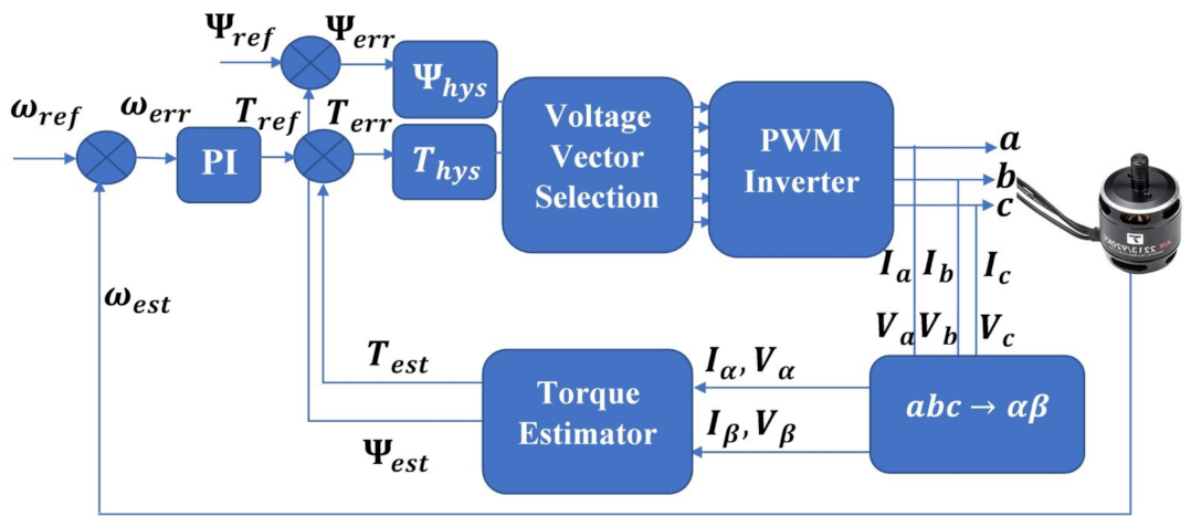
The DTC algorithm works by controlling the motor torque through controlling the angular position of the stator flux linkage in respect to rotor flux linkage. In DTC, the torque can be calculated as [
24]:
where
is the electromagnetic torque,
P is the number of magnetic poles,
and
are the respective stator and rotor flux linkage magnitudes and
is the angle between the stator and rotor flux linkage.
Correct operation of this control scheme is reliant on the accuracy of torque, speed and flux linkage estimation; the DTC algorithm establishes motor control by comparing these estimates to their set reference values. In particular, the errors in both torque and flux linkage are fed to hysteresis comparators, whose outputs are applied together with the position of the stator flux as inputs to a lookup table to select the appropriate voltage space vector. A full derivation of the DTC algorithm can be found in [
5].
2.2. Field-Oriented Control
To the best of authors’ knowledge, DTC is adopted in all commercial off-shelf UAV ESC due to implementation simplicity and hence, reduced cost of production [
25,
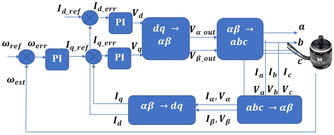
26]. A more complicated but inherently more accurate alternative is provided by field oriented control (FOC). The FOC algorithm maps the three phase motor currents into the two-phase domain (d-q) aligned with the rotor flux space vector via application of the Park transform. This allows the motor electromagnetic torque to be expressed as function of d-q domain quantities as [
27]:
where,
,
,
and
are the rotor flux and current components in the
d-
q domain, respectively. Control of d and q axis currents through proportional-integral (PI) controllers allows effective control of motor torque and flux:
where
is the proportional gain,
is the integral gain and
and
are the current errors for the
d and
q axis respectively.
This algorithm is underpinned by effective means of rotor position measurement, which is typically enabled by application of an optical encoder attached to the rotor shaft. Sensorless variants are also available, where the back-EMF is measured and used as the input to the control system. Unfortunately at low velocities, the back-EMF voltage is too small to measure and so open-loop control has to be used instead [
26].
3. Experimental Apparatus
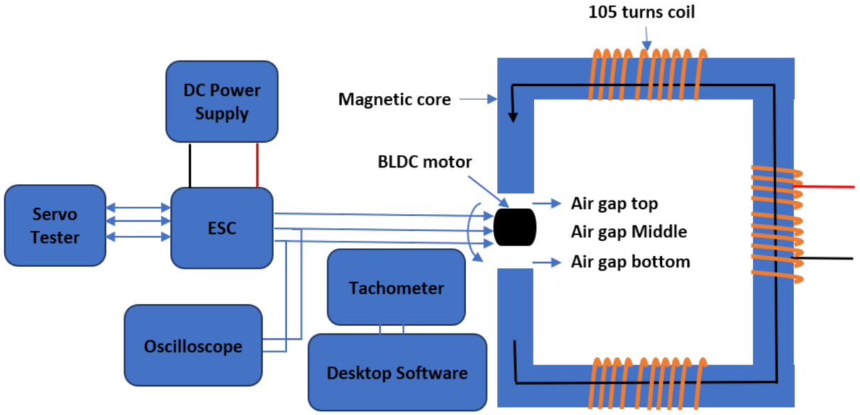
To enable the evaluation of external magnetic field impact on UAV propulsion motors operation testing in magnetic conditions representative of those encountered in the field a magnetic field test rig capable of producing variable magnetic field densities with a maximum magnitude of 0.2 T was developed [
5], a block diagram of which is shown in
Figure 1.
3.1. Magnetic Core Test Rig Design
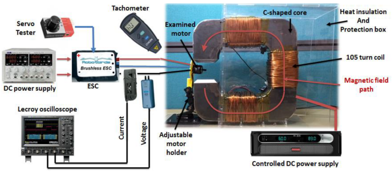
The test rig is composed of a C-shaped magnetic core, whose dimensions were calculated based on electromagnetic FEA simulation to generate the required magnetic field inside the air-gap, and emulate the magnetic field conditions inside the HVDC valve hall. The rig allows for inclusion of the tested propulsion motor architecture within its magnetic circuit and its examination under different desired magnetic field intensities. The magnetic field inside the core was varied using a controlled DC supply connected to the coils of the core. The core was kept inside an acrylic box for heat insulation, to isolate the heat generated in the coils from the motor under test as shown in
Figure 2.
The servo tester and DTC speed controller of BLDC motor are replaced with a Texas Instruments (TI) evaluation board DRV8303, which allows FOC control to be evaluated as well. The evaluation board is connected to a laptop and managed using TI InstaSpin Software Package.
Current magnitude flowing through the coil of the magnetic core ranges from 5 A up to 20 A, which is the maximum current produced by the DC supply. This magnitude is sufficient to induce magnetic field above 100 mT, which is the maximum magnetic flux induced inside a valve hall [
13].
Table 1 shows the simulated magnetic field density inside the air-gap of the magnetic core for different coil currents.
Further details about the development of the test rig can be found in [
5].
3.2. Propulsion System Test Components
Two commercial-off-the-shelf (COTS) UAV BLDC motors were used during the experiments; an Air Gear motor and a SwellPro motor. Both of these motors are sensorless and use the back-EMF to estimate the rotor position and speed.
Table 2 shows the motor characteristics.
3.3. Test Procedure
Each motor was mounted inside the core air-gap using the adjustable holder. The current, voltage and speed of each motor were measured in the presence and absence of different magnetic field magnitudes, where different motor speeds were examined using the servo tester.
4. Motor Magnetic Field Test Results
This section presents the results of experiments. The key parameters of interest were the motor current and speed for different duty cycles. The desired outcome was that the motor speeds increased with duty cycle, but did not change under the influence of the magnetic fields.
4.1. Air Gear Motor
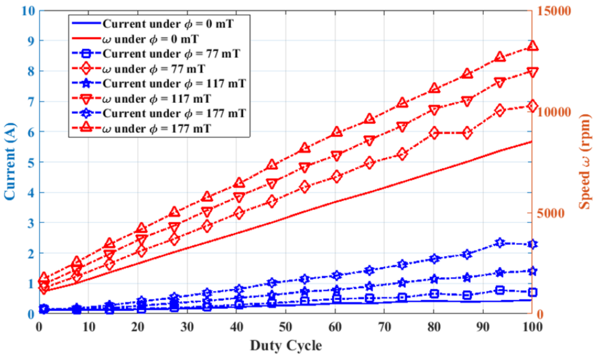
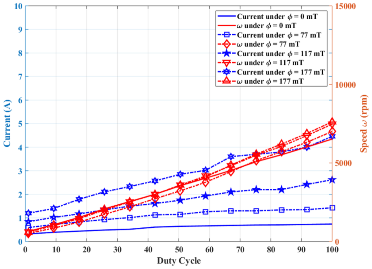
In
Figure 3, the root mean square (rms) current and the average rotation speed of the Air Gear BLDC motor are plotted against the control pulse width modulated (PWM) signal duty cycle. Both rms current and average rotation speed are mapped in the presence of different magnetic field densities. It can be seen that the DTC algorithm failed to compensate for the influence of the external magnetic flux.
Both the motor speed and current for a given duty cycle increased as the magnetic flux density increased. For example, at a duty cycle of 20%, the average rotation speed increased from 2540 rpm, in absence of external magnetic field, to 4190 rpm in the presence of external magnetic flux of 177 mT. The increase in the consumed current was from 0.143 A to 0.408 A, representing a 285% increase.
The increased current was less of a concern, as it only affected the operational flight time, however the increased motor speed could have a serious detrimental effects on the flight control systems, potentially causing the drone to crash.
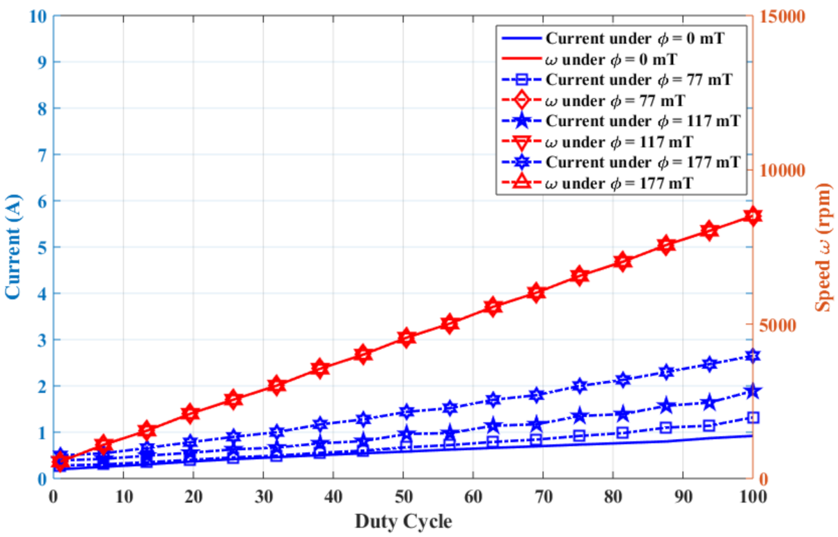
As discussed in
Section 2.2, the main advantage of the FOC algorithm is relying solely on the current and speed estimation rather than the angle between the rotor and stator flux linkage as in DTC algorithm, which impacts its performance in the presence of external magnetic flux. In
Figure 4, the rms consumed current and the average rotation speed of Air Gear BLDC motor are plotted against the control PWM control signal duty cycle, using FOC current control algorithm.
It can be seen that, whilst the current increased as the magnetic flux increased, the controller succeeded in sustaining the nominal rotation speed. The consumed current using FOC algorithm increased from 0.365 A to 0.783 A at 20% duty cycle for a magnetic flux of 177 mT, which was a 215% increase.
Though the overall current consumption of Air Gear motor using the FOC algorithm was higher than that consumed using DTC algorithm, the FOC algorithm showed significantly better performance in terms of maintaining a constant motor speed.
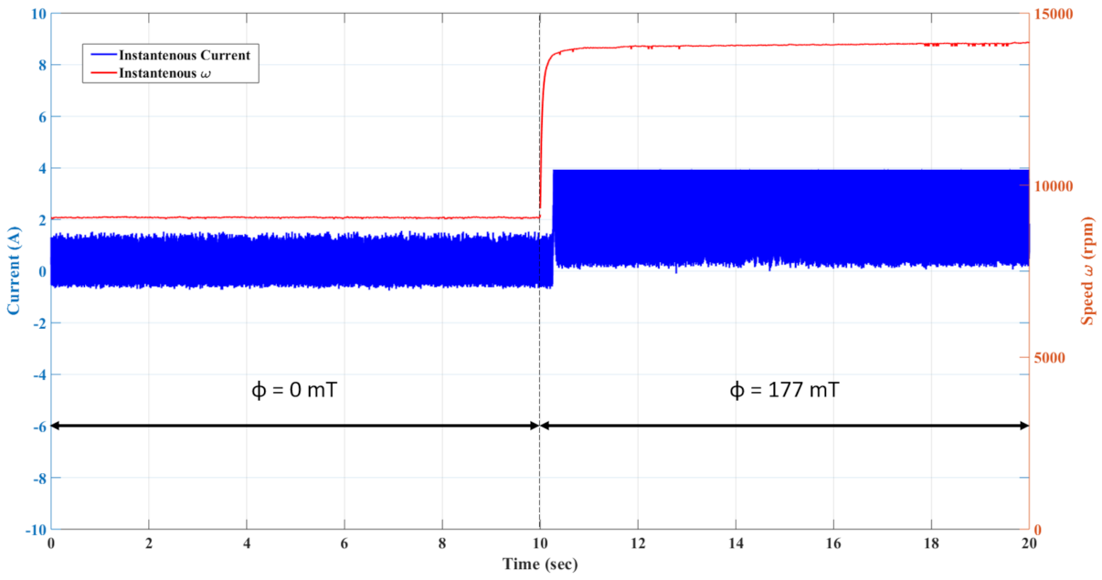
In
Figure 5, the instantaneous current and speed wave forms are shown for Air Gear motor at a target speed of 9070 rpm, in the presence and absence of external flux. At the instant of applying the external flux, the speed controller increased the peak-to-peak current from ∼2.1 A to ∼3.78 A and the speed began to increase from the value of 9050 rpm until it saturated at 14,050 rpm.
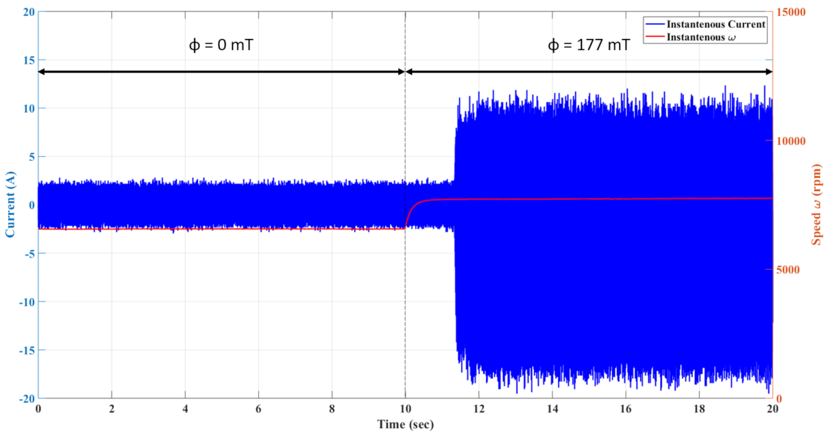
Figure 6 shows the corresponding plot for the Air Gear motor using the FOC algorithm. The motor showed a spike up to 10,177 rmp in the speed waveform at the instant of applying an external magnetic flux, however it settled back to the target speed after 640 ms. This shows that the FOC algorithm succeeded in recovering the motor nominal speed, however this was at the cost of increasing its peak-to-peak current from ∼7.3 A to ∼14.5 A.
4.2. SwellPro Motor
For the SwellPro BLDC motor, the rms consumed current and average speed are plotted against control signal duty cycle in
Figure 7 for the DTC algorithm. The SwellPro DTC speed controller, like Air Gear motor DTC speed controller, failed to sustain the rotation speed in presence of external magnetic flux. The relationship between the speed and magnetic flux was not as simple as for the Air Gear motor, as at low duty cycles, the speed actually decreased. At a 20% duty cycle, the speed decreased from 1800 rpm to 1477 rpm.
The performance of the speed control was improved by the use of the FOC algorithm, as shown in
Figure 8. It can be seen that the motor speed was held constant for all values of the magnetic flux, although the current did increase. As with the Air Gear motors, the FOC algorithm showed higher current consumption compared to the DTC algorithm for SwellPro motors.
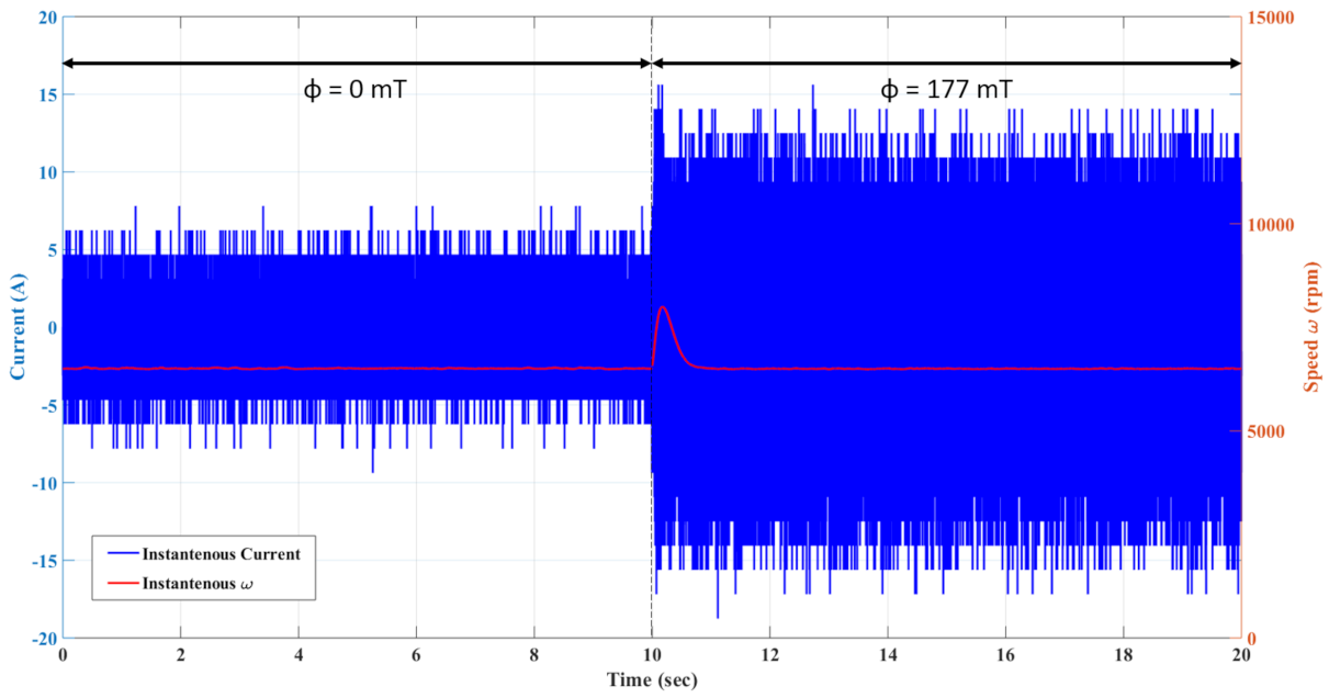
Figure 9 and
Figure 10 show the instantaneous current and speed wave forms for the SwellPro motors running the DTC and FOC algorithms respectively. The target speed was 6520 rpm and the magnetic flux was 177 mT.
For the DTC algorithm, the final motor speed was 7743 rpm, however the peak-to-peak current increased by ∼600% from ∼4.6 A to ∼28 A. For the FOC algorithm, the speed spike was 750 ms before it returns to the target. The current increased by ∼260% from ∼9.2 A to ∼24 A.
4.3. Analysis
Table 3 shows a comparison of the results for operation at a magnetic flux of 177 mT. The differences were relative to steady-state operation at 0 mT at 100% duty cycle. It can be seen that the FOC approach led to no steady-state error in the target rotational velocity, however the current consumption increased significantly. The DTC algorithm failed to track the set point velocity and there were velocity differences of up to 55%. Operation under a high magnetic flux was also observed to significantly increase the current draw as well.
Whilst the steady-state error of the FOC algorithm eventually reached 0, there is a transient period where the algorithm was adapting to the change in magnetic flux. This period ranged from 600 ms to 800 ms and during this time, there was an error in the motor velocity. This error would have to be dealt with by the higher-level UAV position or velocity flight control system to ensure the UAV didn’t crash. It is likely it would be considered as a disturbance to the higher-level controller.
To understand the reason behind these results, their structures need to be considered.
Figure 11 and
Figure 12 show the block diagrams of the DTC and FOC algorithms respectively. Both motors used in the experiments were sensorless and so the same back-EMF values were measured by the controllers at points ‘a’, ‘b’ and ‘c’.
The primary difference between the algorithms is that the FOC algorithm used a PI controller and Park transform block for the current control, rather than the hysteresis comparator used by the DTC algorithm for torque control. This appeared to significantly increase the robustness of the algorithm to the effects of the high magnetic field.
5. Conclusions
Inspection UAVs are a promising monitoring solution in the O&M of HVDC valve halls in offshore wind farms. The high magnetic fields, which could be found inside the facilities, could cause unwanted interference with the UAV propulsion system, specifically the BLDC motors.
Industrial wind farm operators are increasingly interested in the use of commercial-off-the-shelf (COTS) systems rather than more expensive bespoke robots. This paper has presented a systematic study of the effects of operating COTS UAV motors in the presence of high external magnetic fields.
It was found that the standard DTC algorithm which is widely used on COTS ESCs, could not operate effectively in the presence of high magnetic fields; the speed of the motors increased for a given duty cycle input as the magnetic flux increased. The increase in rotational velocity of the motors was as high as 55%. This would have a significant detrimental effect on the operation of the drone and would likely result in it crashing.
When the FOC algorithm was used however, it was found to be robust to the strength of the magnetic flux, at the cost of increased current consumption. After an initial velocity transient, the steady-state rotational velocity error was zero, however the current consumption increased by between 188% and 567%.
The current increase will have a significant impact on the operational flight time of the UAV. UAVs operating indoors can have flight times of 10–15 min. Operating in high external magnetic fields may reduce this to 2 or 3 min, which would make operations infeasible.
There are several areas of future work that will be investigated. Environmental characterisation will be key to the successful deployment of UAVs inside live HVDC substations. If the environment is saturated with a high magnetic field, then the use of UAVs using FOC will not be feasible. If the high magnetic fields are limited to specific areas or time periods (for example under fault conditions), then UAV flights may be feasible. Areas of high field strength could be treated as environmental obstacles in the same way that nuclear inspection robots treat radiation [
28].
From a low-level perspective, future work includes testing FOC performance at different orientation angles for BLDC motors with respect to direction of external magnetic flux, as well as control performance testing under conditions involving more complex time varying compositions of the external magnetic field. Furthermore, the impact of high external flux on the motor thermal operating conditions will also be examined.
Author Contributions
Conceptualization, M.H.; methodology, M.H., A.M., K.K. and P.T.; investigation, M.H., A.M. and J.M.; resources, K.K. and P.T.; data curation, M.H.; writing—original draft preparation, M.H.; writing—review and editing, S.W. and S.D.; supervision, S.W. and S.D.; project administration, S.W. and S.D.; funding acquisition, S.W. and S.D. All authors have read and agreed to the published version of the manuscript.
Funding
This research was supported by UK Research and Innovation through the Engineering and Physical Science Research Council (EPSRC) project HOME-Offshore (EP/P009743/1).
Institutional Review Board Statement
Not Applicable.
Informed Consent Statement
Not Applicable.
Data Availability Statement
The data presented in this study are available on request from the corresponding author.
Conflicts of Interest
The authors declare no conflict of interest.
Abbreviations
The following abbreviations are used in this manuscript:
| AC | Alternating Current |
| BLDC | Brushless Direct Current |
| COTS | Commercial-Off-The-Shelf |
| DC | Direct Current |
| DTC | Direct Torque Control |
| EMF | Electromotive Force |
| ESC | Electronic Speed Control |
| FEA | Finite Element Analysis |
| FOC | Field-Oriented Control |
| HVDC | High Voltage Direct Current |
| IGBT | Insulated Gate Bipolar Transistor |
| O&M | Operation and Maintenance |
| PI | Proportional-Integral |
| rms | root mean square |
| UAV | Unamnned Aerial Vehicle |
References
- Beerten, J.; Gomis-Bellmunt, O.; Guillaud, X.; Rimez, J.; van der Meer, A.; van Hertem, D. Modeling and Control of HVDC Grids: A Key Challenge for the Future Power System. In Proceedings of the 2014 Power Systems Computation Conference, Wroclaw, Poland, 18–22 August 2014; pp. 126–129. [Google Scholar]
- Röckmann, C.; Lagerveld, S.; Stavenuiter, J. Operation and Maintenance Costs of Offshore Wind Farms and Potential Multi-use Platforms in the Dutch North Sea. In Aquaculture Perspective of Multi-Use Sites in the Open Ocean: The Untapped Potential for Marine Resources in the Anthropocene; Buck, B.H., Langan, R., Eds.; Springer International Publishing: Cham, Switzerland, 2017; pp. 97–113. [Google Scholar]
- Lu, S.; Zhang, Y.; Su, J. Mobile robot for power substation inspection: A survey. IEEE/CAA J. Autom. Sin. 2017, 99, 830–847. [Google Scholar] [CrossRef]
- Heggo, M.; Kabbabe, K.; Peesapati, V.; Gardner, R.; Watson, S.; Crowther, B. Operation of Aerial Inspections Vehicles in HVDC Environments Part A: Evaluation and Mitigation of High Electrostatic Field Impact; Journal of Physics: Conference Series; IOP Publishing Ltd.: Bristol, UK, 2019; Volume 1356. [Google Scholar]
- Heggo, M.; Mohammed, A.; Melecio Ramirez, J.; Kabbabe, K.; Tuohy, P.; Watson, S.; Durovic, S. Operation of Aerial Inspections Vehicles in HVDC Environments Part B: Evaluation and Mitigation of Magnetic Field Impact; Journal of Physics: Conference Series; IOP Publishing Ltd.: Bristol, UK, 2019; Volume 1356. [Google Scholar]
- Van Hertem, D.; Gomis-Bellmunt, O.; Liang, J. HVDC Grids: For Offshore and Supergrid of the Future; IEEE Press Series on Power Engineering; Wiley: Hoboken, NJ, USA, 2016. [Google Scholar]
- Carmona Sanchez, J.; Watson, S. Robotic Inspection Vehicle for HVDC-VSC Facilities: Inspection of HVDC VSC Offshore Substations; University of Manchester: Manchester, UK, 2015. [Google Scholar]
- Marsh, C.; Barnes, M.; Crowther, B.; Watson, S.; Vilchis-Rodriguez, D.; Carmona Sanchez, J.; Shuttleworth, R.; Kabbabe, K.; Heggo, M.; Smith, A.; et al. Virtual reality interface for HVDC substation and DC breaker design and maintenance. In Proceedings of the 15th IET International Conference on AC and DC Power Transmission (ACDC 2019), Coventry, UK, 5–7 February 2019; pp. 1–6. [Google Scholar]
- Jodeyri, M.H.; Cao, J.Z.; Zhou, C.; Tang, G. Thyristor valve for the 12-pulse converter for the 3 Gorges—Shanghai II HVDC transmission scheme. In Proceedings of the 2010 International Conference on Power System Technology, Zhejiang, China, 24–28 October 2010. [Google Scholar] [CrossRef]
- Li, Y.; Ding, Q.; Li, K.; Valtchev, S.; Li, S.; Yin, L. A Survey of Electromagnetic Influence on UAVs from an EHV Power Converter Stations and Possible Countermeasures. Electronics 2021, 10, 701. [Google Scholar] [CrossRef]
- Mathisen, P.H.; Fossen, T.I. Robust Navigation System for UAVs in GNSS-and Magnetometer-Denied Environments. In Proceedings of the 2019 International Conference on Unmanned Aircraft Systems (ICUAS), Atlanta, GA, USA, 11–14 June 2019; pp. 1416–1424. [Google Scholar]
- Kher, M.S.; Bindu, S. Electromagnetic modelling of three phase UHVDC valve casing. In Proceedings of the 2013 Annual IEEE India Conference (INDICON), Mumbai, India, 13–15 December 2013. [Google Scholar] [CrossRef]
- Koers, F.M.; Landau, H.; Tap, G.E.; Juhlin, L.E.; Andersson, O.; Skansens, J. EMC considerations and planning for an offshore HVDC. In Proceedings of the 45th International Conference on Large High Voltage Electric Systems, London, UK, 24 August 2014. [Google Scholar]
- Wang, L.; Liu, F.; Xu, S.; Wang, Z.; Cheng, S.; Zhang, J. Design, Modeling and Control of a Biped Line-Walking Robot. Int. J. Adv. Robot. Syst. 2010, 7, 39–47. [Google Scholar] [CrossRef]
- Montambault, S.; Pouliot, N. Design and validation of a mobile robot for power line inspection and maintenance. In Field and Service Robotics; Springer: Berlin/Heidelberg, Germany, 2008. [Google Scholar] [CrossRef] [Green Version]
- Pouliot, N.; Richard, P.L.; Montambault, S. LineScout Technology Opens the Way to Robotic Inspection and Maintenance of High-Voltage Power Lines. IEEE Power Energy Technol. Syst. J. 2015. [Google Scholar] [CrossRef]
- Wang, S.; Yang, E.; Wang, X.; Deng, Q.; Liang, Q.; Mo, J. Development of a novel live-line inspection robot system for post insulators at 220-kV substations. Adv. Robot. 2010. [Google Scholar] [CrossRef]
- Zhang, H.; Su, B.; Song, H.; Xiong, W. Development and implement of an inspection robot for power substation. In Proceedings of the 2015 IEEE Intelligent Vehicles Symposium (IV), Seoul, Korea, 28 June–1 July 2015. [Google Scholar] [CrossRef]
- Zeng, J.; Wang, X.; Yang, J.; Wang, J.; Wen, H. Study on inspection robot for substation based on ultra-wide-band wireless localization system. In Proceedings of the 2015 IEEE International Conference on Information and Automation, Lijiang, China, 8–10 August 2015. [Google Scholar] [CrossRef]
- Qian, Y.; Wei, Y.; Kong, D.; Xu, H. Experimental investigation on motor noise reduction of Unmanned Aerial Vehicles. Appl. Acoust. 2021, 176, 107873. [Google Scholar] [CrossRef]
- Wang, C.M.; Wang, S.J.; Lin, S.K.; Lin, H.Y. A novel twelve-step sensorless drive scheme for a brushless DC motor. IEEE Trans. Magn. 2007, 43, 2555–2557. [Google Scholar] [CrossRef]
- Carey, K.D.; Zimmerman, N.; Ababei, C. Hybrid field oriented and direct torque control for sensorless BLDC motors used in aerial drones. IET Power Electron. 2019, 12, 438–449. [Google Scholar] [CrossRef] [Green Version]
- Sands, T. Control of DC Motors to Guide Unmanned Underwater Vehicles. Appl. Sci. 2021, 11, 2144. [Google Scholar] [CrossRef]
- Zhong, L.; Rahman, M.F.; Hu, W.Y.; Lim, K.W. Analysis of direct torque control in permanent magnet synchronous motor drives. IEEE Trans. Power Electron. 1997, 12, 528–536. [Google Scholar] [CrossRef]
- Koteich, M.; Le Moing, T.; Janot, A.; Defay, F. A real-time observer for UAV’s brushless motors. In Proceedings of the 2013 IEEE 11th International Workshop of Electronics, Control, Measurement, Signals and Their Application to Mechatronics, Toulouse, France, 24–26 June 2013. [Google Scholar] [CrossRef] [Green Version]
- Gamazo-Real, J.C.; Vázquez-Sánchez, E.; Gómez-Gil, J. Position and speed control of brushless dc motors using sensorless techniques and application trends. Sensors 2010, 10, 6901–6947. [Google Scholar] [CrossRef] [PubMed] [Green Version]
- Merzoug, M.S.; Naceri, F. Comparison of Field-Oriented Control and Direct Torque Control for Permanent Magnet Synchronous Motor (PMSM). World Acad. Sci. Eng. Technol. 2008, 45, 299–304. [Google Scholar]
- Groves, K.; Hernandez, E.; West, A.; Wright, T.; Lennox, B. Robotic Exploration of an Unknown Nuclear Environment Using Radiation Informed Autonomous Navigation. Robotics 2021, 10, 78. [Google Scholar] [CrossRef]
| Publisher’s Note: MDPI stays neutral with regard to jurisdictional claims in published maps and institutional affiliations. |
© 2021 by the authors. Licensee MDPI, Basel, Switzerland. This article is an open access article distributed under the terms and conditions of the Creative Commons Attribution (CC BY) license (https://creativecommons.org/licenses/by/4.0/).


 and
and 


