
Research of Target Detection and Classification Techniques Using Millimeter-Wave Radar and Vision Sensors


School of Information and Communication Engineering, University of Electronic Science and Technology of China, Chengdu 611731, China
*
Author to whom correspondence should be addressed.
Remote Sens. 2021, 13(6), 1064; https://0-doi-org.brum.beds.ac.uk/10.3390/rs13061064
Submission received: 29 January 2021
/
Revised: 8 March 2021
/
Accepted: 9 March 2021
/
Published: 11 March 2021
Abstract
:The development of autonomous vehicles and unmanned aerial vehicles has led to a current research focus on improving the environmental perception of automation equipment. The unmanned platform detects its surroundings and then makes a decision based on environmental information. The major challenge of environmental perception is to detect and classify objects precisely; thus, it is necessary to perform fusion of different heterogeneous data to achieve complementary advantages. In this paper, a robust object detection and classification algorithm based on millimeter-wave (MMW) radar and camera fusion is proposed. The corresponding regions of interest (ROIs) are accurately calculated from the approximate position of the target detected by radar and cameras. A joint classification network is used to extract micro-Doppler features from the time-frequency spectrum and texture features from images in the ROIs. A fusion dataset between radar and camera is established using a fusion data acquisition platform and includes intersections, highways, roads, and playgrounds in schools during the day and at night. The traditional radar signal algorithm, the Faster R-CNN model and our proposed fusion network model, called RCF-Faster R-CNN, are evaluated in this dataset. The experimental results indicate that the mAP(mean Average Precision) of our network is up to 89.42% more accurate than the traditional radar signal algorithm and up to 32.76% higher than Faster R-CNN, especially in the environment of low light and strong electromagnetic clutter.
1. Introduction
Autonomous cars [1], unmanned aerial vehicles [2], and intelligent robots [3] are usually equipped for target detection and target classification with a variety of sensors, such as cameras, radar (radio detection and ranging), laser radar, etc. [4]. In the past, the dominant approach was to obtain object recognition data using a single sensor. However, due to its own limitations, a single sensor cannot satisfy the requirements of all application scenarios [5,6].
There are three main tasks—three-dimensional shape classification, three-dimensional target detection and tracking, and three-dimensional point cloud segmentation—that depend on LiDAR, which has many advantages over other sensors, as can be seen in the comparison of different sensors and technologies in Table 1 [7,8]. Automakers generally replace LiDAR with frequency modulated continuous wave (FMCW) radar due to LiDAR’s high price. Millimeter-wave radar, which is a cheap and efficient sensor that has the distance and speed to produce robust performance and good estimation precision in all weather conditions, is widely used in the automotive industry and traffic monitoring fields. However, it has disadvantages, such as weak azimuth measurement, missed and false detection of targets, and the serious influence of electromagnetic clutter [6,9]. In addition, the camera can capture high resolution images only under good lighting and no-fog conditions [10,11,12]. Therefore, it is necessary to fuse different sensors to solve a specific task, especially target detection and classification.
In the past years, many sensor fusion methods have been proposed for autonomous driving applications [13,14,15,16]. In addition, [17,18,19,20,21] examine the existing problems of the current sensor fusion algorithm. According to different data processing methods, sensor fusion can be divided into three levels: the data layer, feature layer and decision layer.
The main idea behind the data layer fusion method [22,23] is to extract image patches according to regions of interest (ROIs), generated by radar points in camera coordinates. [24] proposes a spatial calibration method based on a multi-sensor system, which utilizes rotation and translation of the coordinate system. Through comparison with the calibration data, the validity of the proposed method is verified. In the fusion of millimeter-wave radar and camera, the data level fusion effect is not ideal because of the great difference between sensor data and the high requirement of communication ability [25,26]. In [27], a new method for multi-sensor data fusion algorithms in complex automotive sensor networks is proposed, and a real-time framework is introduced to test the performance of the fusion algorithm using hardware-in-the-loop (HIL) co-simulation at the electronic system level. A robust target detection algorithm based on the fusion of millimeter-wave radar and camera is proposed in [28]. First, the image taken by the camera on foggy days with low visibility is defogged. Then, the effective target filtered by millimeter-wave radar is mapped to the image plane. Finally, the weighted method is used to fuse the camera visual network identification results with the radar target estimation results to obtain the final ROI results. Simulation results show that the accuracy of millimeter-wave radar and camera fusion is obviously better than that of a single sensor.
Feature-level fusion is a fusion method that has become popular recently [7,29,30]. In this scheme, radar points, which stored in the form of pixel values [31], are converted to a two-dimensional image plane from the three-dimensional world. In order to improve the accuracy of target detection, the author proposed a Camera Radar Fusion-Net (CRF-NET) in [32] to fuse the data from cameras and radar sensors of road vehicles, which opens up a new direction for radar data fusion research. In this study, experimental results show that the fusion of radar and camera data in the neural network can improve the detection score of the most advanced target detection network. The authors of [30,33] propose a new radar-camera sensor fusion framework for accurate target detection and range estimation in autonomous driving scenarios. The 3D proposals generated by a radar target proposal network are mapped to images and used as the input of the radar proposal network. Although the saved computational resources are based on millimeter-wave (MMW) radar information and camera data, this method cannot detect obstacles. [34] proposes a new spatial attention fusion (SAF) method based on MMW radar and visual sensors that focus on the sparsity of radar points. This method is applied to the feature extraction stage, which effectively utilizes the features of MMW radar and visual sensors [35]. Different from splicing fusion and element addition fusion, an attention weight matrix is generated to fuse visual features in this method.
The last fusion scheme is implemented at the decision level, which combines the prediction results of radar and vision sensors to generate the final result. It requires each sensor to calculate the position, speed and contour of the target according to its own detection information and then performs fusion according to the target information [36]. In the pioneering work of [37], Jovanoska extracted the distance and radial velocity of the target through multiple sensors and performed data fusion to improve the tracking accuracy. However, the complexity of the algorithm was increased due to the association ambiguity. In [38], the extended Kalman filter algorithm is used to track targets based on positive information sensed by sensors. It proposes a new target tracking method based on deep neural network–long-short term memory (DNN-LSTM), which is based on high level radar and camera data fusion in [39]. First, the target detected by the camera is identified, and a bounding box is generated. The trained DNN is then used to predict the position of the target using the bounding box. Finally, the location detected by the asynchronous camera and radar is correlated and fused using timestamps in the decision box.
In an unmanned sensing system, sensor fusion is an important method to improve target detection and classification, but the information fusion between multiple sensors is incomplete due to the different capabilities of different sensors. With the development of deep learning, there is high-precision target classification using visual sensors [40,41]. Therefore, the credibility and effectiveness of target classification cannot be guaranteed in the case of camera failure. In order to solve this problem, more and more researchers have begun to explore the potential of millimeter-wave radar in the field of target classification and achieving target classification and action recognition based on micro-Doppler signals [42,43,44]. In [45], four classification tasks, including subject classification, human activity classification, personnel counting and rough location, were completed by using micro-Doppler features. This study provides valuable guidance for the model optimization and experimental setting of basic research and application of the micro-Doppler. [46] proposes a new method for human motion classification using synthetic radar micro-Doppler features, which are evaluated through visual interpretation, kinematic consistency analysis, data diversity, potential spatial dimensions and significance mapping. In [47], an extended adversarial learning method is proposed to generate synthetic radar micro-Doppler [48,49] signals adapted to different environments to solve the problem of a lack of a millimeter-wave radar fretting feature dataset.
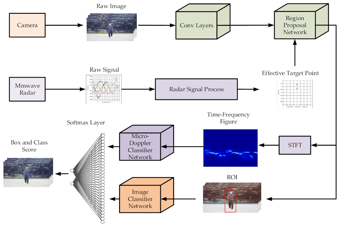
In this paper, we introduce a target detection and classification method based on millimeter-wave radar and camera sensor information fusion. Because the radar proposal network is dependent on the micro-Doppler effect and convolution module, the radar network is called MDRCNN (micro-Doppler radar CNN) and the proposed fusion network model is called RCF-Faster (Radar Camera Fusion-Faster) R-CNN. Based on the Faster R-CNN framework [50], targets detected by the radar are mapped to the image space by adopting the method of radar space mapping. In order to utilize the radar information, it is necessary to map the radar-based physical-spatial information to the center of the corresponding target in the image, which requires the accurate correlation between the target information detected by the radar and the camera at the scene. We creatively propose a target classification method, based on radar micro-Doppler features and image features through short-time Fourier, transforming effectively the target radar data to the frequency spectrum. CNN (Convolutional Neural Network) is used as the radar feature extraction network, and the target image features are extracted by the clipped CNN, which redesigned the SoftMax layer to correlate between radar features and image features. In order to solve the performance problem of existing methods, which are limited by image recognition capabilities, our fusion method is proposed. The proposed method depends on image recognition and the micro-Doppler effect of radar signals as radar features to identify target classes.
In this study, we evaluate the performance of the traditional radar processing algorithm, the Faster R-CNN network, and our proposed method for target detection and classification in different environments. This study also critically evaluates the actual testing of the proposed solution and discusses future requirements to address some of the challenges required in the actual application. The rest of this paper is organized as follows: Section 2 introduces the network framework and algorithm details of radar and camera fusion proposed in this paper. Section 3 introduces the experimental test and verification, based on MR3003 mm wave radar and Hikvision camera. Section 4 analyzes and summarizes the performance of the proposed algorithm and the measured results. Section 5 is the conclusion of this paper.
2. Methodology
2.1. Radar and Camera Fusion Structure
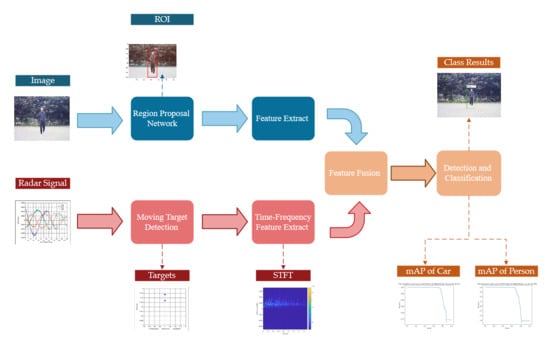
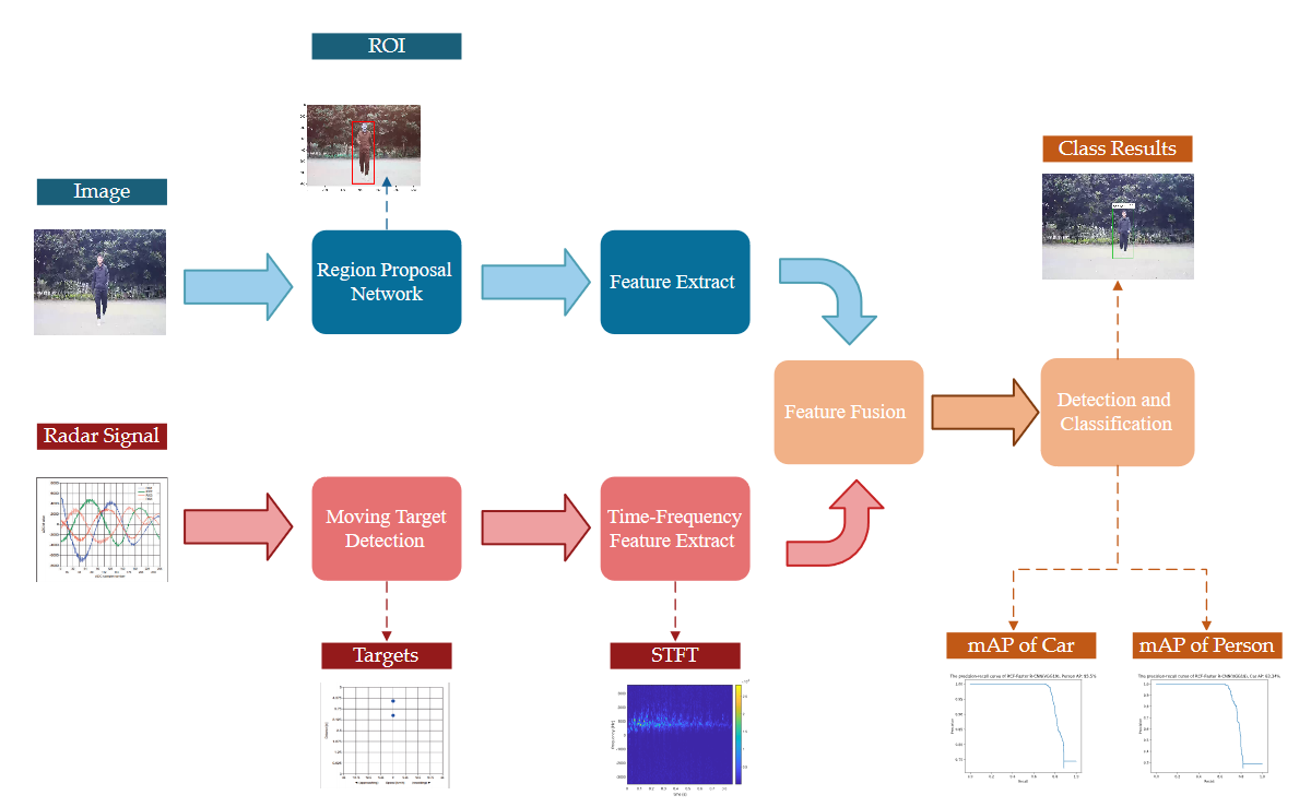
In this section, we will introduce a target detection and classification method of millimeter-wave radar and camera sensor information fusion. The framework for the proposed fusion network design in this paper is shown in Figure 1. The points of radar are transformed to image plane by spatial calibration and associate with target detection boxes obtained through the Region Proposal Network (RPN). This method considers the advantages of both radar and image, increasing the precision and reliability of object detection.
We propose a target classification method based on radar micro-Doppler features and image features. The short-time Fourier transform (STFT) is applied to radar data of effective targets to obtain time-frequency spectrum, then radar features are extracted from time frequency spectrum using CNN. The target image features are extracted from cropped CNN, using SoftMax layer for association. In Section 2.2, we introduce the process of radar signal preprocessing. In Section 2.3, we describe the mapping algorithm for the space-time alignment of radar data and image data. In Section 2.4.1, we propose a target detection algorithm based on information fusion. Finally, we propose a target classification algorithm based on micro-Doppler features and image features, which is detailed in Section 2.4.2.
2.2. Radar Data Preprocessing
In this paper, frequency modulated continuous wave (FMCW) radar is used as the signal data acquisition equipment. The equipment can measure the distance and speed of the target, which can accurately reflect the physical state of the environment. Due to the large difference between radar signals and images in data format, it is difficult to perform fusion at the data level. Therefore, it is necessary to preprocess radar signals; the processing block diagram is shown in Figure 2. Radar data preprocessing includes three FFT modules and a Constant False Alarm Rate (CFAR) module. The units of moving targets were detected by CFAR. Through 1-D FFT, 2-D FFT and 3-D FFT processing, the speed, distance and azimuth of the moving target are obtained.
According to the echo characteristics of FMCW radar, the original radar data was re-arranged, as shown in Figure 3. The millimeter-wave radar echo points used in this study are 32,768; the number of wave points for each FM period is 256, and there are 128 cycles per frame. To be consistent with the radar system, the parameters of 1-D FFT and 2-D FFT are set to 256 and 128, respectively.
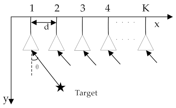
The uniform isometric antenna array structure of k antennas of millimeter-wave radar is shown in Figure 4. Among the array antennas, the distance between the antennas is d, and the angle between the target and the antenna is θ. represents the frequency domain data of the PRI echo and the range cell. Through 1-D FFT and 2-D FFT processing, the two dimensional range-Doppler spectrum was transformed. Then the units of moving targets were detected by CFAR (Constant False Alarm Rate). Finally, the azimuth information of the point target was obtained by FFT processing of k antennas.
CFAR detection is a signal processing algorithm that provides detection threshold value and minimizes the influence of clutter and interference on the false alarm probability of the radar system. The block diagram of the principle is shown in Figure 5. We adopted the two-dimensional CA-CFAR (Cell Avearege-Constant False Alarm Rate) method, and the specific process is as follows:
- 1.
- Select reference units for the signal data after two-dimensional FFT, and estimate the noise background in the range dimension and Doppler dimension.
- 2.
- A protective window is set to increase the detection accuracy, as the background is relatively complex. The detection threshold equation is as follows, where the detection unit is , the protection window is a rectangular window of , and μ is the threshold factor.
- 3.
- The detection threshold is compared with the average estimated noise value of the two-dimensional reference unit area. If the detection statistics of the unit to be detected exceed the threshold value determined by the false alarm probability, the detection unit is judged to have a target of
2.3. Radar and Vision Alignment
In this paper, we establish an integration perception platform coordinate system whose origin is the midpoint of the connection between the camera and the millimeter-wave radar, which are placed on the same vertical plane, making the viewing angle of the sensors consistent. The spatial detection relationship between the radar, the camera and the coordinate system of the fusion platform is shown in Figure 6.
The internal and external parameters of the camera are accurately obtained through the camera calibration toolbox. Due to the complexity of the outdoor environment and the spatial position relationship between the millimeter-wave radar and the camera equipment, this paper adopts a simple method to realize the mapping transformation between the radar and the visual system. The specific method steps are as follows, where is the target in the world coordinate system.
- 1.
- The offset vector of the radar relative to the world coordinate system is , and the transform equation between the polar coordinate system of the radar coordinate system and the three-dimensional world coordinate system is such that is the radial distance between the millimeter-wave radar and the target and is the azimuth angle between the radar and the target.
- 2.
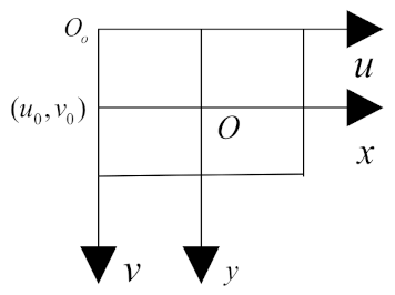
- The camera imaging projects the three-dimensional objects of the world onto a two-dimensional pixel image through the camera lens. The image coordinate system is generated by the image plane into which the camera projects the world coordinate points. The center point of the image physical coordinate system is the intersection point of the optical axis and the plane, the origin pixel point of the pixel coordinate system of the image and origin point of camera coordinate system, as shown in Figure 7.
- 3.
- The transform relationship between pixel coordinate system and camera coordinate system, between camera coordinate system and world coordinate system, and between world coordinate system and image pixel coordinate system are shown as follows, where and are the physical size of each pixel of the image in and direction, respectively, is the focal length of the camera imaging, is the orthogonal unit matrix, is offset vector of the camera relative to the world coordinate system, is the camera internal parameter matrix and is the camera external parameter matrix.
2.4. Network Fusion Architecture
Due to the existing radar and camera integration framework, the target classification module is determined mainly by the image features, which are affected by light intensity and weather changes. Therefore, we put forward a new fusion framework based on millimeter-wave radar and cameras, called Fusion RPN-CNN. First, we extract the target candidate box in the image with RPN, and then we associate it with radar space mapping ROI as input of a classification of network information. Finally, by extracting the micro- Doppler features of the target, the redesigned CNN network takes the time-frequency spectrum and the ROI of the image as the input and two-dimensional regression of the target boundary box coordinates and classification fraction of boundary box as the output. SoftMax Loss and Smooth L1 Loss are used for network joint training to obtain classification probability and bounding box regression.
2.4.1. Fusion Object Detection
In this paper, the ROIs generated from the target results detected by milli-meter-wave radar are mapped to the image pixel coordinates system, and the region changes dynamically with the distance between the target and the radar device. An improved object detection algorithm is proposed to obtain the consistency detection results of targets in the ROI region detected by vision and radar through IOU(Intersection over union).
In the same image, the coincidence degree of the area detected by the camera and the area detected by the radar is calculated to realize the correlation and correction of the target detection box. The calculation formula of coincidence degree is as follows, where is the real detection box of the target on the image, represents the coincidence area of the detection box obtained by the camera and the detection box obtained by the millimeter-wave radar projection, and represents the coincidence degree of the proportion of the coincidence area in the accurate detection area of the target.
This is example of the equation:
After setting the coincidence threshold, the correlation results are as follows, where is the correlation function of the target detection box. If the correlation is greater than the coincidence threshold, it means the correlation is successful, and if the correlation is less than the coincidence threshold, it means the correlation fails.
2.4.2. Fusion Object Classifier
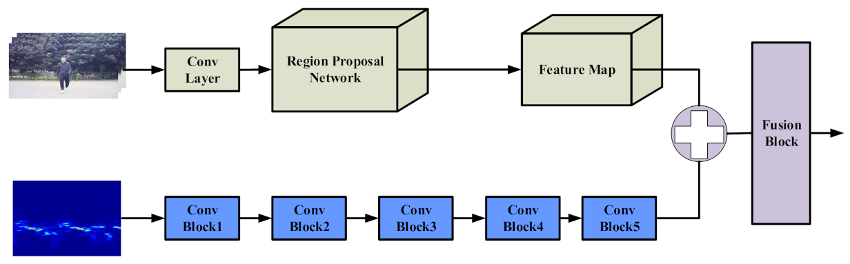
Based on the structure of the CNN classifier, we designed a target classifier to extract time-frequency graph features and image features. The model consists of two branches: time-frequency processing and image processing. Considering the large difference between the time spectrum graph and the image data, two input channels are set as and respectively, in this fusion network, and a parallel network is established for feature extraction. The fusion block takes ROIs and the feature map of the image channel and the feature vector of the radar channel as input, and outputs classification score and bounding box logistic regression.
The specific structure is shown in Figure 8.
The traditional time-frequency analysis method is based mainly on parameter analysis to extract target features and information, which cannot make full use of the features of time-spectrum images. Inspired by the advantages of the VGG16 [51] network in image classification, with a small amount of computation and high precision, the designed network consists of five convolution blocks, which transform radar inputs to feature vectors. The radar feature vectors and image feature maps, which are extracted by RPN and Conv Layer, are added into the fusion block.
The framework of the fusion block is shown in Figure 9. In the fusion block, fusion features are processed by the FC (full connect) layer to obtain fully connected feature vectors. The target boxes are obtained through linear regression of the feature vector. In addition, classification scores are calculated using the fully connected feature vector and the SoftMax Loss function.
3. Results
3.1. Dataset Establishment
3.1.1. Equipment
Due to limitations of existing public datasets such as KITTI, nuScences and Oxford RobotCar, which only include target speed, distance, and RCS information and lack original target echo and micro-Doppler features, we built a fusion data acquisition platform, based on the Mr3003 radar transceiver and DS-IPC-B12V2-I Hikvision webcam, to set up a time and space synchronization dataset. The effectiveness of the algorithm proposed in this paper is verified based on the fusion dataset.
MR3003 is a high-performance, automotive qualified, single-chip 76–81 GHz transceiver for radar applications. The MR3003 transceiver includes three transmitting and four receiving channels. The MR3003 provides best-in-class performance, including high angular resolution with TX phase rotation, best-in-class separation of objects due to low phase noise and linearity, and long detection range due to high output power and low noise figures. The parametes of MR3003 radar is shown in Table 2. The Hikvision webcam DS-IPC-B12V2-I is suitable for outdoor image acquisition under different scenes; the highest resolution can reach 1920 × 1080 @ 25 fps. The main parameters of the DS-IPC-B12V2-I camera is shown in Table 3.
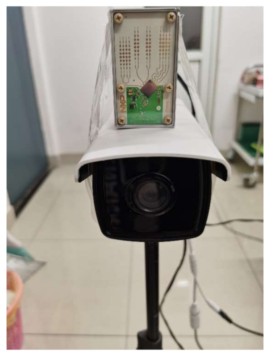
We set up the fusion acquisition platform of the millimeter-wave radar and camera as shown in Figure 10. The camera bracket is used to install the Hikvision camera, and the MR3003 radar is fixed directly above the camera to establish the world coordinate system, the radar viewing angle coordinate system and the camera viewing angle coordinate system. The translation matrix of the radar relative to the camera is .
3.1.2. Dataset Structure
In different measured scenes, including intersections, highways, roads and playgrounds in schools, we collected a large number of spatial-temporal synchronized images and radar signal fusion data in the daytime and at night. In order to enrich the data structure of the dataset, we enhanced the dataset in VOC standard format. The specific composition of the dataset is shown in Table 4 and Table 5, and some of the measured scenes are shown in Figure 11.
Based on the data in Table 4 and Table 5, our dataset includes 3385 training samples, 1451 validation samples and 1209 test samples. In addition, there are 4188 pedestrian targets and 1857 vehicles. According to working conditions of the millimeter-wave radar and camera, there are 1617 samples with the camera disabled and 348 samples with the radar disabled.
3.2. Joint Calibration Experiment
In this section, according to the proposed sensor joint calibration algorithm, the camera’s internal matrix is calculated by the MATLAB camera calibration toolbox. The specific parameters are shown in Equation (11).
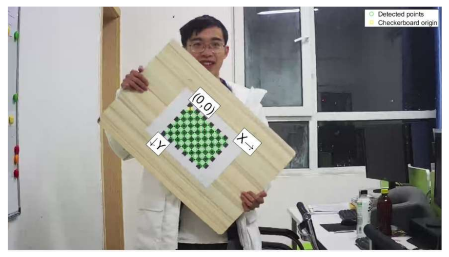
The checkpoints of an image are shown in Figure 12. The checkerboard origin is ; most of points are correctly detected in this image.
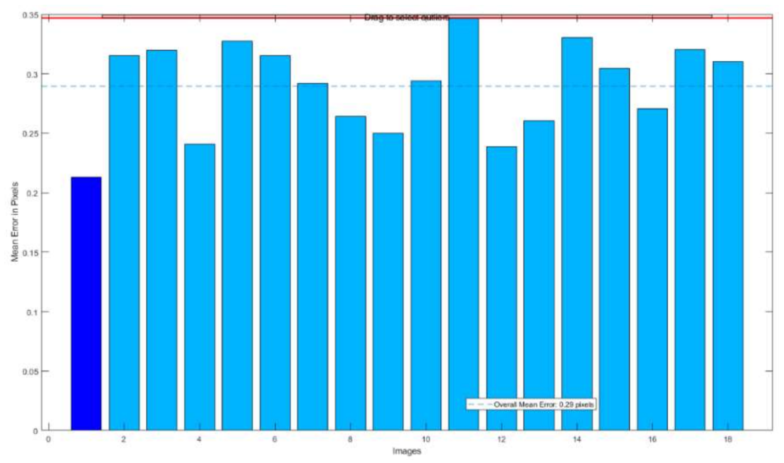
The reprojection error is shown in Figure 13. In camera calibration results of 13 images, the average reprojection error is between 0.25~0.3, within a reasonable range. It proves the effectiveness of the camera calibration.
According to the relationship between radar points of different distances and anchors in the image plane, the linear model is used to perform radar mapping points in the picture. Some results are shown in Figure 14. In this figure, the blue box represents the area after radar mapping and the green box is the ground truth area.
3.3. Radar Time-Frequency Transform
In this section, the feature information in the time spectrum diagram is extracted to classify the targets. The data used in the experiment are all radar signals collected by fusion in the measured dataset. The time spectrum diagram is generated by short-time Fourier transform.
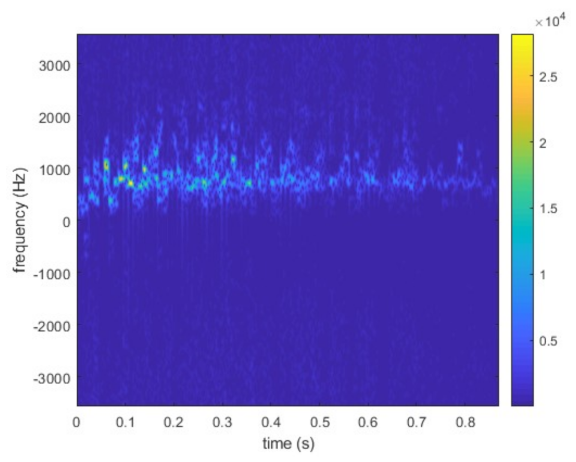
The parameter of the micro-Doppler signatures spectrum is shown in Figure 15. The frequency time spectrum is transformed by the STFT method, with a sampling frequency of 7114 Hz and an energy amplitude of . In order to input for MDRCNN, the time-frequency signal is normalized to set the energy range to 0~255. The scale is from to .
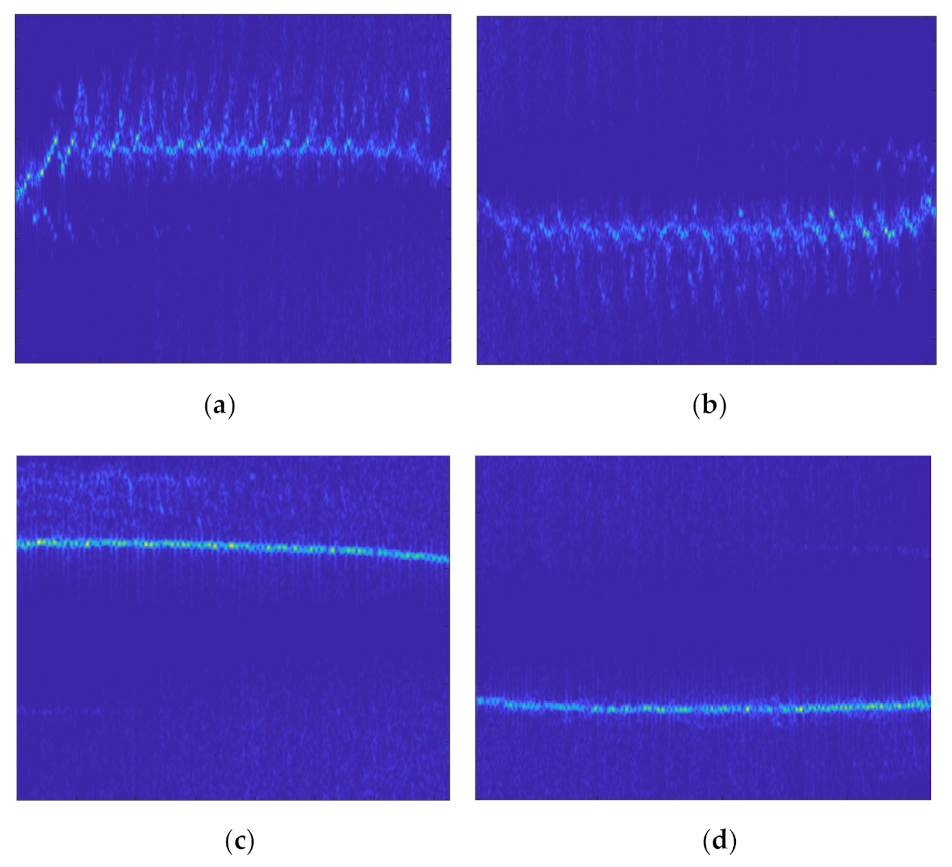
Some of the transformation results are shown in Figure 16. Figure (a) and (b) represent people running and walking. Figure (c) and (d) show the movement of a vehicle. Because of the great difference of the target features in the figure, the micro-Doppler feature is effective as the feature of the target classification.
3.4. Results of Target Detection and Classification
To evaluate the effectiveness of designed RCF-Faster R-CNN, we trained different target detection and classification models based on camera, radar or multiple sensors and made predictions on the fusion dataset. Based on the method mentioned in [1,36,45], the radar detection results were used as input for the classification network to assist the proposal areas of the RPN. The state-of-the-art fusion model mentioned in the citation is called Radar&Faster R-CNN in this paper. The RCF-Faster R-CNN, Radar&Faster R-CNN, Faster R-CNN and traditional signal algorithm are compared in this section. The training configurations and implementation details of our model are the same as Faster R-CNN. According to extensive training results, the SGD (Stochastic Gradient Descent) is set as the optimizer, whose learning rate is and momentum is 0.9.
In order to make the different network model training better, the training dataset is used in the feature learning stage. Validation sets are mainly used for post-training evaluation, and the sensor failure data in the validation set is less than that in the test set. However, the experimental data of CFAR is based on all the data, and the main purpose is to select a better threshold value. In this experiment, we set different threshold values in CFAR detection as a comparison with our algorithm. The results of target detection based on radar are shown in Table 6.
Because the traditional radar algorithm cannot identify the target, only precision rate and recall rate are calculated. However, the whole post-training network models are used to detect the target and determine the classes of object. Precision-recall (P-R) curves of Faster R-CNN, Radar&Faster R-CNN and RCF-Faster R-CNN models are shown in Figure 17 and Figure 18.
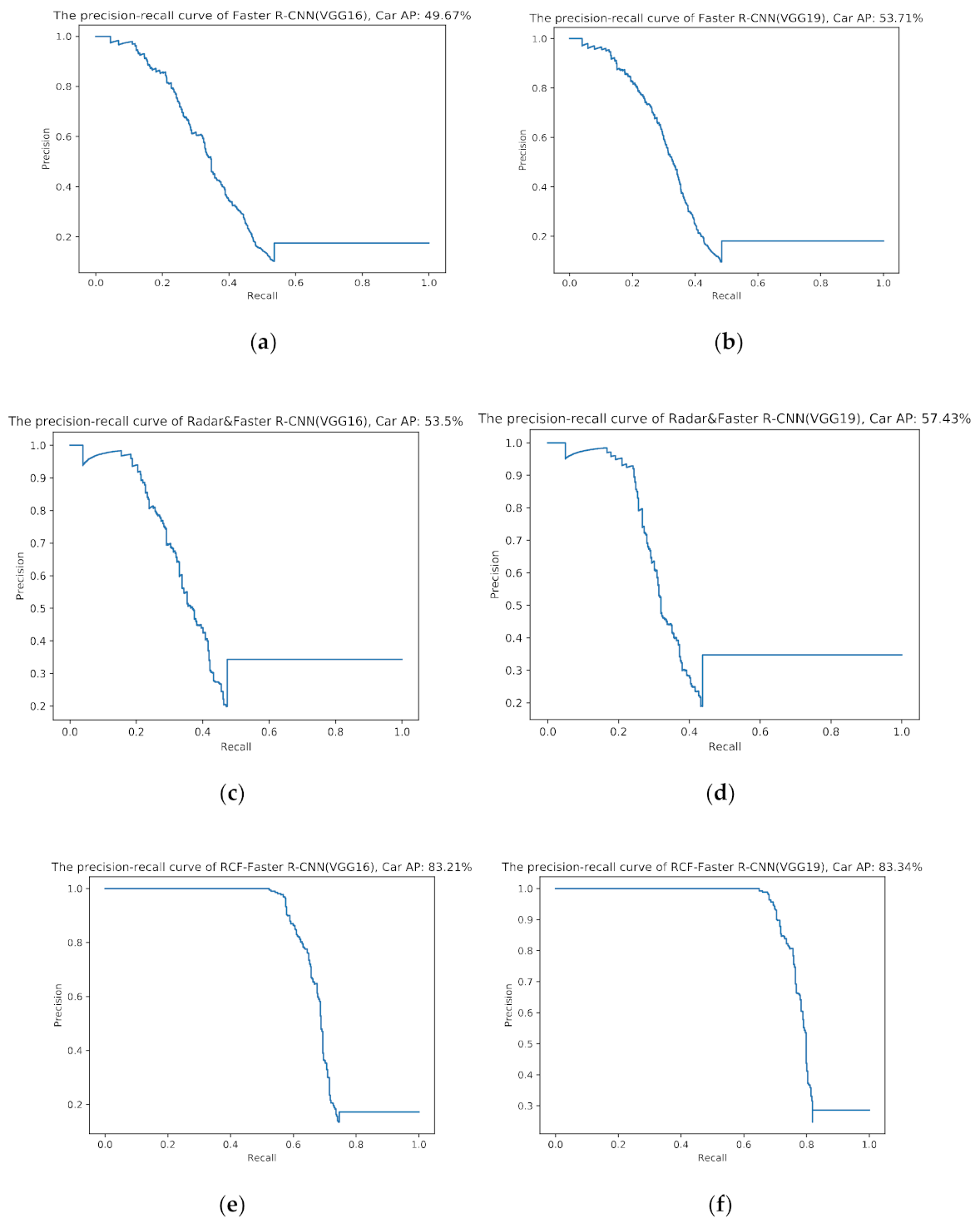
Figure 17 shows the AP of a car based on six models: Faster R-CNN(VGG16), Faster R-CNN(VGG19), Radar&Faster R-CNN(VGG16), Radar&Faster R-CNN(VGG19), RCF-Faster R-CNN(VGG16) and RCF-Faster R-CNN(VGG19). The result of the classifier based on Radar&Faster R-CNN is 3.83% higher than based on Faster R-CNN and 29.71% lower than based on RCF-Faster R-CNN. In addition, the result of the classifier based on VGG16 is 1~4% lower than based on VGG19. In conclusion, the performance of RCF-Faster R-CNN is better than Faster R-CNN and Radar&Faster R-CNN in vehicle recognition. The main reason is that it is difficult to identify vehicles with light interference in the nighttime picture. However, the micro-Doppler feature as a classification basis is unaffected by light.
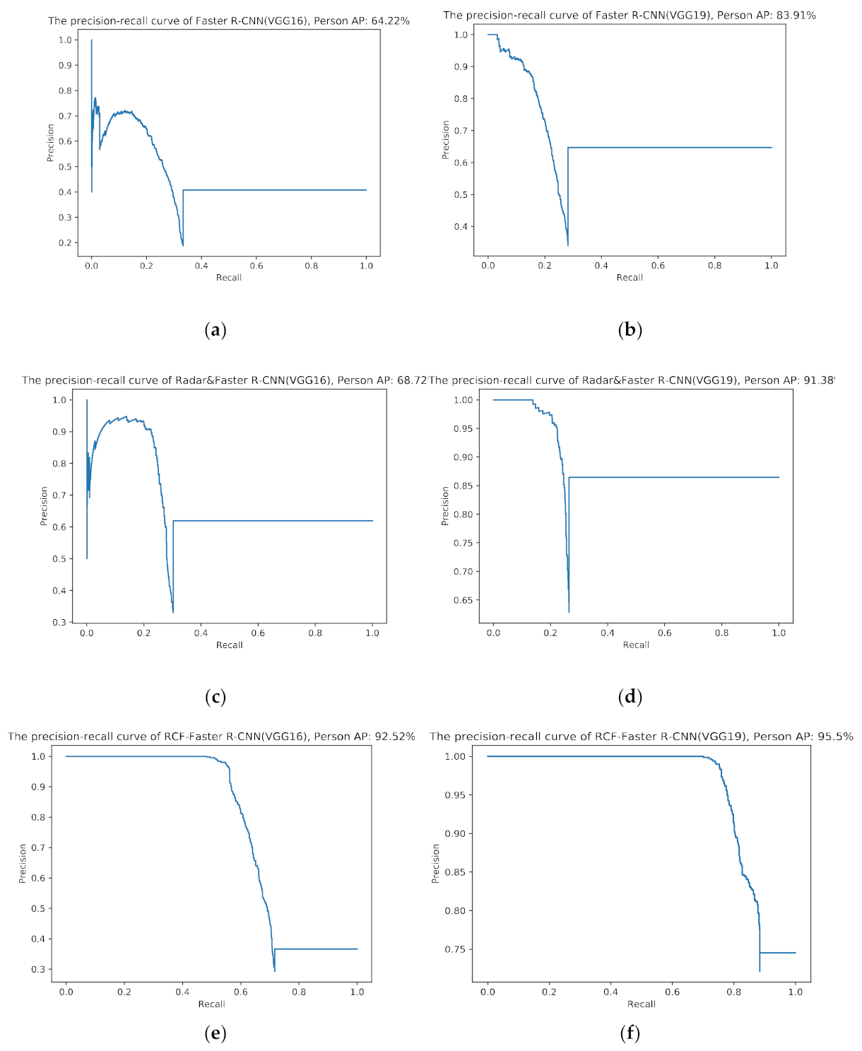
The P-R curve of a person is shown in Figure 18. Because the pedestrian movement scene is relatively simple, the recognition accuracy of all models is higher than that for vehicles. However, there are many pictures of almost no-light scenes. The result of the classifier based on RCF-Faster R-CNN is 39.89% higher than based on Faster R-CNN and 27.92% higher than based on Radar&Faster R-CNN on average.
The experiments were designed to compare the classification performance of RCF-Faster R-CNN and Faster R-CNN, where VGG-16 and VGG-19 [51] are used, respectively, in the classifier for exploring the influence of the network structure. In Table 7 and Table 8, trained models are evaluated in the fusion dataset under multiple evaluation criteria, such as AP50, AP75 and AP100.
According to Table 7 and Table 8, the mAP of a person is up to 64%~95% and of a car is only 49%~83%. In addition, the result of the classifier based on VGG16 is 2~15% lower than based on VGG19, which explains the influence of the network structure and training strategy. In addition, the AP and the mAP of the trained models decreases from 56.95%~89.45% to 44.69%~77.45% under the condition of AP50, AP75 and AP100. On the whole, RCF-Faster R-CNN is superior to Radar&Faster R-CNN, and because of the fusion of radar detection areas, Radar&Faster R-CNN is slightly better than Faster R-CNN.
4. Discussion
An autonomous environment perception system may ultimately resolve the disagreement between reliability and practicability on the condition that the multiple-modality information can be effectively fused. In contrast to exiting fusion strategies, the micro-Doppler feature extracted from radar is applied to target classification. Our method makes full use of radar-based information and resolves the problem of classification using image information that ensures the agreement between radar and camera in the process of fusion. As Table 4 and Table 5 show, we established a radar-camera-based fusion dataset of 6045 samples (4188 pedestrians, 1857 vehicles, 1617 with camera disabled and 348 with radar disabled), including intersections, highways, roads, and playgrounds in schools, during the day and at night. The reprojection error, based on 18 pictures filmed by a Hikvision webcam DS-IPC-B12V2-I, is between 0.2 and 0.3, calculated by the camera calibration toolbox. The results of radar mapping indicate that there is an error between the ground truth target and mapping point due to the lack of height information. For higher accuracy of detection, the radar points are used to scale and transform into 16 scale boxes. In our fusion framework, the time-frequency spectrum of a person and car include different velocity, direction and amounts. The detection precision is 94.58%, and the recall is 66.71%, based on a threshold value of and using CFAR algorithm of radar. If the threshold value is set as , the detection precision decreases by 13.56% and recall increases by 24.06%. The P-R curves of a car and person for Faster R-CNN, Radar&Faster R-CNN and RCF-Faster R-CNN are calculated as shown in Figure 17 and Figure 18. The performance of RCF-Faster R-CNN is higher than that of Faster R-CNN and Radar&Faster R-CNN. Through the analysis of the data in Table 7, the reason why the AP of a car is worse than that of a person is likely due to the fact that there are more samples of persons than cars, and the environment of cars is more complex than persons, which leads to the difficulty of model training. Therefore, the AP of a person is up to 64%~95%, and the AP of a car is only 49%~83%. In addition, the results of the classifier based on VGG16 are 2~15% lower than based on VGG19, which explains the influence of the network structure and training strategy. The results of the training model based on AP50 are on average 4.8% higher than those based on AP75 and 6.7% higher than those based on AP100. The mAP of Faster R-CNN based on VGG19 under AP75 is 10.39% different from that under AP100. The mAP of RCF-Faster R-CNN and Radar&Faster R-CNN under the conditions of AP50 and AP75 differs by 4%~5%. In the case of standard AP75 and AP100, the average mAP of Faster R-CNN, Radar&Faster R-CNN and RCF-Faster R-CNN differ respectively by 8.55%, 3.25% and 8.31%. After analyzing the experimental results, RCF-Faster R-CNN has the best stability under different evaluation criteria, while Radar&Faster R-CNN has the best performance. The AP of a car for the classifier based on Radar&Faster R-CNN(VGG16) is 3.83% higher than that based on Faster R-CNN and 29.71% lower than that based on RCF-Faster R-CNN. And the average AP of a person for the classifier based on RCF-Faster R-CNN is 39.89% higher than that based on Faster R-CNN and 27.92% higher than that based on Radar&Faster R-CNN, on average. In summary, the average AP and mAP calculated by our designed model, RCF-Faster R-CNN, are higher than Faster R-CNN, by at least 14.76% and at most 32.76%. The performance of Radar&Faster R-CNN is also better than Faster R-CNN, but is still 14.91% behind the proposed model.
Faster R-CNN relies only on image features, while RCF-Faster R-CNN depends on radar detection results and image classification. In the RCF-Faster R-CNN model, target movement information detected by radar signals and image features are used to detect objects. In addition, target classification depends on micro-Doppler feature and image texture. As the information increases, the AP and the mAP of each class is improved. Even in the case of the sensor being partially disabled and in darkness, the targets of the fusion dataset can be detected by RCF-Faster R-CNN. Since image recognition technology relies mainly on the neural network model to recognize the image texture, image networks such as CNN, R-CNN and Faster R-CNN are easily affected by the image quality. The pixels in dark and low-light photos have similar values. In these pictures, different types of targets are hard to distinguish using the neural network models. By contrast, RCF-Faster R-CNN depends on radar signal and image features and thus has good reliability. The algorithm is more accurate for daytime images because nighttime data inputted into the network affects the weight of the network layer in the fusion module, which directly determines the performance of model target detection and classification.
In this study, the research results indicate the performance of fusion between radar and camera exceeds that of a single sensor. It is essential for improved environment perception to fuse different sensors in future research. Beyond these benefits, there are still many difficulties with the fusion of sensors. In a fairly complex scene, such as many different objects and classes, an unstructured or strange environment, false target jamming, etc., the matching between targets is almost impossible. More effective methods are needed to meet real-time and security requirements. Therefore, research in this field will explore data-level fusion to more effectively extract the features of multiple modal information from different types of sensors.
5. Conclusions
In this paper, a new target detection and classification method based on feature fusion of millimeter-wave radar and vision sensors is proposed. Compared with existing fusion schemes, we not only introduce a target detection method based on spatial information measured by radar and cameras to generate ROIs, but also innovatively associate micro-Doppler features and image features to target classification depending on the neural network framework. In order to improve the accuracy of target detection, the linear modeling method is used to transform spatial information to ROIs of the image plane. The ROI time-frequency spectrum, which is transformed from radar signal by STFT, and image feature maps are taken as the input of the fusion target classification network, which is redesigned with the concatenate layers and SoftMax layers. Experimental results show that the mAP of this study is up to 89.42%, especially at night, with strong clutter and in other single sensor failure scenarios, which provides good detection and classification performance.
In future work, we will use multi-millimeter-wave radars with different angles to detect and improve the resolution of the azimuth and pitch angles of the radar, so as to reduce the mismatch between radar detection and the ground truth value of the image. In addition, the two-stage network structure designed in this paper needs to improve the speed of training and prediction while ensuring accuracy to meet the requirements of engineering applications; this can be achieved by the method of sharing feature extraction network layer.
Author Contributions
Conceptualization, Z.W. and X.M.; methodology, Z.W. and X.M.; software, X.M.; validation, X.M., Z.H. and H.L.; formal analysis, Z.W and X.M.; investigation, Z.W. and X.M.; resources, X.M., Z.H. and H.L.; data curation, X.M.; writing—original draft preparation, X.M.; writing—review and editing, Z.W., X.M., Z.H. and H.L.; supervision, Z.W.; project administration, Z.W. and X.M.; funding acquisition, Z.W. All authors have read and agreed to the published version of the manuscript.
Funding
This research received no external funding.
Acknowledgments
The authors thank anonymous reviewers and academic editors for their constructive comments and helpful suggestions.
Conflicts of Interest
The authors declare no conflict of interest.
References
- Nobis, F.; Geisslinger, M.; Weber, M.; Betz, J.; Lienkamp, M. A Deep Learning-Based Radar and Camera Sensor Fusion Architecture for Object Detection. In Proceedings of the 2019 Sensor Data Fusion: Trends, Solutions, Applications (SDF), Bonn, DE, USA, 15–17 October 2019; pp. 1–7. [Google Scholar]
- Xie, Y.; Tian, J.; Zhu, X.X. Linking Points with Labels in 3D: A Review of Point Cloud Semantic Segmentation. IEEE Geosci. Remote. Sens. Mag. 2020, 8, 38–59. [Google Scholar] [CrossRef] [Green Version]
- Guo, X.-P.; Du, J.-S.; Gao, J.; Wang, W. Pedestrian Detection Based on Fusion of Millimeter Wave Radar and Vision. In Proceedings of the 2018 International Conference on Artificial Intelligence and Pattern Recognition; Association for Computing Machinery: New York, NY, USA, 2018; pp. 38–42. [Google Scholar]
- Zewge, N.S.; Kim, Y.; Kim, J.; Kim, J.-H. Millimeter-Wave Radar and RGB-D Camera Sensor Fusion for Real-Time People Detection and Tracking. In Proceedings of the 2019 7th International Conference on Robot Intelligence Technology and Applications (RiTA), Daejeon, Korea, 1–3 November 2019; IEEE: New York, NY, USA, 2019; pp. 93–98. [Google Scholar]
- Guo, Y.; Wang, H.; Hu, Q.; Liu, H.; Liu, L.; Bennamoun, M. Deep Learning for 3d Point Clouds: A survey. IEEE Trans. Pattern Anal. Mach. Intell. 2020, 1. [Google Scholar] [CrossRef]
- YI, C.; Zhang, K.; Peng, N. A Multi-Sensor Fusion and Object Tracking Algorithm for Self-Driving Vehicles. Proceedings of the Institution of Mechanical Engineers. Part D J. Automob. Eng. 2019, 233, 2293–2300. [Google Scholar] [CrossRef]
- Elgharbawy, M.; Schwarzhaupt, A.; Frey, M.; Gauterin, F. A Real-Time Multisensor Fusion Verification Framework for Advanced Driver Assistance Systems. Transp. Res. Part F Traffic Psychol. Behav. 2019, 61, 259–267. [Google Scholar] [CrossRef]
- Corbett, E.A.; Smith, P.L. A Diffusion Model Analysis of Target Detection in Near-Threshold Visual Search. Cogn. Psychol. 2020, 120, 101289. [Google Scholar] [CrossRef]
- Zou, Z.; Shi, Z.; Guo, Y.; Ye, J. Object Detection in 20 Years: A Survey. arXiv 2019, arXiv:1905.05055. [Google Scholar]
- Hu, J.-W.; Zheng, B.-Y.; Wang, C.; Zhao, C.-H.; Hou, X.-L.; Pan, Q.; Xu, Z. A Survey on Multi-Sensor Fusion Based Obstacle Detection for Intelligent Ground Vehicles in Off-Road Environments. Front. Inf. Technol. Electron. Eng. 2020, 21, 675–769. [Google Scholar] [CrossRef]
- Wang, Z.; Wu, Y.; Niu, Q. Multi-Sensor Fusion in Automated Driving: A. Aurvey. IEEE Access 2019, 8, 2847–2868. [Google Scholar] [CrossRef]
- Feng, M.; Chen, Y.; Zheng, T.; Cen, M.; Xiao, H. Research on Information Fusion Method of Millimeter Wave Radar and Monocular Camera for Intelligent Vehicle. J. Phys. Conf. Ser. 2019, 1314, 012059. [Google Scholar] [CrossRef]
- Steinbaeck, J.; Steger, C.; Brenner, E.; Holweg, G.; Druml, N. Occupancy Grid Fusion of Low-Level Radar and Time-of-Flight Sensor Data. In Proceedings of the: 2019 22nd Euromicro Conference on Digital System Design (DSD), Kallithea, Greece, 28–30 August 2019; IEEE: New York, NY, USA, 2019; pp. 200–205. [Google Scholar]
- Will, C.; Vaishnav, P.; Chakraborty, A.; Santra, A. Human Target Detection, Tracking, and Classification Using 24-GHz FMCW Radar. IEEE Sens. J. 2019, 19, 7283–7299. [Google Scholar] [CrossRef]
- Chen, B.; Pei, X.; Chen, Z. Research on Target Detection Based on Distributed Track Fusion for Intelligent Vehicles. Sensors 2020, 20, 56. [Google Scholar] [CrossRef] [Green Version]
- Kim, D.; Kim, S. Extrinsic Parameter Calibration of 2D Radar-Camera Using Point Matching and Generative Optimization. In Proceedings of the 2019 19th International Conference on Control, Automation and Systems (ICCAS), Jeju, Korea, 15–18 October 2019; IEEE: New York, NY, USA, 2019; pp. 99–103. [Google Scholar]
- Palffy, A.; Kooij, J.F.P.; Gavrila, D.M. Occlusion Aware Sensor Fusion for Early Crossing Pedestrian Detection. In Proceedings of the 2019 IEEE Intelligent Vehicles Symposium (IV), Paris, France, 9–12 June 2019; IEEE: New York, NY, USA, 2019; pp. 1768–1774. [Google Scholar]
- Chang, S.; Zhang, Y.; Zhao, X.; Huang, S.; Feng, Z.; Wei, Z.; Zhang, F. Spatial Attention Fusion for Obstacle Detection Using MmWave Radar and Vision Sensor. Sensors 2020, 20, 956. [Google Scholar] [CrossRef] [Green Version]
- Yang, B.; Guo, R.; Liang, M.; Casas, S.; Urtasun, R. Radarnet: Exploiting Radar for Robust Perception of Dynamic Objects. In Proceedings of the European Conference on Computer Vision; Springer: Berlin/Heidelberg, Germany, 2020; pp. 496–512. [Google Scholar]
- Li, L.; Zhang, W.; Liang, Y.; Zhou, H. Preceding Vehicle Detection Method Based on Information Fusion of Millimeter Wave Radar and Deep Learning Vision. J. Phys. Conf. Ser. 2019, 1314, 012063. [Google Scholar] [CrossRef] [Green Version]
- Gao, X.; Deng, Y. The Generalization Negation of Probability Distribution and its Application in Target Recognition Based on Sensor Fusion. Int. J. Distrib. Sens. Netw. 2019, 15, 1550147719849381. [Google Scholar] [CrossRef]
- Yu, Z.; Bai, J.; Chen, S.; Huang, L.; Bi, X. Camera-Radar Data Fusion for Target Detection via Kalman Filter and Bayesian Estimation. SAE Tech. Pap. 2018, 1, 1608. [Google Scholar]
- Wu, X.; Ren, J.; Wu, Y.; Shao, J. Study on Target Tracking Based on Vision and Radar Sensor Fusion. SAE Tech. Pap. 2018, 1, 613. [Google Scholar] [CrossRef]
- Ren, S.; He, K.; Girshick, R.; Sun, J. Faster R-Cnn: Towards Real-Time Object Detection with Region Proposal Networks. IEEE Trans. Pattern Anal. Mach. Intell. 2016, 39, 1137–1149. [Google Scholar] [CrossRef] [PubMed] [Green Version]
- Zhang, X.; Zhou, M.; Qiu, P.; Huang, Y.; Li, J. Radar and Vision Fusion for the Real-Time Obstacle Detection and Identification. Ind. Robot. Int. J. Robot. Res. Appl. 2019, 46, 391–395. [Google Scholar] [CrossRef]
- Kocić, J.; Nenad, J.; Vujo, D. Sensors and Sensor Fusion in Autonomous Vehicles. In Proceedings of the 2018 26th Telecommunications Forum (TELFOR), Belgrade, Serbia, 20–21 November 2018; IEEE: New York, NY, USA, 2018. [Google Scholar]
- Zhou, X.; Qian, L.-C.; You, P.-J.; Ding, Z.-G.; Han, Y.-Q. Fall Detection Using Convolutional Neural Network with Multi-Sensor Fusion. In Proceedings of the 2018 IEEE International Conference on Multimedia & Expo Workshops (ICMEW), San Diego, CA, USA, 23–27 July 2018; IEEE: New York, NY, USA, 2018. [Google Scholar]
- Sengupta, A.; Feng, J.; Siyang, C. A Dnn-LSTM based target tracking approach using mmWave radar and camera sensor fusion. In Proceedings of the 2019 IEEE National Aerospace and Electronics Conference (NAECON), Dayton, OH, USA, 15–19 July 2019; IEEE: New York, NY, USA, 2019. [Google Scholar]
- Jha, H.; Vaibhav, L.; Debashish, C. Object Detection and Identification Using Vision and Radar Data Fusion System for Ground-Based Navigation. In Proceedings of the2019 6th International Conference on Signal Processing and Integrated Networks (SPIN), Noida, India, 7–8 March 2019; IEEE: New York, NY, USA, 2019. [Google Scholar]
- Ulrich, M.; Hess, T.; Abdulatif, S.; Yang, B. Person Recognition Based on Micro-Doppler and Thermal Infrared Camera Fusion for Firefighting. In Proceedings of the 2018 21st International Conference on Information Fusion (FUSION), Cambridge, UK, 10–13 July 2018; IEEE: New York, NY, USA, 2018. [Google Scholar]
- Zhong, Z.; Liu, S.; Mathew, M.; Dubey, A. Camera Radar Fusion for Increased Reliability in ADAS Applications. Electron. Imaging 2018, 2018, 258-1–258-4. [Google Scholar] [CrossRef]
- Jibrin, F.A.; Zhenmiao, D.; Yixiong, Z. An Object Detection and Classification Method using Radar and Camera Data Fusion. In Proceedings of the 2019 IEEE International Conference on Signal, Information and Data Processing (ICSIDP), Chongqing, China, 10–13 December 2019; IEEE: New York, NY, USA, 2019. [Google Scholar]
- Cormack, D.; Schlangen, I.; Hopgood, J.R.; Clark, D.E. Joint Registration and Fusion of an Infrared Camera and Scanning Radar in a Maritime Context. IEEE Trans. Aerosp. Electron. Syst. 2019, 56, 1357–1369. [Google Scholar] [CrossRef] [Green Version]
- Kang, D.; Dongsuk, K. Camera and Radar Sensor Fusion for Robust Vehicle Localization via Vehicle Part Localization. IEEE Access 2020, 8, 75223–75236. [Google Scholar] [CrossRef]
- Dimitrievski, M.; Jacobs, L.; Veelaert, P.; Philips, W. People Tracking by Cooperative Fusion of RADAR and Camera Sensors. In Proceedings of the 2019 IEEE Intelligent Transportation Systems Conference (ITSC), Auckland, New Zealand, 27–30 October 2019; IEEE: New York, NY, USA, 2019. [Google Scholar]
- Nabati, R.; Hairong, Q. Radar-Camera Sensor Fusion for Joint Object Detection and Distance Estimation in Autonomous Vehicles. arXiv 2020, arXiv:2009.08428. [Google Scholar]
- Jiang, Q.; Lijun, Z.; Dejian, M. Target Detection Algorithm Based on MMW Radar and Camera Fusion. In Proceedings of the 2019 IEEE Intelligent Transportation Systems Conference (ITSC), Auckland, New Zealand, 27–30 October 2019; IEEE: New York, NY, USA, 2019. [Google Scholar]
- Zhang, R.; Siyang, C. Extending Reliability of mmWave Radar Tracking and Detection via Fusion with Camera. IEEE Access 2019, 7, 137065–137079. [Google Scholar] [CrossRef]
- Luo, F.; Stefan, P.; Eliane, B. Human Activity Detection and Coarse Localization Outdoors Using Micro-Doppler Signatures. IEEE Sens. J. 2019, 19, 8079–8094. [Google Scholar] [CrossRef]
- Severino, J.V.B.; Zimmer, A.; Brandmeier, T.; Freire, R.Z. Pedestrian Recognition Using Micro Doppler Effects of Radar Signals Based on Machine Learning and Multi-Objective Optimization. Expert Syst. Appl. 2019, 136, 304–315. [Google Scholar] [CrossRef]
- Saho, K.; Uemura, K.; Sugano, K.; Matsumoto, M. Using Micro-Doppler Radar to Measure Gait Features Associated with Cognitive Functions in Elderly Adults. IEEE Access 2019, 7, 24122–24131. [Google Scholar] [CrossRef]
- Erol, B.; Sevgi, Z.G.; Moeness, G.A. Motion Classification Using Kinematically Sifted Acgan-Synthesized Radar Micro-Doppler Signatures. IEEE Trans. Aerosp. Electron. Syst. 2020, 56, 3197–3213. [Google Scholar] [CrossRef] [Green Version]
- Lekic, V.; Zdenka, B. Automotive Radar and Camera Fusion Using Generative Adversarial Networks. Comput. Vis. Image Underst. 2019, 184, 1–8. [Google Scholar] [CrossRef]
- Alnujaim, I.; Daegun, O.; Youngwook, K. Generative Adversarial Networks for Classification of Micro-Doppler Signatures of Human Activity. IEEE Geosci. Remote. Sens. Lett. 2019, 17, 396–400. [Google Scholar] [CrossRef]
- Nabati, R.; Hairong, Q. CenterFusion: Center-based Radar and Camera Fusion for 3D Object Detection. arXiv 2020, arXiv:2011.04841. [Google Scholar]
- Yu, H.; Zhang, F.; Huang, P.; Wang, C.; Yuanhao, L. Autonomous Obstacle Avoidance for UAV based on Fusion of Radar and Monocular Camera. In Proceedings of the J International Conference on Intelligent Robots and System, Las Vegas, NV, USA, 25–29 October 2020. [Google Scholar]
- Samaras, S.; Diamantidou, E.; Ataloglou, D.; Sakellariou, N.; Vafeiadis, A.; Magoulianitis, V.; Lalas, A.; Dimou, A.; Zarpalas, D.; Votis, K.; et al. Deep Learning on Multi Sensor Data for Counter UAV Applications—A Systematic Review. Sensors 2019, 19, 4837. [Google Scholar] [CrossRef] [Green Version]
- Jovanoska, S.; Martina, B.; Wolfgang, K. Multisensor Data Fusion for UAV Detection and Tracking. In Proceedings of the2018 19th International Radar Symposium (IRS), Bonn, Germany, 20–22 June 2018; IEEE: New York, NY, USA, 2018. [Google Scholar]
- Wang, C.; Wang, Z.; Yu, Y.; Miao, X. Rapid Recognition of Human Behavior Based on Micro-Doppler Feature. In Proceedings of the 2019 International Conference on Control, Automation and Information Sciences (ICCAIS), Chengdu, China, 23–26 October 2019; IEEE: New York, NY, USA, 2019. [Google Scholar]
- Yu, Y.; Wang, Z.; Miao, X.; Wang, C. Human Parameter Estimation Based on Sparse Reconstruction. In Proceedings of the 2019 International Conference on Control, Automation and Information Sciences (ICCAIS), Chengdu, China, 23–26 October 2019; IEEE: New York, NY, USA, 2019. [Google Scholar]
- Simonyan, K.; Andrew, Z. Very Deep Convolutional Networks for Large-Scale Image Recognition. arXiv 2014, arXiv:1409.1556. [Google Scholar]
Figure 1.
Architecture of radar and camera fusion.

Figure 2.
The flowof radar data preprocessing.

Figure 3.
Spectrum data rearrangement.

Figure 4.
Antenna structure.

Figure 5.
The principle diagram of two-dimensional CA-CFAR.

Figure 6.
The positional relationship of radar and camera.

Figure 7.
The coordinate system of the image pixel.

Figure 8.
Fusion of target classification framework.

Figure 9.
CRFB (Camera and Radar Fusion Block).

Figure 10.
Fusion detection platform.

Figure 11.
Part of the measured scene diagram: (a) road during the day; (b) road during the night; (c) campus during the day; (d) campus during the night.
Figure 11.
Part of the measured scene diagram: (a) road during the day; (b) road during the night; (c) campus during the day; (d) campus during the night.

Figure 12.
Checkpoints of an image.

Figure 13.
Reprojection error.

Figure 14.
Radar and camera mapping: (a) radar point detected by person mapping in image; (b) radar point detected by car mapping in image.
Figure 14.
Radar and camera mapping: (a) radar point detected by person mapping in image; (b) radar point detected by car mapping in image.

Figure 15.
The parameter of the micro-Doppler signatures spectrum.

Figure 16.
Micro-Doppler signatures figure: (a) person walking at 90°; (b) person running at 90°; (c) car driving slowly; (d) car driving fast.
Figure 16.
Micro-Doppler signatures figure: (a) person walking at 90°; (b) person running at 90°; (c) car driving slowly; (d) car driving fast.

Figure 17.
The partition precision-recall (P-R) curve of a car: (a) the precision-recall curve of Faster R-CNN based on VGG16 and car AP: 49.67%; (b) the precision-recall curve of Faster R-CNN based on VGG19 and car AP: 53.71%; (c) the precision-recall curve of Radar&Faster R-CNN based on VGG16 and car AP: 53.50%; (d) the precision-recall curve of Radar&Faster R-CNN based on VGG19 and car AP: 57.43%; (e) the precision-recall curve of RCF-Faster R-CNN based on VGG16 and car AP: 83.21%; (f) the precision-recall curve of RCF-Faster R-CNN based on VGG19 and car AP: 83.34%.

Figure 18.
The P-R curve of a person: (a) the precision-recall curve of Faster R-CNN based on VGG16 and person AP: 64.22%; (b) the precision-recall curve of Faster R-CNN based on VGG19 and person AP: 83.91%; (c) the precision-recall curve of Radar&Faster R-CNN based on VGG16 and person AP: 68.72%; (d) The precision-recall curve of RCF-Faster R-CNN based on VGG19 and person AP: 91.38%; (e) The precision-recall curve of RCF-Faster R-CNN based on VGG16 and person AP: 92.52%; (f) the precision-recall curve of RCF-Faster R-CNN based on VGG19 and person AP: 95.50%.


Table 1.
Comparison of different sensors and technologies.
| Type | Advantages | Disadvantages | Max Working Distance |
|---|---|---|---|
| MMW-Radar |
|
| 5 m–200 m |
| Camera |
|
| 250 m |
| LiDAR |
|
| 200 m |
Table 2.
The main parameters of MR3003 radar.
| Main Parameters | Value |
|---|---|
| Middle frequency | 76.5 GHz |
| Sampling bandwidth | 960 MHz |
| Chirp time | 70.025 us |
| Range resolution | 0.15625 m |
| Speed resolution | 0.39139 km/h |
| Maximum detection distance | 50 m |
| Detection speed range | −50~50 km/h |
| Detection azimuth | 48° |
Table 3.
The main parameters of the DS-IPC-B12V2-I camera.
| Main Parameters | Value |
|---|---|
| Resolving power | 1920×1080 |
| Sensor type | CMOS |
| Focal Length & FOV | 4 mm, Horizontal: 86.2°, Vertical: 46.7°, Diagonal: 103° 6 mm, Horizontal: 54.4°, Vertical: 31.3°, Diagonal: 62.2° 8 mm, Horizontal: 42.4°, Vertical: 23.3°, Diagonal: 49.2° 12 mm, Horizontal: 26.3°, Vertical: 14.9°, Diagonal: 30° |
Table 4.
Partition of dataset.
| Dataset | Number |
|---|---|
| Train | 3385 |
| Validation | 1451 |
| Test | 1209 |
| Total | 6045 |
Table 5.
Partition of dataset labels.
| Labels | Number |
|---|---|
| Pedestrians | 4188 |
| Vehicle | 1857 |
| Camera disabled | 1617 |
| Radar disabled | 348 |
Table 6.
Target detection comparisons using radar on fusion dataset.
| - | ||
|---|---|---|
| False Negative(FN) | 2064 | 525 |
| False Positive(FP) | 237 | 1209 |
| True Positive(TP) | 4137 | 5163 |
| Precision (%) | 94.58% | 81.02% |
| Recall (%) | 66.71% | 90.77% |
Table 7.
AP comparisons using different sensors on fusion validation dataset.
| Model | Backbone | Car (AP50) | Car (AP75) | Car (AP100) | Person (AP50) | Person (AP75) | Person (AP100) |
|---|---|---|---|---|---|---|---|
| Faster R-CNN | VGG-16 | 49.67% | 45.87% | 42.26% | 64.22% | 56.91% | 47.13% |
| Faster R-CNN | VGG-19 | 53.71% | 47.02% | 41.21% | 92.49% | 83.91% | 69.15% |
| Radar&Faster R-CNN | VGG-16 | 53.50% | 50.29% | 48.89% | 68.72% | 65.22% | 61.96% |
| Radar&Faster R-CNN | VGG-19 | 57.43% | 52.52% | 49.85% | 91.38% | 89.18% | 83.53% |
| RCF-Faster R-CNN | VGG-16 | 83.21% | 77.46% | 72.08% | 92.52% | 89.42% | 76.87% |
| RCF-Faster R-CNN | VGG-19 | 83.34% | 77.03% | 71.36% | 95.50% | 93.18% | 83.54% |
Table 8.
mAP comparisons using different sensors on fusion validation dataset.
| Model | Backbone | mAP(AP50) | mAP(AP75) | mAP(AP100) |
|---|---|---|---|---|
| Faster R-CNN | VGG-16 | 56.95% | 51.39% | 44.69% |
| Faster R-CNN | VGG-19 | 73.10% | 65.47% | 55.08% |
| Radar&Faster R-CNN | VGG-16 | 61.11% | 57.76% | 55.43% |
| Radar&Faster R-CNN | VGG-19 | 74.43% | 70.85% | 66.69% |
| RCF-Faster R-CNN | VGG-16 | 87.86% | 83.44% | 74.48% |
| RCF-Faster R-CNN | VGG-19 | 89.42% | 85.10% | 77.45% |
Publisher’s Note: MDPI stays neutral with regard to jurisdictional claims in published maps and institutional affiliations. |
© 2021 by the authors. Licensee MDPI, Basel, Switzerland. This article is an open access article distributed under the terms and conditions of the Creative Commons Attribution (CC BY) license (http://creativecommons.org/licenses/by/4.0/).
Share and Cite
MDPI and ACS Style
Wang, Z.; Miao, X.; Huang, Z.; Luo, H. Research of Target Detection and Classification Techniques Using Millimeter-Wave Radar and Vision Sensors. Remote Sens. 2021, 13, 1064. https://0-doi-org.brum.beds.ac.uk/10.3390/rs13061064
AMA Style
Wang Z, Miao X, Huang Z, Luo H. Research of Target Detection and Classification Techniques Using Millimeter-Wave Radar and Vision Sensors. Remote Sensing. 2021; 13(6):1064. https://0-doi-org.brum.beds.ac.uk/10.3390/rs13061064
Chicago/Turabian StyleWang, Zhangjing, Xianhan Miao, Zhen Huang, and Haoran Luo. 2021. "Research of Target Detection and Classification Techniques Using Millimeter-Wave Radar and Vision Sensors" Remote Sensing 13, no. 6: 1064. https://0-doi-org.brum.beds.ac.uk/10.3390/rs13061064
Note that from the first issue of 2016, this journal uses article numbers instead of page numbers. See further details here.