Article

A Spliced Satellite Optical Camera Geometric Calibration Method Based on Inter-Chip Geometry Constraints

1
Geospatial Information Institute, Information Engineering University, Zhengzhou 450001, China
2
Department of Earth Observation Science, Faculty ITC, University of Twente, 7511AE Enschede, The Netherlands
3
State Key Laboratory of Information Engineering in Surveying, Mapping and Remote Sensing, Wuhan University, Wuhan 430079, China
*
Author to whom correspondence should be addressed.
Remote Sens. 2021, 13(14), 2832; https://0-doi-org.brum.beds.ac.uk/10.3390/rs13142832
Submission received: 1 June 2021 / Revised: 15 July 2021 / Accepted: 15 July 2021 / Published: 19 July 2021
(This article belongs to the Special Issue Feature Papers for Remote Sensing Image Processing Section)

Abstract

:
When in orbit, spliced satellite optical cameras are affected by various factors that degrade the actual image stitching precision and the accuracy of their data products. This is a major bottleneck in the current remote sensing technology. Previous geometric calibration research has mostly focused on stitched satellite images and has largely ignored the inter-chip relationship among original multi-chip images, resulting in accuracy loss in geometric calibration and subsequent image products. Therefore, in this paper, a novel geometric calibration method is proposed for spliced satellite optical cameras. The integral geometric calibration model was developed on inter-chip geometry constraints among multi-chip images, including the corresponding external and internal calibration models. The proposed approach improves uncontrolled geopositioning accuracy and enhances mosaic precision at the same time. For evaluation, images from the optical butting satellite ZiYuan-3 (ZY-3) and mechanical interleaving satellite Tianhui-1 (TH-1) were used for the experiments. Multiple sets of satellite data of the Songshan Calibration field and other regions were used to evaluate the reliability, stability, and applicability of the calibration parameters. The experiment results found that the proposed method obtains reliable camera alignment angles and interior calibration parameters and generates high-precision seamless mosaic images. The calibration scheme is not only suitable for mechanical interleaving cameras with large geometric displacement among multi-chip images but is also effective for optical butting cameras with minor chip offset. It also significantly improves uncontrolled geopositioning accuracy for both types of spliced satellite images. Moreover, the proposed calibration procedure results in multi-chip satellite images being seamlessly stitched together and mosaic errors within one pixel.

Graphical Abstract

1. Introduction

Optical satellites are an important means for global and regional remote sensing, surveying, and mapping. The larger the imaging swath of satellite-borne sensors, the higher the imagery overlapping ratio and the shorter the satellite revisiting period. However, due to limitations of the sensor manufacturing level, obtaining high-resolution imagery with a large field view can be difficult using a single imaging chip. The satellite payload development department combines several small optical imaging chips, such as the linear charge couple device (CCD), complementary metal-oxide-semiconductor (CMOS), and time delay integration CCD (TDI CCD), into a larger spliced chip in order to image a larger ground area in one shot. Currently, the use of spliced satellite optical cameras has become mainstream. For example, IKONOS, WorldView-2, and Pleiades 1A/1B satellites are all equipped with such types of cameras. The stitching accuracy of this camera type is a critical factor and should be carefully considered during the engineering design. However, due to the influence of the processing technology and various factors in satellite on-orbit operations, the camera’s actual stitching accuracy often decreases, directly degrading the subsequent image product accuracy. When the image resolution is low and the image geometric positioning accuracy is ordinary, the influence of stitching errors is not obvious. However, due to improvements in remote sensing technology, the spatial resolution of numerous stereo optical surveying and mapping cameras (e.g., Gaofen-7 and Gaofen-14) has reached sub-meter level. This means that the impact of mosaic errors can no longer be ignored. Moreover, subsequent data processing necessitates stricter requirements on the stitching precision, making it more difficult and costly in actual satellite projects, which has become the main bottleneck of current remote sensing technology.
Geometric calibration of the satellite images is crucial in guaranteeing high image geometric quality and positioning accuracy. A number of studies have been conducted to improve satellite image geometric calibration. Jacobsen [1] adopted 15 additional parameters in a series of on-orbit geometric calibration investigations for the Indian IRS-1C satellite. For the German MOMS-2P camera, optimization and refinement for geometric calibration parameters were achieved through the self-calibration block adjustment technique with additional parameters [2]. The French Space Agency performed static and dynamic parameter geometric calibration on the SPOT-5 satellite camera and achieved high positioning precision with worldwide distributed field calibration sites [3]. The IKONOS satellite achieved the 12 m planar positioning accuracy and 10 m vertical positioning accuracy by refining the camera geometric parameters [4,5]. Detailed studies were also conducted on OrbView-3′s geometric model and geometric calibration process [6,7]. Satisfactory geometric positioning was achieved for the Japanese ALOS/PRISM camera by on-orbit geometric calibration with multiple field calibration sites [8,9,10]. A detailed description was given for the PRISM sensor geometric calibration work over the first 2.5 years of on-orbit operations, and the generated DSM accuracies were consistent with sensor configurations [11].
Zhang Yan and Wang Tao made thorough investigations into self-calibration block adjustment for Mapping Satellite-1 (TH-1) three-linear CCD images [12,13]. Their experimental results showed that after self-calibration, the direct geopositioning accuracy of TH-1 is greatly enhanced, and scare controls can help realize high-accuracy geopositioning for island imagery. The uncontrolled positioning accuracy of TH-1 satellite images was improved from 170 m to 11.8 m by utilizing the Equivalent Frame Photo geometric calibration model [14]. The stereo intersection constraint of the ZY-3 three-line CCD optical camera can reduce the dense planar dependence and vertical dependence during the geometric calibration process [15]. The principle of on-orbit calibration and production processes for the ZY-3 sensor was also fully investigated [16]. The study showed that ZY-3 could be used to generate cartographic maps at the 1:50,000 scale and for revisions and updates of 1:25,000 scale maps after geometric calibration. A geometric calibration method has been proposed utilizing the corresponding elevation constraints between two overlapped images and sparse ground control points (GCPs). The results showed that geometric calibration of XY-3 nadir images could be achieved without calibration sites [17]. A piece point with a weight polynomial trajectory model was proposed for ZY-3 sensor geometric calibration. The experimental results proved that the model could reduce the correlation of the parameters and improve the solved accuracy [18]. While these geometric calibration methods have achieved remarkable progress, all the investigations used stitched satellite images, which means that the geometric relationship between the original multi-chip images had not been considered in the geometric calibration process.
This knowledge gap can result in image accuracy loss in image positioning and subsequent data products. Studies on SPOT 5, QuickBird, ALOS/PRISM, and other satellite images have confirmed the existence of residual systematic errors in the ALOS/PRISM image positioning results [19,20]. They found that low accuracy in multi-chip stitching decreases the accuracy of the generated DEM for IKONOS stereo pairs [21]. Only the sub-pixel level stitching of multi-chip images can guarantee the accuracy of DEM production [22]. For the Indian IRS-1C satellite panchromatic camera stitched by three linear array CCDs, a simple translation method was used for image mosaic, and its highest accuracy was 0.2–0.5 pixel [23,24]. For ZY-3 imagery, Zhang et al. [25] proposed a geometric calibration method that can correct sensor misalignment angles and CCD array alignment errors. A total of 19 strips of ZY-3 TLC data were used in the geometric calibration process. The results demonstrated that the CCD array alignment errors for the nadir view were greater than for the forward and backward views and could not be neglected. Using the imaging mode of the spliced satellite TDI CCD camera, Tang et al. [26] carried out a systematic analysis of various factors affecting the horizontal overlap and vertical misalignment between adjacent TDI CCD chips. They then divided the multi-chip mosaic algorithms into image space and ground object space and proposed various mosaic schemes. The image space mosaic algorithm can only realize local stitching and fitting, which destroys the integral geometric imaging relationship. In contrast, the ground object space mosaic algorithm can fully realize the strict geometric mosaic of adjacent chips, with the corresponding points in adjacent chips strictly meeting the same set of ground coordinates. High-precision satellite geometric calibration processing based on the inter-chip geometric relationship can be used to obtain high-precision multi-chip mosaics from the ground object space. The above methods merely deal with the internal distortion errors of each chip independently and fail to consider inter-chip geometry constraints during the geometric calibration process.
To address the current methodological limitations, we put forward a novel geometric calibration method for the spliced satellite optical cameras based on inter-chip geometry constraints. We first analyzed the imaging characteristics and main error sources of two typical spliced cameras and built an integral rigorous geometric imaging model for spliced satellite cameras. We then proposed an integral geometric calibration model based on inter-chip geometry constraints for spliced satellite cameras, including the corresponding external geometric calibration model and the internal geometric calibration model, and designed the detailed geometric calibration scheme and implementation method. Finally, images of the typical optical butting satellite ZY-3 and mechanical interleaving satellite TH-1 were selected for the experiments.
The rest of this article is organized as follows. Section 2 discusses the imaging characteristics and main error sources of two typical spliced cameras and presents the integral rigorous geometric imaging model. Section 3 puts forward the integral geometric calibration model based on inter-chip geometry constraints for spliced satellite cameras and builds the corresponding external and internal geometric calibration models. Section 4 presents the experiments on the images of the typical optical butting satellite ZY-3 and mechanical interleaving satellite TH-1, and Section 5 summarizes the study’s conclusions based on detailed analysis.

2. Integral Imaging Model of Spliced Satellite Optical Camera

According to the current stitching scheme, spliced satellite optical cameras can be divided into four categories: optical butting, mechanical interleaving stitching, prism stitching, and special configuration stitching. This paper focuses on optical butting and mechanical interleaving stitching, which are more popular than the other two categories. We first analyze their imaging properties and geometric error characteristics and then establish the integral geometric imaging model for the spliced satellite optical camera.

2.1. Imaging Properties

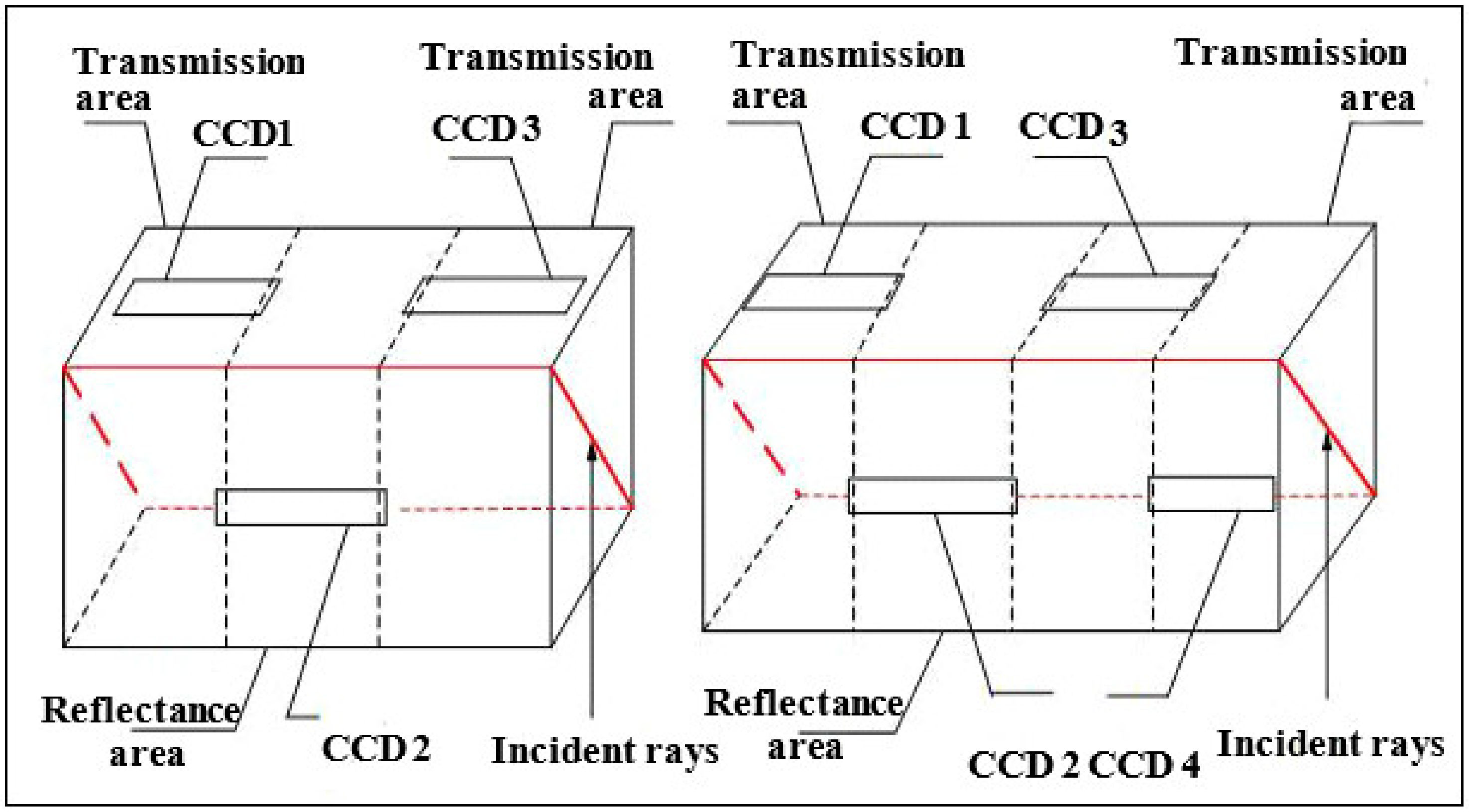
The optical butting scheme arranges multiple chips as an equivalent, long-line CCD array through an optical mirror. Ideally, the misalignment of each chip along the orbit direction is zero allowing the formation of a continuous straight line on the focal plane, which results in few difficulties in the subsequent mosaic process. The main disadvantages of this include light energy reduction and chromatic aberration from prism splitting and limitations of the stitching length due to the prism material and manufacturing technology. One typical example is the three-line array camera in the ZY-3 satellite, whose nadir-view camera is stitched by three TDI CCD chips, and the front-view and backward-view cameras are stitched by four TDI CCD chips, as shown in Figure 1. Through use of the optical mirror, the optical butting scheme divides the imaging space into the transmission area and the reflectance area, which are separate in space. In the ZY-3 nadir-view camera, TDI CCD chips CCD1 and CCD3 are arranged in the transmission area. TDI CCD chip CCD2 is arranged in the reflectance area. In the ZY-3 front-view and backward-view cameras, TDI CCD chips CCD1 and CCD3 are arranged in the transmission area. TDI CCD chip CCD2 is arranged in the reflectance area in both cameras. The TDI CCD chips in both the transmission area and the reflectance area form an equivalent, long-line CCD array on the focal plane through the optical mirror.
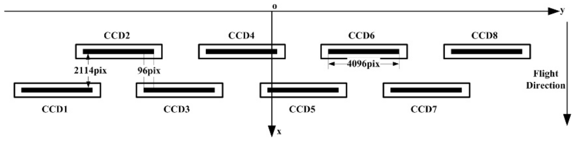
The mechanical interleaving scheme installs multiple CCD, CMOS, or TDI CCD chips into two staggered row configurations on the stitching plate mechanically. The advantage of this is that no additional chromatic aberrations are introduced in imaging, while the disadvantage is that a continuous straight line cannot be formed on the focal plane. The larger the mechanical misalignment, the greater the imaging time delay and the greater the difficulties involved in the subsequent geometric processing. IKONOS, QuickBird, LandSat-8, WorldView-2, French SPOT 6/7, and Chinese TH-1 have all adopted this kind of splicing scheme. Figure 2 shows the focal plane assembly diagram of a 2 m high-resolution (HR) camera in TH-1, which has eight multi-chip CCDs. In Figure 2, each chip contains 4096 photosensitive detector units. The number of overlapping units between adjacent CCDs is constant: 96 overlapping units. For example, the number of overlapping units between CCD1 and CCD2 is 96 units, that of CCD2 and CCD3 is also 96 units, and it is the same for CCD3 and CCD4, CCD5 and CCD6, and CCD7 and CCD8. Along the orbit flight direction the staggering misalignment between two rows is 2114 pixels.

2.2. Geometric Error Characteristics

Systematic errors of spliced satellite optical cameras can be categorized as either external or internal. External errors mainly include errors in satellite attitude measurement, satellite position measurement, camera installation angle, GPS antenna eccentricity, and time synchronization. While the camera installation matrix, the star sensor installation matrix, and the GPS antenna eccentricity are all calibrated in the laboratory before launch, these parameters may deviate considerably during on-orbit operations.
Internal errors mainly include lens error and CCD array error. The sources for lens error consist primarily of the principal point offset, focal length deviation, and optical distortions. The CCD array error sources are composed of the CCD array translation, scaling, and rotation. Internal errors for each chip are generally independent of each other.

2.3. Geometric Imaging Model

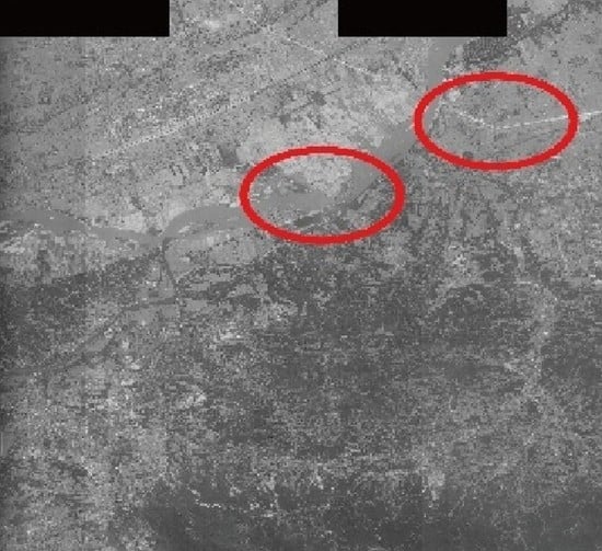
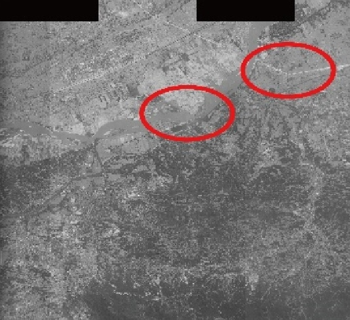
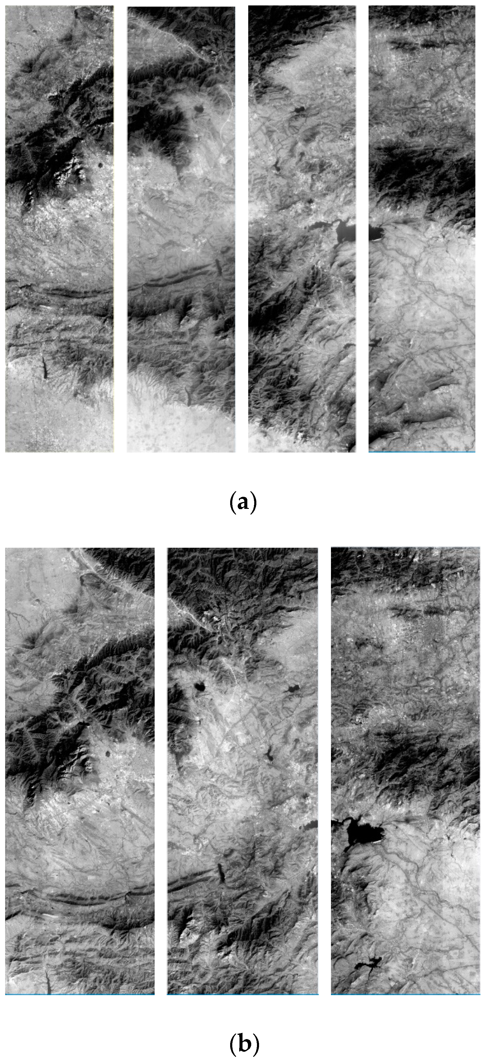
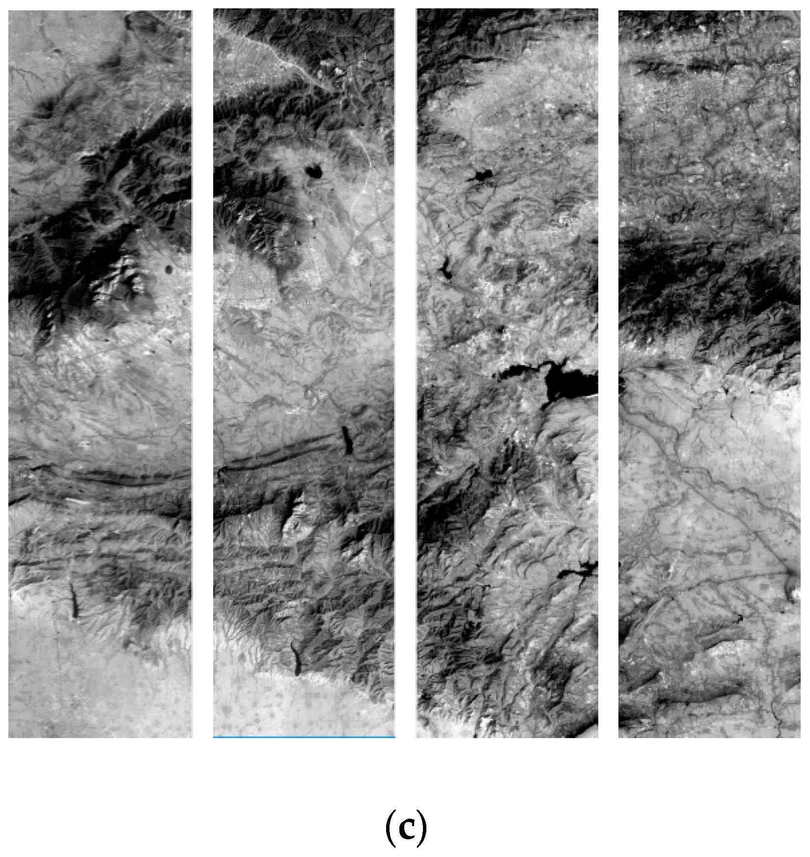
Due to the multi-chip placement position difference on the focal plane, the spliced satellite optical camera does not instantaneously generate a continuous straight line on the ground but instead obtains multiple discontinuous “short scanning lines”, as shown in Figure 3a. The alignment difference in the discontinuous short scan lines along the orbit flight direction depends on the degree of multi-chip misalignment on the focal plane. Each chip acquires push broom images separately along the satellite platform flight and forms multiple-segmented narrow strip images with certain horizontal overlap and vertical misalignment, as in Figure 3b.
For the image point p in the spliced satellite optical image and the ground object point P(X, Y, Z), the rigorous geometric imaging model is set up as follows: the coordinates of image point p in the camera system are f tan φ x , f tan φ y , f :
X Y Z = X S Y S Z S + R J 2000 W G S 84 R B o d y J 2000 R Cam B o d y f tan φ x f tan φ y f + B X B Y B Z
where P(X,Y,Z) represents the ground object point coordinates in the WGS84 coordinate system; R Cam B o d y indicates the installation matrix from the camera system to the satellite body system, predetermined in the laboratory; R B o d y J 2000 is the rotation matrix from the satellite body system to space conventional inertial system (J2000) calculated using satellite attitude data; R J 2000 W G S 84 indicates the rotation matrix from the J2000 system to the WGS84 coordinate system; X s , Y s , Z s are the GPS antenna phase center coordinates obtained from the satellite position measurement data; f t a n φ x , f t a n φ y , f is the image space coordinates represented by the probe pointing angle φ x , φ y . The initial value of φ x , φ y is calculated from the preliminary installation angle of each imaging view and the CCD detector unit size. (BX, BY, BZ) expresses the GPS antenna eccentricity error, which defines the offset vector of the camera projection center relative to the GPS antenna phase center in the satellite body coordinate system. The multi-chip images of the spliced satellite optical camera share one set of satellite orbit and attitude measurement data in a unified camera system. The GPS position and attitude data corresponding to each line in the separate chip can be interpolated from the satellite orbit and attitude data according to the time stamp.
The external geometric calibration is responsible for the accurate determination of the position of the camera’s projection center and the direction of its principal optical axis at the imaging instance. In order to overcome the correlation among the external orientation parameters, the GPS antenna eccentricity (BX, BY, BZ) can be ignored, and its influence is absorbed into the camera alignment angle φ , ω , κ , such that φ is the pitch angle, ω is the roll angle, and κ is the yaw angle. The parameters φ , ω , κ indicate the misalignment matrix R o f f , as shown in Equation (2).
R o f f = cos φ 0 sin φ 0 1 0 sin φ 0 cos φ 1 0 0 0 cos ω sin ω 0 sin ω cos ω cos κ sin κ 0 sin κ cos κ 0 0 0 1
The misalignment matrix includes systematic errors in the satellite orbit and attitude measurement data, the camera installation angle error, and the GPS antenna eccentricity. The main goal of external geometric calibration is to determine the camera alignment angle φ , ω , κ .
Absorbing the misalignment matrix R o f f into Equation (1), the rigorous imaging model with the camera alignment angle is obtained as follows
X Y Z = X S Y S Z S + R J 2000 W G S 84 R B o d y J 2000 R C a m B o d y R o f f f tan φ x f tan φ y f
The multi-chip images of the same view correspond to one misalignment matrix. If the camera is a three-line array stereo CCD camera, such as the TH-1 and ZY-3 optical cameras, three groups of R o f f are utilized to represent the external error in each view.
Internal geometric calibration aims to determine the geometric sight vector for every detector unit in each chip in the camera system and estimate the camera’s intrinsic errors. This process includes the conversion from image point coordinates r , c in the image system to the spatial coordinates x , y , f in the camera system.
(1)
Calculating the chip number i. According to the column c of the image point r , c in the original image system, calculate the point imaged on the i-th chip using Equation (4), where n is the total number of chips in different views, fix indicates the truncating operation, and Ns is the length of a single chip in detector units.
i = f i x c N s + 1   i = 1 , 2 , , n
(2)
Converting the original image system o-rc to the single-chip system oci-xciyci. Calculate the image point coordinates (xci, yci) in the single-chip system based on chip number, where ps is the size of the detector unit in millimeters.
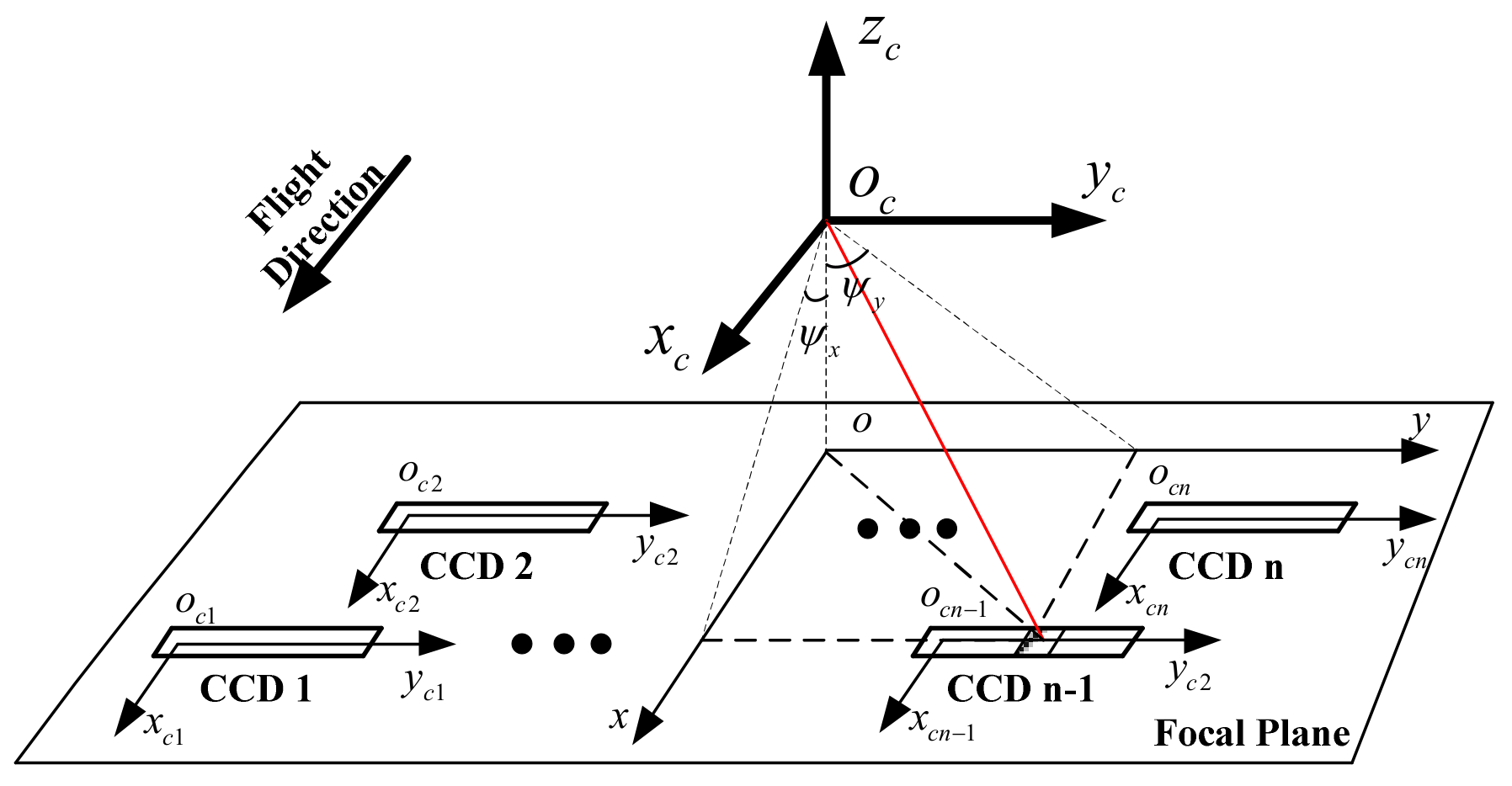
x c i = 0 y c i = c i 1 N s p s
In Figure 4, oci-xciyci is the single-chip system in the focal plane. Each single-chip system takes the center of the left detector unit as the origin, the orbit flight direction as the xci axis, and the scanning direction as the yci axis. oc-xcyczc represents the camera system, and o-xy represents the focal plane system.
(3)
Transforming from the single-chip system oci-xciyci to the camera system oc-xcyczc. Complete the conversion of the single-chip system to the focal plane system o-xy using the placement parameters of each chip in the focal plane, as shown in Equation (6).
x = x c i + x c i 0 y = y c i + y c i 0
Taking the focal length into consideration, the image point coordinates in the camera system can then be determined, which is also the direction of the optical axis.
u 1 = x y f C a m e r a
The optical axis vector x , y , f C a m e r a T in Equation (7) is consistent with f t a n φ x , f t a n φ y , f in the rigorous geometric imaging model (Equation (3)). The optical axis vector can also be normalized into the unit vector u 1 = t a n φ x , t a n φ y , 1 , t a n φ x = x / f , t a n φ y = y / f , as shown in Figure 4.
The camera internal geometric calibration calibrates the probe pointing angle of each detector unit in the camera system. The internal geometric calibration model can take the physical or general model. Currently, the general probe pointing angle is more widely used in airborne and spaceborne linear array camera calibration [27,28,29]. The general internal geometric calibration model is the cubic or high-order polynomial of the column number S on each chip.
S = c i 1 N s tan φ x = c 0 + c 1 S + c 2 S 2 + c 3 S 3 tan φ y = r 0 + r 1 S + r 2 S 2 + r 3 S 3
where c0, c1, c2, c3 are the interior calibration parameters along x axis for each chip, and r0, r1, r2, r3 are the interior calibration parameters along y axis for each chip.
Equations (3) and (8) establish the integral rigorous geometric imaging model for the spliced satellite optical camera. The multi-chip images in each view share the same set of external geometric calibration parameters except for one independent set of interior geometric calibration parameters for various intrinsic errors. The integral rigorous geometric imaging model is the basis for the subsequent external and internal geometric calibration processes.

3. Proposed Integral Geometric Calibration Method Investigation Based on Inter-Chip Geometry Constraints

For a spliced satellite optical camera, the overlapped area of adjacent chips comprises the same ground coverage, which means that one ground point has two corresponding image points in the adjacent overlapped chip area. This supposes that the ground point P(X, Y, Z) forms image point p1(xp1, yp1) on the left chip and the corresponding image point p2(xp2, yp2) on the right chip. For image points p1 and p2, the rigorous geometric imaging models are generated using Equations (9) and (10), where the multiple rotation matrices in Equation (3) can then be combined into Equation (11).
X Y Z = X S 1 Y S 1 Z S 1 + R 1 x 1 y 1 f = X S 1 Y S 1 Z S 1 + R 1 f tan φ x 1 f tan φ y 1 f
X Y Z = X S 2 Y S 2 Z S 2 + R 2 x 2 y 2 f = X S 2 Y S 2 Z S 2 + R 2 f tan φ x 2 f tan φ y 2 f
R = R J 2000 W G S 84 R B o d y J 2000 R C a m B o d y R o f f = a 11 a 12 a 13 a 21 a 22 a 23 a 31 a 32 a 33
where (XS1, YS1, ZS1) and (XS2, YS2, ZS2) are the GPS antenna centers corresponding to the left and right chips, respectively. Combining Equations (9) and (10), the geometry constraint model between adjacent chips can be constructed, as presented in Equation (12).
X S 1 Y S 1 Z S 1 + R 1 x 1 y 1 f = X S 2 Y S 2 Z S 2 + R 2 x 2 y 2 f
The inter-chip geometry constraint model reflects the geometric restricting relationship of the corresponding points in the overlapping chip area. Theoretically, the corresponding image points on the left and right chips coincide on the same ground point. When Equation (12) is met, the corresponding image points on the left and right CCD chips correspond to the same ground point, resulting in seamless stitching of the original multi-chip images and generating continuous and consistent mosaic images without geometric deformation. However, the misalignment error of the adjacent chips, the external error in the imaging process, and the internal error of different chips undermine the geometry constraint (Equation (12)), resulting in geometric mosaic misalignment and reduced positioning accuracy. Therefore, an integral geometric calibration model that considers external and internal errors must be established based on Equation (12). After linearization and expanding the formula using first-order Taylor series, the integral geometric calibration model based on inter-chip geometry constraints is obtained.
X S 1 Y S 1 Z S 1 + R 1 x 1 y 1 f 0 + A 1 Δ φ 1 Δ ω 1 Δ κ 1 + R 1 Δ x 1 Δ y 1 Δ f = X S 2 Y S 2 Z S 2 + R 2 x 2 y 2 f 0 + A 2 Δ φ 2 Δ ω 2 Δ κ 2 R 2 Δ x 2 Δ y 2 Δ f
where Δ φ 1 , Δ ω 1 , Δ κ 1 and Δ φ 2 , Δ ω 2 , Δ κ 2 are the camera alignment angles for the left and right chips, respectively, and, A1 and A2 are the corresponding coefficient matrices. Since all chips of the forward/nadir/backward view share the same set of attitude observation equipment, all chips in each view take one set of camera alignment angles to describe the external error Δ φ 1 , Δ ω 1 , Δ κ 1 = Δ φ 2 , Δ ω 2 , Δ κ 2 = Δ φ , Δ ω , Δ κ . Δ x 1 , Δ y 1 is obtained from the interior calibration parameters of the left chip and is the image point coordinate error for p 1 on the left chip. Δ x 2 , Δ y 2 is calculated by the interior calibration parameters of the right chip and is the image point coordinate error of p 2 on the right chip. The interior calibration parameters for each chip differ from each other. Equation (13) can then be simplified to the expression
X S 1 Y S 1 Z S 1 + R 1 x 1 y 1 f 0 + A 1 Δ φ Δ ω Δ κ + R 1 Δ x 1 Δ y 1 Δ f = X S 2 Y S 2 Z S 2 + R 2 x 2 y 2 f 0 + A 2 Δ φ Δ ω Δ κ R 2 Δ x 2 Δ y 2 Δ f
Equation (14) presents the integral geometric calibration model for spliced satellite optical cameras based on inter-chip geometry constraints proposed in this paper. The geometric calibration operation is performed on spliced optical cameras, which can calibrate the alignment angles and interior calibration parameters for each chip and generate seamless image mosaics and high-precision direct geopositioning. Given the strong correlation between exterior and interior parameters, the external and internal geometric calibration processes need to be implemented separately and iteratively.
The external and internal calibration models can be derived based on the inter-chip geometry constraints. The external calibration model only considers the external errors, i.e., the alignment angles of each view, and assumes the interior calibration parameters to be unchanged. The external geometric calibration model is as follows
A 1 A 2 Δ φ Δ ω Δ κ = l 1
where
l 1 = X S 2 Y S 2 Z S 2 X S 1 Y S 1 Z S 1 + R 2 x 2 y 2 f 0 R 1 x 1 y 1 f 0
The alignment angles Δ φ , Δ ω , Δ κ can be acquired using least squares or linear optimization algorithms. After determining the external calibration parameters and keeping them fixed, the internal geometric calibration model based on inter-chip geometry constraints is established
R 1 Δ x 1 Δ y 1 Δ f R 2 Δ x 2 Δ y 2 Δ f = l 2
If the image point coordinates are represented by the normalized probe pointing angle form, the following model is obtained
R 1 Δ tan φ x 1 Δ tan φ y 1 0 R 2 Δ tan φ x 2 Δ tan φ y 2 0 = l 2
where
Δ tan φ x 1 = d c 0 + d c 1 S 1 + d c 2 S 1 2 + d c 3 S 1 3
Δ tan φ y 1 = d r 0 + d r 1 S 1 + d r 2 S 1 2 + d r 3 S 1 3
Δ tan φ x 2 = d c 0 + d c 1 S 2 + d c 2 S 2 2 + d c 3 S 2 3
Δ tan φ y 2 = d r 0 + d r 1 S 2 + d r 2 S 2 2 + d r 3 S 2 3
R 1 = a 11 a 12 a 13 a 21 a 22 a 23 a 31 a 32 a 33 ,   R 2 = b 11 b 12 b 13 b 21 b 22 b 23 b 31 b 32 b 33
The two items on the left side of Equation (17) can then be expanded to
R 1 Δ tan φ x 1 Δ tan φ y 1 0 = a 11 a 12 a 13 a 21 a 22 a 23 a 31 a 32 a 33 d c 0 + S 1 d c 1 + S 1 2 d c 2 + S 1 3 d c 3 d r 0 + S 1 d r 1 + S 1 2 d r 2 + d S 1 3 r 3 0
R 2 Δ tan φ x 2 Δ tan φ y 2 0 = b 11 b 12 b 13 b 21 b 22 b 23 b 31 b 32 b 33 d c 0 + S 2 d c 1 + S 2 2 d c 2 + d S 2 3 c 3 d r 0 + S 2 d r 1 + S 2 2 d r 2 + S 2 3 d r 3 0
Substituting Equations (18) and (19) into Equation (17), the interior calibration parameters c 0 , c 1 , c 2 , c 3 , r 0 , r 1 , r 2 , r 3 for the left chip and c 0 , c 1 , c 2 , c 3 , r 0 , r 1 , r 2 , r 3 for the right chip can be obtained using least squares adjustment. The internal geometric calibration process is accomplished by establishing Equations (17)–(19) for all chips of each view.
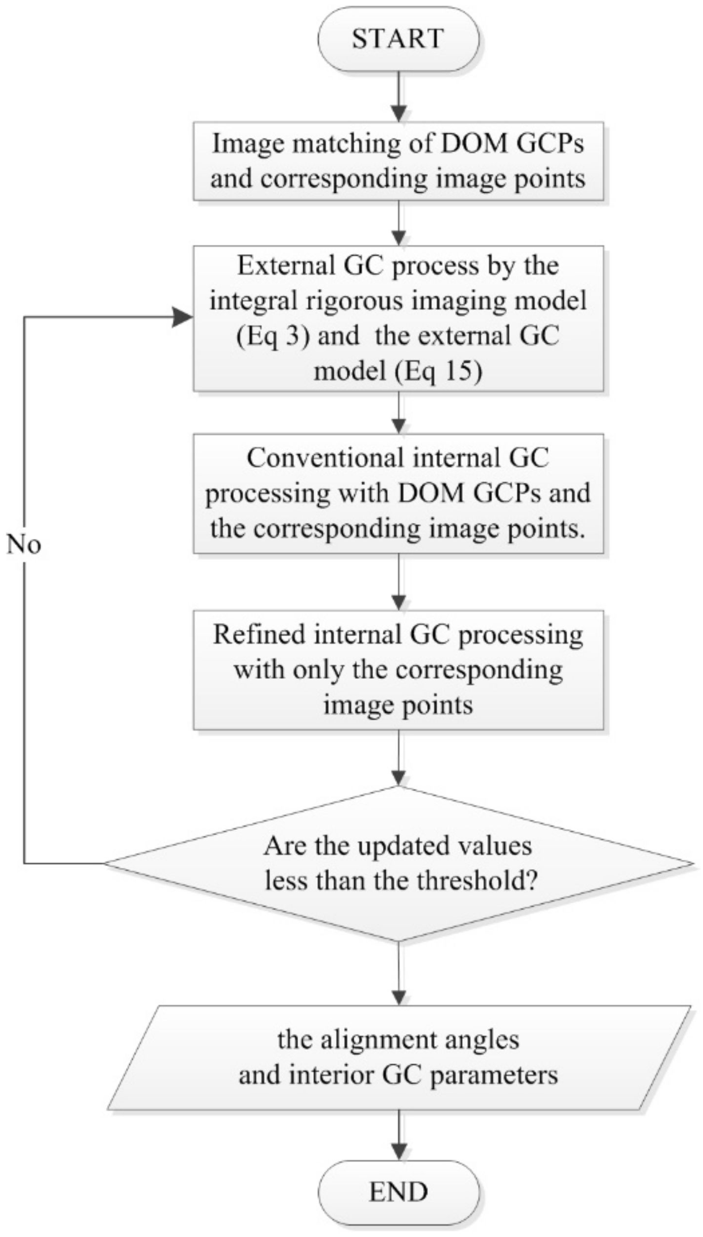
An integral geometric calibration implementation scheme for the spliced satellite optical camera can then be developed according to the inter-chip geometry constraints. The workflow diagram is shown in Figure 5. In order to improve the seamless stitching accuracy for multi-chip images, the internal calibration processing is divided into two steps: conventional processing and refined processing.
(1)
Image matching
Image matching is implemented on each chip and every high-resolution digital orthophoto map (DOM) to automatically obtain DOM GCPs. Image matching is implemented on the multi-chip images to obtain the corresponding image points in the overlap areas of adjacent chips [27,28,30].
(2)
External geometric calibration process
The integral rigorous geometric imaging model is built following Equation (3). Using the corresponding image points, the external calibration model based on inter-chip geometry constraints is formed following Equation (15). The geometric calibration values of the alignment angles are obtained by linearizing and adjusting these two equations together.
(3)
Conventional internal geometric calibration processing
The external calibration parameters are statically fixed, and conventional internal geometric calibration is performed using DOM GCPs and the corresponding image points. For DOM GCPs, the linearized internal calibration equations can be obtained from Equation (3). For the corresponding image points, the internal calibration equations are derived from Equation (17). Conventional geometric calibration is implemented, and the interior calibration parameters for each chip are obtained by adjusting these two equations.
(4)
Refined internal geometric calibration processing
Refined internal geometric calibration is performed by utilizing only corresponding image points to establish the internal calibration error equations based on Equation (17). This step optimizes the interior calibration parameters for each chip and improves the geometric stitching accuracy.
(5)
Iteration
Steps 2 to 4 are repeated iteratively until the generated values for the alignment angles and interior geometric calibration parameters are less than the predefined threshold.

4. Results

4.1. Test Data

Two types of spliced satellite remote sensing data covering the Songshan remote sensing calibration field were used for the experiments. The Songshan calibration field, a national remote sensing calibration field, is located in Songshan District, Dengfeng city, Henan province [27,28]. The Songshan remote sensing calibration field is composed of three parts: the aerial calibration field, the photogrammetry and remote sensing calibration field, and the aerospace calibration field. The aerospace calibration field is about 8000 square kilometers and is mainly used for calibration and validation. Aside from 69 high-precision natural and artificial GCPs, there are two permanent satellite marking sites with 55 GCPs in 2 m, 3 m, and 5 m diameter panels distributed in Dengfeng city, Xinmi city, and Gongyi city. These metal panel GCPs have 0.1 m planar accuracy and 0.2 m elevation accuracy. The calibration field has 0.4 m resolution aerial image data, DSM, DEM, and DOM products.
The ZY-3 and TH-1 satellite image data covering the Songshan calibration field were used for experiments. The nadir-view image resolution of the ZY-3 three-line array camera is about 2.1 m, composed of three TDICCD chips, each containing 8192 TDICCD detector units. The forward- and backward- view images have a ground resolution of about 3.6 m, composed of four TDICCD chips, each containing 4096 TDICCD detector units. The TH-1 satellite high-resolution camera has eight 2 m resolution CCD chips, each with 4096 CCD detector units.

4.2. Experiment Results of ZY-3 Satellite Three-Line Array Images

A set of ZY-3 three-line array satellite images covering the Songshan calibration field, acquired in June 2018, was used for calibration experiments. Figure 6 lists the overview images.

4.2.1. Initial Positioning Accuracy Analysis of ZY-3 Satellite Three-Line Array Images

Using the initial orbit and attitude data of the ZY-3 satellite image, the rotation matrix from the satellite body system to the J2000 system and the matrix from the J2000 system to the WGS84 coordinate system were established. A total of 821 DOM GCPs were obtained, with ground resolution accuracy of 5 cm, to verify and validate the rigorous imaging model and initial geometric positioning accuracy of the ZY-3 three-line array satellite camera. The statistics for the DOM GCP position accuracy are listed in Table 1. Table 1 shows the mean error (Mean), root mean squares error (RMS), maximum error (Max), and minimum error (Min) of all DOM GCPs in the X-, Y-, and Z-directions. In Figure 7, some DOM GCP positioning residuals were plotted at an equal sampling rate. The image shows obvious systematic positioning residuals in both planar and elevation directions.
After obtaining 195 pairs of corresponding image points, two groups of stereo images were formed utilizing the corresponding image points on two adjacent chips. Two sets of ground coordinates were then calculated using space forward intersection. The difference between these two sets of ground coordinates reflects the stitching accuracy of the ZY-3 camera, and the summary of results is presented in Table 2.
In Table 2, since the ZY-3 three-line array camera adopts the optical butting imaging mode, the offset of the corresponding image point in the orbit flight direction between adjacent chips is within one pixel. This suggests that the coordinate differences between two sets of ground coordinates are considerably lower than one meter. Due to the camera internal error and the alignment angle error, the initial geometric positioning accuracy of the corresponding image point is poor. The positioning error can be inversely calculated by averaging the two sets of ground coordinates for each pair of corresponding image points. The statistical results are summarized in Table 3.

4.2.2. Geometric Calibration Accuracy Analysis of ZY-3 Satellite Three-Line Array Images

After the ZY-3 satellite images had been calibrated, the calibrated alignment angles and the interior parameters were obtained. The interior calibration parameters can be used to calculate the probe pointing angle of each detector unit on all chips of every view, forming the calibration pointing angle files. Using the alignment angles and the pointing angle files, the geometric accuracy of the calibrated camera was evaluated using the 821 DOM GCPs, and the statistical values are shown in Table 4. In Figure 8, some DOM GCP’s positioning residuals were plotted at an equal sampling rate. The results suggest that only accidental positioning residuals were left in the planar and elevation directions and that systematic positioning errors had been effectively eliminated.
After geometric calibration, the difference in ground coordinates and the geometric positioning accuracy of 195 pairs of the corresponding image points were evaluated and are summarized in Table 5 and Table 6.
In Table 2 and Table 5, while the original geometric splicing relationship of the ZY-3 satellite is already satisfactory (ground coordinate difference below one meter), geometric calibration was still able to effectively improve the geometric stitching accuracy in all three directions. The geometric positioning accuracy was also enhanced significantly, as shown in Table 3 and Table 6. The geometric calibration experiment confirms that the alignment angles and pointing angle files can effectively compensate for the systematic errors in the satellite imaging process. Using calibrated camera alignment angles and pointing angle files, high positioning accuracy can be achieved.

4.2.3. Validity Assessment of Geometric Calibration Parameters

Three sets of ZY-3 satellite images in Jincheng city, Shanxi Province; Tianjin city, and Shiyan city, Hubei Province were selected to verify the calibrated alignment angles and pointing angle files. Seventeen, fifteen, and sixteen GCPs were taken for verification through field surveying, respectively. Direct uncontrolled geometric positioning was performed based on the alignment angles and pointing angle files, and the positioning accuracy statistics are summarized in Table 7. The ground resolution of the ZY-3 forward-view and backward-view images was 3.6 m, and the RMS errors of uncontrolled positioning in three directions were mostly below two pixels. Only the elevation error for Shiyan city was slightly over two pixels.
Through matching, 121 pairs, 143 pairs, and 168 pairs of the corresponding image points were obtained for Jincheng, Tianjin, and Shiyan, respectively. The ground coordinate differences for the corresponding image points were calculated and are summarized in Table 8. When compared with the RMS errors in Table 2, Table 5, and Table 8, the positioning consistency of the corresponding points improved in all three directions.

4.2.4. Mosaic Effect Verification of ZY-3 Image

Using the calibration parameters, the multi-chip ZY-3 images in the Songshan area were mosaiced with an object stitching algorithm based on the virtual field of view. The mosaic image for the forward view (Figure 6a) is shown in Figure 9, and the inter-chip regions selected from the forward/nadir/backward-view mosaic images are presented in Figure 10. The mosaic image was not feathered, and so, the first and second chips (in Figure 9) are not well-differentiated in close image tone, while the other chips are distinguishable. The red circles in the image (Figure 9) marking road intersections show that the multi-chip images are seamlessly stitched together after geometric calibration.

4.3. Experiment Results of TH-1 HR Image

The TH-1 HR satellite image used in the experiment was taken in 2019 and is shown in Figure 11. The TH-1 high-resolution satellite camera uses the mechanical interleaving imaging scheme, with about 2114 pixels displacement in the orbit flight direction among different chips. Noticeable dislocation can be observed at the junctions of roads and rivers in the image.

4.3.1. Initial Positioning Accuracy Analysis of TH-1 Satellite HR Images

Using the initial orbit and attitude data of the TH-1 satellite HR image, the rotation matrix from the satellite body system to the J2000 system and the matrix from the J2000 system to the WGS84 coordinate system were constructed. A total of 1946 DOM GCPs were obtained through matching with 5 cm resolution DOM image to evaluate the rigorous imaging model and initial geometric positioning accuracy. The statistical results on the DOM GCP position accuracy are summarized in Table 9. In Figure 12, some DOM GCP positioning residuals were plotted at equal sampling rate. The resulting image shows obvious systematic positioning residuals in both planar and elevation directions for DOM GCPs on each chip.
After obtaining 875 pairs of corresponding image points through matching, two groups of ground coordinates were calculated using a mono-image iteration positioning approach based on global 30 m grid SRTM DEM data. The results are summarized in Table 10. The difference between these two sets of ground coordinates reflects the stitching accuracy of the TH-1 HR camera.
For the TH-1 HR camera that uses the mechanical interleaving mode, there were 2114 pixels displacements between adjacent chips along the orbit flight direction. In Table 10, the displacement produced non-negligible impacts on ground coordinates, even if the imaging conditions (e.g., imaging time delay) were precisely controlled. The average for the two groups of ground coordinates was taken, and the resulting values were inversely projected onto the images. The geometric positioning residuals were then calculated, and the summary statistics are presented in Table 11.
Since the TH-1 HR camera has only one imaging view and does not have stereo surveying and mapping capabilities, the ground coordinates used in Table 11 are the intersection points between the optical axis vectors and the earth’s ellipsoid surface, whose positioning accuracy is not as reliable as that of space forward intersection by stereo surveying and mapping camera. This means stereo surveying and mapping camera provides a more reasonable solution.

4.3.2. Geometric Calibration Accuracy Analysis of TH-1 HR Images

After calibrating the TH-1 HR satellite images, the calibrated alignment angles and pointing angle files were obtained. Then, these values were used to reevaluate the geometric positioning accuracy of the DOM GCPs, and the assessment results are in Table 12. In Figure 13, the positioning residuals after geometric calibration were plotted at an equal sampling rate. The resulting plot suggests that only accidental positioning residuals were left in the planar and elevation directions and that systematic positioning errors were effectively removed.
After geometric calibration, the coordinate differences and geometric positioning accuracy for the 875 pairs were calculated, and the summary statistics are presented in Table 13 and Table 14.
Comparing Table 10 and Table 13, the ground coordinate differences for the corresponding image points significantly decreased in three directions after geometric calibration. The geometric stitching accuracy of the TH-1 HR camera was also effectively enhanced, with RMS values all falling within 0.5 m in the X-, Y-, and Z-directions.

4.3.3. Validity Assessment of Geometric Calibration Parameters

Three sets of TH-1 satellite images from Luoyang, Dalian, and Kunming were selected for the direct uncontrolled geometric positioning experiments. Using 21, 19, and 23 GCPs verified by field surveying, the positioning accuracy was evaluated, and the results are summarized in Table 15. The ground resolution of the TH-1 HR image was 2 m, and the RMS errors for uncontrolled positioning were under two pixels in all directions for the three data sets. Through matching, 1123, 1209, and 1147 pairs of corresponding image points were obtained in the overlapping area, and the calculated ground coordinate differences are summarized in Table 16. Comparing Table 10, Table 13 and Table 16, the positioning consistency had considerably improved in the X-, Y- and Z-directions.

4.3.4. Mosaic Effect Verification of TH-1 Image

Using the calibrated alignment angles and pointing angle files, the spliced TH-1 images were mosaiced with an object stitching algorithm based on the virtual field of view. The mosaic image is shown in Figure 14, and the local images between adjacent chips are shown in Figure 15. As shown in the figures, the geometric calibration based on inter-chip geometry constraints significantly improved geopositioning accuracy and resulted in sub-pixel seamless stitching of multi-chip images.

5. Conclusions

A novel geometric calibration method based on inter-chip geometry constraints is proposed for spliced satellite optical cameras. The proposed geometric calibration effectively rectifies the camera’s internal and external errors, enhances geometric imaging consistency, and improves ground geometric accuracy among multi-chip images. The proposed method obtains reliable camera alignment angles and interior calibration parameters and generates high-precision seamless mosaic images. The calibration scheme is not only suitable for mechanical interleaving cameras with large geometric displacement among multi-chip images but is also effective for optical butting cameras with minor chip offset. In this paper, the Songshan remote sensing calibration field was used for calibration experiments. Multiple sets of satellite data in other regions were also used to evaluate the reliability, stability, and applicability of the calibration parameters. The experimental results show that the proposed geometric calibration is effective in seamless geometric stitching for both types of spliced satellite images, having calibration error within half a pixel and uncontrolled geometric positioning error less than two pixels.
Recently, China’s Gaofen-7 and Gaofen-14 satellites were launched into space and are at the on-orbit geometric calibration stage. Spliced satellite optical cameras have reached sub-meter spatial resolution, which makes the impact of mosaic errors much more significant. For future studies, we will analyze the applicability and usefulness of our proposed geometric calibration on the Gaofen-7 and Gaofen-14 spliced satellite optical cameras.

6. Patents

There is a Chinese National Knowledge Patent 202010887236.6 resulting from the work reported in this manuscript. The Patent has gone through the material inspection.

Author Contributions

Conceptualization, T.W., Y.Z. (Yan Zhang); methodology, T.W., Y.Z. (Yan Zhang) and Y.Z. (Yongsheng Zhang); software, T.W., Y.Z. (Yan Zhang ); validation, Y.Y., L.W.; formal analysis, Z.Z.; writing—original draft preparation, T.W., Y.Z. (Yan Zhang); writing—review and editing, Y.Z. (Yongsheng Zhang), Z.Z. and X.X.; visualization, Y.Y., L.W. All authors have read and agreed to the published version of the manuscript.

Funding

This publication has emanated from research conducted with the financial support of Science Foundation China under grant number 41101396 and 41001262.

Institutional Review Board Statement

Not applicable.

Informed Consent Statement

Not applicable.

Data Availability Statement

Not applicable.

Conflicts of Interest

The authors declare no conflict of interest.

References

  1. Jacobsen, K. Issues and method for in-flight and on-orbit calibration. In Post-Launch Calibration of Satellite Sensors; ISPRS Book Series; Taylor & Francis Group: London, UK, 2004; Volume 2, pp. 83–92. [Google Scholar]
  2. Kornus, W.; Lehner, M.; Schroeder, M. Geometric in-flight calibration of the stereoscopic line-CCD scanner MOMS-2P. ISPRS J. Photogramm. Remote Sens. 2000, 55, 59–71. [Google Scholar] [CrossRef]
  3. Valorge, C.; Meygret, A.; Lebegue, L.; Henry, P.; Gachet, R. Forty years of experience with SPOT in-flight calibration. In Post-Launch Calibration of Satellite Sensors; Taylor & Francis Group: London, UK, 2004; pp. 119–133. [Google Scholar]
  4. Dial, G.; Grodecki, J. IKONOS accuracy without ground control. In Proceedings of the ISPRS Commission I Mid-Term Symposium, Denver, CO, USA, 10–15 November 2002; pp. 10–15. [Google Scholar]
  5. Grodecki, J. IKONOS geometric calibrations. In Proceedings of the ASPRS 2005 Annual Conference, Baltimore, MD, USA, 7–11 March 2005; pp. 7–11. [Google Scholar]
  6. Mulawa, D. On-orbit geometric calibration of the OrbView-3 high resolution imaging satellite. Int. Arch. Photogramm. Remote Sens. Spat. Inf. Sci. 2004, 35, 1–6. [Google Scholar]
  7. Venecia, K.; Manager, P.; Systems, B. Rigorous sensor modeling and triangulation for Orbview-3. In Proceedings of the ASPRS Annual Convention, Reno, NV, USA, 1–5 May 2006; p. 30. [Google Scholar]
  8. Gruen, A.; Kocaman, S.; Wolff, K. Calibration and validation of early ALOS/PRISM images. J. Jpn. Soc. Photogramm. Remote Sens. 2007, 46, 24–38. [Google Scholar]
  9. Kocaman, S.; Gruen, A. Orientation and self-calibration of ALOS PRISM imagery. Photogramm. Rec. 2008, 23, 323–340. [Google Scholar] [CrossRef]
  10. Tadono, T.; Shimada, M.; Watanabe, M.; Furuta, R.; Hashimoto, T. Calibration and validation plans of ALOS optical sensors. In Proceedings of the 2004 IEEE International Geoscience and Remote Sensing Symposium, Anchorage, AK, USA, 20–24 September 2004; Volume 3, pp. 1831–1834. [Google Scholar] [CrossRef]
  11. Takaku, J.; Tadono, T. PRISM on-orbit geometric calibration and DSM performance. IEEE Trans. Geosci. Remote Sens. 2009, 47, 4060–4073. [Google Scholar] [CrossRef]
  12. Zhang, Y.; Wang, T.; Feng, W.; Yuan, Z.; Wang, S. Self-calibration block adjustment for Mapping Satellite-1 three-linear CCD image. J. Remote Sens. 2015, 19, 219–227. [Google Scholar] [CrossRef]
  13. Zhang, Y.; Wang, T.; Feng, W.; Wang, S. Positioning technology study for Mapping Satellite-1 islands (reef) imagery with scare controls. Geomat. Inf. Sci. Wuhan Univ. 2016, 41, 617–623. [Google Scholar] [CrossRef]
  14. Wang, J.; Wang, R.; Hu, X.; Su, Z. The On-orbit calibration of geometric parameters of the Tian-Hui(TH-1) satellite. ISPRS J. Photogramm. Remote Sens. 2017, 124, 144–151. [Google Scholar] [CrossRef]
  15. Yang, B.; Pi, Y.; Li, X.; Yang, Y. Integrated geometric self-calibration of stereo cameras onboard the ZiYuan-3 satellite. ISPRS J. Photogramm. Remote Sens. 2020, 162, 173–183. [Google Scholar] [CrossRef]
  16. Wang, T.; Zhang, G.; Li, D.; Tang, X.; Jiang, Y.; Pan, H.; Zhu, X.; Fang, C. Geometric accuracy validation for ZY-3 satellite imagery. IEEE Geosci. Remote Sens. Lett. 2013, 11, 1168–1171. [Google Scholar] [CrossRef]
  17. Pi, Y.; Li, X.; Yang, B. Global iterative geometric calibration of a linear optical satellite based on sparse GCPs. IEEE Trans. Geosci. Remote Sens. 2019, 58, 436–446. [Google Scholar] [CrossRef]
  18. Chen, Y.; Xie, Z.; Qiu, Z.; Zhang, Q.; Hu, Z. Calibration and validation of ZY-3 optical sensors. IEEE Trans. Geosci. Remote Sens. 2015, 53, 4616–4626. [Google Scholar] [CrossRef]
  19. Weser, T.; Rottensteiner, F.; Willneff, J.; Fraser, C. A generic pushbroom sensor model for high-resolution satellite imagery applied to SPOT 5, QuickBird and ALOS data sets. Int. Arch. Photogramm. Remote Sens. Spat. Inf. Sci. 2007, 36, 6. [Google Scholar]
  20. Weser, T.; Rottensteiner, F.; Willneff, J.; Poon, J.; Fraser, C.S. Development and testing of a generic sensor model for pushbroom satellite imagery. Photogramm. Rec. 2008, 23, 255–274. [Google Scholar] [CrossRef]
  21. Zhang, L.; Gruen, A. Multi-image matching for DSM generation from IKONOS imagery. ISPRS J. Photogramm. Remote Sens. 2006, 60, 195–211. [Google Scholar] [CrossRef]
  22. Zhang, L.; Gruen, A. Automatic DSM generation from linear array imagery data. Int. Arch. Photogramm. Remote Sens. Spat. Inf. Sci. 2004, 35, 128–133. [Google Scholar]
  23. Jacobsen, K. Calibration of IRS-1C PAN-camera. In Proceedings of the Joint Workshop “Sensors and Mapping from Space”, Hannover, Germany, 27–30 September 1999; pp. 1–8. [Google Scholar]
  24. Jacobsen, K. Geometric and information potential of IRS-1C PAN-images. In Proceedings of the ISPRS Com I Symposium, Hamburg, Germany, 28 June–2 July 1999; pp. 1–6. [Google Scholar]
  25. Zhang, Y.; Zheng, M.; Xiong, J.; Lu, Y.; Xiong, X. On-orbit geometric calibration of ZY-3 three-line array imagery with multistrip data sets. IEEE Trans. Geosci. Remote Sens. 2014, 52, 224–234. [Google Scholar] [CrossRef]
  26. Tang, X.; Hu, F.; Wang, M.; Pan, J.; Jin, S.; Lu, G. Inner FoV stitching of spaceborne TDI CCD images based on sensor geometry and projection plane in object space. Remote Sens. 2014, 6, 6386–6406. [Google Scholar] [CrossRef] [Green Version]
  27. Wang, T.; Zhang, Y.; Zhang, Y.; Mo, D.; Zhou, L. Investigation on GNSS lever arms and IMU boresight misalignment calibration of domestic airborne wide-field three CCD camera. Acta Geod. Cartogr. Sin. 2018, 47, 1474–1486. [Google Scholar] [CrossRef]
  28. Wang, T.; Zhang, Y.; Zhang, Y.S.; Jiang, G.; Zhang, Z.; Yu, Y.; Dou, L. Geometric calibration for the aerial line scanning camera. Photogramm. Eng. Remote Sens. 2019, 85, 643–658. [Google Scholar] [CrossRef]
  29. Wang, T.; Zhang, Y.; Zhang, Y.S.; Mo, D.; Yu, Y. Geometric calibration of domestic airborne wide-field three-linear CCD camera. J. Remote Sens. 2020, 24, 731–743. [Google Scholar] [CrossRef]
  30. Li, D.; Xiao, X.; Guo, B.; Jiang, W.; Shi, Y. Oblique image based automatic aerotriangulation and its application in 3D city model reconstruction. Geomat. Inf. Sci. Wuhan Univ. 2016, 41, 711–721. [Google Scholar] [CrossRef]
Figure 1. Optical butting diagram of ZY-3 three-line array camera.
Remotesensing 13 02832 g001
Figure 2. TH-1 HR camera focal plane assembly diagram.
Remotesensing 13 02832 g002
Figure 3. The ground coverage diagram of the spliced satellite optical camera at the imaging moment. (a) The instantaneous imaging diagram; (b) Ground coverage of each chip.
Remotesensing 13 02832 g003
Figure 4. Optical butting diagram of ZY-3 three-line array camera.
Remotesensing 13 02832 g004
Figure 5. Workflow of the integral geometric calibration implementation scheme for the spliced satellite optical camera based on inter-chip geometry constraints.
Remotesensing 13 02832 g005
Figure 6. ZY-3 satellite three-line array test data. (a) 4 TDICCD overview images of the forward view; (b) 3 TDICCD overview images of the nadir view; (c) 4 TDICCD overview images of the backward view.
Remotesensing 13 02832 g006aRemotesensing 13 02832 g006b
Figure 7. Initial positioning residuals distribution of ZY-3 three-line array camera. (a) Positioning residuals in XY planar direction; (b) Positioning residuals in the elevation direction.
Remotesensing 13 02832 g007
Figure 8. The positioning residuals distribution of ZY-3 three-line array camera after geometric calibration. (a) Positioning residuals in XY planar direction; (b) Positioning residuals in the elevation direction.
Remotesensing 13 02832 g008
Figure 9. Mosaic image for the 4 TDICCD chips in the forward view.
Remotesensing 13 02832 g009
Figure 10. Zoomed views of forward/nadir/backward mosaic images.
Remotesensing 13 02832 g010
Figure 11. TH-1 HR camera image.
Remotesensing 13 02832 g011
Figure 12. Initial positioning residuals distribution of TH-1 HR camera. (a) Positioning residuals in XY planar direction; (b) Positioning residuals in the elevation direction.
Remotesensing 13 02832 g012
Figure 13. Positioning residuals distribution of TH-1 HR camera after geometric calibration. (a) Positioning residuals in the XY planar direction; (b) Positioning residuals in the elevation direction.
Remotesensing 13 02832 g013
Figure 14. Mosaic Image for TH-1 HR Camera.
Remotesensing 13 02832 g014
Figure 15. Zoomed Views of Mosaic Image.
Remotesensing 13 02832 g015
Table 1. Initial positioning accuracy of ZY-3 three-line array camera. (Unit: meter).
IndexMeanRMSMaxMin
X−455.26474.79−464.70−479.25
Y−722.65735.01−729.97−751.30
Z420.39430.07433.23413.82
Table 2. Ground coordinates differences statistics of ZY-3 three-line array camera corresponding image points. (Unit: meter).
IndexMeanRMSMaxMin
X−0.2270.1870.285−0.604
Y−0.0640.0640.420−0.177
Z−0.1440.1720.152−0.560
Table 3. Initial positioning accuracy of the corresponding image points on the ZY-3 three-line array camera.
IndexMeanRMSMaxMin
X (meter)−572.601593.430−551.473−614.118
Y (meter)−821.815849.581−837.429−862.278
x (pixel)−197.890206.185−189.706−214.176
y (pixel)−273.990279.313−265.265−286.139
Table 4. Geometric calibration accuracy of ZY-3 three-line array camera. (Unit: meter).
IndexMeanRMSMaxMin
X0.0030.3310.642−0.600
Y−0.0080.3690.563−0.992
Z−0.0260.4640.571−0.290
Table 5. Ground coordinates differences statistics of ZY-3 three-line array camera corresponding image points after geometric calibration. (Unit: meter).
IndexMeanRMSMaxMin
X0.0230.0640.095−0.089
Y−0.0140.0320.040−0.078
Z−0.0120.0520.106−0.096
Table 6. Positioning accuracy of the corresponding image points after geometric calibration.
IndexMeanRMSMaxMin
X (meter)0.0090.2190.446−0.444
Y (meter)−0.0050.2400.425−0.661
x (pixel)0.0030.0770.167−0.159
y (pixel)0.0010.0890.135−0.297
Table 7. Direct uncontrolled positioning accuracy based on calibrated alignment angles and pointing angle files. (Unit: meter).
DataXYZ
MeanRMSMaxMinMeanRMSMaxMinMeanRMSMaxMin
Jincheng0.2055.3278.341−6.749−0.1956.8249.486−5.904−0.2146.9366.628−5.420
Tianjin0.1825.2088.012−7.012−0.1776.5789.103−6.976−0.1896.8127.019−6.971
Shiyan0.1985.3119.154−7.423−0.1866.9608.999−7.012−0.1977.1267.238−6.899
Table 8. Ground coordinates differences statistics based on calibrated alignment angles and pointing angle files. (Unit: meter).
DataXYZ
MeanRMSMaxMinMeanRMSMaxMinMeanRMSMaxMin
Jincheng0.0230.0680.112−0.188−0.0190.0390.103−0.077−0.0210.0530.106−0.146
Tianjin0.0190.0410.103−0.113−0.0120.0410.089−0.072−0.0180.0580.116−0.089
Shiyan0.0240.0630.107−0.109−0.0210.0330.097−0.080−0.0190.0590.118−0.112
Table 9. Initial positioning accuracy of TH-1 HR camera. (Unit: meter).
IndexMeanRMSMaxMin
X646.785663.282750.659639.328
Y144.638217.744147.680−740.844
Z118.620231.315308.698−527.600
Table 10. Ground coordinates differences statistics of the corresponding image points. (Unit: meter).
IndexMeanRMSMaxMin
X−2.8493.6205.441−6.813
Y−1.1251.5872.876−4.857
Z−0.1311.8255.387−5.336
Table 11. Initial positioning accuracy of TH-1 HR camera.
IndexMeanRMSMaxMin
X−0.0002.4126.139−6.142
Y0.0041.6284.313−4.257
Z−0.0001.2063.069−3.071
Table 12. Geometric calibration accuracy of TH-1 HR camera. (Unit: meter).
IndexMeanRMSMaxMin
X−0.0130.8341.120−1.019
Y0.0320.9771.092−1.159
Z0.0270.8581.101−1.012
Table 13. Ground coordinate differences statistics of the corresponding image points after geometric calibration. (Unit: meter).
IndexMeanRMSMaxMin
X−0.0320.1040.230−0.311
Y−0.0970.1820.164−0.288
Z0.0230.1170.456−0.276
Table 14. Positioning accuracy of the corresponding image points after geometric calibration.
IndexMeanRMSMaxMin
X (meter)0.0110.2890.654−0.527
Y (meter)0.0060.2980.725−0.786
x (pixel)0.0040.1470.329−0.259
y (pixel)0.0020.1490.365−0.337
Table 15. Direct uncontrolled positioning accuracy based on calibrated alignment angles and pointing angle files. (Unit: meter).
DataXYZ
MeanRMSMaxMinMeanRMSMaxMinMeanRMSMaxMin
Luoyang0.0893.7385.355−4.5960.0253.1605.253−4.7040.0843.5645.145−4.891
Dalian0.0783.8125.049−5.0170.0193.3525.140−5.1040.1013.5725.212−5.089
Kunming0.0863.4154.883−4.0660.0173.2014.953−4.6720.0413.3644.887−4.678
Table 16. Ground coordinates differences statistics based on calibrated alignment angles and pointing angle files. (Unit: meter).
DataXYZ
MeanRMSMaxMinMeanRMSMaxMinMeanRMSMaxMin
Luoyang−0.0470.1370.777−0.387−0.0250.2800.405−0.1390.0880.1680.212−0.418
Dalian−0.0510.1480.890−0.481−0.0310.1970.414−0.1420.0790.1730.232−0.389
Kunming−0.0390.1520.695−0.492−0.0290.1280.501−0.1520.0760.1820.240−0.392
Publisher’s Note: MDPI stays neutral with regard to jurisdictional claims in published maps and institutional affiliations.

