1. Introduction
Information from space-borne instruments has provided long term observational science data by acquiring imagery of the Earth. Various sensors collect data with different spatial resolutions and their spectra span wavelengths from the visible through the infrared. Satellite thermal infrared remote sensing data have many applications, from surface materials and features, such as soil moisture, to surface temperature mapping [
1]. Calibration is crucial before these Earth observations are used.
The Visible Infrared Imaging Radiometer Suite (VIIRS), a major Earth observing instrument aboard the Suomi National Polar-orbiting Partnership (S-NPP) satellite, has operated on-orbit for over three years [
2]. The VIIRS instrument is designed to extend the measurements from the Moderate Resolution Imaging Spectroradiometer (MODIS), another key instrument of NASA Earth observation missions. MODIS is onboard the Terra and Aqua satellites and has operated for over fifteen and thirteen years, respectively [
3]. It is a multispectral sensor that collects data for studying land, atmosphere, and ocean features [
4,
5]. Nearly 40 scientific products have been derived from MODIS calibrated data [
5]. Collection 6 is the latest released L1B product version, which includes several major improvements to the calibration to handle various issues with the aging MODIS sensors [
6].
Toller
et al. [
3] and Xiong
et al. [
7] have provided details on MODIS thermal emissive bands (TEB), on-board calibration algorithms, characteristics, performance, challenging issues, and lessons learned, such as a long wavelength infrared focal plane assembly optical leak and accurately tracking the scan mirror response
versus scan angle changes over time. A number of approaches are used to independently track the performance of Aqua MODIS (hereafter MODIS) Level 1B TEB, which includes reference to near-surface temperature observations over Dome Concordia, Antarctica [
8], comparison of the simultaneous nadir overpasses (SNO) measurements with the Infrared Atmospheric Sounding Interferometer [
9] and the Atmospheric Infrared Sounder (AIRS) [
10,
11]. VIIRS on-orbit calibration methodology and early performance has been reported in several studies [
12,
13,
14]. In addition to the evaluation based solely on VIIRS calibration data, other investigators have conducted inter-comparisons with different sensors. Example MODIS-VIIRS inter-comparisons include (1) scene-based cross-comparison [
15]; (2) SNO data for tracking and evaluation of the RSB stability and performance [
16]; and (3) SNO data for assessing the calibration consistency of TEB bands [
17]. In the study by Efremova
et al. [
17], the SNO data of S-NPP VIIRS (hereafter VIIRS), MODIS, and S-NPP CrIS were collected in the CrIS footprints for VIIRS-MODIS inter-comparison, in which CrIS measurements were used as a transfer reference to derive the bias correction caused by different relative spectral response (RSR) functions between VIIRS and MODIS. Their results showed that the RSR-corrected brightness temperature (BT) differences between VIIRS and MODIS are exceptionally small and are generally within ±0.2 K over the entire scene temperature range using ten SNO datasets between August 2013 and July 2014.
AIRS and CrIS are hyperspectral infrared sounders on board the Aqua and S-NPP satellites, respectively. AIRS is a grating spectrometer with multiple detector arrays for the corresponding spectral channels while CrIS is an interferometer. Both of the two hardware approaches achieve nearly the same spectral characteristics. Details on their calibration and performance are found in [
18,
19,
20].
Since MODIS is a heritage sensor for VIIRS, their consistency in measurements is very important for extending the current MODIS scientific products. This study extends the previous work [
17] comparing VIIRS and MODIS TEB using CrIS in two respects: (1) AIRS hyperspectral measurements are included. This allows for a RSR correction to achieve a better spectrally-matched VIIRS and MODIS TEB than the use of CrIS hyperspectral data alone; (2) this study extends the previous results from limited SNO events to an extensive dataset which covers a complete latitude range from 82°S to 82°N.
Section 2 introduces data features of the four sensors.
Section 3 provides general information on the TEB on-orbit calibration. Inter-comparison methodology and data processing are introduced in
Section 4;
Section 5 shows inter-comparison results and provides a discussion of the results; and
Section 6 is a summary of our analysis.
2. Sensor Data Features
VIIRS has 16 moderate-resolution bands (750 m at nadir) and five image-resolution bands (375 m at nadir). Among them, there are 14 reflectance solar bands (RSBs, imaging bands I1-3, moderate-resolution bands M1-11) with wavelengths ranging from 0.4 to 2.3 μm and seven TEBs (imaging bands I4-5, moderate-resolution bands M12-16) covering a spectral range from 3.6 to 12.5 μm. VIIRS Earth view scenes in the moderate-resolution bands contain 3200 samples in the scan direction within a scan angle range of ±56° off nadir and 16 detectors in the track direction.
MODIS has 20 RSBs (bands 1–19, 26) with wavelengths ranging from 0.4 to 2.3 μm and 16 TEBs (bands 20–25, 27–36) covering a spectra range from 3.6 to 14.4 μm. The RSB sensors have three ground resolutions (250, 500, and 1000 m) at nadir, while all TEB sensors have 1000 m ground resolution at nadir. MODIS Earth view scenes in the 1-km resolution bands contain 1354 samples in the scan direction within a scan angle range of ±55° off nadir and 10 detectors in the track direction.
AIRS provides atmospheric emission spectra to derive temperature and humidity profiles with high precision. Its thermal infrared spectra span 3.7 to 15.4 μm with 2378 spectral channels. AIRS is an across track scanning system with scan range of ±49.5°, centered at nadir. A nominal scan line covers 90 infrared footprints, which corresponds to a ground resolution of 13.5 km at nadir at a satellite altitude of 705.3 km. In contrast to AIRS, CrIS is a Fourier transform spectrometer, which measures radiance for retrieving profiles of temperature, pressure, and moisture. It has 1305 spectral channels covering three wavelength ranges: shortwave infrared (3.92–4.64 μm), mid-wave infrared (5.71–8.26 μm), and long-wave infrared (9.14–15.38 μm). Its scan range covers ±50° with 30 Earth-scene views ( also called field of regard). Each view position includes a 3 × 3 field-of-view (FOV) array. The spatial resolution of each FOV is 14 km at nadir for a satellite altitude of 824 km. Similar to VIIRS and MODIS, AIRS and CrIS also use an internal blackbody (BB) and a deep space view (SV) to maintain their calibration on-orbit.
Both VIIRS and MODIS TEB wavelengths are within the AIRS and CrIS hyperspectral coverage. Since there are regular SNO occurrences between S-NPP and Aqua, both AIRS and CrIS hyperspectral measurements can be used to provide a simultaneous RSR correction between VIIRS and MODIS spectrally-matched TEB, enabling a precise evaluation of the calibration difference between the two sensors. Furthermore, since MODIS and AIRS are on board of the Aqua satellite and VIIRS and CrIS are on board of the S-NPP satellite, more frequent SNO data could be collected due to the fact that their orbits are nearly parallel.
3. VIIRS and MODIS TEB On-Orbit Calibration
The TEB calibration describes the relationship between the digital response of a detector and the sensor's at-aperture radiance. Both VIIRS and MODIS TEB use the onboard BB and SV observations to perform their onboard calibration. BB and SV are viewed every scan to provide scan-by-scan calibration coefficients. The BB is designed to ensure a high effective emissivity and temperature uniformity. The emissivity are greater than 0.992 for MODIS and 0.997 for VIIRS [
21,
22]. The temperature of the onboard blackbody are controlled at 292.5 K during normal operations on VIIRS and 285 K on MODIS. Quarterly warm-up cool-down (WUCD) activities are scheduled so the measurements can be used to derive the calibration offset and nonlinear coefficient. During each WUCD event, blackbody temperatures vary from 267 K to 315 K for VIIRS and from 270 K to 315 K for MODIS.
A quadratic algorithm is currently used in the TEB calibration. The expression for VIIRS TEB radiance calculation is [
23]:
where
RVS and
T represent response
versus scan-angle and temperature;
L and
ρ are temperature-dependent spectral radiance and spectral reflectance;
dn is the background corrected digital count;
EV,
SV,
rta, and
ham represent Earth view, space view, rotating telescope assembly, and half angle mirror (HAM), respectively.
c0,
c1, and
c2 are calibration coefficients for each band, detector, and HAM side. Currently, prelaunch calibration coefficients (
c0,
c1, and
c2) are used in VIIRS TEB calibration. The on-orbit calibration scaling factor,
F, is calculated on a scan-by-scan basis from BB measurements [
23].
For MODIS, the TEB radiance is computed by:
where
L is spectral band averaged radiance and
SM represents scan mirror.
a0,
b1, and
a2 are calibration coefficients for each band, detector, and mirror side.
a0 and
a2 are based on prelaunch tests and are adjusted using an iterative approach to account for the on-orbit drifts [
24], and
b1 is calculated from the BB radiance on a scan-by-scan basis (except for band 21).
4. VIIRS-MODIS Inter-Comparison Methodology
In this paper, the VIIRS-MODIS inter-comparison is conducted using SNO observations. The orbital parameters of the Aqua and S-NPP satellites were obtained from the two-line element sets [
25]. The SNO criterion is set to within 30 s in determining the crossover periods between Aqua and S-NPP orbits. A set of L1B 5-min granules of VIIRS, MODIS, as well as corresponding AIRS L1B granules and CrIS SDR granules, are first selected based on predicted SNO time periods. Then the radiances of each infrared sounder FOV from the SNOs are extracted according to overpass time and geolocation.
For the comparison of measurements from different sensors, all data were converted to the same spectral and spatial grid.
Table 1 lists information on VIIRS, MODIS, AIRS, and CrIS spectral bands. In our analysis, the high spatial resolutions of MODIS L1B data and VIIRS Level 1 5-min data were aggregated into each AIRS and CrIS FOV in order to match the footprint. The radiance difference between VIIRS and MODIS TEB due to their RSR differences was derived by the comparison to the integrated AIRS and CrIS hyperspectral data.
Table 1.
VIIRS, MODIS, AIRS, and CrIS spectral bands.
Table 1.
VIIRS, MODIS, AIRS, and CrIS spectral bands.
| Onboard Satellite | Spectral Channels | Spectral Range (μm) | Nadir Spatial Resolution | # of Samples in Scan | Scan Angle Range |
|---|
| VIIRS | S-NPP: 3+years | TEB | I-bands | I4–I5 | 3.6~12.5 | 375 m
750 m | 3200 | ±56° |
| M-bands | M12–M16 |
| MODIS | Aqua: 13+years | TEB | band 20–25, 27–30 | 3.6~9.8 | 1 km | 1354 | ±55° |
| band 31–36 | 11~14.4 |
| CrIS | S-NPP: 3+years | 1305 spectral channels | 3.92~4.64 5.71~8.26 9.14~15.38 | 14 km | 30; 3 × 3 FOV | ±50° |
| AIRS | Aqua: 13+years | 2378 spectral channels | 3.74~4.61 6.2~8.22 8.8~15.4 | 13.5 km | 90 | ±49.5° |
4.1. Aggregation of Higher Spatial Data in Infrared Sounder FOV
AIRS data at nadir were taken from six footprints (~±3.3°) around the center. VIIRS and MODIS radiance at nadir were defined as the data within a range of ±10 degrees from nadir to get a stable aggregated value. For each AIRS footprint, all pixels of VIIRS and MODIS radiance measurements within a 6.75 km radius of the AIRS pixel center during each SNO were averaged, respectively. Here we assume the FOV spatial response is evenly distributed. Typically, one AIRS footprint includes 140 MODIS pixels and more than 240 VIIRS pixels (750 m resolution). In our analysis, only footprints that are covered by more than 100 MODIS pixels and 180 VIIRS pixels (750 m) were accepted in the SNO data collection.
The same method was applied to CrIS SDR nadir pixels (two center field of regards, around ±3.3° scan angle), where all MODIS and VIIRS measurements within a 7 km radius of a CrIS pixel center were averaged. In the inter-comparison below, only CrIS FOVs that include more than 110 MODIS pixels and 190 VIIRS pixels (750 m resolution) were extracted in the SNO data collection since each CrIS FOV typically contains ~150 MODIS pixels and more than 260 VIIRS pixels (750 m resolution).
4.2. Sensor Spectral band RSR Matching
The spectral profiles of VIIRS and MODIS TEBs as well as spectra coverage of AIRS and CrIS are illustrated in
Figure 1. The RSR in
Figure 1 describes the system transmission as well as the detector sensitivity. To compare the radiance measurements of a spectrally-matched VIIRS and MODIS band, the bias caused by the RSR difference between the two sensors needs to be removed. In this VIIRS-MODIS inter-comparison, AIRS and CrIS hyperspectral measurements were used to derive the bias. Data from four pairs of spectrally-overlapping VIIRS-MODIS bands, M13-B22 (3.9~4.05 µm), M13-B23 (4.0~4.2 µm), M15-B31 (10.1~11.5 µm), and M16-B32 (11.5~12.5 µm), were analyzed in the following inter-comparisons. Both AIRS L1B data and CrIS SDR data were integrated over MODIS bands 22, 23, 31–32, and VIIRS bands M13, M15-16 separately. For each band, the sensor-dependent RSR function of VIIRS and MODIS was first applied to each infrared sounder (AIRS and CrIS) channel using linear interpolation. Then, for each VIIRS and MODIS TEB band, the simulated radiances from the infrared sounder (AIRS and CrIS) measurements were calculated by:
where “
Lhi” is the band-dependent interpolated radiance and [λ
1, λ
2] is the wavelength range of a band. The difference in simulated radiance between VIIRS RSR and MODIS RSR was derived and used as a bias correction in the VIIRS-MODIS inter-comparison. The RSR correction was implemented for each SNO pixel.
Figure 1.
Spectral distribution of VIIRS and MODIS TEBs, as well as AIRS and CrIS spectra coverage. (radiance unit: W/m2/µm/sr).
Figure 1.
Spectral distribution of VIIRS and MODIS TEBs, as well as AIRS and CrIS spectra coverage. (radiance unit: W/m2/µm/sr).
5. Results and Discussions
In the following inter-comparisons, we extracted SNO data from 24 S-NPP/Aqua orbits during April 2014–March 2015, which includes ~57,500 AIRS footprints along with ~13.3 million VIIRS pixels and ~7.7 million MODIS pixels, as well as from ~72,000 CrIS FOVs matching with ~17 million VIIRS pixels and ~9.7 million MODIS pixels. The SNOs span a latitude ranging from −82 degrees to +82 degrees. To get good quality AIRS data, 467 bad channels and noisy channels were removed based on the channel property list given in [
26] and QA parameter given in each AIRS granule. Only channels with QA less than three were used.
The inter-comparison results in this section were averaged over a radiance interval of 0.02 W/m
2/µm/sr for VIIRS band M13 and 0.2 W/m
2/µm/sr for VIIRS bands M15-16. The latitude bin size in the spatial distribution figures below is five degrees. To determine the VIIRS-MODIS inter-comparison in brightness temperature (BT), the radiance of each SNO was converted into BT using the Planck function. The inter-comparison results below were averaged at BT intervals of 1 K for all bands. Δ
L and ΔBT represent the difference between VIIRS and MODIS measurements in radiance and in BT as calculated by:
The RSR corrected MODIS measurements were derived by:
Δ
Lcorr and Δ
BTcorr represent the difference between VIIRS measurements and RSR corrected MODIS measurements in radiance and BT:
5.1. VIIRS-MODIS Inter-Comparison With RSR Correction from AIRS Measurements
In order to derive the VIIRS-MODIS RSR correction using AIRS measurements, MODIS-AIRS SNOs were first selected and then VIIRS-MODIS-AIRS SNOs were collected based on the geolocation and overpass time for each MODIS-AIRS SNO pixel.
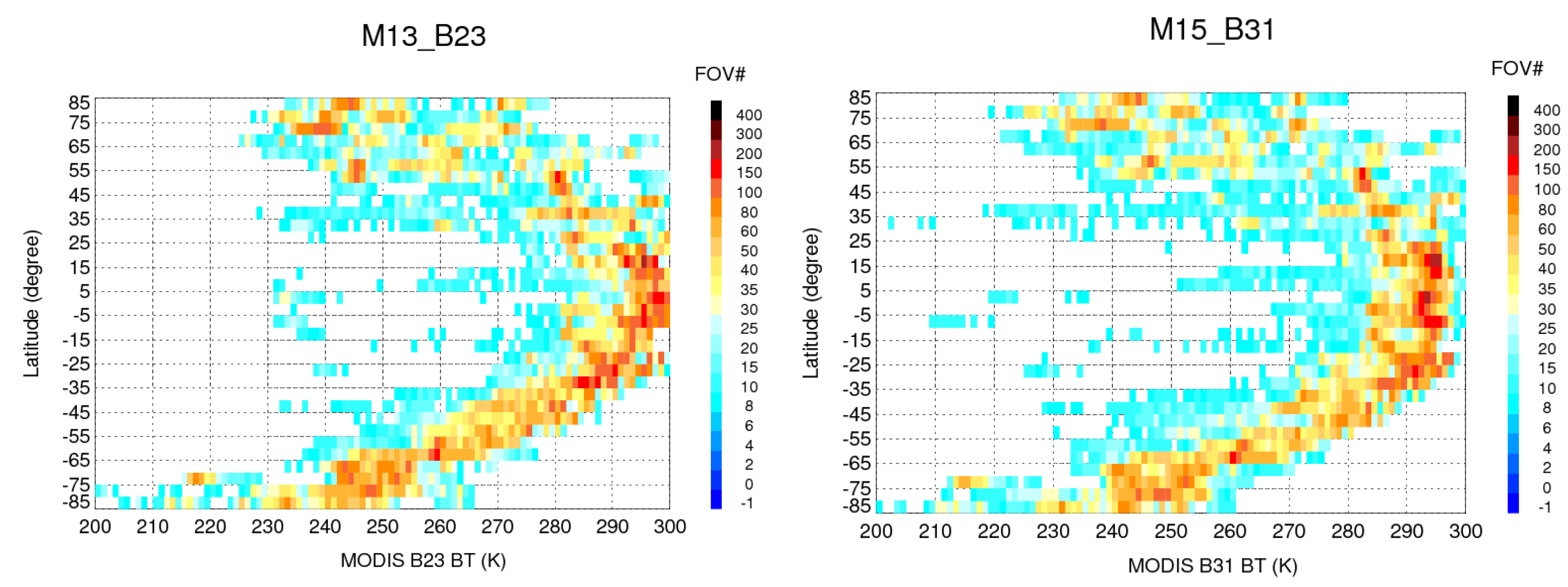
Figure 2 shows the distributions of VIIRS-MODIS-AIRS SNO pixels for VIIRS(M13)-MODIS(B23) and VIIRS(M15)-MODIS(B31).
For each aggregation area (1 K BT by 5° Latitude) shown in
Figure 2, the differences between VIIRS and MODIS measurements from all AIRS pixels within the area were extracted first. A 3-sigma filtering was applied to remove outlier data. Then the mean difference was determined by the average of the filtered data.
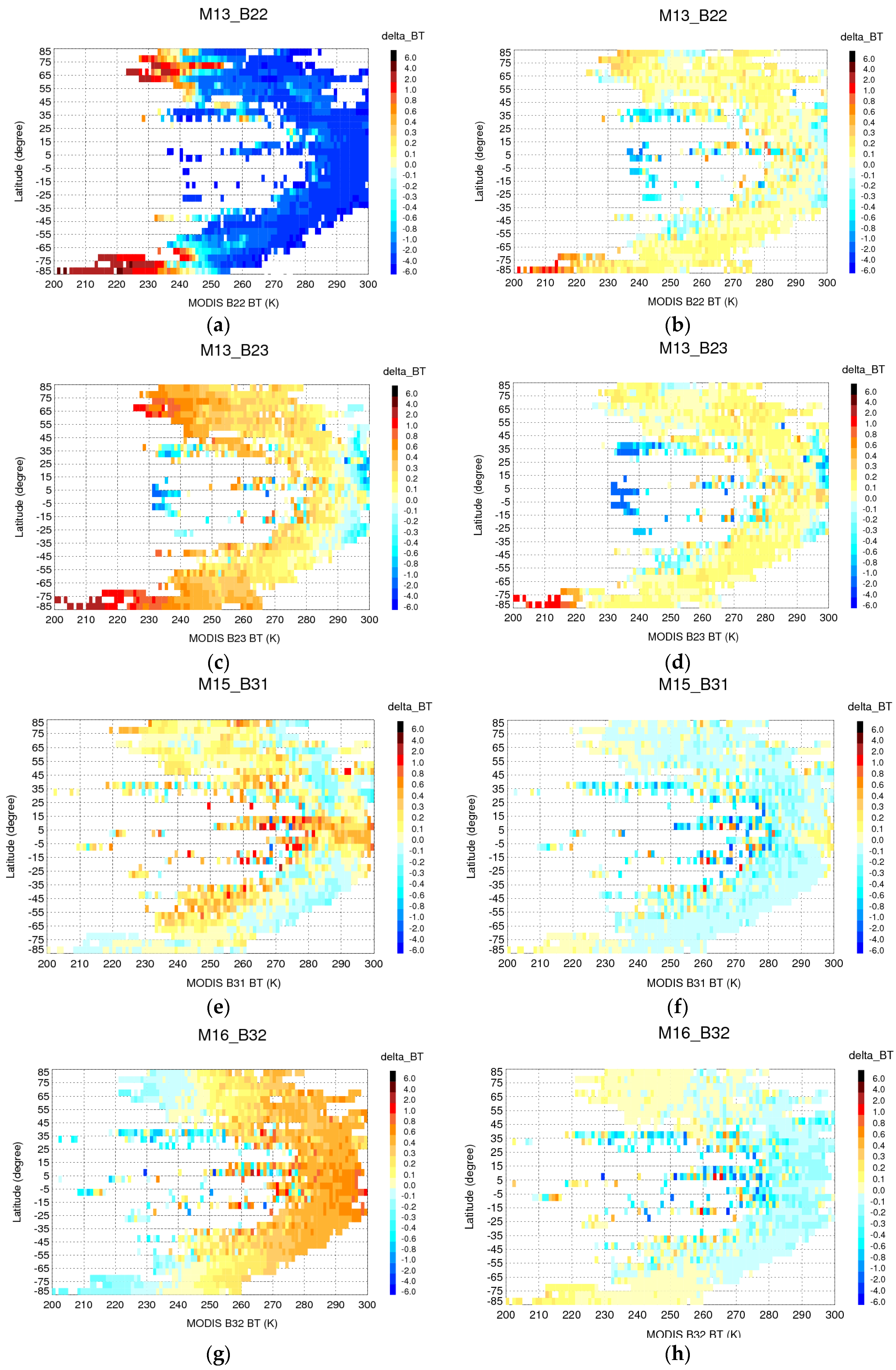
Figure 3a,c,e,g gives the distribution of VIIRS-MODIS inter-comparison directly from VIIRS and MODIS measurements. Since VIIRS-MODIS-AIRS SNOs were collected based on AIRS pixels, the simulated VIIRS radiance and simulated MODIS radiance were calculated for each AIRS pixel. Hence, the ratio between the two simulated radiances was used to correct the radiance caused by the existing difference in RSR for a pair of VIIRS-MODIS bands.
Figure 3b,d,f,h illustrates the distribution of VIIRS-MODIS inter-comparison data after applying the RSR correction.
Figure 2.
VIIRS-MODIS-AIRS SNO FOV number distribution.
Figure 2.
VIIRS-MODIS-AIRS SNO FOV number distribution.
As shown in
Figure 3, the relatively large differences in the M13-B22, M13-B23, and M16-B32 comparisons are mainly caused by differences in their spectral coverage, since the RSR correction significantly improves the agreement. The differences after the RSR correction are well within 0.2 K and nearly constant across the entire temperature and latitude range. There is a slight latitude dependence for M16-B32, which is expected since the bandwidth of M16 is nearly double that of B32. For M15-B31, the RSR correction only produces a small improvement for the differences because they have a smaller bandwidth difference and they are already significantly smaller than the differences for the other band pairs. Moreover, some high differences, shown in the tropical area for BT lower than 270 K, are caused by limited sampling and scene variation (see
Figure 2).
Figure 3.
Distribution of VIIRS-MODIS inter-comparison without/with RSR correction from AIRS measurements. (a) M13_B22 without RSR correction; (b) M13_B22 with RSR correction; (c) M13_B23 without RSR correction; (d) M13_B23 with RSR correction; (e) M15_B31 without RSR correction; (f) M15_B31 with RSR correction; (g) M16_B32 without RSR correction; (h) M16_B32 with RSR correction.
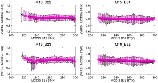
The VIIRS-MODIS differences are plotted as a function of BT before and after the RSR correction (see
Figure 4). The error bars represent the standard deviation for the corresponding BT bin. Results show that the strong dependence of the differences on temperature for M13-B22, M13-B23, and M16-B32 is almost completely removed and the remaining differences are well within 0.2 K. Relatively larger differences are observed at lower BT (less than 240 K) in the M13-B22 and M13-B23 comparisons.
Table 2 lists a quantitative comparison of the results for the four pairs of the bands over a range of BT. VIIRS M14 and MODIS B29 have very close spectral features (see
Figure 1) and their measurements have less than 0.2 K differences (see
Table 2). Since AIRS spectra does not cover M14-B29 range, no RSR correction can be applied to the comparison of the two bands.
Figure 4.
VIIRS-MODIS inter-comparison without/with RSR correction from AIRS (black stars) and CrIS (blue diamonds) measurements, (a) without RSR correction; and (b) with RSR correction.
Figure 4.
VIIRS-MODIS inter-comparison without/with RSR correction from AIRS (black stars) and CrIS (blue diamonds) measurements, (a) without RSR correction; and (b) with RSR correction.
Table 2.
Difference in brightness temperature without/with RSR correction from AIRS measurements (unit: K; RMS: root-mean-square of the bias).
Table 2.
Difference in brightness temperature without/with RSR correction from AIRS measurements (unit: K; RMS: root-mean-square of the bias).
| M13-B22 | M13-B23 | M15-B31 | M16-B32 | M14-B29 |
|---|
| BTMODIS | ΔBT | ΔBTcorr | ΔBT | ΔBTcorr | ΔBT | ΔBTcorr | ΔBT | ΔBTcorr | ΔBT | ΔBTcorr |
|---|
| 220 | - | - | - | - | 0.11 | 0.00 | −0.12 | 0.12 | - | - |
| 230 | 1.47 | 0.16 | 0.80 | 0.04 | 0.11 | −0.01 | −0.08 | 0.04 | −0.02 | - |
| 240 | −0.61 | 0.05 | 0.53 | 0.04 | 0.11 | −0.02 | 0.01 | 0.07 | −0.02 | - |
| 250 | −0.96 | 0.06 | 0.36 | 0.04 | 0.11 | −0.04 | 0.13 | 0.02 | −0.04 | - |
| 260 | −1.31 | 0.10 | 0.37 | 0.14 | 0.14 | −0.02 | 0.25 | −0.00 | −0.08 | - |
| 270 | −2.54 | 0.10 | 0.25 | 0.16 | 0.06 | −0.05 | 0.36 | −0.03 | −0.11 | - |
| 280 | −2.30 | 0.13 | 0.19 | 0.14 | −0.00 | −0.08 | 0.45 | −0.08 | −0.15 | - |
| 290 | −2.80 | 0.07 | 0.04 | 0.12 | 0.11 | −0.04 | 0.58 | −0.10 | −0.19 | - |
| RMS | 1.88 | 0.10 | 0.43 | 0.11 | 0.10 | 0.04 | 0.31 | 0.07 | 0.11 | - |
5.2. VIIRS-MODIS Inter-Comparison With RSR Correction from CrIS Measurements
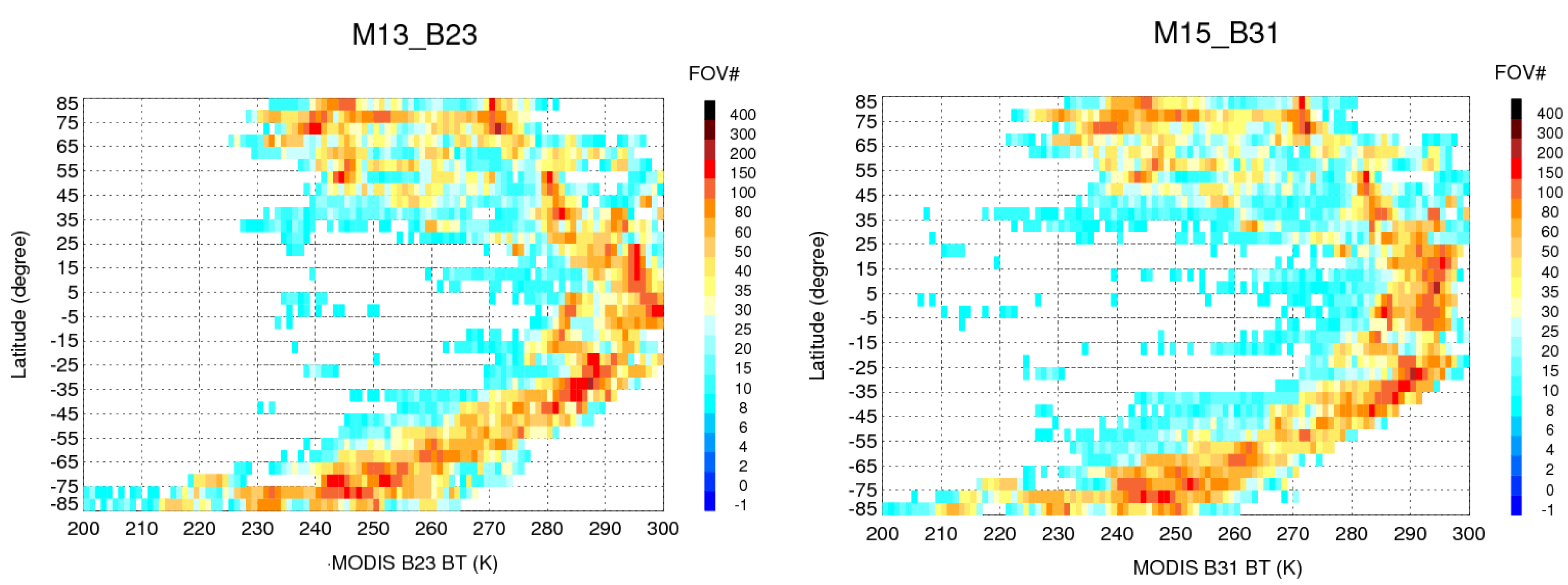
As with the VIIRS-MODIS-AIRS SNO data extraction, VIIRS-CrIS SNOs were collected first because both are onboard the S-NPP satellite. Then VIIRS-MODIS-CrIS SNOs were collected based on the geolocation and overpass time for each VIIRS-CrIS SNO pixel. The spatial distributions of VIIRS-MODIS-CrIS SNO pixel number for M13-B23 and M15-B31 are shown in
Figure 5.
Figure 5.
VIIRS-MODIS-CrIS SNO FOV number distribution.
Figure 5.
VIIRS-MODIS-CrIS SNO FOV number distribution.
Like the data processing method discussed in
Section 5.1, the differences between VIIRS and MODIS measurements from all VIIRS-MODIS-CrIS pixels were extracted. 3-sigma filtering was then applied to remove outliers. The VIIRS-MODIS difference was then determined by the average of the filtered data. The ratio of the simulated VIIRS radiance to the simulated MODIS radiance was derived from CrIS spectral data for each SNO pixel and was used to correct for the RSR difference between the spectrally-matched band pairs.
Figure 6 shows the distributions of VIIRS-MODIS BT differences before and after the RSR correction.
Compared with the distributions resulting from AIRS,
Figure 6 illustrates that the distributions with CrIS SNOs have a much larger spatial coverage. This could be the reason that the BT differences before the RSR correction are slightly larger than those observed in the comparison using AIRS. After the RSR correction, the VIIRS-MODIS differences are much smaller and they are comparable with those after the RSR correction using AIRS. It is very significant that the two independent hyperspectral measurements from AIRS and CrIS, which could have differences due to existing calibration issues with each of the two instruments, can produce nearly the identical results in terms of the RSR correction for the spectrally matched bands between VIIRS and MODIS. The impact of existing measurement offsets in either CrIS and AIRS on the comparison of MODIS and VIIRS should be small because the RSR correction is relative according to Equation (5) and the effective MODIS and VIIRS band widths are narrower than 0.5 µm.
Figure 6.
Distribution of VIIRS-MODIS inter-comparison without/with RSR correction from CrIS measurements. (a) M13_B22 without RSR correction; (b) M13_B22 with RSR correction; (c) M13_B23 without RSR correction; (d) M13_B23 with RSR correction; (e) M15_B31 without RSR correction; (f) M15_B31 with RSR correction; (g) M16_B32 without RSR correction; (h) M16_B32 with RSR correction.
Similarly, the VIIRS-MODIS differences are plotted
versus BT, as shown in
Figure 4. As expected, the results are consistent with those derived using AIRS. It is also noted that the CrIS results cover a wider range of BT than the results using AIRS because more SNO pixels and larger spatial coverage are used.
Table 3 lists the quantitative comparison results over a range of BT and the results indicate that the differences after the RSR correction are well within 0.20 K for all the comparison bands. As seen from
Figure 4 and
Table 2 and
Table 3 and [
27], the differences between AIRS and CrIS measurements could be caused by AIRS and CrIS radiometric differences.
Table 3.
Difference of brightness temperature without/with RSR correction from CrIS measurements (unit: K).
Table 3.
Difference of brightness temperature without/with RSR correction from CrIS measurements (unit: K).
| M13-B22 | M13-B23 | M15-B31 | M16-B32 | M14-B29 |
|---|
| BTMODIS | ΔBT | ΔBTcorr | ΔBT | ΔBTcorr | ΔBT | ΔBTcorr | ΔBT | ΔBTcorr | ΔBT | ΔBTcorr |
|---|
| 220 | 1.36 | 0.35 | 1.12 | 0.36 | 0.15 | 0.01 | −0.15 | 0.08 | −0.09 | - |
| 230 | 0.82 | 0.11 | 0.84 | 0.10 | 0.16 | 0.01 | −0.04 | 0.09 | −0.04 | - |
| 240 | −0.12 | 0.10 | 0.54 | 0.06 | 0.15 | 0.00 | 0.04 | 0.08 | −0.04 | - |
| 250 | −0.96 | 0.08 | 0.44 | 0.05 | 0.18 | 0.00 | 0.20 | 0.07 | −0.05 | - |
| 260 | −1.40 | 0.15 | 0.41 | 0.16 | 0.13 | −0.05 | 0.30 | 0.04 | −0.11 | - |
| 270 | −2.64 | 0.15 | 0.30 | 0.15 | 0.05 | −0.06 | 0.42 | 0.04 | −0.13 | - |
| 280 | −2.26 | 0.14 | 0.25 | 0.15 | 0.06 | −0.07 | 0.53 | 0.01 | −0.18 | - |
| 290 | −2.65 | 0.16 | 0.11 | 0.15 | 0.10 | −0.06 | 0.65 | 0.00 | −0.25 | - |
| RMS | 1.75 | 0.17 | 0.59 | 0.17 | 0.13 | 0.04 | 0.36 | 0.06 | 0.13 | - |
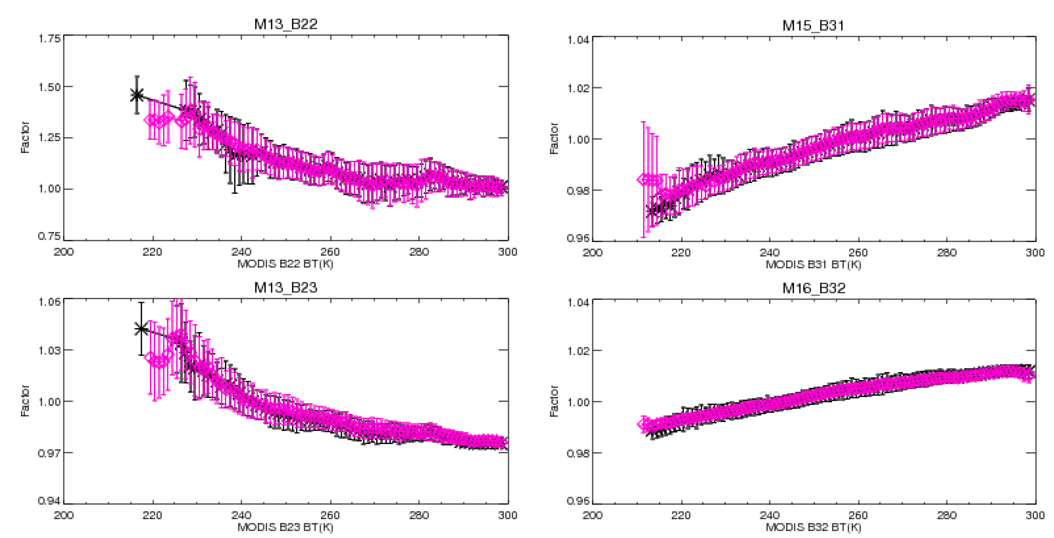
The RSR correction factor is defined as the ratio of simulated radiances using VIIRS RSR and MODIS RSR in Equation (5).
Figure 7 plots of RSR correction factors
versus BT. For M13-B22, M13-B23, M15-B31, and M16-B32, the RSR correction factors match well from AIRS and CrIS measurements. This also indicates that AIRS and CrIS instruments are radiometrically consistent in the proposed SNO inter-comparison approach.
Figure 7.
RSR correction factors from AIRS (black stars) and CrIS (blue diamonds) measurements.
Figure 7.
RSR correction factors from AIRS (black stars) and CrIS (blue diamonds) measurements.
The SNO data was also analyzed in radiance. Instead of the absolute radiance difference, it is expressed as a percentage.
Table 4 summarizes the percent differences of radiance before and after the RSR correction. For longer wavelength bands, after the RSR correction, the differences of VIIRS(M15)-MODIS(B31) and VIIRS(M16)-MODIS(B32) are within 0.1% and 0.2%, respectively, except at very low radiance of 1.0 W/m
2/µm/sr.
Table 4.
Percent difference in radiance without/with RSR correction (LMODIS unit: W/m2/µm/ sr; Δ unit: %).
Table 4.
Percent difference in radiance without/with RSR correction (LMODIS unit: W/m2/µm/ sr; Δ unit: %).
| LMODIS | M13-B22 | M13-B23 | LMODIS | M15-B31 | M16-B32 |
|---|
| AIRS | CrIS | AIRS | CrIS | AIRS | CrIS | AIRS | CrIS |
|---|
| ΔL | ΔLcorr | ΔL | ΔLcorr | ΔL | ΔLcorr | ΔL | ΔLcorr | ΔL | ΔLcorr | ΔL | ΔLcorr | ΔL | ΔLcorr | ΔL | ΔLcorr |
|---|
| 0.1 | 10.42 | 0.65 | 10.02 | 0.88 | −0.74 | 0.36 | −0.29 | 0.62 | 1.0 | −3.28 | 0.28 | −3.69 | 0.24 | −1.07 | 0.53 | - | - |
| 0.2 | 2.27 | 0.62 | 3.79 | 0.63 | −1.08 | 0.71 | −0.84 | 0.72 | 2.0 | −1.77 | 0.01 | −1.78 | 0.10 | −0.48 | 0.22 | −0.47 | 0.22 |
| 0.3 | 6.40 | 0.53 | 5.78 | 0.61 | −1.24 | 0.64 | −0.84 | 0.88 | 3.0 | −1.01 | −0.07 | −0.87 | 0.03 | −0.10 | 0.09 | 0.04 | 0.18 |
| 0.4 | 3.75 | 0.32 | 2.99 | 0.50 | −1.41 | 0.50 | −1.19 | 0.61 | 4.0 | −0.41 | −0.08 | −0.30 | −0.01 | 0.33 | 0.05 | 0.45 | 0.14 |
| 0.5 | 2.34 | 0.19 | 2.19 | 0.52 | −1.75 | 0.49 | −1.41 | 0.72 | 5.0 | 0.01 | −0.11 | 0.07 | −0.09 | 0.58 | −0.05 | 0.70 | 0.08 |
| 0.6 | 0.24 | −0.19 | 1.62 | 0.37 | −2.12 | 0.33 | −1.72 | 0.61 | 6.0 | 0.28 | −0.14 | 0.31 | −0.10 | 0.79 | −0.07 | 0.85 | 0.01 |
| 0.7 | −1.10 | −0.21 | 1.66 | −0.49 | −2.41 | 0.01 | −2.21 | 0.09 | 7.0 | 0.61 | −0.14 | 0.73 | −0.10 | 0.90 | −0.11 | 0.96 | −0.03 |
| 0.8 | −3.71 | −0.46 | −4.51 | −1.99 | −3.12 | -0.57 | −3.96 | −1.5 | 8.0 | 1.00 | −0.10 | 1.01 | −0.10 | 1.07 | −0.14 | 1.16 | −0.02 |
| 0.9 | - | - | −9.70 | −6.53 | - | - | - | - | 9.0 | 1.40 | −0.01 | 1.4 | −0.08 | 1.11 | −0.11 | 1.27 | 0.02 |
5.3. Discussions
For the shorter wavelength bands, VIIRS M13 spectra covers part of MODIS B22 spectra, while the MODIS B23 spectra range is within M13 coverage. This is why larger radiance differences appear in the M13-B22 comparison than between M13 and B23 before the RSR correction, and the differences are still radiance-dependent after the RSR correction. Sparsity of data points causes some fluctuations at the edges of data range.
The BT uncertainties are roughly unchanged after the RSR correction. This is because they are mainly caused by the existing footprint mismatch between the individual hyperspectral pixel and integrated VIIRS and MODIS pixels. Since the AIRS and CrIS footprint sizes are similar, the uncertainty results obtained from using the two hyperspectral sensors are consistent. In this study, the uncertainties are based on 1 sigma and they are within 0.50 K over the entire scene temperature range from 220 K to 300 K. For the atmospheric window bands at 11 and 12 μm, the uncertainty varies with scene temperature. Larger uncertainties occur between BT at 250 and 280 K, where the scene variation is dominant.
The calculation of the RSR correction in this study is based on the in-band RSR for VIIRS and MODIS, respectively. The impact of out-of-band RSR is considered to be negligible. This is based on pre-launch measurements of the in-band and out-of-band RSR. For the thermal emissive bands, the magnitudes of the out-of-band RSR are well within 10−4.


