Article

First Results of a Tandem Terrestrial-Unmanned Aerial mapKITE System with Kinematic Ground Control Points for Corridor Mapping

1
GeoNumerics, Avda. Carl Friedrich Gauss 11, E08860 Castelldefels, Spain
2
Geodetic Engineering Laboratory (TOPO), École Polytécthnique Fédéral de Lausanne (EPFL), Batiment GC Station 18, CH-1015 Lausanne, Switzerland
*
Author to whom correspondence should be addressed.
Submission received: 30 November 2016 / Revised: 1 January 2017 / Accepted: 4 January 2017 / Published: 11 January 2017
(This article belongs to the Special Issue Recent Trends in UAV Remote Sensing)

Abstract

:
In this article, we report about the first results of the mapKITE system, a tandem terrestrial-aerial concept for geodata acquisition and processing, obtained in corridor mapping missions. The system combines an Unmanned Aerial System (UAS) and a Terrestrial Mobile Mapping System (TMMS) operated in a singular way: real-time waypoints are computed from the TMMS platform and sent to the UAS in a follow-me scheme. This approach leads to a simultaneous acquisition of aerial-plus-ground geodata and, moreover, opens the door to an advanced post-processing approach for sensor orientation. The current contribution focuses on analysing the impact of the new, dynamic Kinematic Ground Control Points (KGCPs), which arise inherently from the mapKITE paradigm, as an alternative to conventional, costly Ground Control Points (GCPs). In the frame of a mapKITE campaign carried out in June 2016, we present results entailing sensor orientation and calibration accuracy assessment through ground check points, and precision and correlation analysis of self-calibration parameters’ estimation. Conclusions indicate that the mapKITE concept eliminates the need for GCPs when using only KGCPs plus a couple of GCPs at each corridor end, achieving check point horizontal accuracy of μ E , N 1.7 px (3.4 cm) and μ h 4.3 px (8.6 cm). Since obtained from a simplified version of the system, these preliminary results are encouraging from a future perspective.

Graphical Abstract

1. Introduction

Unmanned Aerial Systems have now became a standard of the mapping community [1]. We have seen in the recent years that small, low-cost and easy-to-operate aerial robots have been used within the Earth observation and mapping field in a wide spectrum of applications. After successful research, the industry panorama has been shaped to the Unmanned Aerial System (UAS) revolution, creating space for new companies and pushing the traditional actors towards its adoption. The only doubt among all these certainties in the UAS niche relates to its future growth quotes and evolution potential. A few well-representative examples of the UAS adoption among the mapping industry are Sensefly’s Swinglet or eBee, Trimble’s UX-5 or Topcon’s Falcon-8, powered by Ascending Technologies. The intensity push from the drone key market industry players has even brought some consumer-grade platforms into the mapping field; e.g., Phantom DJI’s via Pix4D tools.
In the application context of this paper, i.e., mapping of linear corridors—roadways, railways, waterways, pipelines—another revolutionary technology established and capitalised the market some more years ago. Terrestrial Mobile Mapping Systems inherited the lessons from aerial mapping and proposed a new way of acquiring ground-level, geometrically rich and abundant geodata. The production of accurate 3D geoinformation was unleashed by navigation-grade Inertial Navigation Systems (INS) and Global Navigation Satellite Systems (GNSS), used for direct sensor orientation. Terrestrial Mobile Mapping System (TMMS) succeeds when focusing on high-resolution close-range applications, e.g., facades, urban furniture, etc. However, it is constrained to the ill-conditioned navigation conditions due to environmental occlusions, from buildings to forestry or bridges. Additionally, ground-level obstructions in road scenarios (small hills, fences, or simply other vehicles) introduce geodata gaps in TMMS-only surveys, and have a basic lack of the aerial point of view. This supposes a major motivation for tandem and simultaneous aerial-ground mapping concepts, as we propose in mapKITE. We identify initiatives addressing the fusion of UAS images and terrestrial ones [2,3] and the combination of UAS photogrammetry-based 3D models with terrestrial laser scanner point clouds [4]—however, to the best of our knowledge, there is no available approach for simultaneous and kinematic geodata acquisition mode.
Indeed, corridors are challenging scenarios for mapping, and the challenge is even bigger when addressing UAS mapping. Firstly, current UAS architectures with static ground control station limit the UA-to-station distance to the visual line-of-sight. This has a direct impact on mission productivity, especially in the context of long corridors, as the operators have to work on a per-segment basis. Real-time Kinematic (RTK) schemes with static base stations for UAS navigation are also subject to this constraint. Secondly, sensor orientation is an additional challenge in corridors due to the weak geometry (no crossed strips). This weakness is usually addressed by densifying the coverage of Ground Control Points (GCPs) [5] or by INS/GNSS aerial control. About the latter, recent research explores the use of precise position and attitude aerial control to perform direct sensor orientation (DiSO) in corridor blocks [6]. Based also on precise position and attitude aerial control, including only image measurements of a few GCPs, the Fast Aerial Triangulation (Fast AT) concept has been explored for corridor mapping [7]. Avoiding photogrammetric tie point measurements might be the only way to go when flying above ill-textured environments, e.g., rivers, sand, trees, snow, etc.
In this introduction, we have identified weaknesses of the leading mapping technology paradigms for corridor mapping, namely UAS and TMMS, and we have aimed at the combination of these to overcome issues related to mapping (geodata coverage gaps and lack of simultaneous point of view), navigation (weak corridor geometries, high cost GCPs) and operation (per-segment basis due to static set-ups). This paper investigates the mapKITE paradigm for sensor orientation of aerial images in corridors and gives continuity to previous research, where the authors assessed the precision and reliability of the newly proposed orientation approach in a simulated environment, as compared to conventional Integrated Sensor Orientation (ISO), especially targeting the elimination of GCPs as a direct consequence of the mapKITE Kinematic Ground Control Points (KGCPs) [8]. In the current contribution, the authors enhance the previous analysis in the context of a real mapKITE mission performed in June 2016 and include accuracy assessment with ground check points.
The organization of the rest of the paper is as follows: Section 2 will provide the basics about the mapKITE concept and technology, and describe the new features introduced for sensor orientation and calibration. Section 3 reports about real mapKITE missions executed in June 2016 and compiles the obtained results focusing primarily on sensor orientation and calibration. The newly proposed approach, based mainly on KGCPs and a few GCPs, is compared to the traditional approach for corridor mapping, based heavily on GCPs. Finally, we will draw some conclusions and indicate the way forward in Section 4.

2. The mapKITE Concept

In this section, we provide synthetic descriptions of the essentials of mapKITE as well as key references on which the current contribution stands. The reader shall then be able to configure accurate idea about the many aspects that make up the full proposed concept.
At this point, we highlight that mapKITE is a protected concept in terms of intellectual property rights under Spanish patent ES2394540 and US patent 14/417,435.

2.1. A Tandem Terrestrial-Aerial System for Corridor Mapping

The core concept and technologies constituting mapKITE have been already introduced in previous work [9,10]. In general terms, a mapKITE system is a tandem TMMS and UAS equipped with remote sensing instruments that co-operate in the data acquisition task, that is, the waypoints to be followed by the Unmanned Aircraft (UA) are computed at and sent from its Ground Control Station (GCS) installed inside the Terrestrial Vehicle (TV), which is interfaced to the real-time navigation system of the TMMS. In this way, the UA follows the TV. While currently this scheme is widely known as the follow-me guidance mode, we define it as the virtual tether in the mapKITE context, understood as a robust and configurable follow-me.
The virtual tether is a mechanism that adjusts itself to comply with a series of mission requirements, ranging from mapping ones (image footprint size and overlap, ground sampling distance, etc.) to calibration (INS, INS/GNSS and/or camera calibration) and safety (UA-to-GCS distance, robustness against real-time navigation errors, etc.) The continuous-line-of-sight nature of the virtual tether is a productivity booster for the mapKITE concept, as it enables continuous UAS operation well beyond the point where the mission started, in contrast to the usual, less dynamic fly-settle-fly configurations. We therefore present a “mapping kite” with a total point-of-view mapping capability—aerial and ground—suitable for corridor mapping applications such as mapping of roadways, railways, waterways and other linear structures.
Operating a UAS-based solution is a dual challenge on the technical side and also in regards to existing (and limiting) regulations—and mapKITE is not an exception. However, with recent advances such as the approval of the Part 107 on the Operation and Certification of Small Unmanned Aircraft Systems by the Federal Aviation Administration in the United States [11], the expectation is that regulations will downgrade its specific weight within the UAS operation complexity and leave room for innovative approaches such as the one presented in this paper.
We note that mapKITE is a modular concept, in which the selection of the sensors and navigation systems are at the will of the operators and tailored for each specific application. The specific mapKITE configuration used for the results presented in the current contribution is described in Section 3.1.

2.2. Exploiting the High-Quality Ground Trajectory for Aerial Image Orientation

Our concept exploits the high-quality navigation systems in TMMS, both for real-time and post-processing. While the former contributes to the quality of the waypoints generated by the virtual tether, the latter is instrumental for the new concept of sensor orientation and calibration that mapKITE brings into scene.
On one hand, highly accurate and precise post-processed TMMS trajectories are available as they originate due to the geo-referencing needs in mapping applications. On the other hand, a key element is incorporated into a mapKITE set-up: a coded optical target placed on the terrestrial vehicle’s roof. Based on these two elements, we introduce the concept of KGCP, defined as an accurately positioned distinctive point, e.g., center of an optical target strapped to the van. Provided that the optical target enables pointing or pointing-and-scaling photogrammetric measurements—that is, measurement of the image coordinates and scale of the distinctive point—mapKITE, therefore, benefits from an accurate, ready-to-use, dynamic ground control to be used for aerial sensor orientation, which supposes no additional surveying cost.
For the results in the current paper, the optical target used is described in [12], based on the concept of coded targets that enable fast and robust identification.

2.3. Integrated Sensor Orientation Including Photogrammetric Measurements of KGCPs

The approach for sensor orientation and calibration in mapKITE shall be regarded as a natural extension of standard ISO. As such, it relies on a varied control configuration, including the usual ISO aerial control—position-only or position and attitude from post-processed INS/GNSS—it may include conventional GCPs—fewer than in conventional corridor mapping missions—and finally it aims at the use of the new KGCPs. mapKITE fosters the use of Precise Point Positioning (PPP) processing to free the concept from ground GNSS stations. However, the integration of low-cost IMUs with PPP trajectories still needs to be corrected for systematics errors. This argument, added to the fact that camera calibration is still an issue, leads to the need of implementing an ISO approach.
Besides the adoption of new measurements, a mapKITE operation inherently introduces multiple geometries for image acquisition within a single block, which results in favourable conditions for sensor orientation. For example, the take-off and landing stages induce different flying heights, which is beneficial for calibration of the interior orientation elements or the ability to stop the terrestrial vehicle—and therefore, the UA—to convert the KGCP into a conventional GCP in the middle of a corridor. We note that stopping for calibration manoeuvres does not jeopardize the mission productivity as they will not be frequent, while its benefit is noticeable. In [8], improved performance with respect to classical configurations in simulated mapKITE corridors including calibration manoeuvres has already been demonstrated.

3. Corridor Configuration and Preliminary Results

We report now on the geometric performance of the first preliminary implementation of mapKITE. For this, we use the data acquired during the first mapKITE test campaign for basic verification and validation purposes in which the mapKITE prototype underwent exhaustive testing in a corridor mapping scenario. More specifically, we concentrate on the accuracy of the orientation and calibration of the aircraft images.
In the test campaign, a number of flights were conducted according to a simplified mapKITE acquisition concept. A regular mapKITE flight would have included image calibration (opportunistic) manoeuvres benefiting from the (actual) take-off and landing ones. The campaign was not designed for accuracy assessment. To our surprise, however, it delivered geometric results beyond expectation.
This campaign took place during the fourth week of June 2016, at the BCN Drone Center, located in Collsuspina, Spain. The tests focused on mapping a short segment of a rural road within segregated airspace around the BCN Drone Center. As depicted in 
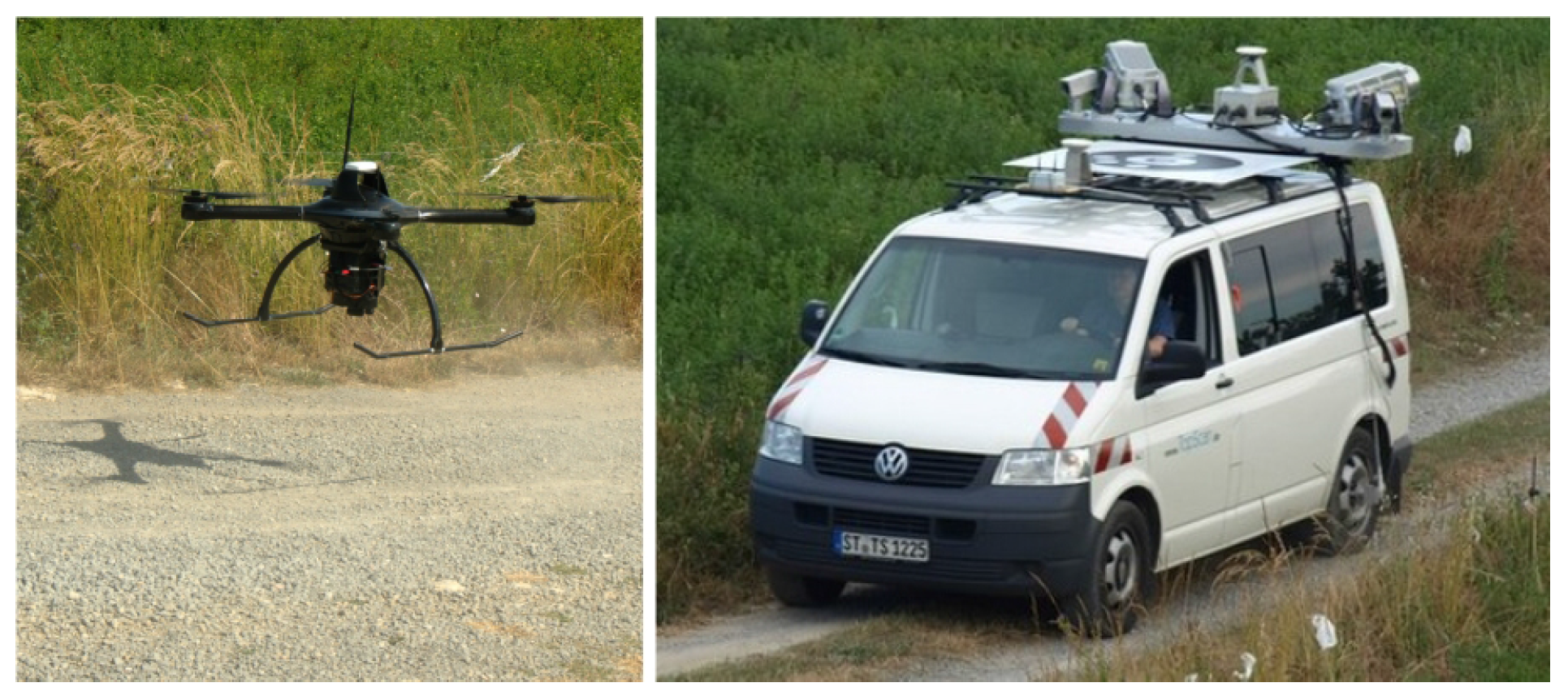
Figure 1, the UA and TV carriers used are the Spyro-4 quadcopter, by UAVision (Torres Vedras, Portugal), and a van operated by TopScan GmbH (Rheine, Germany). The van carries an Lynx TMMS, by Teledyne Optech Inc. (Toronto, Canada), which includes a pair of laser scanners and an INS/GNSS navigation system, the POS-LV 420 system by Applanix, which is a hybrid Inertial Navigation System (INS) and a GNSS navigation system, both for post-processing and real-time. In the Supplementary Materials section, we provide links to the test campaign brochure and video report.

3.1. System Characteristics and Mission Design

Table 1 describes the mission design aspects of the reported test campaign, focusing on the payload sub-systems and the fundamental mission parameters.
From the various flights, for this article, we selected one covering a 2.3 km rural road corridor. The flying direction was mainly northwards, including a 180-degree turn at the beginning of the corridor and some positive bearing clockwise turns during the flight. The flying height ranged between 80 and 90 m above ground level, which results in a height variation of around 11% of the mean height value. The configured, nominal image forward overlap was 80%, yielding an approximate base-to-height ratio of 0.156. The selected forward overlap value is a safe compromise to guarantee the minimum geometrical strength in presence of wind bursts, large terrain variations, and other conditions. The used camera was a Sony NEX-5R with a 20 mm camera constant lens, duly synchronized with the GNSS receiver. A total number of 149 images were recorded with an approximate ground sampling distance (GSD) of 2 cm. A GNSS geodetic-grade triple-frequency receiver recording code and phase measurements, located at a reference point of known coordinates (mm-level accuracy) within the test area, was available.
Since the current acquired data does not enjoy the full measurement configuration for mapKITE, we aimed at demonstrating the potential of our contribution with specific but sufficiently representative configurations, instead of exhaustively testing multiple configurations. Therefore, we report on the orientation results of two of them: a typical mapKITE configuration (MC) and a “conventional” configuration (CC). In the MC configuration, we used KGCPs and two GCPs at the respective ends of the corridor strip. In contrast, for the CC configuration, we used a more dense ground control configuration. Finally, we generate a full corridor (FC) by combining all GCPs and KGCPs to serve as a reference for calibration parameters (see Section 3.4 for more details on the MC, CC and FC blocks). Note that an advantage of mapKITE is the use of KGCPs, which allows corridors to be mapped with single-strip blocks (just forward overlap) as opposed to conventional multiple-strip blocks (forward and side overlap) for corridors. We are aware that single-strip configurations for conventional corridor mapping are not frequent and, therefore, that comparing the performance of mapKITE to conventional corridor mapping may be somewhat unfair, as we might have selected configurations with multiple strips and side overlap. However, we choose both CC and MC corridors to be single-strip, as it serves the purpose of understanding the impact of using KGCPs.

3.2. Observations and Parameters for Sensor Orientation and Calibration

Typically, a mapKITE mission produces the same set of measurements as the combination of a conventional aerial survey and a TMMS one, plus the KGCPs and their measurements of the images. We concentrate here on the aerial survey measurements (GCPs, aerial control, image coordinates) and on the ground coordinates and photogrammetric measurements of the KGCPs. We also detail the selected parameter configuration.
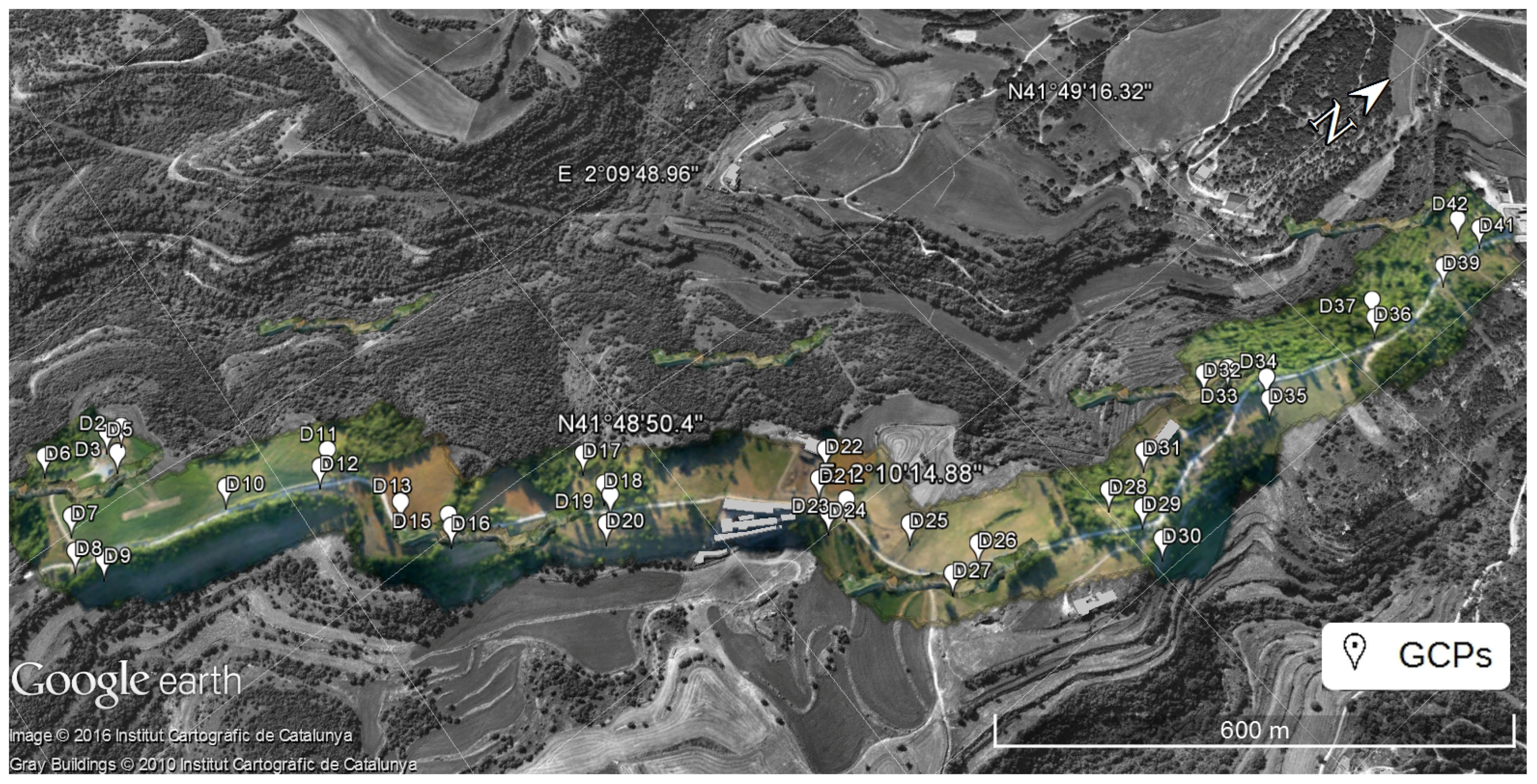
Ground control and check points. A network of thirty-seven targeted points was surveyed along the segment with cm-level precision, distributed in groups of two, three or four points and with groups separated evenly along the corridor. Depending on the block configuration, these points may play the role of GCPs or of Ground Check Points (GChPs). Their geometric distribution is depicted in Figure 2.
GNSS aerial control. The aircraft trajectory was obtained from the aircraft and ground reference GNSS receivers with carrier-phase differential post-processing techniques, thus delivering cm-level accurate results. The actual observables for sensor orientation are the GNSS antenna positions at the image acquisition epochs, which are extracted from the event recording messages in the receiver file. We note that camera flash-based synchronization can be achieved at the ms-level [6].
Kinematic ground control points. Similarly to the aerial control, a trajectory was obtained by post-processing the observables of the previously described Applanix POS LV 420 system, mounted on the TMMS, again using the ground reference GNSS station and differential carrier-phase processing. Once the trajectory was available, the KGCPs were extracted at the image acquisition epochs.
Tie point photogrammetric measurements. Image keypoints were extracted from the 149 images and matched among overlapping images. We used an average of 344 extracted points per image, yielding an amount of 6912 tie points. Imposing a minimum of three-fold image observation per tie point, the total number of photogrammetric observations summed up to 24,712. The photogrammetric measurements were extracted using Agisoft’s Photoscan Professional [13]. Additionally, all GCPs were manually measured for the images.
Photogrammetric measurements of KGCPs. Pointing photogrammetric measurements of the KGCPs targets were performed automatically with tools developed by the Geodetic Engineering Laboratory (TOPO) group at the École Polytechnique Fédéral de Lausanne (EPFL). The target concept and developed tools are described in [12] (the scale measurement of the KGCPs according to the mapKITE concept is currently being developed, and, therefore, no measurements of scale were available for the reported test).
Table 2 further complements the information on measurements with their assumed and/or estimated precision. Realistic measurement precision assignment is as difficult as it is important for quality image orientation and calibration. An unbalanced relative weight assignment in ISO results in suboptimal results. For the large observation subsets, like the photogrammetric measurements, we confirmed the goodness of our precision estimates with variance-component estimation techniques [14]. For the smaller data subsets like GCPs and KGCPs we slightly downweighted the output GNSS processing precision estimates according to our experience.
The parameter sets estimated for this mapKITE block are those from standard aerial ISO blocks given the described set-up and sub-systems (exterior and interior orientation, Conrady-Brown calibration, and tie point parameters) with the exception of GNSS aerial control shift correction parameters.
In practice, mapKITE shall work with much longer distances with respect to GNSS reference stations or with kinematic PPP GNSS techniques. Furthermore, in practice, this strategy would lead to the introduction of GNSS shift parameters for both aerial control and KGCPs. However, in the block configurations investigated in this article and due to the propitious availability of a close GNSS reference station, no GNSS shift parameters were estimated. In turn, the particular geometry of the block (strong pitch variations—up to 10 degrees—due to forward acceleration and deceleration of the aircraft, large roll variations, block irregular shape and relatively high terrain variations), together with the absence of GNSS shift parameters, allowed us to perform image self-calibration (interior orientation and Conrady–Brown parameters) even in the absence of image calibration manoeuvres.
According to our experience, image self-calibration for single-strip blocks may perform poorly or lead to numerical stability problems. This is especially the case for smaller scale blocks flown with manned aircraft, in which the ratio between terrain variations and flying height is very small. Again, and for the current block, this was not our case.
The mathematical models used were the conventional position-only GNSS aerial control and colinearity equations.

3.3. Software

The photogrammetric tie point measurements were generated using Agisoft’s Photoscan Professional [13]. All mathematical models involved in the current orientation and calibration approach were implemented in the airVISION model toolbox of GeoNumerics’ GENA adjustment platform [15]. The results described in this article were also generated with the GENA and airVISION in tandem. Finally, as mentioned, the automatic photogrammetric measurement of the KGCPs target coordinates was performed with software by the TOPO group (Lausanne, Switzerland) [12].

3.4. Definition of the Validation Framework: Conventional Corridor versus mapKITE Corridor

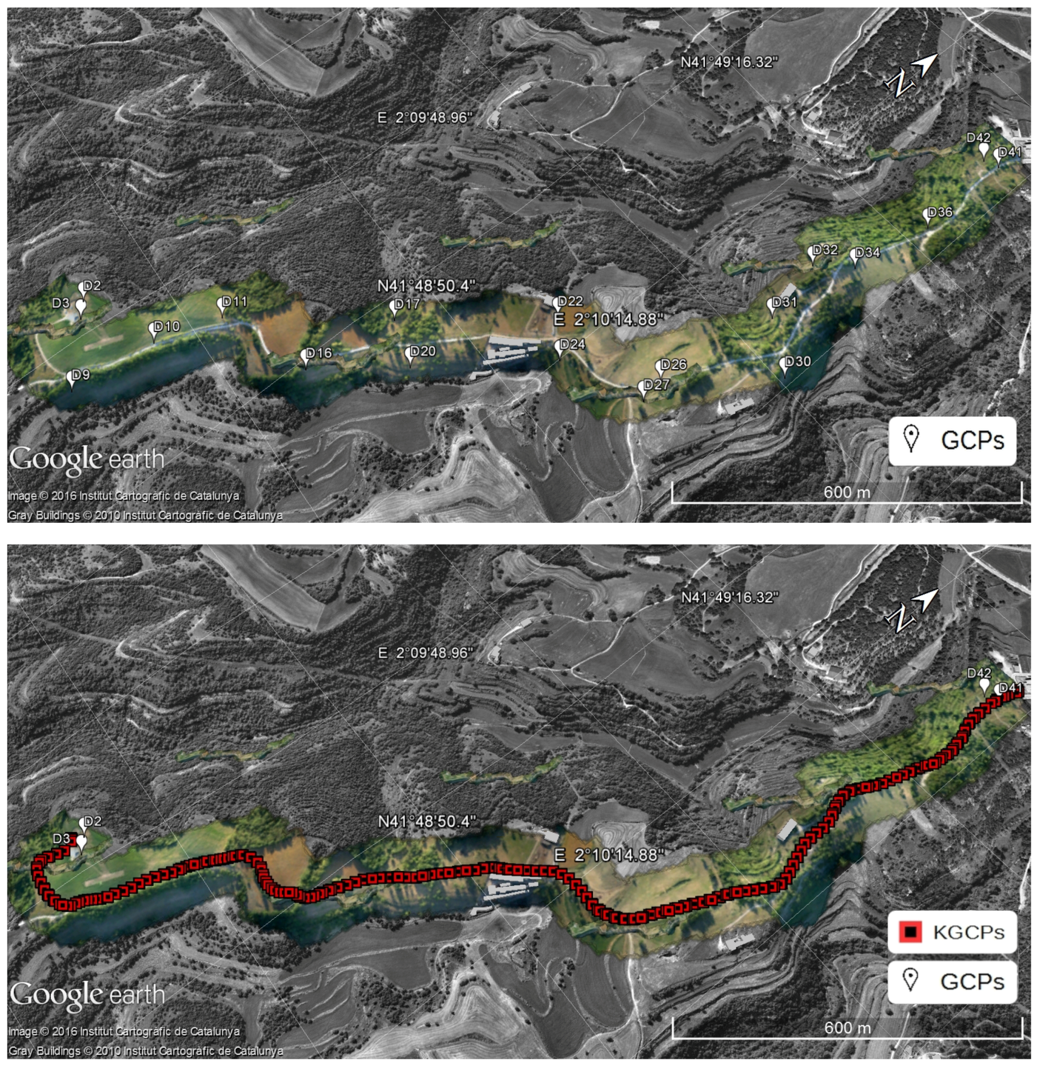
For the validation and analysis of the mapKITE concept and method, we propose a quality assessment method based on three block configurations: CC and MC, as introduced in Section 3.1, plus FC (full configuration). The FC configuration combines in an ISO adjustment all available ground control information, i.e., all KGCPs and the full set of thirty-seven GCPs. The purpose of the FC configuration is to produce the best reference estimate of the airborne camera calibration parameters to evaluate the sensitivity and validity of calibration of the CC and, particularly, of the MC configuration.
Figure 3 depicts the distribution of GCPs and KGCPs. We provide some additional descriptions hereafter.
The CC consists of a mission executed following the previously described configuration, and using an evenly distributed set of 19 GCPs from the total set depicted in Figure 2 —more precisely, D02, D03, D09, D10, D11, D16, D17, D20, D22, D24, D26, D27, D30, D31, D32, D34, D36, D41 and D42—with no KGCPs. The remaining 18 surveyed ground points are used as GChPs and constitute the basis of the accuracy performance analysis. It goes without saying that there are no KGCPs in the CC case. The election of GCPs is not arbitrary and responds to what would be a “typical configuration” of a corridor mapping mission according to our experience. Admittedly, there may be as many “typical configurations” as photogrammetrists.
On the other hand, the MC configuration is defined as the same corridor mission but using 136 KGCPs, their photogrammetric measurements, and just four GCPs—that is, D02, D03, D41 and D42—located at the ends of the strip. The number of KGCPs measurements is slightly lower than the number of images, that is, not every image benefits from kinematic control. This is a normal situation in mapKITE missions, in which partial or total occlusion of the land vehicle target by shadows of nearby objects (mainly trees) or lack of visibility within the camera field-of-view happen. For this case, the index of valid KGCP measurements (that is, the ratio of number of valid KGCP photogrammetric measurements over total number of images) is 91.2%. For comparative analysis purposes, the GChP set is the same as in the CC case.
The quality assessment of mapKITE, i.e., of the MC configuration is based on the usual statistics of errors at GChPs—maximum, minimum, mean, empirical standard deviation and root mean square (RMS) errors. Using the mean GSD value (≈2 cm), we also provide RMS figures in pixel (px) units (Table 3).
Finally, we also investigate the reliability of camera self-calibration for the CC and MC configurations by comparing the estimated calibration parameters with their FC counterparts (Table 4).

3.5. Results and Discussion

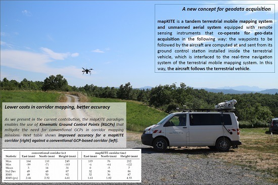
Table 3 compiles the accuracy results obtained with the two corridor configurations CC and MC. By using KGCPs and a pair of GCPs at the beginning and end of the mission, we obtain slightly better results than the conventional configuration with many more GCPs. 
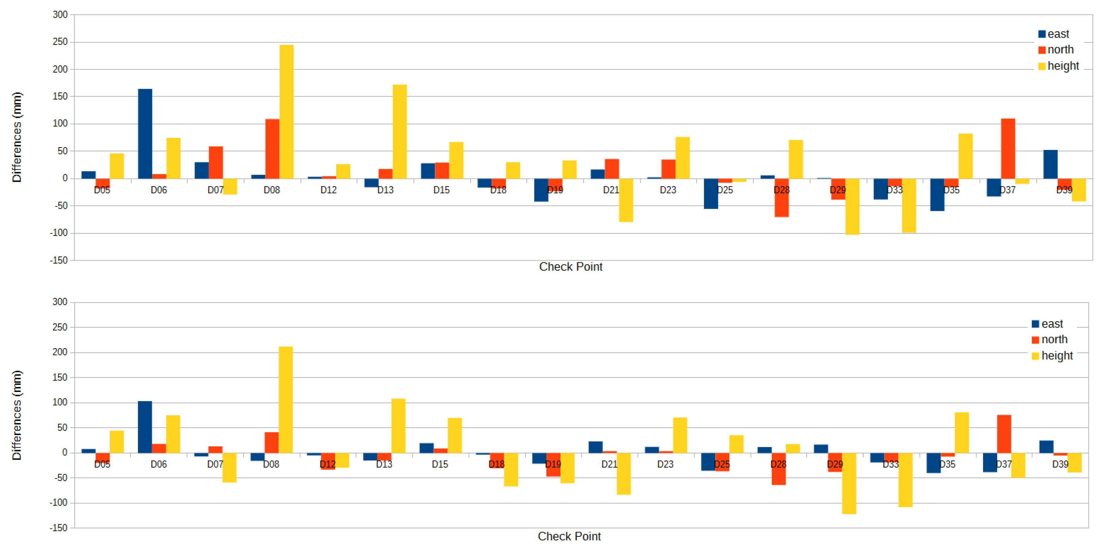
Figure 4 depicts the differences in check point coordinates per each point. The results are almost self-explanatory; as for the given configurations, mapKITE performs better than the conventional procedure in all respects: global systematic errors and dispersion. In the mapKITE case, it is remarkable that even in the absence of point-and-scale photogrammetric measurements, the height accuracy is significantly better than in the CC case. A KGCP is only observed in one image and its influence on the horizontal accuracy is, accordingly, higher than in the vertical accuracy if a measure of scale is not available. However, the combination of the accurate GNSS-based aerial control, of the accurate KGCPs and of a correct self-calibration performed beyond our expectations. Of course, one could argue that the MC configuration performs better than the CC performance depending on the number of GCPs used in the CC block and that we may be comparing two different things. Following this line of thinking, we may produce a CC configuration with comparable or superior results than the MC configuration, however, at a much higher cost. On the other hand, once the point-and-scale measurements will be used, the vertical accuracy of the mapKITE blocks shall further improve.
Table 4 illustrates the performance of camera self-calibration. As we do not have an absolute reference for self-calibration, a preliminary assessment can be done by comparing the calibration parameters of the CC and MC blocks with the FC one. The table is self-explanatory and reveals that there are no significant differences between the three estimate sets, even with identical precision estimates for radial distortions. We note that all calibration parameters are significant. Again, this is a remarkable result for mapKITE, as we had no previous experience with mapKITE blocks and expect the geometric strength of the blocks to improve with point-and-scale measurements.
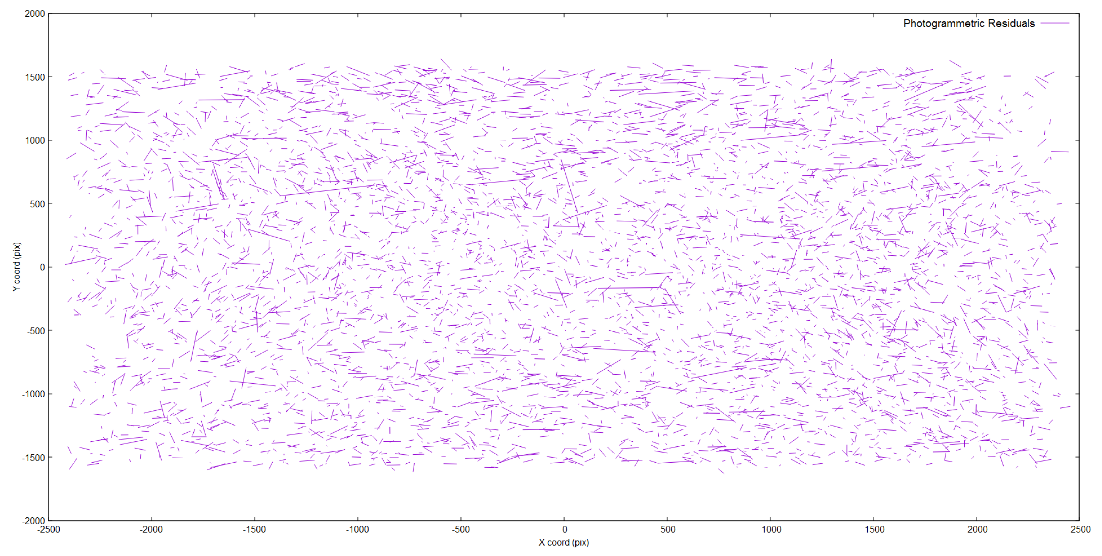
Figure 5 shows the distribution of photogrammetric residuals of the tie point measurements in the MC case. Although we observe a few large residuals, we observe no dominant systematic effect, which provides one more measure of the quality of the self-calibration in this block.
Figure 6 describes the error ellipses describing the associated precision to each GChP estimation in the mapKITE corridor. Naturally, GChPs located at the borders of the mostly concave corridor are determined with a lower precision.
A final assessment item on the quality and reliability of the self-calibration parameters is the analysis of parameter correlations. For the Conrady–Brown (CB) parameters, Exterior Orientation (EO) parameters and Interior Orientation (IO) parameters, we extracted parameter correlations from the parameter covariance matrix for the following combinations: CB–IO, EO–EO, IO–IO and EO–IO. We do not include parameter correlation tables since all correlations for the three configurations were bounded well away from the critical values −1, 1.

4. Conclusions

We have reviewed the mapKITE concept and method for corridor mapping with tandem terrestrial and unmanned aerial mapping systems, and provided preliminary results that confirmed the conclusions of earlier simulation analyses [8]. The results refer to the quality of the orientation and calibration of the unmanned aircraft images through the analysis of the ground point determination accuracy estimated with check points. These preliminary results were derived with data collected for basic verification and validation purposes according to simplified mapKITE acquisition (no calibration manoeuvres) and processing (no measurements of KGCP scale) concepts. In spite of these limitations, we achieved accuracies significantly better than those of conventional ISO techniques for corridors with almost no ground control points μ E , N 1.7 px and μ h 4.3 px). An analysis of the adjustment results shows that the camera interior orientation and the Conrady–Brown calibration parameters were correctly estimated without dangerous correlations. The results are encouraging as have been obtained with a simplified mapKITE mission configuration concept and without the use of scale measurements. A second mapKITE campaign is planned for March 2017 where the full mapKITE data acquisition and processing methods will be rehearsed. In the planned campaign, longer distances to GNSS reference stations and kinematic PPP GNSS processing techniques will also be investigated.
We note that the on-going deployment of the European Union Galileo and the Chinese Beidou GNSS, together with the existing GPS and Russian Global Navigation Satellite System (GLONASS), will result in some 100 GNSS satellites by 2020.From these, half will be broadcasting new wideband signals with improved multipath mitigation and more precise code-based ranging. The new GNSS scenario clearly plays in favor of mapKITE.
Our current, preliminary quality figures seem to indicate that results can only improve in the next campaign and in the coming years.

Supplementary Materials

Additional available materials report about the concept and results from the presented test campaign, such as a Test Campaign Video (http://vimeo.com/181634599) and Report Brochure in PDF format (http://mapkite.com/images/mapKITE_files/mapKITE_first-demonstration_v0-0.pdf).

Acknowledgments

The research, development and test campaign explained in this paper has been funded by the European Community Horizon 2020 Programme under Grant No. 641518 (project mapKITE, www.mapkite.com) managed by the European GNSS Agency (GSA). The authors want to thank Javad for the contributions to the payload elements in mapKITE.

Author Contributions

All authors have contributed to the research, development, data collection, processing and presentation of results for the current paper.

Conflicts of Interest

The authors declare no conflict of interest.

References

  1. Colomina, I.; Molina, P. Unmanned Aerial Systems for Photogrammetry and Remote Sensing: A review. ISPRS J. 2014, 92, 79–97. [Google Scholar] [CrossRef]
  2. Gruen, A.; Huang, X.; Qin, R.; Du, T.; Fang, W.; Boavida, J.; Oliveria, A. Joint Processing of UAV Imagery and Terrestrial Mobile Mapping System Data for Very High Resolution City Modeling. Int. Arch. Photogramm. Remote Sens. Spat. Inf. Sci. 2013, XL-1/W2, 175–182. [Google Scholar] [CrossRef]
  3. Mayer, H. From Orientation to Functional Modeling for Terrestrial and UAV Images. In 55th Photogrammetric Week; Wichmann/VDE Verlag: Berlin/Offenbach, Germany, 2015; pp. 165–174. [Google Scholar]
  4. Leslar, M. Integrating Terrestrial LiDAR with Point Clouds Created from Unmanned Aerial Vehicle Imagery. Int. Arch. Photogramm. Remote Sens. Spat. Inf. Sci. 2015, XL-1/W4, 97–101. [Google Scholar] [CrossRef]
  5. Sensefly. Drones vs. Traditional Instruments: Corridor Mapping in Turkey. 2015. Available online: https://goo.gl/4rLmtZ (accessed on 6 January 2017).
  6. Rehak, M.; Skaloud, J. Fixed-Wing Micro Aerial Vehicle for Accurate Corridor Mapping. Int. Arch. Photogramm. Remote Sens. Spat. Inf. Sci. 2015, II-1/W1, 23–31. [Google Scholar] [CrossRef]
  7. Blázquez, M.; Colomina, I. Performance Analysis of Fast AT for Corridor Aerial Mapping. Int. Arch. Photogramm. Remote Sens. Spat. Inf. Sci. 2012, XXXIX-B1, 97–102. [Google Scholar] [CrossRef]
  8. Molina, P.; Blázquez, M.; Sastre, J.; Colomina, I. Precision Analysis of Point-and-Scale Photogrammetric Measurements for Corridor Mapping: Preliminary Results. Int. Arch. Photogramm. Remote Sens. Spat. Inf. Sci. 2016, 40, 85–90. [Google Scholar] [CrossRef]
  9. Molina, P.; Blázquez, M.; Sastre, J.; Colomina, I. A Method for Simultaneous Aerial and Terrestrial Geodata Acquistion for Corridor Mapping. Int. Arch. Photogramm. Remote Sens. Spat. Inf. Sci. 2015, XL-1/W4, 227–232. [Google Scholar] [CrossRef]
  10. Molina, P.; Blázquez, M.; Sastre, J.; Colomina, I. mapKITE: A New Paradigm for Simultaneous Aerial and Terrestrial Geodata Acquisition and Mapping. Int. Arch. Photogramm. Remote Sens. Spat. Inf. Sci. 2016, XLI-B1, 957–962. [Google Scholar] [CrossRef]
  11. Fact Sheet—Small Unmanned Aircraft Regulations (Part 107) —Federal Aviation Administration, United States. Available online: https://goo.gl/E5aGMv (accessed on 6 January 2017).
  12. Cucci, D.A. Accurate Optical Target Pose Determination For Applications in Aerial Photogrammetry. Int. Arch. Photogramm. Remote Sens. Spat. Inf. Sci. 2016, III-3, 257–262. [Google Scholar]
  13. Agisoft. Photoscan Professional. 2016. Available online: http://www.agisoft.com/ (accessed on 6 January 2017).
  14. Förstner, W. Ein Verfahren zur Schätzung von Varianz- und Kovarianzkomponenten. Allgemeine Vermessungs Nachrichten 1979, 11–12, 446–453. [Google Scholar]
  15. Colomina, I.; Blázquez, M.; Navarro, J.; Sastre, J. The Need and Keys for a New Generation Network Adjustment Software. Int. Arch. Photogramm. Remote Sens. Spat. Inf. Sci. 2012, XXXIX-B1, 303–308. [Google Scholar] [CrossRef]
Figure 1. Unmanned aircraft and terrestrial vehicle used in the mapKITE Test Campaign in June 2016. The optical target is seen on the top of the van.
Remotesensing 09 00060 g001
Figure 2. Distribution of ground control points along the test corridor.
Remotesensing 09 00060 g002
Figure 3. Ground control configuration for the analysed corridors: top, GCP set for conventional corridor; bottom, the mapKITE corridor with two GCPs at the beginning and two more at the end and one KGCP per image.
Remotesensing 09 00060 g003
Figure 4. Errors at each GChP for the conventional corridor (CC) (top) and the mapKITE corridor (MC) (bottom).
Remotesensing 09 00060 g004
Figure 5. Photogrammetric residuals of tie points for the MC configuration.
Remotesensing 09 00060 g005
Figure 6. Scaled error ellipses (planimetry, cyan; height, purple) of GChPs in the MC configuration. We use a map-projected Coordinate Reference Frame (CRF) using UTM 31(N) easting–northing coordinates.
Remotesensing 09 00060 g006
Table 1. Mission design parameters.
ParameterName or ValueUnits
Equipment (UA camera)NEX-5R (Sony)
Equipment (TV navigation)POS-LV 420 (Applanix)
Equipment (UA navigation)GNSS receiver TRE-3 (Javad)
Equipment (GNSS base station)GNSS receiver TR-G2T Alpha (Javad)
Sensor size23.5 × 15.6mm
4920 × 3276px
Pixel size4.8μm
Camera constant20mm
Corridor length2.3km
Corridor modalitysingle-strip
Corridor flying height80–90m
Average base-to-height ratio0.156
No. of bases149
Average Ground Sampling Distance1.92–2.16cm
Forward Overlap≈80%
Calibration manoeuvresNone
Table 2. Standard deviation (σ) of measurements collected in the mapKITE campaign. We use Easting, Northing, and Height ( E , N , h ) for position and image coordinates ( x , y ) for photogrammetric measurements.
ObservablesPrecisionUnits
GCP
  - σ E , N , h 1.5cm
GNSS aerial control
  - σ E , N 2cm
  - σ h 5cm
Kinematic GCP (KGCP)
  - σ E , N 2cm
  - σ h 4cm
Tie Point Image Coordinates
  - σ x , y 4μm
0.83px
Pointing coordinates of GCP
  - σ x , y 4μm
0.83px
Pointing coordinates of KGCP
  - σ x , y 2.4μm
0.5px
Table 3. Accuracy of sensor orientation for the conventional and mapKITE corridors: statistics of the difference between estimated and reference coordinates of check points.
StatisticConventional Corridor (CC)mapKITE Corridor (MC)
East (mm)North (mm)Height (mm)East (mm)North (mm)Height (mm)
Max16411024510376212
Min−59−71−103−4−64−122
Mean314310−57
Std Dev494887323686
RMS495092323687
RMS (px)2.462.524.611.611.824.33
Table 4. Expectation ( e ) and standard deviation ( σ ) of self-calibration estimated parameters for the conventional corridor (CC), mapKITE corridor (MC) and full corridor (FC).
Item δ f δ x 0 δ y 0 k 1 k 2 k 3 p 1 p 2
Unitspxpxpxm−2m−4m−6m−1m−1
CC (e)4268.227−11.32343.033−384.87979.6541.4324.895 × 10−36.202 × 10⁻²
(σ)0.6900.6130.6641.3891.5940.5391.756 × 10−31.514 × 10⁻³
MC (e)4267.331−10.81542.678−384.77279.5651.4614.897 × 10−36.076 × 10⁻²
(σ)1.0380.6580.6771.3891.5940.5391.772 × 10−31.480 × 10⁻³
FC (e)4268.036−11.28243.645−385.20680.2791.1954.397 × 10−36.039 × 10⁻²
(σ)0.5130.5630.6411.3901.5940.5391.711 × 10−31.464 × 10⁻³
The radial distortion parameters k 1 , k 2 , k 3 are internally scaled for numerical stability purposes, and thus may not be directly comparable to other Conrady-Brown implementations.

