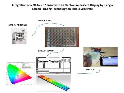
Integration of a 2D Touch Sensor with an Electroluminescent Display by Using a Screen-Printing Technology on Textile Substrate

 ,
,
Abstract
:
1. Introduction
2. Materials and Methods
2.1. Device Architecture Development
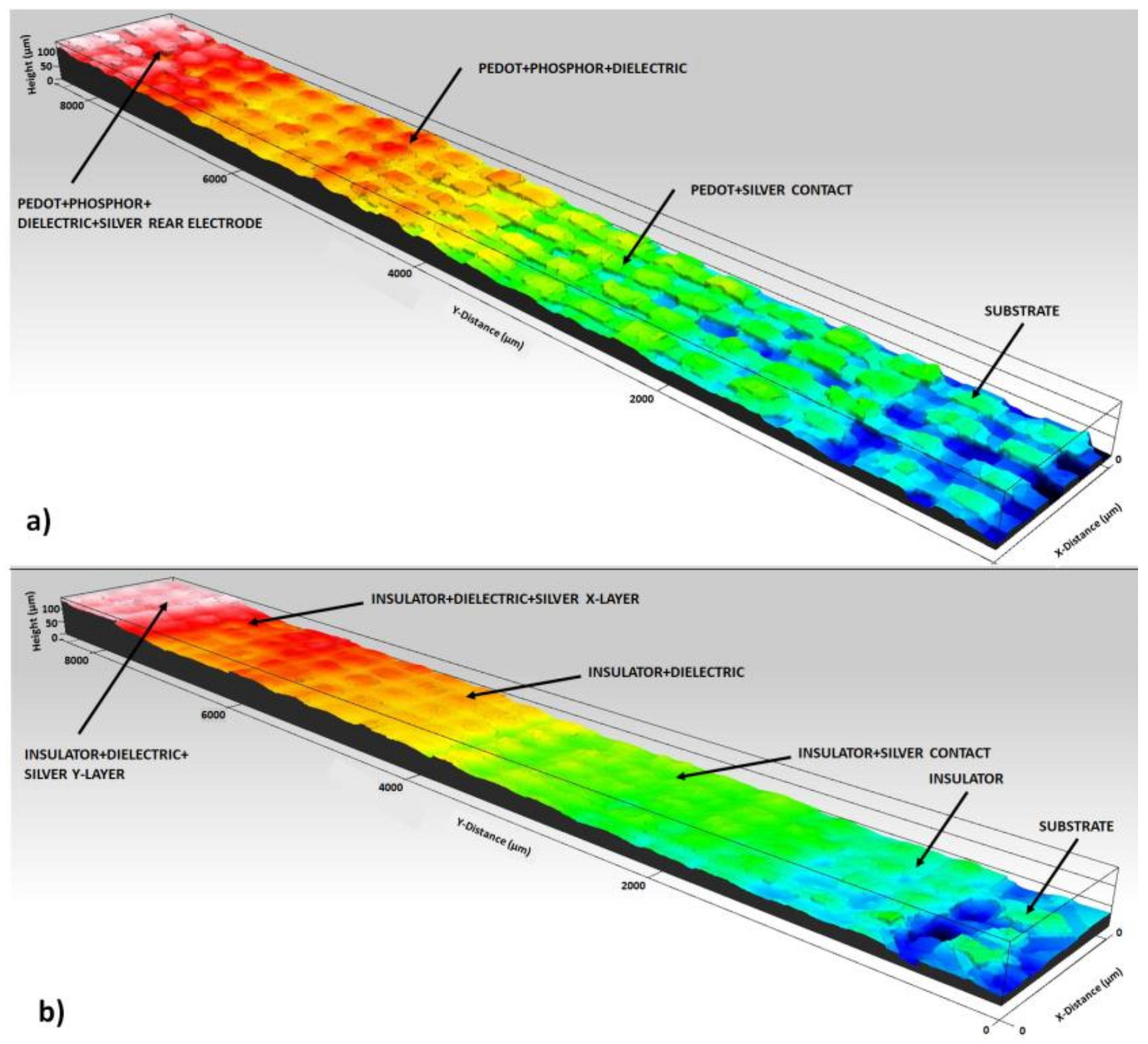
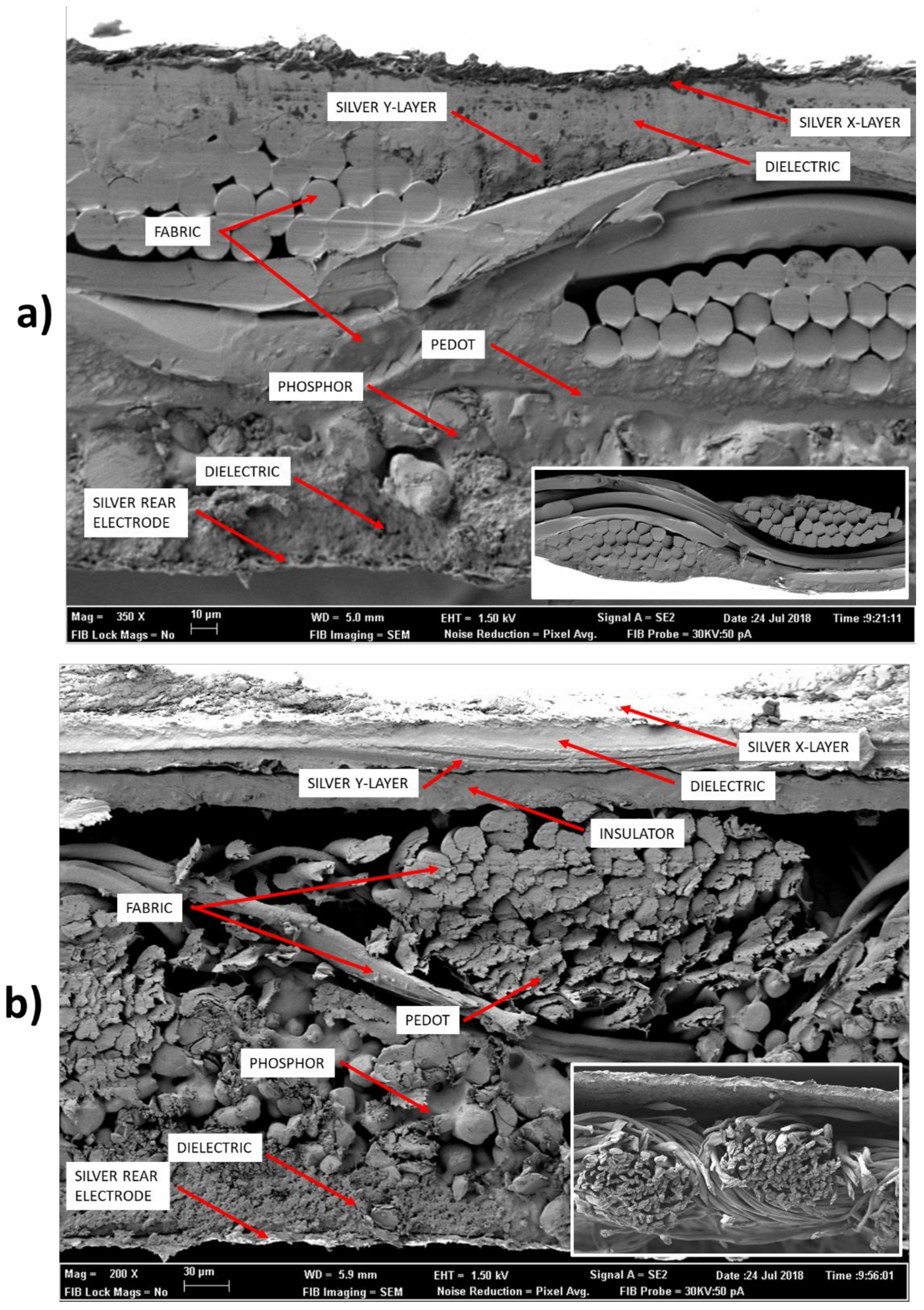
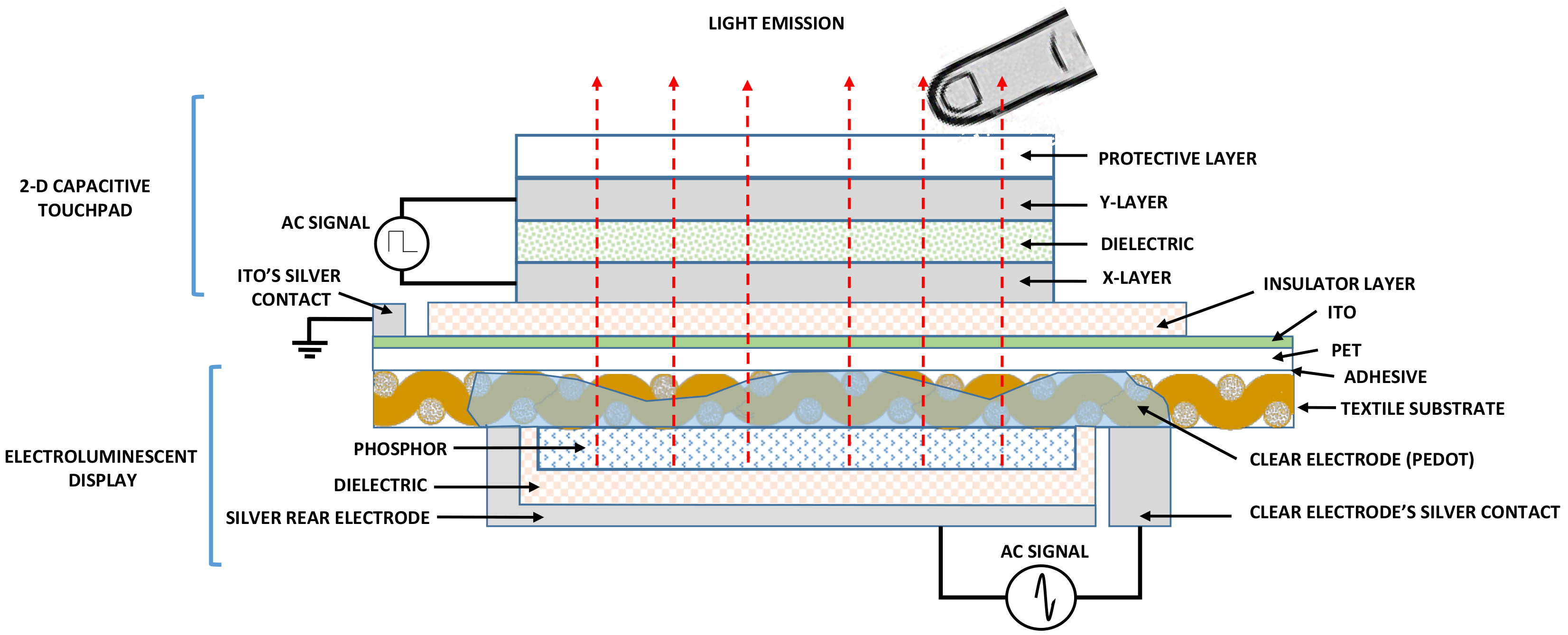
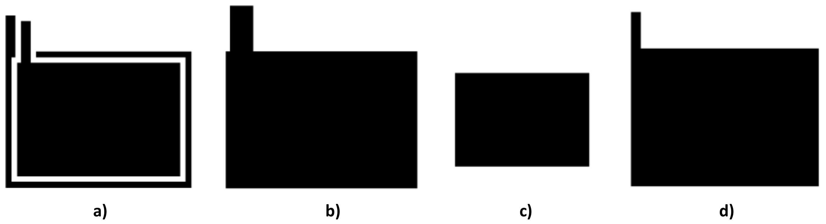
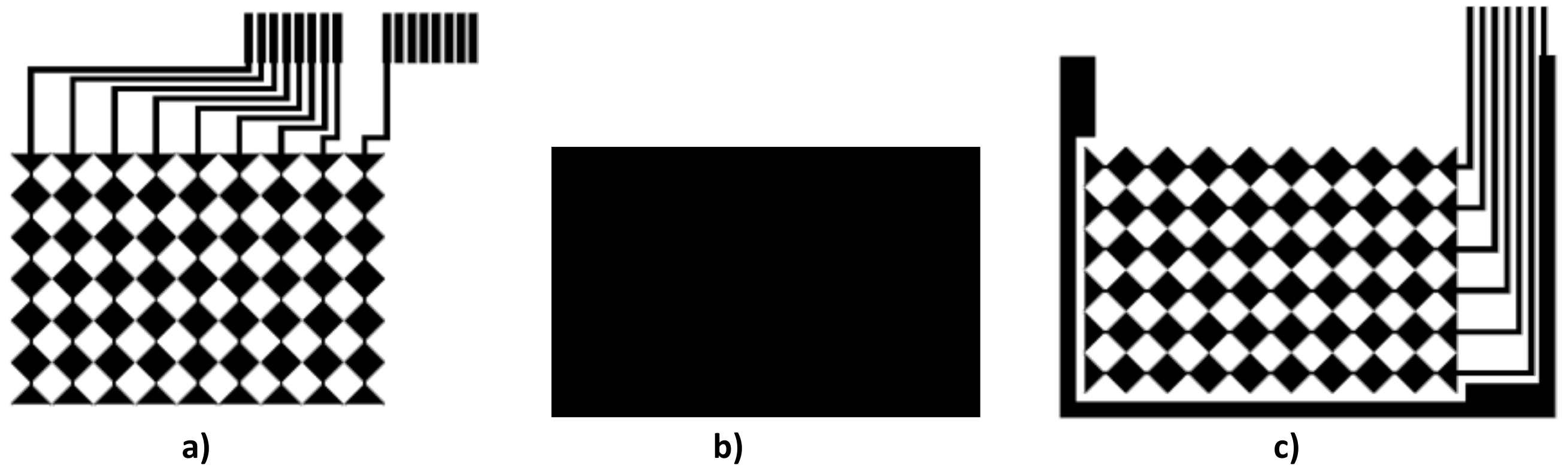
- Using the fabric as a base, silk-screen printing is done, first corresponding to the ELD and next, corresponding to the 2D sensor. An insulator must be inserted between the two layers (Figure 1a).
- Using the own fabric as part of the emitting electrode, the different layers of the electroluminescent are printed in the lower part of the fabric and the 2D sensor in the upper part. This upper part is conveniently insulated in those cases in which the conductive material of the emitting electrode is completely embedded in the fabric (Figure 1b).
2.1.1. Electroluminescent Display Development
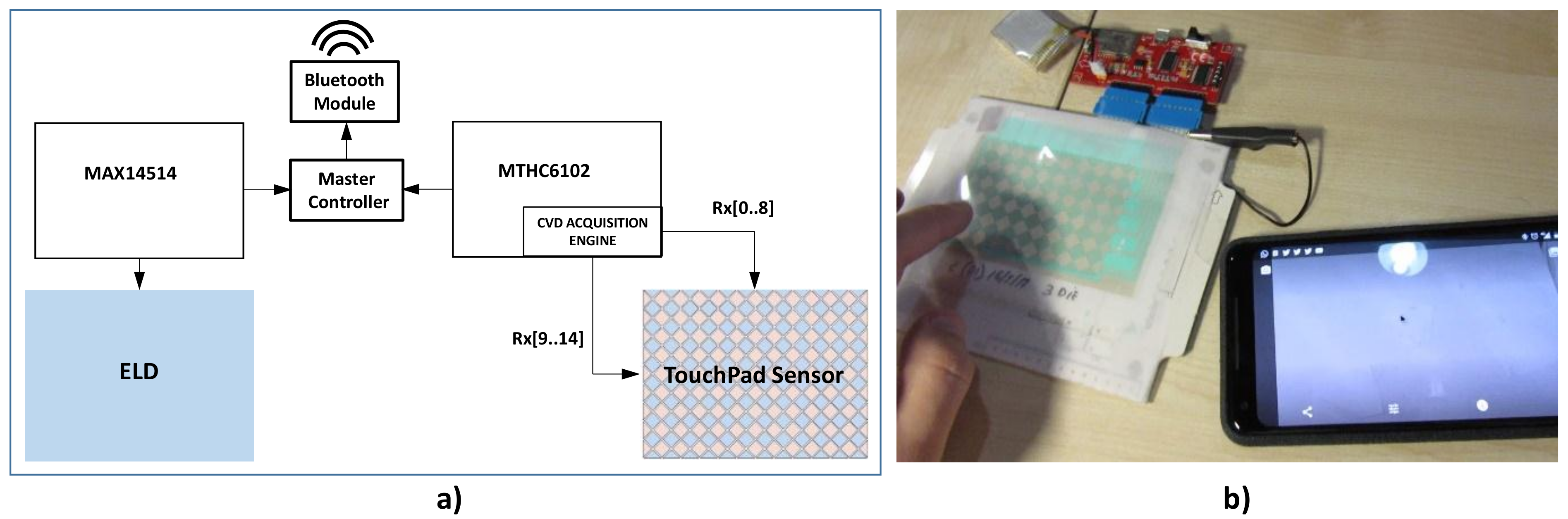
2.2. Electronic Systems Development
2.2.1. ELD Electronic Block
2.2.2. 2D Touchpad Electronic Block
3. Results and Discussion
3.1. Physical Parameters
3.2. Electroluminescent Display Results
3.3. 2D Touchpad Results
3.4. Final Design
4. Conclusions
Author Contributions
Funding
Conflicts of Interest
Appendix A


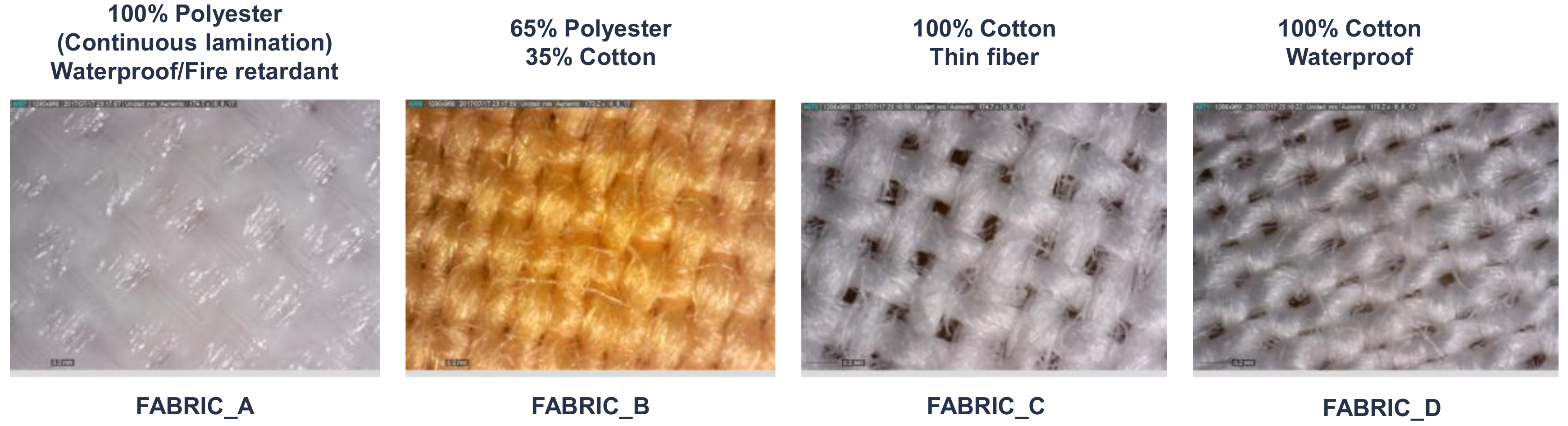
| Fabric | Weft Density (Thread/cm) | Warp Density (Thread/cm) | Ligament | Grammage (g/m2) | Weft Material | Warp Material | Thickness (µm) |
|---|---|---|---|---|---|---|---|
| (A) Mediatex | 25 | 40 | Taffeta | 115 | Polyester | Polyester | 110 |
| (B) 65% Pol/35% Cot | 30 | 46 | Taffeta | 110 | Cotton | Polyester | 200 |
| (C) 100% Cotton | 30 | 30 | Taffeta | 120 | Cotton | Cotton | 190 |
| (D) 100% Cotton Waterproof | 34 | 45 | Taffeta | 120 | Cotton | Cotton | 130 |
| pe | Substrate | Clear Conductor | lux | CIE 1931 Standard | Light Trans | |||
|---|---|---|---|---|---|---|---|---|
| x | y | z | Dominant | |||||
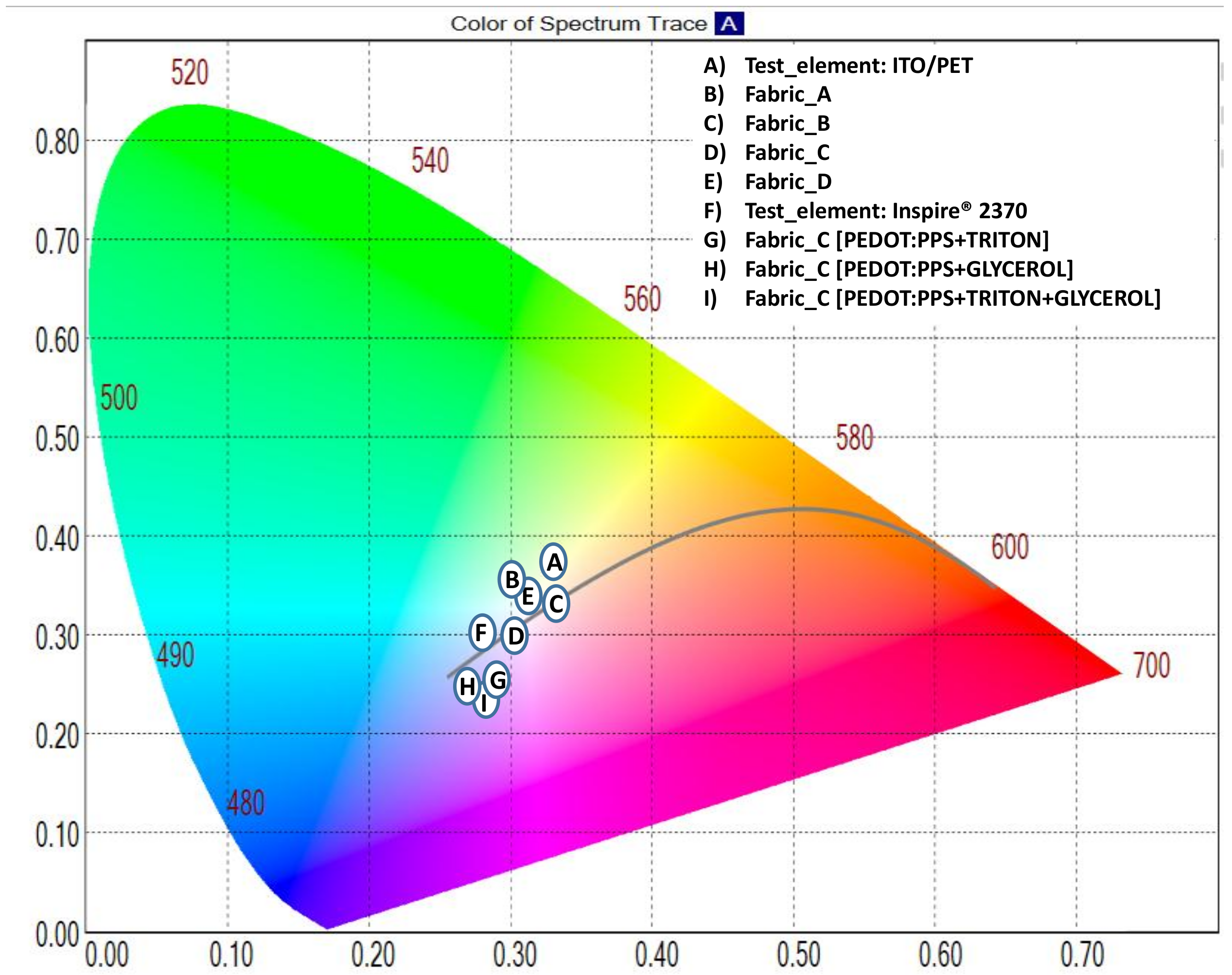
| A | PET | ITO | 217 | 0.3294 | 0.3745 | 0.2961 | 549.59 | 79% |
| B | Fabric_A | PEDOT:PSS | 74.1 | 0.3195 | 0.3553 | 0.3253 | 514.31 | 27% |
| C | Fabric_B | PEDOT:PSS | 11.3 | 0.3479 | 0.3428 | 0.3093 | 583.37 | 14% |
| D | Fabric_C | PEDOT:PSS | 11.2 | 0.3059 | 0.3112 | 0.3829 | 480.36 | 32% |
| E | Fabric_D | PEDOT:PSS | 29.2 | 0.3084 | 0.3374 | 0.3542 | 493.81 | 30% |
| F | Inspire 2370 | PEDOT:PSS | 170 | 0.2821 | 0.3328 | 0.3851 | 491.58 | 49% |
| G | Fabric_C | PEDOT:PSS + TRITON | 15 | 0.2764 | 0.2503 | 0.4733 | 465.84 | 33% |
| H | Fabric_C | PEDOT:PSS + GLYCEROL | 14 | 0.2701 | 0.2529 | 0.4770 | 471.12 | 32% |
| I | Fabric_C | PEDOT:PSS + GLYCEROL + TRITON | 10 | 0.2813 | 0.2470 | 0.4717 | 457.22 | 33% |
References
- Blattner, A.; Bengler, K.; Hamberger, W.; Schnieder, S. Comparison of in-car touchpads with adaptive haptic feedback. In Proceedings of the 2012 IEEE International Workshop on Haptic Audio Visual Environments and Games, Munich, Germany, 8–9 October 2012. [Google Scholar]
- Ishizuka, H.; Hatada, R.; Cortes, C.; Miki, N. Development of a fully flexible sheet-type tactile display based on electrovibration stimulus. Micromachines 2018, 9, 230. [Google Scholar] [CrossRef]
- Hoggan, E.; Crossan, A.; Brewster, S.; Kaaresoja, T. Audio or Tactile Feedback: Which Modality When? In Proceedings of the SIGCHI Conference on Human Factors in Computing Systems, Boston, MA, USA, 4–9 April 2009. [Google Scholar]
- Chang, A.; O’Sullivan, C. Audio-haptic Feedback in Mobile Phones. In Proceedings of the CHI ’05 Extended Abstracts on Human Factors in Computing, Portland, OR, USA, 2–7 April 2005. [Google Scholar]
- Jung, J.; Youn, E.; Lee, G. PinPad: Touchpad Interaction with Fast and High-Resolution Tactile Output. In Proceedings of the 2017 CHI Conference on Human Factors in Computing Systems, Denver, CO, USA, 6–11 May 2017. [Google Scholar]
- Ferri, J.; Moreno, J.; Martinez, G.; Lidón-Roger, J.V.; Garcia-Breijo, E. Wearable Textile 2D Touchpad Sensor Based on Screen-Printing Technology. Materials 2017, 10, 1450. [Google Scholar] [CrossRef] [PubMed]
- Bhalla, M.R.; Bhalla, A.V. Comparative Study of Various Touchscreen Technologies. Int. J. Comput. Appl. 2010, 6, 12–18. [Google Scholar] [CrossRef] [Green Version]
- Walker, G. A review of technologies for sensing contact location on the surface of a display. J. Soc. Inf. Disp. 2012, 20, 413–440. [Google Scholar] [CrossRef]
- Pedersen, H.C.; Jakobsen, M.L.; Hanson, S.G.; Mosgaard, M.; Iversen, T.; Korsgaard, J. Optical touch screen based on waveguide sensing. Appl. Phys. Lett. 2011, 99, 2–5. [Google Scholar] [CrossRef] [Green Version]
- Emamian, S. Fully printed and flexible piezoelectric based touch sensitive skin. In Proceedings of the 2015 IEEE Sensors, Busan, South Korea, 1–4 November 2015. [Google Scholar]
- George, B.; Zangl, H.; Bretterklieber, T.; Brasseur, G. A Combined Inductive–Capacitive Proximity Sensor for Seat Occupancy Detection. IEEE Trans. Instrum. Meas. 2010, 59, 1463–1470. [Google Scholar] [CrossRef]
- Gunnarsson, E.; Karlsteen, M.; Berglin, L.; Stray, J. A novel technique for direct measurements of contact resistance between interlaced conductive yarns in a plain weave. Text. Res. J. 2015, 85, 499–511. [Google Scholar] [CrossRef]
- Parzer, P.; Sharma, A.; Vogl, A.; Olwal, A.; Haller, M. SmartSleeve: Real-time Sensing of Surface and Deformation Gestures on Flexible, Interactive Textiles, using a Hybrid Gesture Detection Pipeline. In Proceedings of the 30th Annual ACM Symposium on User Interface Software and Technology, Québec, QC, Canada, 22–25 October 2017. [Google Scholar]
- Donneaud, M.; Honnet, C.; Strohmeier, P. Designing a Multi-Touch eTextile for Music Performances. In Proceedings of the 17th International Conference on New Interfaces for Musical Expression (NIME ’17), Aalborg, Denmark, 15–18 May 2017. [Google Scholar]
- Enokibori, Y.; Suzuki, A.; Mizuno, H.; Shimakami, Y.; Mase, K. E-textile pressure sensor based on conductive fiber and its structure. In Proceedings of the 2013 ACM Conference on Pervasive and Ubiquitous Computing Adjunct Publication, Zurich, Switzerland, 8–12 September 2013. [Google Scholar]
- Gu, J.F.; Gorgutsa, S.; Skorobogatiy, M. A fully woven touchpad sensor based on soft capacitor fibers. arXiv, 2011; arXiv:1106.3881. [Google Scholar]
- Nunes, J.S.; Castro, N.; Gonçalves, S.; Pereira, N.; Correia, V.; Lanceros-Mendez, S. Marked Object Recognition Multitouch Screen Printed Touchpad for Interactive Applications. Sensors 2017, 17, 2786. [Google Scholar] [CrossRef] [PubMed]
- Shon, P.K.; Shin, J.H.; Kim, G.C.; Lee, S.N. Enhanced luminescence related to transparent conductive oxide in ZnS-based EL device fabricated by screen printing method. J. Lumin. 2012, 132, 1764–1767. [Google Scholar] [CrossRef]
- De Vos, M.; Torah, R.; Beeby, S.; Tudor, J. Functional electronic screen-printing-Electroluminescent lamps on Fabric. Procedia Eng. 2014, 87, 1513–1516. [Google Scholar] [CrossRef]
- De Vos, M.; Torah, R.; Glanc-Gostkiewicz, M.; Tudor, J. A Complex Multilayer Screen-Printed Electroluminescent Watch Display on Fabric. J. Disp. Technol. 2016, 12, 1757–1763. [Google Scholar] [CrossRef]
- Weng, W.; Chen, P.; He, S.; Sun, X.; Peng, H. Smart electronic textiles. Angew. Chem. Int. Ed. 2016, 55, 6140–6169. [Google Scholar] [CrossRef] [PubMed]
- Cochrane, C.; Meunier, L.; Kelly, F.M.; Koncar, V. Flexible displays for smart clothing: Part I—Overview. Indian J. Fibre Text. Res. 2011, 36, 422–428. [Google Scholar]
- Cochrane, C.; Meunier, L.; Kelly, F.M.; Koncar, V. Flexible displays for smart clothing: Part II—Electrochromic displays. Indian J. Fibre Text. Res. 2011, 36, 429–435. [Google Scholar]
- Matsuhisa, N.; Kaltenbrunner, M.; Yokota, T.; Jinno, H.; Kuribara, K.; Sekitani, T.; Someya, T. Printable elastic conductors with a high conductivity for electronic textile applications. Nat. Commun. 2015, 6, 7461. [Google Scholar] [CrossRef] [PubMed] [Green Version]
- Kim, W.; Kwon, S.; Lee, S.M.; Kim, J.Y.; Han, Y.; Kim, E.; Choi, K.C.; Park, S.; Park, B.C. Soft fabric-based flexible organic light-emitting diodes. Org. Electron. 2013, 14, 3007–3013. [Google Scholar] [CrossRef]
- Kim, W.; Kwon, S.; Han, Y. C.; Kim, E.; Kim, H. C.; Choi, K.C.; Kang, S. H.; Park, B.-C. OLEDs on Textile Substrates with Planarization and Encapsulation using Multilayers for Wearable Displays. SID Symp. Digest Tech. Pap. 2014, 45, 364–366. [Google Scholar] [CrossRef]
- Harlin, A.; Makinen, M.; Vuorivirta, A. Development of polymeric optical fibre fabrics as illumination elements and textile displays. Autex Res. J. 2003, 3, 8. [Google Scholar]
- Selm, B.; Gürel, E.A.; Rothmaier, M.; Rossi, R.M.; Scherer, L.J. Polymeric optical fiber fabrics for illumination and sensorial applications in textiles. J. Intell. Mater. Syst. Struct. 2010, 21, 1061–1071. [Google Scholar] [CrossRef]
- Wessely, M.; Orsay, F.; Mackay, W.E. Stretchis: Fabricating Highly Stretchable User Interfaces. In Proceedings of the 29th Annual Symposium on User Interface Software and Technology, Tokyo, Japan, 16–19 October 2016. [Google Scholar]
- Van de Zande, T.; Lockton, D. Printerface: Screen Printed Electroluminescent Touch Interface. In Proceedings of the 2017 ACM International Conference on Interactive Surfaces and Spaces, Brighton, UK, 17–20 October 2017. [Google Scholar]
- Hart, J.A.; Lenway, S.A.; Murtha, T. A History of Electroluminescent Displays. Available online: http://www.indiana.edu/~hightech/fpd/papers/ELDs.html (accessed on 28 September 2018).
- Chen, F.; Kitai, A.H. Handbook of Visual Display Technology; Springer International Publishing: New York, NY, USA, 2016. [Google Scholar]
- Kronfli, R. A Novel Design for Fully Printed Flexible AC-Driven Powder Electroluminescent Devices on Paper. Ph.D. Thesis, University of Toronto, Toronto, ON, Canada, 2014. [Google Scholar]
- Tevi, T.; Saint Birch, S.W.; Thomas, S.W.; Takshi, A. Effect of Triton X-100 on the double layer capacitance and conductivity of poly(3,4-ethylenedioxythiophene):poly(styrenesulfonate) (PEDOT:PSS) films. Synth. Met. 2014, 191, 59–65. [Google Scholar] [CrossRef]
- Shi, H.; Liu, C.; Jiang, Q.; Xu, J. Effective approaches to improve the electrical conductivity of PEDOT:PSS: A review. Adv. Electron. Mater. 2015, 1, 1500017–1500032. [Google Scholar] [CrossRef]
- Hu, B.; Li, D.; Ala, O.; Manandhar, P.; Fan, Q.; Kasilingam, D.; Calvert, P.D. Textile-Based Flexible Electroluminescent Devices. Adv. Funct. Mater. 2011, 21, 305–311. [Google Scholar] [CrossRef]
- Li, H.; Li, Z.; Zhang, B.; Tang, W.K.; Halang, W.A. Suppressing electromagnetic interference in direct current converters. IEEE Circuits Syst. Mag. 2009, 9, 4. [Google Scholar] [CrossRef]
- Håkansson, E.; Amiet, A.; Kaynak, A. Electromagnetic shielding properties of polypyrrole/polyester composites in the 1–18 GHz frequency range. Synth. Met. 2006, 156, 917–925. [Google Scholar] [CrossRef]
- Ramasamy, S.R. A review of EMI shielding and suppression materials. In Proceedings of the International Conference on Electromagnetic Interference and Compatibility, Beijing, China, 21–23 May 1997. [Google Scholar]
- Huang, J.L.; Yau, B.S.; Chen, C.Y.; Lo, W.T.; Lii, D.F. The electromagnetic shielding effectiveness of indium tin oxide films. Ceram. Int. 2001, 27, 363–365. [Google Scholar] [CrossRef]
- Sarto, F.; Sarto, M.S.; Larciprete, M.C.; Sibilia, C. Transparent films for electromagnetic shielding of plastics. Rev. Adv. Mater. Sci. 2003, 5, 329–336. [Google Scholar]
- Eite, J.; Spencer, A.G. Indium Tin Oxide for transparent EMC shielding and Antistatic applications. In Proceedings of the EMC-UK 2004, Newbury, UK, 12–13 October 2004. [Google Scholar]


© 2018 by the authors. Licensee MDPI, Basel, Switzerland. This article is an open access article distributed under the terms and conditions of the Creative Commons Attribution (CC BY) license (http://creativecommons.org/licenses/by/4.0/).
Share and Cite
Ferri, J.; Perez Fuster, C.; Llinares Llopis, R.; Moreno, J.; Garcia‑Breijo, E. Integration of a 2D Touch Sensor with an Electroluminescent Display by Using a Screen-Printing Technology on Textile Substrate. Sensors 2018, 18, 3313. https://0-doi-org.brum.beds.ac.uk/10.3390/s18103313
Ferri J, Perez Fuster C, Llinares Llopis R, Moreno J, Garcia‑Breijo E. Integration of a 2D Touch Sensor with an Electroluminescent Display by Using a Screen-Printing Technology on Textile Substrate. Sensors. 2018; 18(10):3313. https://0-doi-org.brum.beds.ac.uk/10.3390/s18103313
Chicago/Turabian StyleFerri, Josue, Clara Perez Fuster, Raúl Llinares Llopis, Jorge Moreno, and Eduardo Garcia‑Breijo. 2018. "Integration of a 2D Touch Sensor with an Electroluminescent Display by Using a Screen-Printing Technology on Textile Substrate" Sensors 18, no. 10: 3313. https://0-doi-org.brum.beds.ac.uk/10.3390/s18103313