
Selecting the Safest CNC Machining Workshop Using AHP and TOPSIS Approaches


1
Department of Engineering and Management, Faculty of Engineering, Lucian Blaga University of Sibiu, Victoriei 10, 550024 Sibiu, Romania
2
Department of Technical Sciences, Academy of Romanian Scientists, 010071 Bucharest, Romania
3
Department of Industrial Machines and Equipment, Faculty of Engineering, Lucian Blaga University of Sibiu, Victoriei 10, 550024 Sibiu, Romania
*
Author to whom correspondence should be addressed.
Safety 2021, 7(2), 27; https://0-doi-org.brum.beds.ac.uk/10.3390/safety7020027
Submission received: 13 January 2021
/
Revised: 14 February 2021
/
Accepted: 30 March 2021
/
Published: 2 April 2021
Abstract
:Machining operations on computer numerically controlled (CNC) machine tools are essential for the machining industry. Most of these operations take place in machining workshops. Safety issues in machining workshops shops can affect not only the health of the operators, which is extremely important, but also the productivity of the process and the accuracy of the parts. The research presented in this article addresses the issue of evaluating the safety of a CNC machining workshop, using a combined approach based on the analytic hierarchy process (AHP) and technique for order performance by similarity to ideal solution (TOPSIS) methods. A set of four evaluation criteria was proposed and the methods of processing the information for each criterion were used to extract the significant data needed for the evaluation. The proposed method was used to select the safest CNC machining workshop out of a total of three considered for assessment.
1. Introduction
The manufacturing industry is one of the basic branches of industry. At present, both manufacturing operations, subtractive and additive, coexist and share the general field of manufacture. Machining operations (cutting operations such as milling, turning, drilling and grinding) performed on computer numerically controlled (CNC) machine tools are usually the most widely used operations when subtractive manufacturing is considered. Machining workshops, as modular manufacturing units, are usually the most common places for cutting operations.
Machining operations are carried out at high speeds, with high forces and torques, so the problems related to work safety in the processing workshops must be given special importance. Potential risks that may occur in machining workshops in vocational high schools were identified and studied in [1]. Assembly workshops and the typical accidents encountered by the workers were studied in [2].
A comprehensive study in [3] presented a synthesis of the safety issues directly related to the machines used in machining workshops. The study also evaluated the safety practices and programs related to the use of machines in metal cutting operations. One of the important conclusions of the study was that none of the assessed machines complied with all safety requirements. Moreover, the results have shown that workshops with dedicated safety committees tend to be safer than the ones without such committees. Another related study [4], which was also focused on machine-specific safety issues, developed a scoring system as a measure to assess machine safety in a reproducible manner.
Technological equipment other than machine tools are also considered as potential sources of hazards during machining and assembly operations. Collaborative robots, regarded as state-of-the-art equipment when human–machine interaction is considered, were the subject of a comprehensive study of the safety issues related to collaboration with humans in industrial settings [5].
To assess machine safety, one should consider that state-of-the-art CNC machine tools are presently fitted with modern devices able to monitor almost every functional module of the machine. Modern monitoring systems are suitable to increase productivity and reduce machining costs and could also play an important role in machining safety. Multi-sensor data fusion [6] is one of the methods that could improve the performance of CNC machine monitoring systems. A comprehensive review of monitoring and signal processing methods and devices was presented in [7]. This study stressed the fact that modern monitoring systems have an objective, among others, to ensure the safety of the machine operator. It also points to the fact that monitoring systems could increase the overall costs of the machine; thus, great care must be taken when choosing the monitoring system. However, this implies that many commercially available monitoring systems, which could affect machining safety, are offered by many CNC machine tool vendors only as optional modules.
Launched in an article published by German national authorities, the concept of Industry 4.0 has emphasized (among other things) the importance of cyber-physical systems (CPS) in manufacturing [8]. Seen as having at least a similar impact as the other three industrial revolutions since the 18th century, Industry 4.0 places intelligent manufacturing systems as the core of the new manufacturing paradigm. The new concept of Industry 4.0 has also introduced new approaches with regard to CNC machining operations, which can also influence safety. Computer-aided manufacturing (CAM) techniques, which are utilized for generating the programs (codes) that control the movements of the machine slides, can be enhanced by using augmented reality (AR). The work presented in [9] reported the use of AR to visualize the CAM instructions, which permits the machine tool worker to view, in an advanced manner, the safety zones in which the machining movements take place and provides the user with advanced menus and instructions.
Another very important issue linked with safety when CNC machining equipment are studied is the training of the machine operators. The traditional content of machine tool operator training was significantly affected by the introduction of CNC control [10]. The large demand of CNC machine tool operators has moved the training process to vocational high schools, lowering the age and subsequently the experience of the trainees. Thus, it is very important to design and tailor the training process [10,11] in order to increase the awareness of how important safety issues are when equipment characterized by automatic high-speed motions has to be operated. Furthermore, CNC machine tool operator training should be a lifelong training process in order to keep pace with the fast development of CNC technology. Moreover, the training level of the operators should be assessed on regular basis.
The work presented in this paper proposes a method for deciding which machining workshop is the safest by selecting it out of three alternatives. Being a “multi-criteria decision making” (MCDM) process, specific methods for MCDM will be used.
The proposed approach relies upon the use of both the technique for order performance by similarity to ideal solution (TOPSIS) and analytic hierarchy process (AHP) techniques.
TOPSIS [12] is a ranking procedure used to select between alternatives, ranking them in descending order by means of a so-called closeness coefficient. The closeness coefficient considers simultaneously the distances from the positive ideal solution (which has to be the shortest) and from the negative ideal solutions (which have to be the farthest). TOPSIS, as an MCDM technique, has enjoyed much attention and intensive use during the last period. A comprehensive analysis of TOPSIS applications as revealed by the literature is presented in [12]. The method is still under development, with different extensions of TOPSIS also being reported [13].
AHP is another MCDM method, proposed by Saaty [14,15,16], enjoying widespread use and is also undergoing many developments [17,18]. AHP is based upon choosing some criteria to assess the alternatives considered for selection and comparing them in pairs (pair-wise comparison). One of the advantages of the AHP approach is that it can deal with both quantitative and qualitative criteria by using a mathematical apparatus, which allows the user to convert subjective verbal inputs into numerical ones. Some significant results about using improved versions of AHP (fuzzy AHP) were also reported in the literature [19,20,21].
2. Materials and Methods
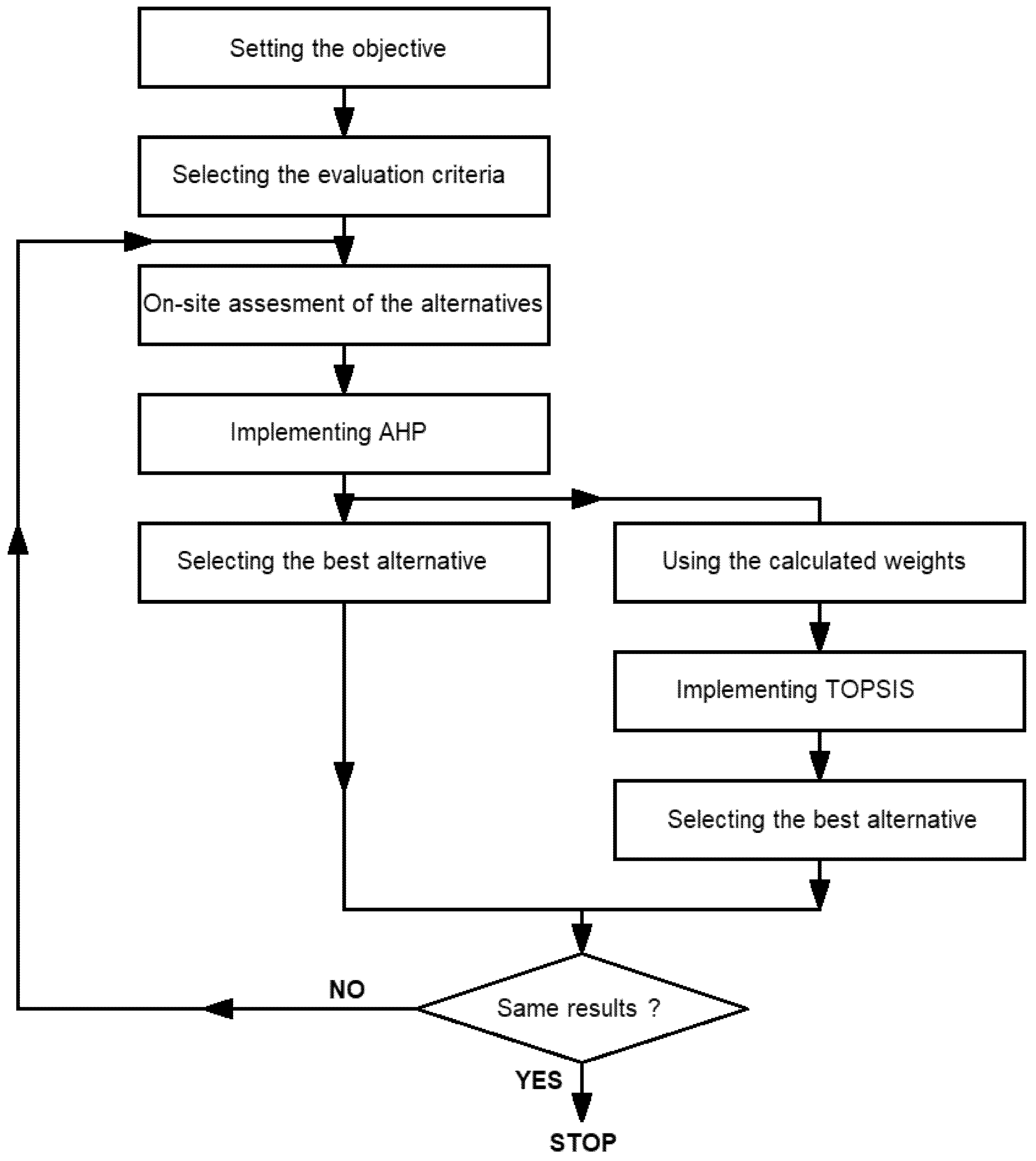
The proposed approach aims to identify which alternative is the safest by analyzing the existing situation of three machining workshops. Of course, the method is intended to have a reasonable degree of generality to be useful for safety comparisons of any machining workshops that meet certain conditions, which will be presented in the following paragraphs. The approach relies upon a joint implementation of AHP and TOPSIS as MCDM techniques.
The weights calculated during the implementation of AHP will be further used during TOPSIS implementation.
Finally, if both methods indicate the same alternative as being the best option, the analysis will be considered finished, and the results will be considered as having a reasonable degree of trustworthiness. If the results of running both AHP and TOPSIS indicate a difference, the analysis must be resumed, and the input data must be analyzed again, possibly requesting the assistance of new specialists.
Figure 1 presents a flowchart of the approach developed in this paper.
The safety of a manufacturing workshop using mostly CNC machine tools as technological equipment depends on the way these machines are running. One must keep in mind several aspects regarding the CNC machine tools:
- These are very complex pieces of equipment, requiring highly trained workers to operate them. Many literature references indicate potential contact with moving parts of the machine tools as the main sources of accidents in the manufacturing industry [27,28,29]. This is particularly important when the movements are fully automated (for CNC machine tools) [30,31]. The moving parts of CNC machine tools can inflict accidents not only during the machining stage but also during the setup, maintenance and cleaning stages [27]. The activities are also very complex and should be performed only by highly trained machining operators [10];
- The machines are working in a fully automatic way, controlled by a numerical code (program). After the program is started, the machining process (consisting of technological movements of the machine slides and performed in high velocities and involving high forces and torques) runs automatically. Any errors within the program will lead to errors within the machining process and result in potential collisions (due to erroneous technological movements) [32];
- Many software tools (computer-aided design (CAD)/computer-aided manufacturing (CAM) software packages) were developed to assist the programming process (the process of generating the numerical code that controls the machine), but the efficiency of these tools depends heavily on their purchase price. While many authors are highlighting the fact that, due to higher complexities of the surfaces that have to be machined, usually requiring five-axis tool paths (collisions are also a major source of safety risks [32,33,34]), it is also recognized that many CAM software packages do not provide collisions detection facilities. Moreover, not all machining workshops are using such software tools, mostly due to financial reasons;
- Machine tool vendors are aware of the possible consequences of erroneous technological movements occurring in CNC machine tools (which can not only damage these expensive pieces of equipment but, most importantly, can also affect the safety of the operators) and are focused on developing solutions to avoid these situations. Thus, every new generation of CNC machine tools is fitted with various safety systems, but most of them are optional, so they are not present on every latest machine (and not present at all on older ones);
- Presently, in the context of a highly competitive market, manufacturers try to reduce the overall manufacturing time (OMT) of every machined part. OMT for a given part has many components, including [35] setup time, processing/machining time, moving time and waiting time. Reducing the OMT is achieved not only by optimizing the machining process but also by overloading the machine tools and reducing the setup time. Overloading and reducing the setup time (which is paramount for such complex technological equipment) can generate various issues that are considered potential sources of safety problems. On the other hand, a comprehensive study presented in [35] has indicated “dedicated equipment” as an efficient method for reducing all components of the OMT. Thus, it can be presumed that the greater the number of machine tools available for a given manufacturing task, the easier it will be to reduce the working time without increasing safety risks.
To assess the relative safety of a machining workshop, a set of four criteria was proposed. Each criterion is detailed below.
C1—Training of the operators (TRO): This criterion takes into consideration the certified training of the CNC machine tool operators. In an emerging market (as the one considered) with a dramatic workforce crisis due to migration, it is quite hard to find qualified operators. Hands-on training at the workshop level could be a solution, but it must be conducted by certified trainers, the results of the training must be certified and proper diplomas must be issued. Consequently, this criterion does not assess how skilled the operators are, but how qualified and trained they are for the specific task. Thus, it evaluates the qualification of the operators by means of proper certification papers.
C2—Quality of programming (QPR): This criterion takes into consideration whether the programming department has access to computer-aided tools for programming, such as CAD/CAM software package tools. It also assesses whether the software package (if present) belongs to the high-end, middle-range or entry-level category. The classification of the software package in one of these categories will be made based on the purchase price.
C3—Machine endowment for safety (MES): This criterion will assess whether the CNC machine tools within the workshop are fitted with modern safety systems, such as realistic simulation with collision control embedded on the machine CNC controller and other advanced safety systems (e.g., tool breakage monitoring systems, motors overload monitoring systems). Most modern CNC machine tool manufacturers provide these systems as optional when purchasing a new machine, and many customers do not acquire them because of their high prices. Thus, if these systems are not standard, their presence is regarded as an assessment criterion for safety.
C4—Production load on a machine (PLD): This criterion will compare the overall number of machine tools able to perform a given machining task for each analyzed workshop. According to the criterion, it is considered that a smaller number of machine tools available for a manufacturing task (so a higher load on the machine) can adversely affect safety. This criterion could be affected by large differences in size between considered workshops (for example, if one workshop owns 100 machines and the other one only 10 machines). Thus, the proposed method is intended to be applied only to machining workshops belonging to small and medium-sized enterprises (SMEs) with a total number of employees less than 250. This staff number limitation (250 being the maximum number of employees allowed by law in many countries for the company to be considered an SME) is considered to ensure the fact that the total number of machine tools is relatively close from one SME to another.
In order to implement the proposed method, three machining workshops (WKS 01, WKS 02 and WKS 03) were evaluated. The preliminary requirements imposed to the evaluated units, for the method to be applied were the following:
- The workshop has to belong to an SME with an overall number of employees less than 250, being its only machining unit. The method can hardly quantify the complex effects and connections that appear in a large company that has several machining workshops;
- The evaluated workshops must be close in terms of size (with regard to the overall number of employees involved in manufacturing activities and the overall number of CNC machine tools), ensured by the imposed limitation that the analyzed workshops belong to SME-type companies. Similar sizes are not required, with most of the entries used for evaluation expressed as percentages, however, at least the same order of magnitude for the above-mentioned numbers is expected;
- Finally, the acquisition of data required for analysis has to be performed by specialists, with many entries to be assessed requiring a high degree of manufacturing expertise in order to be categorized, along with full cooperation from the staff of the assessed workshops. Thus, questionnaires are not recommended for this purpose; on-site observation and data gathering and processing are recommended instead.
3. Results and Discussion
3.1. AHP Method
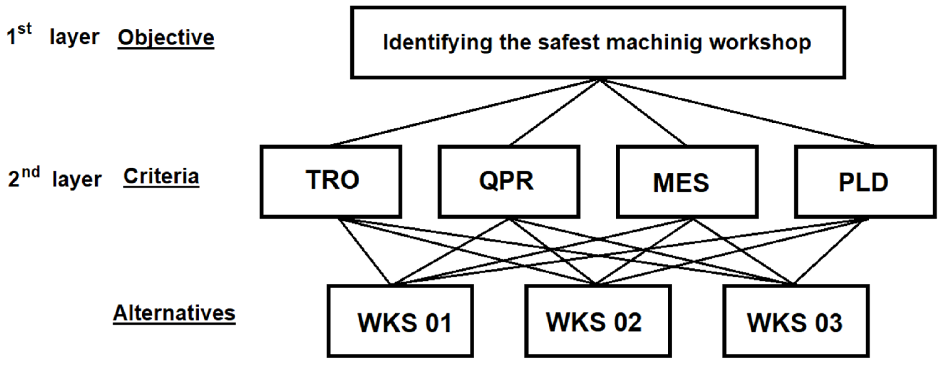
To implement the AHP method, the first step involves setting an objective. For the proposed approach, the objective was to identify the safest machining workshop out of three alternatives. After setting the objective, a set of four criteria introduced above were used for assessing the alternatives.
The layered structure of AHP implementation is synthesized in Figure 2.
In the first stage of the proposed approach, according to the AHP method, the above-proposed criteria were compared against each other by the authors [14,15], using pairwise comparisons of i and j elements in order to determine the aij value.
For the comparison, the scale introduced in [14] was used:
- 1—equally important;
- 3—weakly more important;
- 5—strongly more important;
- 7—demonstrably more important;
- 9—absolutely more important.
The intermediary values (2, 4, 6 and 8) are treated as compromise judgments.
After running the pairwise comparisons of the C1–C4 criteria, the preference matrix A was generated and stored in Table 1.
As an exemplification, the first line of Table 1 can be explained in the following manner:
- Quality of programming (C2) is judged as weakly more important as the training of the operators (C1);
- Machine endowment for safety (C3) is judged as strongly more important as the training of the operators (C1);
- Training of the operators (C1) is judged as a compromise judgment between equally important and weakly more important as the production load on a machine (C4).
The following stage of AHP, as stated in [14,15], necessitates the normalization of the matrix A followed by the generation of matrix B by using the formula:
Table 2 was used to store the calculated normalized B matrix.
The eigenvectors w (the arithmetic average method was used for their calculation) for each row of the matrix B (normalized) were introduced on the last column.
The next step of the AHP process, according to [14,15] involves the consistency check of the proposed comparisons, by calculating the maximal eigenvalue using the following formula:
Table 3 stores the random consistency index, defined in [15], permitting the calculation of the consistency ratio CR (for a 4-dimensional matrix, 0.90 was used as r-value).
The following formula was used for CR:
Consequently, the comparisons made during the building of A and B matrixes are consistent, a fact verified by the CR value, which is smaller than 10% (9.1901%) [14,15].
Table 4 presents the quantitative values obtained after analyzing the on-site situation of the three considered machining workshops: WKS 01, WKS 02 and WKS 03.
A detailed description of the meaning of each entry from Table 4 is presented below.
Qualified CNC machine tool operators (QMO): This entry considers the total number of machine operators in the three assessed workshops holding valid documents (diplomas and/or certificates) to confirm that they are trained as CNC machine tool operators. Because the overall number of machine operators is different for each workshop, the entry was expressed as a proportion (number divided by 100-percentage) of the overall operators working in each workshop.
Engineers in the programming department (EPD): This entry considers the total amount of engineers (mechanical and/or manufacturing engineers—seen as graduates of at least a bachelor’s degree in engineering) who work in the programming department of each assessed workshop. Modern CAM software packages have significantly eased the task of generating CNC programs, so many company managers believe that CNC programming tasks can be performed by technicians or even operators. The idea that only software skills to master CAM software are sufficient for CNC programming is erroneous in many ways. Extensive knowledge of machining technology, tools and cutting regimes and technological equipment (CNC machine tools), which are mastered only by mechanical and/or manufacturing engineers, are also required to produce optimized CNC programs (in terms of both manufacturing and safety issues). Indeed, simple and repetitive CNC programs can be generated by technicians or operators, but at least a final check of them must be done by an engineer. This entry was also expressed as a proportion (number divided by 100-percentage) of all personnel in the programming department of each workshop.
High-end CAD/CAM software (HEC) available, middle-range CAD/CAM software (MRC) available, and entry-level CAD/CAM software (ELC) available: An explanation with regard to how the CAD/CAM software was assessed as high-end/middle-range/entry-level will follow. The first criterion considered was the price, using the following limit: more than 10,000 (HEC), between 5000 and 10,000 (MRC), and under 5000 (ELC), where all prices are considered in euros. The second criterion of considering a software package as HEC/MRC/ELC was the results of the periodical surveys presented on www.cnccookbook.com (accessed on 22 December 2020). Here, it is notable that both CAD and CAM software packages were considered, and the prices were calculated for the full package (CAD+CAM). Moreover, classifying a CAD/CAM software package as HEC/MRC/ELC does not assess its overall quality, but rather how complete the package is (how many modules and features are included within the package). Below, a short feature comparison is presented to clarify the concepts (it is notable here that the comparison is intended to be neither exhaustive nor complete):
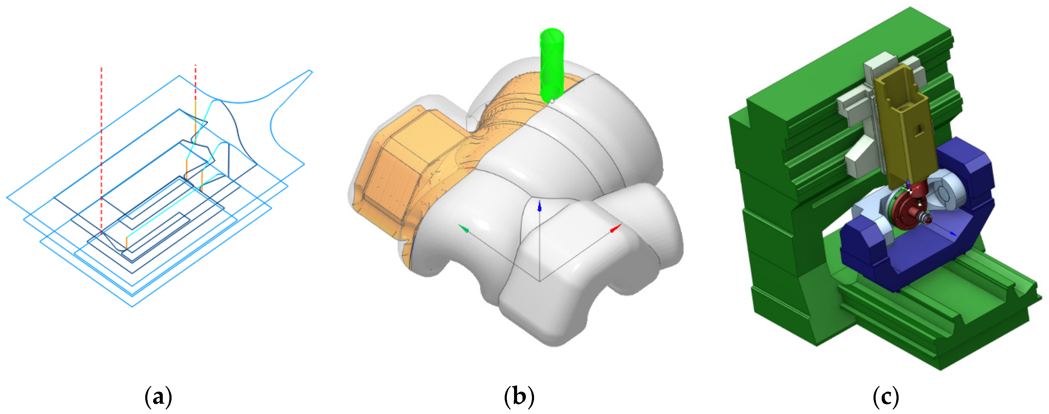
- An ELC software package generates the CNC program and simulates only the trajectories of the programmed points of the tools (the relative movements between tools and workpiece are not simulated, the material-removing process is not simulated, and the displacements of the machine moving elements (slides and tables) are not simulated; thus, collisions between tools and workpiece and between machine moving elements cannot be visualized). Usually, this type of straightforward simulation is called backplot simulation (Figure 3a);
- An MRC software package generates the CNC program and simulates the relative movements between tools and workpiece and the material removing process; therefore, collisions between tools and workpiece can be identified (the movements of the machine moving elements (slides and tables) are not simulated. Thus, collisions between machine moving elements cannot be visualized). Usually, this type of simulation is called solid simulation (Figure 3b);
- An HEC software package generates the CNC program and simulates the relative movements between tools and workpiece, the material removing process and the displacements of the machine moving elements (by using a 3D model of the CNC equipment). Thus, collisions between tools and workpieces and between machine-moving elements can be easily visualized. Usually, this type of simulation is called solid simulation (Figure 3c).
CNC controllers with embedded simulation with collision control (CES): Some modern CNC controllers (Heidenhain 530i, Fanuc 31i, Okuma OSP-P300M, Sinumerik 840 D—the list is neither exhaustive nor complete) are fitted with advanced simulation capabilities. Thus, the CNC controller is able to simulate the CNC program (NC code) and to visualize all types of collisions mentioned above. However, this feature is in most cases an optional one and usually very expensive; therefore, most CNC machine tool users do not acquire it when buying a machine. Usually, programmers prefer to rely on simulations issued by CAD/CAM software packages in order to avoid collisions. However, as presented before, only HEC software packages can realistically simulate all potential movements occurring on the CNC machine tool and consequently can identify and prevent/remove all potential collisions. Moreover, HEC software packages simulations are based on a kinematic model of the machine tool, which can or cannot be entirely accurate, while simulations performed by CES are based on the real physical machine tool, which is much more realistic and accurate. Consequently, the presence of CES significantly increases the overall safety of the machining processes occurring on the CNC machine tool. Because the overall number of CNC machine tools fitted with this feature is different for each workshop, the entry was expressed as a percentage from the total number of machines existing in each facility.
CNC machine tools with advanced safety systems (MAS): Modern CNC machine tools can optionally be equipped with advanced safety systems which are able to prevent and avoid various hazards. For example, there are systems that monitor the tools within the main spindle (either by measuring the power consumption or by measuring the acoustic emission) and can take preventive actions (stopping the main spindle) when a tool breakage is expected to occur. Another example is systems based upon current sensors, which are monitoring the loads (resistant torques) at each feed motor (and for the main spindle motor). These systems can prevent overloads, which can damage either the feed drive systems or the main spindle drive systems. Being optional and usually very expensive, these systems are also not acquired (usually) when a CNC machine tool is bought. Indeed, avoiding tool breakages and driving system overloads also increases the overall safety of the CNC machine tool. This entry was also expressed as a percentage (according to the overall number of the CNC machine tool existing in each workshop).
Number of CNC machine tools (NMT): This entry is a purely quantitative one and is used to assess how the production load may spread between the technological equipment within the assessed workshops. As stated above, the proposed method is designed to evaluate workshops that are quite similar by size and endowment; therefore, this entry is assessed in an absolute manner (not as a percentage).
Entry 1 (Qualified CNC machine tool operators (QCO)) from Table 4 was used as a quantitative assessment for the C1 criterion, entries 2–5 (EPD, HEC, MRC and ELC) for the C2 criterion, entries 6–7 (CES and MAS) for the C3 criterion and entry 8 (NMT) for the C4 criterion. A graphical synthesis of how every entry from Table 4 was used for the quantitative assessment of C1–C4 criteria is presented in Figure 4.
The next stage requires the assessment of the three machining workshops by means of the C1–C4 criteria. The results of the evaluations are presented in Table 5, Table 6, Table 7 and Table 8.
The eigenvectors calculated as arithmetic averages are stored on the last column of Table 5, Table 6, Table 7 and Table 8.
At this stage, matrix C can be generated, which contains in its columns the above-mentioned eigenvectors. It is notable here that the order of the columns of C was established according to the eigenvectors from Table 2, in descending order, as C2, C3, C1 and C4.
After the multiplication between C and w matrixes, the preference vector x was determined:
Finally, by analyzing Equation (5), one can notice the preference vector has its largest value on the third row, which certifies that the best options, from a safety point of view, are represented by the third workshop (WKS 03).
3.2. TOPSIS Method
The initial stage of the TOPSIS method requires the building of the decision matrix, which is presented in Table 9. A set of weights is needed for each criterion, which was calculated using the AHP method.
The following stage requires the calculation of the normalized decision matrix, according to the formula
where xij—elements of the decision matrix, i—number of lines from 1 to m, j—number of columns from 1 to n (for our particular case m = 3, n = 4) and rij—elements of the normalized decision matrix.
By using the weights determined by means of the AHP method, the elements of the weighted decision matrix vij can be determined using the formula
where wi—the weights from the first line of Table 9.
The next step involves the detection of the “positive ideal solution (PIS)” and “negative ideal solution (NIS)”, according to the Equation
where J—is linked with benefit (advantageous) criteria and J′—is linked with cost (disadvantageous) criteria.
The next stage involves the computation of the separation distance of each competitive alternative from the ideal and non-ideal solution using the following formulae:
After that, the “relative closeness to the ideal solution” has to be calculated, according to
Finally, the alternatives can be ranked, the best being the one with the greatest value of the “relative closeness to the ideal solution”.
The calculations presented in the Equation from (6) to (12) can be conducted automatically using the free utility from https://decision-radar.com/ (accessed on 15 December 2020).
Thus, the weighted decision matrix is the following:
The positive ideal solution is depicted below
while the negative ideal solution is the following:
The separation distance from the ideal solution is
while the separation distance from the non-ideal solution is
Finally, the relative closeness to the ideal solution for the three alternatives are presented below:
According to Equation (18), the highest relative closeness to the ideal solution can be noticed for WKS 03; therefore, this workshop is the best option from a safety point of view.
4. Conclusions
This work proposed a method for selecting the safest machining workshop out of three existing alternatives. To determine the trustworthiness of the results, a combined approach relying upon both AHP and TOPSIS methods was used. After running the analysis, both MCDM methods have indicated the same workshop (WKS 03) as the best option.
The method made use of the advantages of both AHP (ability to deal with both quantitative and qualitative inputs) and TOPSIS (considered very easy to apply, among other advantages).
A set of criteria was proposed as the basis of the implementation, which was considered by the authors as able to quantify significant safety-related issues. The main objective of the proposed approach was the safety-related issues linked with the use of computer numerically controlled (CNC) machine tools, seen as the main technological equipment in modern machining workshops.
The advantages of the proposed method are its quite straightforward implementation and the ease of data gathering (if highly trained manufacturing specialists are used for this purpose). The proposed criteria are easy to evaluate, both in a quantitative and qualitative way.
The proposed work also has several limitations. First, the selection of the considered criteria was made by the authors according to their opinions and expertise and is consequently affected by subjectivity. It can be considered that the problems targeted and quantified by the selected criteria are indeed related to the relative safety of a machining workshop, but different specialists could select different criteria for the same inputs (problems).
Special mention must be made with regard to the C1 criterion, which assesses the training of the operators. At present, it is based entirely on formal recognition of the qualifications, while a better approach should take into consideration their real skills and competencies. Formal qualifications are possibly not the most efficient way to assess their actual skills and competencies, because, for example, a certificate could be obtained some time ago and the skills are not practiced for some time. Thus, the training of the operators should be much better assessed by practical and theoretical tests. However, it was quite difficult to organize such tests, due both to time issues (a lot of time in which the operators could not perform their actual machining tasks) and willingness (it was a research program, accepted by the companies as such, but with limited involvement from personnel). Another drawback is that it is quite difficult to assess the method’s efficiency because that would request a long period of experimental data gathering and analysis.
Further research will be oriented on finding ways to demonstrate the efficiency of the method by running a comprehensive experimental program. Additionally, future research will tackle more advanced methods of TOPSIS and AHP, as reported by the literature [36,37,38], trying to integrate them into the proposed approach.
Author Contributions
Conceptualization: L.-I.C. and R.-E.B.; methodology: R.-E.B., L.-I.C. and S.-G.R.; investigation: S.-G.R. and R.-E.B.; resources: L.-I.C. and S.-G.R.; writing—original draft preparation: R.-E.B.; writing—review and editing: R.-E.B.; project administration: L.-I.C. All authors have read and agreed to the published version of the manuscript.
Funding
This research was funded by the Romanian Ministry of Research and Innovation CCCDI-UEFISCDI, by means of the project PN-III-P1-1.2-PCCDI-2017-0446/nr. 82PCCDI/2018, within PNCDI III, project title: “Smart manufacturing technologies for advanced production of parts” and by means of the project “SafeEngine-Blended Learning through Innovative Tools for Sustainable and Safety Engineering and Social Inclusion”, Grant Number 2020-1-RO01-KA203-080085.
Institutional Review Board Statement
Not applicable.
Informed Consent Statement
Not applicable.
Conflicts of Interest
The authors declare no conflict of interest.
References
- Djatmiko, R.D.; Adhitama, R.K.; Prasetya, T.A. The analysis of machining job risk in vocational workshop. In Journal of Physics: Conference Series, Proceedings of the International Conference on Vocational Education of Mechanical and Automotive Technology, Yogyakarta, Indonesia, 12 October 2019; IOP Publishing: Bristol, UK, 2019; Volume 1446. [Google Scholar]
- Laflamme, L.; Backström, T.; Döös, M. Typical accidents encountered by assembly workers: Six scenarios for safety planning identified using multivariate methods. Accid. Anal. Prev. 1993, 25, 399–410. [Google Scholar] [CrossRef]
- Samant, Y.; Parker, D.; Brosseau, L.; Pan, W.; Xi, M.; Haugan, D. Profile of Machine Safety in Small Metal Fabrication Businesses. Am. J. Ind. Med. 2006, 49, 352–359. [Google Scholar] [CrossRef]
- Munshi, K.; Parker, D.; Samant, Y.; Brosseau, L.; Pan, W.; Xi, M. Machine Safety Evaluation in Small Metal Working Facilities: An Evaluation of Inter-Rater Reliability in the Quantification of Machine-Related Hazards. Am. J. Ind. Med. 2005, 48, 381–388. [Google Scholar] [CrossRef] [PubMed]
- Villani, V.; Pini, F.; Leali, F.; Secchia, C. Survey on human–robot collaboration in industrial settings: Safety, intuitive interfaces and applications. Mechatronics 2018, 55, 248–266. [Google Scholar] [CrossRef]
- Duro, J.A.; Padget, J.A.; Bowen, C.R.; Kim, H.A.; Nassehi, A. Multi-sensor data fusion framework for CNC machining monitoring. Mech. Syst. Signal Process. 2016, 66, 505–520. [Google Scholar] [CrossRef] [Green Version]
- Lauro, C.H.; Brandão, L.C.; Baldo, D.; Reis, R.A.; Davim, J.P. Monitoring and processing signal applied in machining processes—A review. Measurement 2014, 58, 73–86. [Google Scholar] [CrossRef]
- Pereira, A.C.; Romero, F. A review of the meanings and the implications of the Industry 4.0 concept. Procedia Manuf. 2017, 13, 1206–1214. [Google Scholar] [CrossRef]
- Mourtzis, D.; Zogopoulos, V.; Katagis, I.; Lagios, P. Augmented Reality based Visualization of CAM Instructions towards Industry 4.0 paradigm: A CNC Bending Machine case study. Procedia CIRP 2018, 70, 368–373. [Google Scholar] [CrossRef]
- Pagell, M.; Barber, A.E. The strategic choice of operator skills in CNC installations. New Technol. Work Employ. 2000, 15, 65–86. [Google Scholar] [CrossRef]
- Berner, B. Learning Control: Sense-Making, CNC Machines, and Changes in Vocational Training for Industrial Work. Vocat. Learn. 2009, 2, 177–194. [Google Scholar] [CrossRef]
- Majid Behzadian, M.; Otaghsara, S.K.; Yazdani, M.; Ignatius, J. A state-of the-art survey of TOPSIS applications. Expert Syst. Appl. 2012, 39, 13051–13069. [Google Scholar] [CrossRef]
- Shih, H.-S.; Shyur, H.-J.; Lee, E.S. An extension of TOPSIS for group decision making. Math. Comput. Model. 2007, 45, 801–813. [Google Scholar] [CrossRef]
- Saaty, T.L. The Analytic Hierarchy Process: Planning, Priority Setting, Resource Allocation; McGraw-Hill: New York, NY, USA, 1980; p. 287. [Google Scholar]
- Saaty, T.L. Decision Making for Leaders: The Analytic Hierarchy Process for Decisions in a Complex Word; RWS Publication: Pittsburgh, PA, USA, 1990. [Google Scholar]
- Saaty, T.L. Decision making with the analytic hierarchy process. Int. J. Serv. Sci. 2008, 1, 83–98. [Google Scholar] [CrossRef] [Green Version]
- Ishizaka, A.; Labib, A. Review of the main developments in the analytic hierarchy process. Expert Syst. Appl. 2011, 38, 14336–14345. [Google Scholar] [CrossRef] [Green Version]
- Russo, R.D.F.S.M.; Camanho, R. Criteria in AHP: A Systematic Review of Literature. Procedia Comput. Sci. 2015, 55, 1123–1132. [Google Scholar] [CrossRef] [Green Version]
- Sahin, B.; Yip, T.L. Shipping technology selection for dynamic capability based on improved Gaussian fuzzy AHP model. Ocean. Eng. 2017, 136, 233–242. [Google Scholar] [CrossRef]
- Sahin, B.; Senol, Y.E. A Novel Process Model for Marine Accident Analysis by using Generic Fuzzy-AHP Algorithm. J. Navig. 2015, 68, 162–183. [Google Scholar] [CrossRef]
- Sahin, B.; Kum, S. Risk Assessment of Arctic Navigation by Using Improved Fuzzy-AHP Approach. Int. J. Marit. Eng. 2015, 157, 241–250. [Google Scholar] [CrossRef]
- Zyoud, S.H.; Fuchs-Hanusch, D. A bibliometric-based survey on AHP and TOPSIS techniques. Expert Syst. Appl. 2017, 78, 158–181. [Google Scholar] [CrossRef]
- Onder, E.; Dag, S. Combining analytical hierarchy process and TOPSIS approaches for supplier selection in a cable company. J. Bus. Econ. Financ. 2013, 2, 56–74. [Google Scholar]
- Racz, S.-G.; Breaz, R.-E.; Cioca, L.-I. Evaluating Safety Systems for Machine Tools with Computer Numerical Control using Analytic Hierarchy Process. Safety 2019, 5, 14. [Google Scholar] [CrossRef] [Green Version]
- Racz, S.-G.; Breaz, R.-E.; Cioca, L.-I. Hazards That Can Affect CNC Machine Tools during Operation—An AHP Approach. Safety 2020, 6, 10. [Google Scholar] [CrossRef] [Green Version]
- Bologa, O.; Breaz, R.E.; Racz, S.G.; Crenganiș, M. Decision-making tool for moving from 3-axes to 5-axes CNC machine-tool. Procedia Comput. Sci. 2016, 91, 184–192. [Google Scholar] [CrossRef] [Green Version]
- Aneziris, O.N.; Papazoglou, I.A.; Konstandinidou, M.; Baksteen, H.; Mud, M.; Damen, M.; Bellamy, L.J.; Oh, J. Quantification of occupational risk owing to contact with moving parts of machines. Saf. Sci. 2013, 51, 382–396. [Google Scholar] [CrossRef]
- Chinniah, Y. Analysis and prevention of serious and fatal accidents related to moving parts of machinery. Saf. Sci. 2015, 75, 163–173. [Google Scholar] [CrossRef]
- Chinniah, Y.; Aucourt, B.; Bourbonnière, R. Safety of industrial machinery in reduced risk conditions. Saf. Sci. 2017, 93, 152–161. [Google Scholar] [CrossRef]
- Hietikko, M.; Malm, T.; Alanen, J. Risk estimation studies in the context of a machine control function. Reliab. Eng. Syst. Saf. 2011, 96, 767–774. [Google Scholar] [CrossRef]
- Backström, T.; Döös, M. Problems with machine safeguards in automated installations. Int. J. Ind. Ergon. 2000, 25, 573–585. [Google Scholar] [CrossRef]
- Tran, D.T. Algorithms for collision detection and avoidance for five-axis NC machining: A state of the art review. Comput. Aided Des. 2014, 51, 1–17. [Google Scholar] [CrossRef]
- Chen, T.; Ye, P.; Wang, J. Local interference detection and avoidance in five axis NC machining of sculptured surfaces. Int. J. Adv. Manuf. Technol. 2005, 25, 343–3499. [Google Scholar] [CrossRef]
- Zhiwei, L.; Hongyao, S.; Wenfeng, G.; Jianzhong, F. Approximate tool posture collision-free area generation for five-axis CNC finishing process using admissible area interpolation. Int. J. Adv. Manuf. Technol. 2012, 62, 1191–1203. [Google Scholar] [CrossRef]
- Johnson, D.J. A Framework for Reducing Manufacturing Throughput Time. J. Manuf. Syst. 2003, 22, 283–298. [Google Scholar] [CrossRef]
- Sahin, B.; Yip, T.L.; Tseng, P.-H.; Kabak, M.; Soylu, A. An Application of a Fuzzy TOPSIS Multi-Criteria Decision Analysis Algorithm for Dry Bulk Carrier Selection. Information 2020, 11, 251. [Google Scholar] [CrossRef]
- Sahin, B. Route Prioritization by Using Fuzzy Analytic Hierarchy Process Extended Dijkstra Algorithm. J. ETA Marit. Sci. 2019, 7, 3–15. [Google Scholar] [CrossRef]
- Sahin, B.; Yazir, D. An analysis for the effects of different approaches used to determine expertise coefficients on improved fuzzy analytical hierarchy process method. J. Fac. Eng. Archit. Gazi Univ. 2019, 34, 89–102. [Google Scholar] [CrossRef]
Figure 1.
Flowchart of the developed method.

Figure 2.
Layered structure of analytic hierarchy process (AHP) implementation.

Figure 3.
Different types of simulation allowed by computer-aided design (CAD)/computer-aided manufacturing (CAM) software packages: (a) backplot simulation, no tool, no workpiece, no material removal process, no machine is simulated (entry-level CAD/CAM software (ELC)); (b) solid simulation, no machine is simulated (middle-range CAD/CAM software (MRC)); (c) complex simulation (High-end CAD/CAM software (HEC)).

Figure 4.
Assessing the C1–C4 criteria using the entries from Table 4; a graphical synthesis.
Figure 4.
Assessing the C1–C4 criteria using the entries from Table 4; a graphical synthesis.


Table 1.
Preference matrix A.
| Criteria | C1 (TRO) | C2 (QPR) | C3 (MES) | C4 (PLD) |
|---|---|---|---|---|
| C1 | 1 | 1/3 | 1/5 | 2 |
| C2 | 3 | 1 | 2 | 3 |
| C3 | 5 | 1/2 | 1 | 5 |
| C4 | 1/2 | 1/3 | 1/5 | 1 |
Table 2.
Normalized matrix B.
| Criteria | C1 | C2 | C3 | C4 | w |
|---|---|---|---|---|---|
| C1 | 0.1053 | 0.1538 | 0.0588 | 0.1818 | 0.1249 |
| C2 | 0.3158 | 0.4616 | 0.5882 | 0.2727 | 0.4096 |
| C3 | 0.5263 | 0.2308 | 0.2941 | 0.4545 | 0.3764 |
| C4 | 0.0526 | 0.1538 | 0.0588 | 0.0909 | 0.0890 |
Table 3.
Values of consistency indices (CIs).
| Size of Matrix (n) | 1 | 2 | 3 | 4 | 5 | 6 | 7 | 8 | 9 | 10 |
|---|---|---|---|---|---|---|---|---|---|---|
| Random average CI (r) | 0 | 0 | 0.58 | 0.90 | 1.12 | 1.24 | 1.32 | 1.41 | 1.45 | 1.51 |
Table 4.
Quantitative results of the on-site analysis of the considered machining workshops.
| On-Site Situation | WKS 01 | WKS 02 | WKS 03 |
|---|---|---|---|
| Qualified CNC machine tool operators (QCO) [%] | 71 | 88 | 81 |
| Engineers in programming department (EPD) [%] | 100% | 100% | 100% |
| High-end CAD/CAM software available (HEC) | yes | no | no |
| Middle-range CAD/CAM software available (MRC) | no | no | yes |
| Entry-level CAD/CAM software available (ELC) | no | yes | no |
| CNC controllers with embedded simulation with collision control (CES) [%] | 26 | 31 | 35 |
| CNC machine tools with advanced safety systems (MAS) [%] | 21 | 27 | 28 |
| Number of CNC machine tools (NMT) | 26 | 17 | 10 |
Table 5.
Comparison of the machining workshops according to criterion C1.
| C1 | WKS 01 | WKS 02 | WKS 03 | w |
|---|---|---|---|---|
| WKS 01 | 1 | 1/3 | 1/3 | 0.1399 |
| WKS 02 | 3 | 1 | 3 | 0.5736 |
| WKS 03 | 3 | 1/3 | 1 | 0.2864 |
Table 6.
Comparison of the machining workshops according to criterion C2.
| C2 | WKS 01 | WKS 02 | WKS 03 | w |
|---|---|---|---|---|
| WKS 01 | 1 | 5 | 3 | 0.6480 |
| WKS 02 | 1/5 | 1 | 1/2 | 0.1222 |
| WKS 03 | 1/3 | 2 | 1 | 0.2299 |
Table 7.
Comparison of the machining workshops according to criterion C3.
| C3 | WKS 01 | WKS 02 | WKS 03 | w |
|---|---|---|---|---|
| WKS 01 | 1 | 1/3 | 1/5 | 0.1062 |
| WKS 02 | 3 | 1 | 1/3 | 0.2605 |
| WKS 03 | 5 | 3 | 1 | 0.6334 |
Table 8.
Comparison of the machining workshops according to criterion C4.
| C4 | WKS 01 | WKS 02 | WKS 03 | w |
|---|---|---|---|---|
| WKS 01 | 1 | 3 | 5 | 0.6334 |
| WKS 02 | 1/3 | 1 | 3 | 0.2605 |
| WKS 03 | 1/5 | 1/3 | 1 | 0.1062 |
Table 9.
Decision matrix.
| TRO | QPR | MES | PLD | |
|---|---|---|---|---|
| Weights | 0.12 | 0.41 | 0.38 | 0.09 |
| WKS 01 | 7 | 9 | 6 | 10 |
| WKS 02 | 9 | 8 | 8 | 8 |
| WKS 03 | 8 | 7 | 9 | 6 |
Publisher’s Note: MDPI stays neutral with regard to jurisdictional claims in published maps and institutional affiliations. |
© 2021 by the authors. Licensee MDPI, Basel, Switzerland. This article is an open access article distributed under the terms and conditions of the Creative Commons Attribution (CC BY) license (https://creativecommons.org/licenses/by/4.0/).
Share and Cite
MDPI and ACS Style
Cioca, L.-I.; Breaz, R.-E.; Racz, S.-G. Selecting the Safest CNC Machining Workshop Using AHP and TOPSIS Approaches. Safety 2021, 7, 27. https://0-doi-org.brum.beds.ac.uk/10.3390/safety7020027
AMA Style
Cioca L-I, Breaz R-E, Racz S-G. Selecting the Safest CNC Machining Workshop Using AHP and TOPSIS Approaches. Safety. 2021; 7(2):27. https://0-doi-org.brum.beds.ac.uk/10.3390/safety7020027
Chicago/Turabian StyleCioca, Lucian-Ionel, Radu-Eugen Breaz, and Sever-Gabriel Racz. 2021. "Selecting the Safest CNC Machining Workshop Using AHP and TOPSIS Approaches" Safety 7, no. 2: 27. https://0-doi-org.brum.beds.ac.uk/10.3390/safety7020027
Note that from the first issue of 2016, this journal uses article numbers instead of page numbers. See further details here.