Article

Rapid Production of PDMS Microdevices for Electrodriven Separations and Microfluidics by 3D-Printed Scaffold Removal

Department of Analytical Chemistry, Faculty of Science, Palacký University Olomouc, 17. Listopadu 12, 77146 Olomouc, Czech Republic
*
Author to whom correspondence should be addressed.
These authors contributed equally.
On leave from Vienna University of Technology, Resselgasse 38, A-1040 Vienna, Austria.
Submission received: 23 February 2021 / Revised: 27 April 2021 / Accepted: 12 May 2021 / Published: 14 May 2021
(This article belongs to the Special Issue Capillary and Microchip Electrophoresis for Bioanalysis)

Abstract

:
In our work, we produced PDMS-based microfluidic devices by mechanical removal of 3D-printed scaffolds inserted in PDMS. Two setups leading to the fabrication of monolithic PDMS-based microdevices and bonded (or stamped) PDMS-based microdevices were designed. In the monolithic devices, the 3D-printed scaffolds were fully inserted in the PDMS and then carefully removed. The bonded devices were produced by forming imprints of the 3D-printed scaffolds in PDMS, followed by bonding the PDMS parts to glass slides. All these microfluidic devices were then successfully employed in three proof-of-concept applications: capture of magnetic microparticles, formation of droplets, and isotachophoresis separation of model organic dyes.

Graphical Abstract

1. Introduction

Microfluidics represents a continuously growing research field with many applications in chemistry, physics, engineering, biology, and/or biomedical research [1,2,3,4,5,6]. The small amounts of liquid required for experiments as well as the physics of fluids at the microlevel make microfluidics one of the interdisciplinary fields par excellence. The most popular material used for the fabrication of microfluidic devices is polydimethylsiloxane (PDMS), which is cheap and easy to manipulate, produces fine and consistent shapes, is gas permeable, and has a refractive index close to that of glass [7,8,9]. To manufacture these PDMS devices, generally, a master is needed, which is usually obtained by clean-room lithography facilities. PDMS is then poured onto the master. After curing, PDMS is carefully peeled off the master and subsequently chemically bonded to another surface after its activation with oxygen plasma. The major drawback of the setup is the cost of the clean-room facilities, including the investment as well as the contract production of the master. When the user has the master and uses it repeatedly, the costs are greatly reduced. In the case of the need of a new master (new design), one should count greater costs. This can be an issue for early-stage career researchers as well as for people from low-income countries. Hence, there is an interest in the production of so-called low-cost microdevices.
3D printing seems to be an interesting solution. It provides a new approach that offers simplicity in the design of microchips as well as in production, and it allows using materials that may be more compatible with commercial needs. Moreover, significant improvements in 3D printing during the past decade have enabled the production of microfluidic devices within hours for a few dollars. 3D printing is widely adopted in microfluidics using stereolithography (SLA) principles, fused deposition modeling (FDM), and photopolymer inkjet printing. These techniques and their applications have been reviewed many times [10,11,12,13,14].
Most papers deal with the direct 3D printing of materials and the formation of microfluidic devices directly from 3D printers. The printer directly prints PDMS or more commonly different polymeric materials, such as PMMA or fluorinated polymers [15,16,17,18,19,20]. In this approach, the 3D-printed structure forms the surroundings of the channels. The second approach is less traditional. The 3D-printed structures are removed from the final PDMS microdevice. Here, the 3D-printed scaffolds are placed in PDMS and are removed after it has cured. PDMS forms the surroundings, while the 3D-printed structures form the channels. This approach was presented for the first time in two pioneering works in 2015. Hwang et al. [21] mechanically removed the scaffolds by rotating the molds. They also investigated the surface roughness, resolution, and replication of the process used. Saggiomo and Velders [22] created the ESCARGOT methodology where ABS polymer scaffolds were printed, inserted into PDMS, and then removed by dissolving ABS in acetone. This is interesting work because it allows for the printing of three-dimensional microfluidic structures, including spirals that are not easily produced by common silicon wafer-based lithography. In 2018, Dahlberg et al. [23] used a water-soluble polyvinyl alcohol (PVA) filament for the rapid production of PDMS microfluidic devices using the same methodology.
In our work, we studied the production of PDMS microdevices by using 3D-printed scaffold removal. Two setups leading to the fabrication of monolithic PDMS-based microdevices and bonded (or stamped) PDMS-based microdevices were designed. The microdevices were used for three proof-of-concept applications: capture of magnetic microparticles, formation of droplets, and isotachophoresis separation of model organic dyes. We tried to build up a platform for fast and low-cost preparation of microdevices that can be fabricated and also used for a little or non-trained personnel, which seems to be the future of the testing market in the post-COVID era.

2. Materials and Methods

2.1. Chemicals and Materials

All the chemicals, hydrochloric acid, 2-(N-morpholino)ethanesulfonic acid (MES), histidine, 2-hydroxyethylcellulose, bromophenol blue, magnetic microparticles (cat. no. 00239-10ML-F), Fluorinert FC-770, amaranth red, and methanol, were bought from Sigma-Aldrich (St. Louis, MO, USA). Deionized water of 18.2 MΩ.cm was prepared using the Milli-Q system from Millipore (Burlington, MA, USA). The prepolymer of polydimethylsiloxane (PDMS) and the curing agent known as Sylgard 184 were purchased from Elchemco (Prague, Czech Republic). A neodymium magnet (field strength 332 mT) was bought from Neomag, s.r.o. (Třinec, Czech Republic). Syringes (B. Braun type) with the Luer connection were purchased from the local pharmacy.

2.2. 3D Printing

All the structures were created using Autodesk Fusion 360 software (Autodesk, San Rafael, CA, USA). The conversion of the structures to .stl files was done by Autodesk Meshmixer software (San Rafael, CA, USA). The .stl files can be found in the Supporting Material. They were sliced by KISSlicer software v. 1.5 (http://www.kisslicer.com/ accessed on 13 September 2018) and transferred as G-codes to the 3D printer. The TRILAB DeltiX Mini FDM 3D printer using delta kinematics printing (TriLAB Group, Brno, Czech Republic) and a 0.4 mm nozzle was used for printing the structures. Filaments with a diameter of 1.75 mm contained PLA, ABS, ASA, Flexfill 92A (Fillamentum Manufacturing Czech, Hulín, Czech Republic), and BVOH (Verbatim, Tokyo, Japan). The 3D-printed structures were baked for 12 h at 60 °C to prevent inhibitory effects on PDMS.

2.3. Preparation of Monolithic PDMS Microdevices

The 3D-printed structures for monolithic microdevices were precisely placed into a 3D-printed container without touching its walls. PDMS was then poured into the container; it was prepared beforehand by mixing the prepolymer and the curing agent (Sylgard 184) at a ratio of 10:1, stirring properly, and degassing in vacuum for 15 min. The amount of PDMS was adjusted for full immersion of the 3D-printed channels in PDMS (ideally, at least 2 mm of PDMS under as well as over the channel). Then, the container with the 3D-printed structures and PDMS was inserted into the desiccator under vacuum and kept there for at least 48 h at room temperature (~25 °C). Subsequently, the 3D-printed input parts were mechanically removed (broken and removed), and then the 3D-printed channel parts were removed through the free inputs using common tweezers by bending the whole device. Finally, the channels were rinsed with deionized water using a common syringe (the syringe insert fits the input parts of the microdevice).

2.4. Preparation of Bonded PDMS Microdevices

Plane 3D-printed structures were gently glued (using the PDMS prepolymer) on a cleaned Petri dish. Then, PDMS (prepared beforehand by mixing the prepolymer and the curing agent (Sylgard 184) in a ratio of 10:1, stirring properly, and degassing in vacuum for 15 min) was carefully poured into the dish. The dish with the 3D-printed structures and PDMS was inserted into the desiccator under vacuum and kept there for at least 48 h at room temperature (~25 °C). Subsequently, PDMS and the 3D-printed structures were removed from the Petri dish (like the standard procedures for the preparation of PDMS-based microdevices). The 3D-printed parts were removed by inserting the whole device into acetone (for ABS and ASA filaments) or water (for the BVOH filament) for 30 s and then mechanically removed using common tweezers. The PDMS parts with the imprinted channels were rinsed with deionized water and kept dry under the desiccator. Then, they were cut into parts that fit common glass slides. The inserts were cut with a Miltex biopsy punch with a 1.5 mm plunger (Biogen, Prague, Czech Republic). Finally, the PDMS parts were bonded to the glass slides using the hand-held corona treater BD-20AC (Electro-Technic Products, Chicago, IL, USA) [24]. Finally, the channels were rinsed with deionized water.

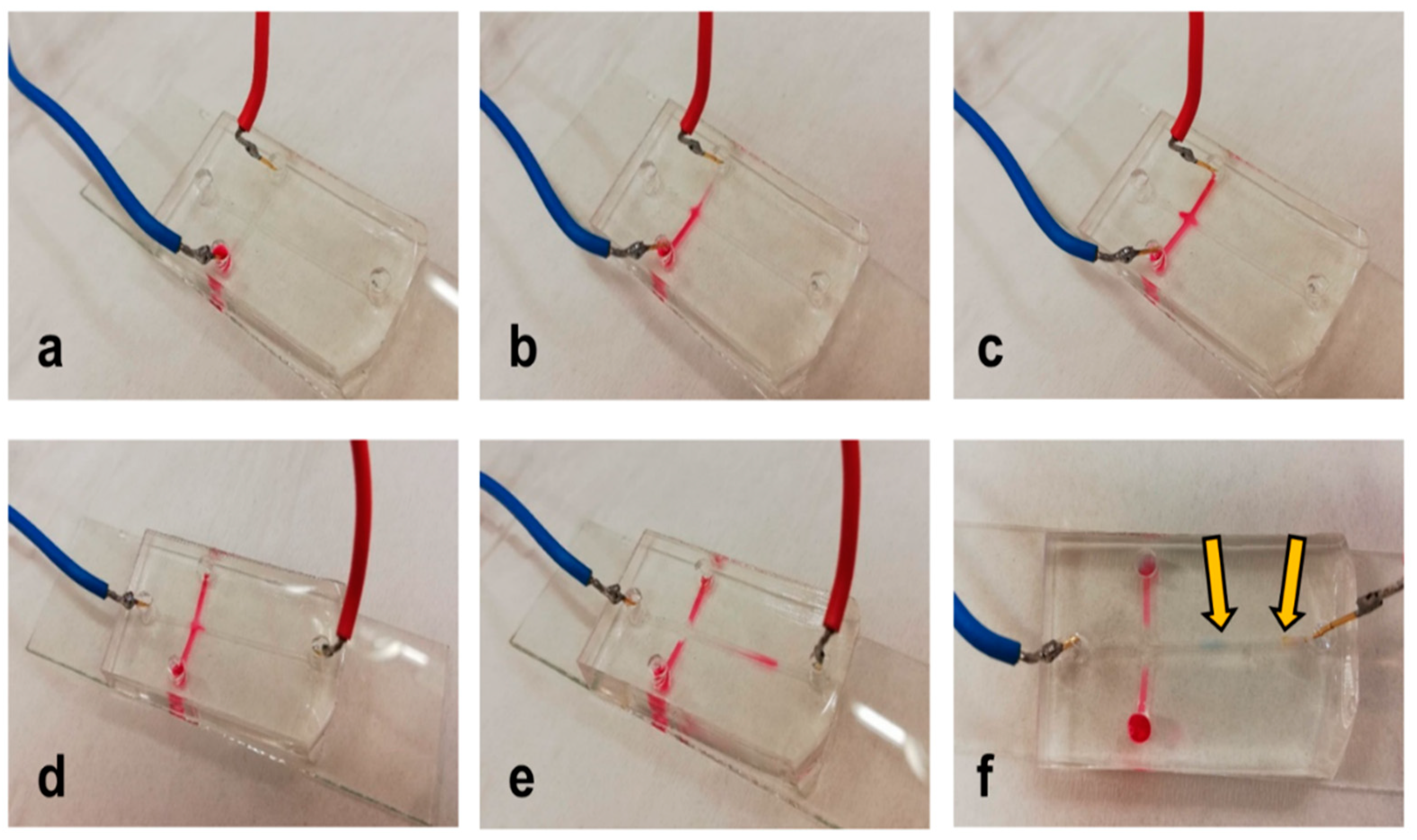
2.5. Isotachophoresis

Isotachophoresis separation of the two model organic dyes—amaranth red and bromophenol blue—was performed as follows (the conditions were adopted from [25,26,27]). First, the channels were rinsed with 1 mg.mL−1 of 2-hydroxyethylcellulose in deionized water. They were then filled with electrolytes. The leading electrolyte was 10 mmol.L−1 of HCl titrated by histidine to pH 6.0, and the terminating electrolyte was 10 mmol.L−1 of MES titrated by histidine to pH 6.0. Both dyes were diluted in the terminating electrolyte. The separation was driven by the application of a 200 V voltage using the Consort EV 243 power supply (Labicom, Olomouc, Czech Republic).

3. Results and Discussion

The first aim of our work was to adopt the ESCARGOT methodology [22] to produce PDMS-based microfluidic devices for electrodriven separation. Linear channels were produced from ABS filaments and poured into PDMS. The microdevices were then put into acetone and sonicated. However, the ABS structures were quite stable; they rested for more than 8 h. Hence, we put the microdevices into only acetone and kept them at room temperature. The ABS structures were fully removed after 2 weeks. This led us to test the use of a BVOH filament, which is dissolvable in hot water (BVOH is also more user-friendly for 3D printing because similar conditions to PLA are used). The BVOH structures were poured into PDMS, and the microdevices were inserted in hot water and sonicated. When using water at ~60 °C, the BVOH structures dissolved after more than 12 h. While using water near the boiling point (~90 °C), the BVOH structures dissolved in approximately 6 h. This is much better than using ABS, but it is still a bit too long.
This led us to the study of the mechanical removal of the 3D-printed structures to produce PDMS-based microdevices. Two production concepts were designed, which led to the fabrication of (i) monolithic PDMS microdevices and (ii) bonded PDMS microdevices (see Figure 1). The monolithic microdevices are produced similarly to the ESCARGOT devices. The 3D-printed channel structures are fully inserted in PDMS. These 3D-printed structures should also contain printed inlets (which should be out of PDMS). The channels are inside the microdevice after the 3D-printed structures’ removal, and they are ready to be used. On the other hand, the bonded (stamped) microdevices are based on the formation of 3D-printed plane channels (i) floating on PDMS or (ii) glued to the base of the Petri dish where PDMS is poured. After the removal of the 3D-printed structures, the PDMS part (with imprints) should be bonded, e.g., to the glass slide, using a standard oxygen plasma procedure.

3.1. Monolithic PDMS Microdevices

The key aspect of the monolithic PDMS microdevices is the mechanical removal. It should not destroy the internal structure made by the 3D printing. Moreover, the channels’ dimension should be as small as possible, but the limitation is also given by the 3D printer (FDM in our case). We studied the use of straight channels formed from one, two, three, and four layers of the printed material (PLA and ASA filaments). The channels were ended with cylinders with a diameter that fit the input of a common syringe. After pouring PDMS, the removal of the 3D-printed structures started with the removal of the cylinders by breaking their connection with the channels by simply bending the whole PDMS device (see Figure S1 in the Supporting Material). Then, the channels were removed by using tweezers, together with bending the device. Concerning the more complicated structures (T-channels or cross-channels), the joint should also be broken.
Then, we studied the effect of the number of 3D-printed layers. One layer meant the formation of a small channel, but the 3D-printing process was not repeatable, and the 3D-printed channels could be easily bent (overall, less than 5% of all the printed channels could be used). The four-layer-based channel was strong and easy to operate with quite a bigger diameter of the final channel. However, it was difficult to break the joints when inserted into PDMS. The mechanical removal also mostly led to the damage of the channels’ structure. The two-/three-layer-based channels were in between. As optimal channels, we chose the three-layer-based channels since they are easier to operate and they can also be easily broken inside PDMS. The channel cross section is shown in Figure S2a in the Supporting Material. The production procedure (3D-printed structure removal) can theoretically damage PDMS. Hence, we studied the reproducibility of the preparation. First, the channels were checked under an optical microscope to avoid any visible destruction. We did not observe any wrong device during our study. Then, we studied the repeatability of migration times of two model dyes using isotachophoresis; see the procedure below. Here, the repeatability (device-per-device, N = 5) was higher than 90%, which represents quite a good result for such a low-cost and fast approach. We also checked the width of the channel in PDMS, measuring 10 points in at least a 3 mm distance (in one microdevice). The relative error was calculated to be about 8%.

3.2. Bonded PDMS Microdevices

As described before, the two methodologies were studied to form bonded PDMS microdevices: (i) floating 3D-printed structures on PDMS before curing and (ii) adhesion of 3D-printed structures to the base of the Petri dish where PDMS was poured (Figure S3 in the Supporting Material). The floating methodology was easier for production because the 3D-printed object was carefully placed on PDMS before it was cured. However, this was only possible for lighter objects that could float on PDMS. In addition, the size of the channels (depth) was given by the weight of the 3D-printed object. After PDMS was cured, the 3D-printed object could be easily removed mechanically or by using the appropriate solvent (acetone for ABS or water for BVOH), which disturbed the contact of the filament and PDMS, and then the 3D-printed object could be mechanically removed easily. The second possibility was more laborious, but the production was more reproducible. The 3D-printed object was glued to the base of the Petri dish where PDMS was poured. We studied the use of common double-sided adhesive tape, common fast-acting (super)glue, and the PDMS prepolymer. The adhesive tape interacted with PDMS, and PDMS’s structure was destroyed. Using superglue and the PDMS prepolymer gave similar results (both could be used), but the PDMS prepolymer was cheaper in our low-series production because it was also used in subsequent steps. The removal of the 3D-printed structures after PDMS’s curing was quite easy because PDMS was removed frequently without the 3D-printed object. Finally, PDMS was cut and bonded to the glass slides using oxygen plasma. The example of the channel cross section is shown in Figure S2b in the Supporting Material. The number of 3D-printed layers had a similar effect, as described in the previous paragraph. Moreover, the fewer number of layers was profitable when using the floating methodology. Contrary to the previous setup, this production procedure is not so sensitive for the PDMS damage. However, we studied the reproducibility of the preparation, too. First, the channels were checked under an optical microscope, and then the repeatability of migration times of two model dyes using isotachophoresis was analyzed. Here, the repeatability (device-per-device, N = 5) was higher than 92%. The width of the channel in PDMS, measuring 10 points in at least a 3 mm distance (in one microdevice), was measured, too, with a relative error of about 5%.

3.3. Proof-of-Concept Applications

Both the monolithic and the bonded PDMS microdevices were tested in the three proof-of-concept applications: capture of magnetic microparticles using a straight-channel microdevice, formation of droplets using a T-channel microdevice, and the isotachophoresis separation of model organic dyes using a cross-channel microdevice. The applications were chosen based on their increasing difficulty as well as the potential applicability of the devices.
First, straight-channel-based microdevices were prepared using both setups. A strong neodymium-based magnet (field strength 332 mT) was put in the middle of the device, and commercial magnetic microparticles dispersed in deionized water were inserted into the channel using a common syringe. The microparticles were captured in the channel. Then, they were then rinsed with deionized water with a blue dye. There was no visible release of the microparticles (Figure 2). Hence, these microdevices can be used for capturing magnetic particles and then for capturing other compounds if the particles are properly modified. Both setups (monolithic and bonded) gave the same results and therefore opened the way for the low-cost production of simple bioassays.
We then prepared T-channel microdevices to study the formation of droplets. Droplet microfluidics is important in many research fields, for example, medicine and biology [28,29,30]. Aqueous droplets are formed in an inert, non-polar, biocompatible solvent. As a proof-of-concept, we used deionized water with red dye as the aqueous phase and Fluorinert FC-770 as the non-polar phase. First, the whole microdevice was rinsed with Fluorinert FC-770. Next, we applied the flow of the aqueous phase from the channel perpendicular to the main straight channel. The flow was regulated by the pressure applied on the syringes. Figure 3 represents the results (a video can also be found in the Supporting Material). Both setups to produce PDMS microdevices are successful. The droplets are quite big compared to the classical microfluidic way. However, they are formed at low cost without using commercial instruments. If pressure regulators or commercial pumps are used, the droplets will be more precise in terms of their size as well as frequency. However, generally, we proved that both the production processes can be used in droplet microfluidics.
Finally, cross-channel microdevices were prepared to test the possibility of the isotachophoresis separation of the two model organic dyes: amaranth red and bromophenol blue. The leading electrolyte was 10 mmol.L−1 of HCl titrated by histidine to pH 6.0, and the terminating electrolyte was 10 mmol.L−1 of MES titrated by histidine to pH 6.0. A mixture of both dyes was diluted by the leading electrolyte. The dyes were electrokinetically loaded into the main channel from the side channels; then, separation occurred in the main channel. The operation is given in detail in Figure S4 in the Supporting Material. As can be seen in Figure 4 (and Figure S5 in the Supporting Material), separation was possible.
This proved that both setups (monolithic and bonded) can be used to produce PDMS-based microdevices for separation. Moreover, the structure of the channel (including its surface inequalities due to both 3D printing of more lines and the removal of 3D-printed parts) did not have a negative effect on the isotachophoresis separation. This is important from the point of view of preparation of microdevices in the comparison with traditional PDMS microdevices. Our setup does not need any highly expensive way of production, and it can be used for a few purposes. There are some other low-cost preparation methods, including laser cutting and scribing adhesive tape [31,32,33]. However, lasers are still more expensive. Scribing and cutting are interesting but should be done carefully to obtain repeatable channels. In our work, we tried to build up a platform for fast and low-cost preparation of microdevices that can be fabricated and also used for little or non-trained personnel. This is of great importance in the testing market. The post-COVID era will increase the needs for small numbers of high-tech labs and lots of self-testing devices. In addition, we believe our approach, including isotachophoresis separation, can be one of the self-testing solutions.

4. Conclusions

In this work, we developed two setups for the low-cost production of PDMS microdevices by using 3D-printed scaffold removal. The first consisted of the production of monolithic PDMS devices using mechanical removal of 3D-printed channels. The second represented the production of a PDMS device with stamped 3D-printed channels (using their chemical as well as mechanical removal), which needed to be bonded to glass slides by oxygen plasma. Both setups were successfully used in three proof-of-concept applications: capture of magnetic microparticles, formation of droplets, and isotachophoresis separation of model organic dyes. Hence, both low-cost production setups can be used in many applications in the field of microfluidics. Monolithic microdevices are, of course, limited in their complexity since they require slow and precise mechanical removal of the 3D-printed parts. Bonded microdevices do not seem to be as limited, and they can be produced with a little bit more precision. Hence, we believe that bonded microdevices are more advantageous for electrodriven separations as well as microfluidics.

Supplementary Materials

The following are available online at https://0-www-mdpi-com.brum.beds.ac.uk/article/10.3390/separations8050067/s1, Figure S1: Removal of 3D-printed structures in monolithic PDMS microdevice; Figure S2: Cross-section of PDMS-based microdevice channels; Figure S3: Stamping 3D-printed scaffolds in PDMS; Figure S4: Procedure of isotachophoresis separation; Figure S5: Example of isotachophoresis on a monolithic PDMS microdevice; Video S1: Production of droplets in a monolithic device; .stl files for 3D printing.

Author Contributions

Conceptualization, L.H. and J.P.; methodology, A.Š., K.K., E.D., S.S., and J.P.; software, J.P.; investigation, A.Š., K.K., E.D., and S.S.; resource, J.P.; writing, J.P.; supervision, J.P.; funding acquisition, J.P. All authors have read and agreed to the published version of the manuscript.

Funding

This research was funded by the Ministry of Education, Youth and Sports of the Czech Republic (Nano4Future CZ.02.1.01/0.0/0.0/16_19/0000754) and by the Palacký University Olomouc (IGA_PrF_2021_021).

Institutional Review Board Statement

Not applicable.

Informed Consent Statement

Not applicable.

Data Availability Statement

All the data are given in this article.

Acknowledgments

The authors thank Vojtěch Tambor and Michal Boháč (TriLAB Group, s.r.o., Brno) for their consultations on 3D printing and Martin Pykal (Department of Physical Chemistry, RCPTM, UP Olomouc) for printing our first 3D structures before we bought our 3D printer.

Conflicts of Interest

The authors declare no conflict of interest.

Abbreviations

PDMSPolydimethylsiloxane
ITPisotachophoresis

References

  1. Fallahi, H.; Zhang, J.; Phan, H.P.; Nguyen, N.T. Flexible microfluidics: Fundamentals, recent developments, and applications. Micromachines 2019, 10, 830. [Google Scholar] [CrossRef] [PubMed] [Green Version]
  2. Liu, D.; Wang, J.; Wu, L.; Huang, Y.; Zhang, Y.; Zhu, M.; Wang, Y.; Zhu, Z.; Yang, C. Trends in miniaturized biosensors for point-of-care testing. Trends Anal. Chem. 2020, 122, 115701. [Google Scholar] [CrossRef]
  3. Ou, X.; Chen, P.; Huang, X.; Li, S.; Liu, B.F. Microfluidic chip electrophoresis for biochemical analysis. J. Sep. Sci. 2020, 43, 258–270. [Google Scholar] [CrossRef] [PubMed]
  4. Mathur, L.; Ballinger, M.; Utharala, R.; Merten, C.A. Microfluidics as an enabling technology for personalized cancer therapy. Small 2020, 16, 1904321. [Google Scholar] [CrossRef]
  5. Scheler, O.; Postek, W.; Garstecki, P. Recent developments of microfluidics as a tool for biotechnology and microbiology. Curr. Opin. Biotechnol. 2019, 55, 60–67. [Google Scholar] [CrossRef]
  6. Nielsen, J.B.; Hanson, R.L.; Almughamsi, H.M.; Pang, C.; Fish, T.R.; Woolley, A.T. Microfluidics: Innovations in materials and their fabrication and functionalization. Anal. Chem. 2020, 92, 150–168. [Google Scholar] [CrossRef]
  7. Raj, K.; Chakraborty, S. PDMS microfluidics: A mini review. J. Appl. Polymer. Sci. 2020, 137, 48958. [Google Scholar] [CrossRef]
  8. McDonald, J.C.; Duffy, D.C.; Anderson, J.R.; Chiu, D.T.; Wu, H.; Schueller, O.J.A.; Whitesides, G.M. Fabrication of microfluidic systems in poly (dimethylsiloxane). Electrophoresis 2000, 21, 27–40. [Google Scholar] [CrossRef]
  9. Duffy, D.C.; McDonald, J.C.; Schueller, O.J.A.; Whitesides, G.M. Rapid prototyping of microfluidic systems in poly (dimethylsiloxane). Anal. Chem. 1998, 70, 4974–4984. [Google Scholar] [CrossRef]
  10. Li, F.; Macdonald, N.P.; Guijt, R.M.; Breadmore, M.C. Increasing the functionalities of 3D printed microchemical devices by single material, multimaterial, and print-pause-print 3D printing. Lab Chip 2019, 19, 35–49. [Google Scholar] [CrossRef] [Green Version]
  11. Au, A.K.; Huynh, W.; Horowitz, L.F.; Folch, A. 3D-printed microfluidics. Angew. Chem. Int. Ed. 2016, 55, 3862–3881. [Google Scholar] [CrossRef] [PubMed]
  12. Waheed, S.; Cabot, J.M.; Macdonald, N.P.; Lewis, T.; Guijt, R.M.; Paull, B.; Breadmore, M.C. 3D printed microfluidic devices: Enablers and barriers. Lab Chip 2016, 16, 1993–2013. [Google Scholar] [CrossRef] [PubMed] [Green Version]
  13. Manzanares Palenzuela, C.L.; Pumera, M. (Bio) Analytical chemistry enabled by 3D printing: Sensors and biosensors. Trends Anal. Chem. 2018, 103, 110–118. [Google Scholar] [CrossRef]
  14. Dixit, C.K.; Kadimisetty, K.; Rusling, J. 3D-printed miniaturized fluidic tools in chemistry and biology. Trends Anal. Chem. 2018, 106, 37–52. [Google Scholar] [CrossRef] [PubMed]
  15. Macdonald, N.P.; Cabot, J.M.; Smejkal, P.; Guijt, R.; Paull, B.; Breadmore, M.C. Comparing microfluidic performance of three-dimensional (3D) printing platforms. Anal. Chem. 2017, 89, 3858–3866. [Google Scholar] [CrossRef]
  16. Li, F.; Macdonald, N.P.; Guijt, R.M.; Breadmore, M.C. Multimaterial 3D printed fluidic device for measuring pharmaceuticals in biological fluids. Anal. Chem. 2019, 91, 1758–1763. [Google Scholar] [CrossRef]
  17. Bhattacharjee, N.; Parra-Cabrera, C.; Kim, Y.T.; Kuo, A.P.; Folch, A. Desktop-sterolitography 3D-printing of a poly (dimethylsiloxane)-based material with Sylgard-184 properties. Adv. Mater. 2018, 30, 1800001. [Google Scholar] [CrossRef]
  18. Romanov, V.; Samuel, R.; Chaharlang, M.; Jafek, A.R.; Frost, A.; Gale, B.K. FDM 3D printing of high-pressure, heat-resistant, transparent microfluidic devices. Anal. Chem. 2018, 90, 10450–10456. [Google Scholar] [CrossRef]
  19. Ji, Q.; Zhang, J.M.; Liu, Y.; Li, X.; Lv, P.; Jin, D.; Duan, H. A modular microfluidic device via multimaterial 3D printing for emulsion generation. Sci. Rep. 2018, 8, 4791. [Google Scholar] [CrossRef]
  20. Comina, G.; Suska, A.; Filippini, D. PDMS lab-on-a-chip fabrication using 3D printed templates. Lab Chip 2014, 14, 424–430. [Google Scholar] [CrossRef]
  21. Hwang, Y.; Paydar, O.H.; Candler, R.N. 3D printed molds for non-planar PDMS microfluidic channels. Sens. Actuator. B 2015, 226, 137–142. [Google Scholar] [CrossRef]
  22. Saggiomo, V.; Velders, A.H. Simple 3D printed scaffold-removal method for the fabrication of intricate microfluidic devices. Adv. Sci. 2015, 2, 1500125. [Google Scholar] [CrossRef] [PubMed]
  23. Dahlberg, T.; Stanger, T.; Zhang, H.; Wiklund, K.; Lundberg, P.; Edman, L.; Andresson, M. 3D printed water-soluble scaffolds for rapid production of PDMS micro-fluidic flow chambers. Sci. Rep. 2018, 8, 3372. [Google Scholar] [CrossRef]
  24. Haubert, K.; Drier, T.; Beebe, D. PDMS bonding by means of a portable, low-cost corona system. Lab Chip 2006, 6, 1548–1549. [Google Scholar] [CrossRef] [PubMed]
  25. Karovicova, J.; Polonsky, J.; Pribela, J.; Simko, P. Isotachophoresis of some synthetic colorants in foods. J. Chromatogr. 1991, 545, 413–419. [Google Scholar] [CrossRef]
  26. Masár, M.; Kaniansky, D.; Madajova, V. Separation of synthetic food colourants by capillary zone electrophoresis in a hydrodynamically closed separation compartment. J. Chromatogr. A 1996, 724, 327–336. [Google Scholar] [CrossRef]
  27. Hárendarčíková, L.; Petr, J. Fabrication of low-cost polydimethylsiloxane master from laminating foil for isotachophoresis separation on a chip. Instrum. Sci. Technol. 2018, 46, 316–325. [Google Scholar] [CrossRef]
  28. Ding, Y.; Howes, P.D.; de Mello, A.J. Recent advances in droplet microfluidics. Anal. Chem. 2020, 92, 132–149. [Google Scholar] [CrossRef]
  29. Dubcombe, T.A.; Dittrich, P.S. Droplet barcoding: Tracking mobile microreactors for high-throughput biology. Curr. Opin. Biotechnol. 2019, 60, 205–212. [Google Scholar] [CrossRef]
  30. Chen, P.; Chen, D.; Li, S.; Ou, X.; Liu, B.F. Microfluidics towards single cell resolution protein analysis. Trends Anal. Chem. 2019, 117, 2–12. [Google Scholar] [CrossRef]
  31. Ren, Y.; Ray, S.; Liu, Y. Reconfigurable acrylic-tape hybrid microfluidics. Sci. Rep. 2019, 9, 4824. [Google Scholar] [CrossRef] [PubMed]
  32. Kalwa, U.; Legner, C.; Wlezien, E.; Tylka, G. New methods of removing debris and high-throughput counting of cyst nematode eggs extracted from field soil. PLoS ONE 2019, 14, e0223386. [Google Scholar] [CrossRef] [PubMed]
  33. Kong, T.; Backes, N.; Kalwa, U.; Legner, C.; Phillips, G.J.; Pandey, S. Adhesive tape microfluidics with an autofocusing module that incorporates CRISPR interference: Applications to long-term bacterial antibiotic studies. ACS Sens. 2019, 4, 2638–2645. [Google Scholar] [CrossRef] [PubMed]
Figure 1. Design of PDMS-based microdevices using 3D-printed scaffold removal: (a) monolithic microdevices; (b) bonded microdevices.
Separations 08 00067 g001
Figure 2. Example of the capture of microparticles; the arrow indicates microparticles.
Separations 08 00067 g002
Figure 3. Example of the production of droplets using a monolithic PDMS-based device: (a) scheme of the setup; (b) formation of droplets.
Separations 08 00067 g003
Figure 4. Example of isotachophoresis on a bonded PDMS microdevice: (a) injection of the sample (t = 0 s), (b) injection of the sample (t = 30 s), (c) injection of the sample (t = 60 s), (d) separation (t = 0 s), (e) migration of the dyes (t = 20 s), and (f) separation. Arrows show the separated dyes; blue cable “+” and red cable “−”.
Separations 08 00067 g004
Publisher’s Note: MDPI stays neutral with regard to jurisdictional claims in published maps and institutional affiliations.

