A Survey on Subsurface Signal Propagation †


Department of Computer and Information Technology, Purdue University, West Lafayette, IN 47906, USA
*
Author to whom correspondence should be addressed.
†
This paper is an extended version of our paper published in our book Signals in the Soil.
‡
Both authors contributed equally to this work.
Smart Cities 2020, 3(4), 1513-1561; https://0-doi-org.brum.beds.ac.uk/10.3390/smartcities3040072
Submission received: 15 October 2020
/
Revised: 18 November 2020
/
Accepted: 19 November 2020
/
Published: 10 December 2020
(This article belongs to the Special Issue Internet of Things in Digital Agriculture)
Abstract
:Wireless Underground Communication (WUC) is an emerging field that is being developed continuously. It provides secure mechanism of deploying nodes underground which shields them from any outside temperament or harsh weather conditions. This paper works towards introducing WUC and give a detail overview of WUC. It discusses system architecture of WUC along with the anatomy of the underground sensor motes deployed in WUC systems. It also compares Over-the-Air and Underground and highlights the major differences between the both type of channels. Since, UG communication is an evolving field, this paper also presents the evolution of the field along with the components and example UG wireless communication systems. Finally, the current research challenges of the system are presented for further improvement of the WUCs.
1. Introduction
Wireless Underground Communication (WUC) is becoming popular because of the security provided by its deployment methodology, i.e., far below the ground. Underground communication was first observed in World War, however, its use was limited to radio propagation techniques only. V. Fritsch and R. Wundt conducted the experiments, in 1938–1940, to study the propagation of radio waves in underground coal mines using small transceivers in the ground. The communication range varied depending upon the nature of the coal, however, an overall range of upto 1000 feet was successfully achieved. In 1942, they conducted another experiment but this time in 100 feet thick salt mine at the depth of 2000 feet. For this experiment, they used horizontal dipole antennas battery operated transmitter and receiver. They were able to successfully communicate over a range of 15 km, i.e., 9–1/2 miles. They performed voice communication using the amplitude modulation. The experiment was performed with extreme care and intelligence avoiding any noise or extra radio signals at transmitter and carefully selecting the location of transmitter and receiver nodes at different locations from each other. It was made sure that no measurable wave existed on the earth surface so that true underground propagation can be studied. Since then, underground communication has come long way with improvement in methodologies and equipment. This paper discusses the potential and challenges of underground communication.
WUC is being used in many applications: border patrol, precision agriculture, and environment monitoring. WUC mainly consist of two components: sensors and communication devices. These components are either completely or partially buried in the soil. WUC aims to provide real-time soil monitoring and sensing. In precision agriculture, WUC is mainly used for sensing and monitoring of soil and other related physical properties [1,2,3,4,5,6,7,8,9,10,11,12,13,14]. The WUC are also being used to implement border monitoring for stop border infiltration [15,16]. Other monitoring applications of WUS includes pipeline monitoring and landslide monitoring [4,14,17,18]. Other important component of WUC is the wireless communication which is proved to be an emerging field of study as well. There exist few models in the literature which represents underground communication. Underwater communication [19,20] has same challenging medium as in underground communication. However, for underwater communication, acoustic waves [19] are used instead of EM waves due to very high attenuation of EM waves in the water. Acoustic propagation has its own disadvantages such as: low quality of physical link and higher delays because of low speed of sound, extremely low bandwidth, challenging deployment and size and cost of equipment. These disadvantages restrict the use of acoustic methods for WUC.
Smart Farming [1,2,3,4,5,6,7,21,22,23,24,25] is an agricultural management process which exploits the spatio-temporal changes in crop, soil, management and production with new technologies to improve the farming experience. Smart farming employs large number of wireless devices to sense crop-related data and send this data to a central control room or server center [26,27]. In recent years, sensing technologies have evolved a lot. These advanced sensing methods are then combined with adaptive input applications (e.g., adaptive application of fertilizers) and soil mapping methods for efficient operation.
The advanced sensing technology have risen the demand for increased data rate and extended communication distance. As per the reports of Cisco’s visual networking index [28], by 2020, 11.6 billion devices are predicted to be connected via Internet. The vastness of this number can be realized by the fact that population of the world, by 2050, is predicted to be 10 billion, i.e., even less than number of devices connected by 2020. To fulfill food requirement of the such huge population of the world, it is imperative to utilize smart farming to its full extent for better and cost-efficient crop production method through timely decision making and conserving natural resources. To that end, it is important to achieve an ubiquitous connectivity on farms by using underground wireless communications channel [21,26,29].
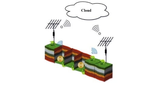
Wireless Underground Communications (WUC) applications can be classified into various categories [30,31,32]. Some of them, for example, includes: environment monitoring such as precision agriculture and landslide monitoring, infrastructure monitoring for better maintenance and operation of underground infrastructure, e.g., preventing leakage, application for determining location can be helpful in locating people stuck in disaster, and security monitoring applications, e.g., to detect infiltration at border through concealed underground devices. Figure 1 shows some of these applications [6,33].
WUC and conventional wireless networks differs majorly with respect to their communication medium. WUC sensor nodes communicate through soil where as over-the-air terrestrial wireless network uses air as a medium to communicate. The signal propagation in soil is never investigated properly before, in fact, electromagnetic (EM) wave propagation was not even considered a viable option for underground communication. Therefore, feasible options and solutions are explored to develop a power-efficient underground communications.
There exists no detailed wireless channel model because of the challenges experienced in developing power-efficient underground communication which also hinders the protocol development in WUC. To overcome this, existing literature was studied in detail along with a very detailed and time-intensive experiments [34,35,36,37,38]. The results from these experiments were analyzed over the period of 18 months to generalize performance of underground communication channel. A summary of those results can be found in [39]. It was found that many soil parameters (e.g., soil texture and moisture and irregular soil surface), and antenna parameters (burial depth, antenna design, and operating frequency) has effect on UG communication. It proved the underground channel dependence on spatio-temporal environmental factors leading to a unique correlation of communication system (information dn communication medium) with environment. Hence, in addition to operational and deployment factors, an underground channel must not ignore these parameters.
A wireless underground communications (WUC) model has been developed and presented in [39]. The model focuses on propagation model rather than antenna problem. The WUC model determines the total signal attenuation and the BER (bit error rate) using three-wave components (direct wave (DW), reflected wave (RW), and lateral wave (LW) factors), dielectric soil properties prediction model, and the signal superposition model. In contrast to existing literature, WUC model captures the gain from the directivity of special antennas instead of simple insulated dipole [6,22]. However, to avoid over-complication of the model, antennas problem are not considered in this model because of large number of antennas schemes.
The in-situ experiments were done without considering lateral wave component. If lateral waves are also considered using special antennas, an extended communication range can be achieved using the same transmitting power. The results obtained from the study helped in designing WUC systems. A strong multi-hop networking solution among the buried nodes can be achieved with long range (distance > 10 m) eliminating the topology dependency on above-ground devices.
In [39], authors have shown that depth has high effect on communication performance. Through empirical evaluations, they observed that even a small change in depth can degrade the communication performance. The difference in communication performance between topsoil and subsoil is because of:
- Soil parameters. Both, topsoil, and subsoil, differs in soil texture and soil moisture [40] which causes the difference in communication for both mediums [1,8,15,34]. For example, topsoil will have more soil moisture level as compared to subsoil during rain or irrigation because it takes longer for water to reach subsoil area [41].
- Soil surface effects. LW and RW component plays an important role in signal strength of topsoil. Therefore, topsoil signal experiences much less attenuation than subsoil.
It is preferred to have a shallow deployment of UG nodes in WUC because it decreases the propagating path in the soil causing signal to suffer less attenuation. However, the depth is highly application-dependent, e.g., for intruder detection, recommended deployment depth is 10 and sport field irrigation, however, for precision agriculture depth of 40–100 cm is mostly recommended.
WUC does not contains only UG nodes. Hybrid WUC is a combination of underground (UG) and above-ground (AG) [1,8,25]. As Hybrid WUC contains multiple types of devices, it also utilize multiple type of links for the communication, i.e., above-ground to underground (AG2UG), underground-to- underground (UG2UG), and underground-to-above-ground (UG2AG). Here, this paper focuses on the characterization fo WUC UG2UG channel. Moreover, other channels, i.e., AG2UG & UG2AG channels, can be characterized using WUC channel model.
Another method of underground communication, not given in Figure 2, is Through-The-Earth (TTE). TTE is applied in areas like military UG communication, geophysical exploration, and mining. It is mainly used to communicate in emergency situations for communicating with people stuck in disasters, e.g., miners stuck in mines [42]. WUC & TTE, with all their similarities, faces completely different set of challenges (see Table 1). For example, a typical depth considered for TTE deployment is very deep (hundreds of meters) as compared to WUC (few centimeters). Therefore, they are considered two different technologies in the literature [25,43,44].
It can be seen in the Table 1 that most of the challenges faced by TTE and WUSN challenges are related to the physical layer. TTE struggles in traversing rocks with long-range communication, and WUSN struggles with long-range communication through soil. Soil moisture highly effect the subsoil communication [15,34,35], therefore, it requires cross-layer approach [15,22]. Moreover, WUC need power-efficient nodes buried for long lasting operations.
Relative permittivity of a soil depends upon the signal frequency and Volumetric Water Content (VWC), therefore, signal frequency indirectly effect the strength of the signal [45,46]. In addition to the frequency, soil conductivity also has an effect on signal attenuation. This is in contrary to the popular belief that signal is less attenuated under smaller frequencies. Hence, signal attenuation cannot be estimated from only soil permittivity as other soil parameters are also involved [45,47].
Soil permittivity estimation has been investigated for specific range of frequencies. All such studies conclude that frequencies around 1 GHz produce reasonable soil permittivity values and are suitable for practical wireless under 300 MHz frequencies. However, as the frequency decreases, wavelength of the signal is increased, consequently, increasing the antenna size. Hence, very low frequencies, e.g., <300 MHz, are not feasible for WUC. In military WUC, the major requirement is to get longer communication range, e.g., <10 km. To that end, military WUC use HF to LF frequency band filter with huge antennas consuming more power. It is shown that the signal suffers with much less attenuation under UHF band (300 MHz–3 GHz), and frequencies ranging from 300 MHz–1 GHz [34] which makes them optimal to be used in practical WUC [27,48]. However, communication through the soil is different where the transmission signal suffers from various underground impairments. Hence, in this paper, we collect the literature on communication, networking, and localization for buried smart objects.
Another important WUC protocol is LoRa (stands for long range) [49]. It is developed from chirp spread spectrum (CSS) technologies and is a physical layer spread spectrum modulation technique. CSS transforms a single bit information into a stream of bits spreading it over the complete spectrum. It can operate over a three carrier frequencies: 433 , 868 , and 915 . The most prominent feature and one of the major reason to use LoRa over Wi-FI and Bluetooth is its ability to communicate over a large distance. LoRa also has an advantage of being less prone to noise interference. The adaptive data rate algorithm also helps in extending the battery life of sensor nodes [50]. Overall, LoRa is a suitable choice and beneficial for IoT systems that requires to communicate over long range. This paper does not discuss LoRa because it reviews UG communication in context of propagation methods. However, LoRa is a complete communication system with its own protocol (LoRaWAN) and specialized equipment focusing mainly on extending the range and lifetime of the sensor network. Therefore, LoRa does not fit in the current scope of the manuscript.
This study review the work done in the field of underground communication. There are few surveys in the literature which reviews different issues posed in WUC implementation. For example, ref. [26] discusses the EM-waves based WUC for agriculture. In [51,52], MI-based WUC are presented along with the challenges and applications. Ref. [26] also discussed various commercial and academic testbeds deployed for WUC. Ref. [53] presents the challenges faced in implementing the WUC in oil and gas environment. This survey stands out from others in that it extensively explores the communication and networking solutions for the smart object buried and communicating through the soil. Moreover, apart from the major communication technologies (EM and MI), it also discusses the acoustic, mud-pulse telemetry and wired solutions for the underground communication. Furthermore, this survey attempts to educate and pique the interest of new and experienced researchers in the field. For new researchers, it presents the tutorial content on UG communication in first part of the paper in Section 2. For the experienced readers, the surveys stands out in that it attempts to summarize the current literature on popular as well as lesser-known implementation technologies.
The paper is divided into two major parts. First part of the paper is presented in complete Section 2. Moreover, Section 2.1, Section 2.2, Section 2.3 and Section 2.4 discusses the different aspects of WUC such as types of WUC channels, difference between a traditional OTA wireless communication and UG communication, limitations of OTA in UG environment, components and anatomy of WUC module, in an extensive manner. Part II of the paper, i.e., Section 3, Section 4, Section 5, Section 6, Section 7 and Section 8, presents a detailed literature review on propagation techniques that can be used for underground communication. The paper discusses electromagnetic (EM), mud pulse telemetry (MPT), acoustic, magnetic induction(MI)-based and wired ways of communicating through underground environment. Finally, Section 9 and Section 10 concludes the paper by presenting the findings of the survey in the form of future research directions and challenges. Figure 3 shows the complete structure of the paper.
In Part II, paper focuses on channel modeling, localization and networking of the WUC technologies of EM and MI based communication. Since, acoustic and mud-pulse telemetry are relatively newer technologies and are still in development stages, therefore, only channel models are presented for these two technologies. EM-based methods are presented in Section 4, MI-based in Section 7, Acoustic-based in Section 6, MPT-based in Section 5 and, wired solutions in Section 8.
2. Wireless Underground Communication
Most commercially available solutions uses over-the-air (OTA) communications. One of the major challenge in implementing OTA solutions is their unknown environmental impact. WUC employs soil medium wireless underground communications. There are many license-free solutions (e.g., ZigBee, Bluetooth and DASH7) available for short-range communication. These are used in Industrial, Scientific and Medical (ISM) bands. Recently, FCC has loosened the restriction on using the TV white space frequencies for farms [54] (Order No. DA 16- 307 Dated: 24 March 2016). Interference with other licensed band is not expected in this space.
2.1. Limitations of Over-the-Air Wireless in Soil
There exist a many research challenges in development and widespread of WUC. These challenges must properly be investigated. A centralized networking solution for WUC can be classified in to two architectures: (1) One with only buried UG nodes communicating with the AG node using UG links, and (2) Hybrid WUC employing both UG and AG nodes (static and mobile) to communicate through UG and OTA links [1,36,55]. Apart from OTA links, UG2AG and AG2UG links are also being used extensively. Therefore, multi-hop networking involving UG2UG links must be investigated in detail.
A detailed analysis of UG2UG communication must be performed to address the WUC challenges. Obviously, all challenges cannot be solved owing to the challenging environment of WUC, however, identifying and proposing solutions for the major challenges is also an important contribution in it’s development. To this end, the WUC research challenges are discussed below:
Antenna problem: A radio communication can be analyzed theoretically in two phases: (1) the antenna problem and (2) the propagation problem. WUC model is an underground propagation model. A dipole antenna with an ideal isotropic radiation pattern can guarantee high accuracy with combination of generic antenna gains and initial decays. However, with unavailability of ideal antennas, more practical approach would be to introduce specialized antenna factor for DW, RW, and LW for more accuracy. Furthermore, performing empirical investigations using large number of different values for burial depths, transmit power levels, and VWC, can precisely address the antenna problem.
Adding antenna problem to underground channel model is a very complex task. The complexity level increases a lot even if one component of antenna problem is added to the problem To understand the complexity, consider an example of the radiation pattern of the antenna and its implied directivity gain. Figure 4 and Figure 5 shows how VWC impacts the radiation pattern of an antenna. First, change in VWC changes the signal wavelength in soil which will also change the ration between the wavelength of signal and antenna’s fixed length ( cm). The given values are from Mica2 mote (a 1/4 monopole antenna) antenna operating at 433 MHz. The length/wavelength ratio considers two times of Mica2 antenna length, e.g., cm, and half the wavelength of signal in soil or air. the two-fold increase in length is mandatory because a 1/4 monopole antenna is same as 1/2 dipole antenna with ground structure representing half of the antenna. Therefore, ratio for a half-wave dipole is shown for the comparison. VWC causes decrease in wavelength which in turn increase the length/wavelength ratio of antenna. ratio.
Figure 5 plots the elevation pattern of a linear dipole antenna (oriented vertically) with length measured in wavelengths units [56]. the change in ratio (Figure 4) is represented as different radiation pattern (Figure 5). VWC causes increase in ratio making the behavior radiation pattern monotonous.
The antenna problem differs with type of antenna and orientation of antenna and should be addressed accordingly for each antenna scheme. However, all antenna schemes are not suitable for underground communications. Therefore, it is recommended to identify antenna schemes which can improve the performance of UG2UG, UG2AG, and AG2UG links to support WUC channel model with adding more antenna models. A possible solution is suggested along with th results in [35,36,57,58,59,60,61]. It uses an ultra-wide band antenna for UG2AG and AG2UG links and traveling-wave antenna to study lateral wave propagation in UG2UG links. An empirical investigation must be done to evaluate the solutions for different depth and transmit power level.
Burial depth: The existing results show a strong relation between depth and communication performance. Adjusting depth can significantly extend the communication range with using high power transceiver. This has been discussed in [34,62] and it has been said that there are some design constraints in WUC which cannot be violated. For example, in crop irrigation, nodes must be below the topsoil region where plowing happens.
In WUC model, burial depth can be defined as the distance between antenna center and soil surface. Hence, burial depth of sensors and radio modules has no effect on the model but antenna’s depth does. Therefore main challenge is the antenna deployment in topsoil such that they are resilient to the mechanical activities being performed in their vicinity. One solution is installing and removing nodes while these activities, however, it increases the cost of deployment. Besides cost, installation and calibration of soil sensors is also a time taking process. In some scenarios, where sensor(s) and processors are permanently fixed in subsoil, easy installation/removal is only possible for communication module near to soil surface (see Figure 6). In such cases, sensors are fixed and long-range communication module is the only removable module. This module require a short-range transceiver (with deeply buried sensor nodes) and a transceiver which enables communication between above-ground devices and other long-range modules. There is a need to investigate best value for burial depth (including = 0) for such long-range module.
Housing for the sensor nodes: In some WUC, concealment of sensor nodes is more important than high depths. One solution is to use plastic boxes which can conceal processor, communication module and antennas. However, it has never been investigated in detail for UG2UG communication and preliminary experiments shows completely different effects on communication performance. A scenario using stratified media (air/soil) must also be analyzed for UG2UG links in WUC.
Direct and reflected waves: So far, communication through lateral waves has been presented as a power-efficient solution to achieve a long range UG2UG communication. WUC model can be modified into a simple LW model. However, it is not recommended to do so, because the short range communication is mainly based on DW (Figure 6). Some components of WUC model can also be used in development of UG2AG/AG2UG channel models. Inter-node distance can be increased using directional antennas and high-power transceiver.
Lateral waves: There is a need of detailed empirical and theoretical evaluation of lateral wave propagation for UG2UG links in WUC. The results discussed are highly limited by the power-efficient transceiver and antennas. Special antennas and high-power transceivers must be used to achieve long-range communication. It will contribute towards complete validation of WUC model.
Effect of using terminated traveling-wave antennas needs to be studied. These antennas were used for underground communication previously [30,48,57,58,59]. Therefore, these studies can be re-investigated for a typical WUC scenario with modified deployment parameters. The power requirements of multi-hop LW/UG2UG technique and centralized one-hop UG2AG/AG2UG must be studied in detail to give extremely important power related guideline for developing WUC.
It is also important to study the impact of snow, water and obstacles in surface on UG2UG links communicating using lateral waves. The results from such studies can further complement WUC model. These studies can be used for security purposes, e.g., detecting intruder in border patrol application. The detection process uses the disturbance of wireless channel (Figure 7).
UG2AG and AG2UG channel models: A detailed channel model for UG2AG and AG2UG links must be developed. There exists no generic model which can be applied to all WUC. There are some preliminary empirical investigation done by [35,36,63], however, an in-depth theoretical analysis is still needed. Overall power requirement for such solution also needs to be investigated. Lateral wave propagation already has its application in UG2UG links. However, a comparative study for the power budgets of multi-hop LW/UG2UG approaches and centralized one-hop UG2AG/AG2UG is required.
2.2. Components of UG Communications
In UG communications, UTs are completely concealed. It reduces the operational cost and external impact from the environmental and weather changes [3,25]. Buried radios (UTs) can communicate in any one of the two scenarios: (1) communication with devices above the ground termed as Above-ground (AG) communication, (2) communication between the UTs is termed as Underground (UG) communication. Furthermore, soil-air interface effect the AG communication links. Due to interface, these links are not symmetric and must be analyzed bidirectionally, i.e., UG-to-AG and AG-to-UG communication. It shows that in order to achieve multi-hop connectivity, a practical distance for UG communication is limited to 12 m. For AG communication, a communication range up to 200 m is possible. If the UG communication medium is soil, it can have effect on success of the communication is following six ways:
- Changes in Soil Bulk Density and Soil Texture: Electromagnetic (EM) waves suffers from attenuation in the soil. Soil is composed of various components such as pore spaces, clay, soil and silt particles. There can be 12 soil textures depending upon relative concentration of these particles [21,64]. Bound water is the major component responsible for EM waves attenuation in the soil. The amount of bound water varies from one soil type to other. For example, sandy soil has less bound water from silt loam and silty loam, hence, it suffers from lower attenuation. Similarly, medium textured soils holds more water than coarse soils because of lower pore size.
- Volumetric Water Content (VWC) of Soil (Soil Moisture): The effective permittivity of a soil is a complex number. Therefore, in addition to diffusion attenuation, EM waves suffers attenuation due to absorption of water content by the soil [3,34,65]. Dielectric spectra conductivity of the soil is dependent on SM. For a dry soil, dielectric constant is in the range of 2 and 6 and conductivity is in the range of to Si/m. For a near-saturation level soil, range of dielectric constant is 5 to 15 and that of conductivity is to Si/m [66]. Coherence bandwidth of UG channel is a few hundred KHz [8,24,25]. Coherence bandwidth changes with the change in SM which makes the designing process more challenging.
- Distance and Depth Variations: EM waves attenuation also depends upon travel distance and path and WUC sensors are normally buried in the top sub-meter layer. Therefore, received strength of the signal distance and depth of antennas. In WUC, sensors are buried in subsoil layers and topsoil [26,35,36]. Burial at higher depth causes higher attenuation [8].
- Antenna in Soil: Return loss of buried antenna varies due to high permittivity of soil [43,67]. SM variations changes soil permittivity which in turn causes variations in return loss. Resonant frequency is shifted to lower frequency spectrum due to change in return loss. Moreover, achieving high overall system bandwidth also becomes challenge for UG communications.
- Change in Frequency: The path loss resulted by attenuation is dependent on frequency [68]. High frequencies suffers high attenuation because water absorption is major factor in higher frequencies. The soil EM waves have shorter wavelength as compared to EM waves in the air because of higher permittivity of the soil. Channel capacity in soil is also determined by operation frequency [67].
- Lateral Waves: Underground nodes communicate with each other using anyone of the three major paths: direct, lateral and reflected (LDR) waves [3,6,24,25]. Direct and reflected waves are most effected by above-mentioned challenges because their complete travel path is through the soil. On contrary, lateral waves can travel on soil-air interface in air, hence, they experience lowest attenuation among all. Therefore, lateral waves are the most important component to consider while extending the UG communication range.
- Developments in WUC: UG communications have evolved a lot since its inception. A lot of work is done for the characterization of UG channel and cross-layer communication solutions to get long communication range and high data rate. In [6,44], authors capture and analyze impulse response of UG channel through detailed experimentation.
A total of 1500 UG green-house testbeds has been developed to analyze the effect of soil moisture and soil texture on wireless UG communication channel. These experiments helped in developing main characteristic of wireless UG channel impulse response such as: root mean square delay spread, coherence bandwidth, and power of multi-path components. It also validates main components of UG channel, i.e., direct, lateral and reflected waves. The coherence bandwidth is decreases with the distance in soil, e.g., it is shown in [6] that coherence bandwidth lower than 1.15 MHz can decrease upto 418 kHz when distance increase more than 12 m in soil [6]. Root mean square delay spread is affected by the soil moisture needs tp be adapted to changing moisture value. In [22], an important statistical model for UG multi-carrier communication and soil moisture adaptive beamforming is given for WUC solutions.
2.3. Types of Wireless Underground Channel
Lateral waves have been extensively used in UG communication [33,57,69,70] and empirically evaluated by [57,58,59]. Special antennas (eccentrically insulated traveling-wave (EITW) antenna) are used for empirical evaluation. Underground lateral wave communication is empirically evaluated through following UG2AG experiment setup: burial depth is 40 cm, above-ground antenna and soil surface were separated by the distance of 55 cm, transmit power level is maintained at +30 dBm, and 144 MHz frequency is used. The study [57] was successful to achieve long communication range of 50 m [71].
In [72,73,74], authors performed experiment to empirically evaluate UG2AG communication. The experiment setup for this study is given as follow: Terrestrial commodity sensors MicaZ [75] motes were used as UG node, operational frequency of GHz, burial depths of 0, 6, and 13 cm, and transmit power level of 0dBm was used. The experiments was performed in two sets of sender-receiver scenario. Both sets differed with respect to distance between soil and receiver. For first set, the receiver was kept on the soil (distance = 0 m) and the second one had a distance of 1 m between soil and the receiver. The UG2AG communication was evaluated for two metrics: packet error rate (PER) and received signal strength (RSS). First experiment was used as baseline experiment to compare it with the second experiment. It was observed that node buried at 13 m depth was able to communicate at maximum horizontal distance of m and node at 6 cm depth achieved a maximum of 7 m horizontal communication range. Hence, it shows that attenuation is inversely proportional to the path covered by the signal in the soil. The study achieved the PER of 10% [76,77,78].
In [55,79,80], a uni-directional UG2AG communication model was studied with the effect of reflection dielectric effect of soil surface on the signal attenuation. They validated the model by performing the laboratory experiments. The experiment setup was as follow: SoilNet was used as sensors node, operational frequency was GHz, transmit power of dBm was used, and sensor were buried at different depth ranging from 5–9 cm. The strength of the received signal was measured by a soil probe. It was observed that for soil width of 1 to 7 cm, signal attenuation was increased up to 25 dB. However, 10 dB of attenuation was attributed to increased VWC (0 to ) in soil [29,52]. Moreover, bulk density and bulk electrical conductivity had a negligible effect on signal attenuation. The results confirms the empirical results given in [39].
UG2AG communication model has also been developed using customized sensor nodes [30,60]. model using a customized sensor node: Soil Scout. The experiment setup had an operation frequency of 869 MHz, transmit power of dBm. It used ultra wideband elliptical antenna [52,81,82] for underground communication [9] and model validation. The model predicts signal attenuation on the basis of (a) reflection effects of the soil surface, (b) dielectric loss of the soil, and (c) refraction effect of EM waves at soil surface (angular defocusing). It was shown that wideband antenna radiation pattern is independent of soil texture and soil moisture and showed efficient radiation in different soil type with varying soil moisture levels. The study [60,83,84] was successful to achieve long communication range of 30 and 150 m at the burial depths of 40 cm and 25 cm, respectively.
In [85,86,87], experiments are performed using customized sensor nodes. The experimental setup uses burial depth of 10 cm, operational frequency of 868 MHz, and transmit signal power of dBm. AG2UG and UG2AG communication links are evaluated by performing empirical experiments [35]. It uses Mica2 motes as sensor nodes, operational frequency and transmitting power are 433 MHz and dBm, respectively. Moreover, they use an ultra-wide band antenna [25,82] which ends up improving communication range significantly by effectively communicating at 22 m and 37 m at the depths of 35 cm and 15 cm, respectively. Similarly, [36] performs AG2UG and UG2AG experiments with Mica2 motes for precision irrigation application [88,89].
Although UG2UG communication has been investigated a lot in the existing literature, however, there is still a gap in literature for detailed UG2UG communication channel characterization in subsurface soil region. Only few studies [15,31,34,62] have performed theoretical and empirical analyses of UG2UG communication link. Therefore, a detailed characterization of UG2UG communication channel is presented in the coming sections.
2.4. Anatomy of a WUC Module
The underground nodes currently used in WUC testbeds suffer from several shortcomings. These shortcomings lead to reduced communications performance in WUC, reduced experimental effectiveness, and higher costs. To address these faults, there is need of nodes tailored to WUC. The following capabilities are desirable in these nodes [39,90]:
- Environmental Factors: The current generation of WUC nodes is designed to support academic research, primarily in a laboratory setting. As a result, the nodes lack several important features that aid in deployments in uncontrolled environments. First, the WUC nodes cannot be reprogrammed without interfacing to a special hardware board. If the devices are to be reprogrammed in the field, they must either be dug up, or each mote must be deployed with the additional hardware programming board. Digging up the WUC nodes is a time-consuming and difficult process. Deploying the additional hardware to reprogram the WUC nodes underground is expensive, and complicates deployments [39,70,90].Second, the these nodes cannot be recharged remotely. If the batteries are exhausted during an experiment, a buried mote must be dug up, and the batteries replaced. Again, this is an extremely time consuming operation, and the performance of an experiment may be suboptimal until the node is replaced [31,84,88].
- Propagation: While the current experiments demonstrate the viability of WUC, the performance could be further enhanced by tailoring the radio of the mote to the needs of the underground networks. The radios of the current WUC nodes are designed to transmit over the air. The parameters are of the radios are not well matched to the the environment of WUC in terms of transmit powers and frequencies. The existing WUC nodes can be modified to better match the desired parameters, but this is not as effective as choosing a radio specifically matched to the needs of a WUC node [33,52].
- Sensing: The sensor packages that can be deployed with the current generation of WUC nodes do not collect all the information desired on the underground environment, or contain many extraneous sensors that are not useful for WUC. The extraneous sensors increase the cost of deploying experimental testbeds.
These areas can all be improved upon with a node designed specifically for WUC. In the next section, the design of a mote specifically created for WUC will be presented. This new mote will address the sensing, communications, and power needs of nodes in a WUC.
To address the challenges raised in the previous section, a WUC node should be designed to operate on limited power reserves, monitor the underground environment, and communicate the results to aboveground nodes. The design of the different desirable aspects of a WUC node is described in the following sections [39,90,91].
- (1)
- Transmitter/Receiver: The radio should feature a high transmit power, and should be able to operate on a variety of sub-1GHz frequencies that are suitable for WUC [89]. The radio implementation can be adopted to the specific needs of the antennas and RF environment of WUC, to increase the transmission range and capabilities of the device.
- (2)
- Microcontroller: The microcontroller should have the ability to provide processing power [6]. One such example is the that is extremely energy efficient, also extends the lifetimes of the deployed sensors. The can interface to a variety of sensors, communication, and storage devices.
- (3)
- Sensors: The WUC node should contains a built in accelerometer and temperature probe, and should be able interface to an external soil moisture sensor. This combination of sensors enables the node to accurately measure the characteristics of the underground environment. These measurements can adapt the behavior of the radio to its environment in real-time. Accordingly, the sensor readings can be used to assess the viability of energy harvesting through kinetic vibrations [8].
- (4)
- Data Repository: The WUC nodes should have a on-board micro-SD card for storage. This large storage space can be used to store extensive sensor readings for long term monitoring of the underground environment. By including this large storage capability, the system can sense at a much higher rate than it can transmit information. After an extended deployment, the information from nodes can be recovered, and a highly detailed model of the underground environment can be developed from the saved sensor readings [22].
- (5)
- Energy: The WUC node should support a variety of energy sources with energy harvesting and external power transfer support that enables the system to sense at higher rates and operate for longer periods of time than the current generation of WUC nodes [39,90,92]. Moreover, the nodes should also support recharging through a USB cable that should be accessed from above-ground after the node has been deployed. Accordingly, the device can be recharged quickly in the field, without the need to remove a node and redeploy the in the testbed. Accordingly, the mote can be enhanced with kinetic energy harvesting capabilities that will further increase the lifetime of the WUC nodes.
3. Signals in the Soil: Propagation Techniques
In this section, the recent advances in propagation techniques for signals in the soil are discussed. A detailed overview of different signal propagation techniques is given. A comprehensive review of research challenges EM-based propagation techniques and networking is done. The evolution of underground wireless is also discussed. Moreover, different component of the of UG communications are Wireless. The WUC system architecture is explained with a detailed discussion of the anatomy of an underground mote. The examples of ug wireless communication systems are explored. Furthermore, the differences of UG Wireless and Over-the-Air Wireless are debated. Different types of wireless underground Channel (e.g., In-Soil, Soil-to-Air, and Air-to-Soil) are reported as well.
WUC implementation is challenging because of its unfavorable condition and environment. The challenging environment of WUC puts some operational constraint on all of its components. These constraints are low-power sensing, long-range communication, efficient networking and accurate localization. Significant difference between WUC and in-air IoT lies in deployment of sensor nodes, i.e., underground, and communication medium, i.e., soil instead of air. Sensing has been discussed with great detail in Chapter 10. This section explores some communication systems which can be used in the implementation of WUC [6,93].
Soil, as opposed to air, is a heterogeneous medium consisting of sand, rock, watersheds which can have severe degradation effect on signal propagation. There are different technologies that can be used for WUC. The wired solutions uses coaxial cables and fiber optics. Wired solutions provide high data rates and are being used in different applications [78,94,95]. Although, these wired solutions provides reliable and accurate communication, however, they increase the complexity and poses scalability issues. Given the disadvantages of wired systems, wireless solutions are termed as feasible solutions to provide relatively low complexity and scalable solutions.
Wireless underground communications with magnetic induction (MI) has also been studied in [5,96,97,98,99,100]. However, there are limitations to MI based solutions. Their signal strength attenuates with inverse cube factor and have very low data rates. MI communication is also dependent on position of receiver and sender as it cannot communicate if both receiver and sender are perpendicular to each other. Furthermore, long wavelength of the magnetic channel does not allow network to scale. These disadvantages of MI and its inability of communicating with the above-ground devices MI is not suitable for WUC.
Some literature [65], and [83,101] has performed channel models for underground communication without empirical validation. Integration of WUC and precision agriculture cyber-physical systems and center-pivot systems is given in [3]. Underground channel is empirically evaluated in [34,35], however, they did not consider the antenna bandwidth for evaluation. A 2-wave path loss model is developed by the authors in [101], without considering the lateral waves. Path loss prediction model has been proposed in [79] but underground communication is no considered. In [14], authors develop an underground communication model for mines and road tunnels. However, it cannot be used in WUC die to difference in wave propagation in tunnel and soil. A model is proposed by [65,102] for closed-form path loss with lateral waves but this simple model cannot capture statistics and impulse response of the channel. Researchers have also characterized coherence bandwidth of the underground channel [6].
Underground wireless communication is a developing field and there is no detailed discussion about the channel capacity in the literature. Capacity of single-carrier underground communication channel has been discussed in [67]. This discussion, however, does not consider practical modulation scheme and does not perform the empirical validation. In [8], the authors perform the capacity analysis of multi-carrier modulation in underground channel on the basis of empirical measurements of coherence bandwidth, channel transfer function, and return loss of antenna under three different types of soil and different soil moisture conditions.
WUC antennas are different form traditional communications antenna in that they are buried in soil. In 1909, study of EM waves propagation started from the Somerfeld’s seminal work [103]. For the complete 20th century, EM wave propagation in subsurface stratified media and effect of medium on EM waves has been investigated thoroughly in many works [104,105,106,107,108,109,110,111,112,113,114]. This work analyzes the electromagnetic fields of infinitesimal dipole of unit electric moment, however, it is desirable to use finite size antenna with already known field pattern, current distribution and impedance for practical purposes. Field calculations and dipole numerical evaluations for lossy half space was first studied in [115]. In [113], authors extensively analyze the propagation of EM wave along the interface. However, this work does not apply to underground buried antenna. Buried dipole were analyzed in lossy half space in [109]. The authors presented the ground wave attenuation factor of far-field radiation from UG dipole and depth attenuation factor using two vector potentials. However, it does not consider the current reflected from the soil-air interface. In [105], authors calculate the field component per unit dipole using Hertz potential. The difference between the study in [105,109] is that the former ignores the displacement current in lossy half space. Authors in [112] gives the Hertzman dipole in an infinite isotropic lossy medium. EM fields are improved by considering lateral waves and half-space interface in [116,117].
Studies in [118,119,120] analyze antennas in matter where antennas EM fields have been theoretically derived in half space and infinite dissipative medium. These analyses assume perfectly matched dipole antennas, hence, not considering the return loss. Relative gain expressions and radiation efficient of underground antennas are developed in [108,114]. However, it did not present the empirical results. The impedance of dipole antenna inside the solutions is evaluated in [121]. It discusses the effect of antenna depth, dipole length, and solution’s permittivity. However, this work cannot be used in WUC because of difference in permittivity characteristic of soil and solutions. Moreover, it does not consider permittivity change due to soil moisture. The communications between the buried underground antenna without considering the impact of orientation and impedance of antenna is studied in [122]. Another work [71,123] conduct the performance analysis of four antenna buried in refractory concrete. In this work, the transmitter is buried at 1m depth and author does not consider the concrete-air interface. Circularly polarized patch antenna are analyzed in [124]. It does not consider the interface effect and antenna is buried at 3 cm depth in concrete.
Current WUC applications and experiments calculate the soil permittivity by using soil dielectric model [15,47] which evaluates to actual wavelength used for the antenna design [31,60]. In [60], an WUC-based elliptical planar antenna is designed. It, using the same frequency, compares the antenna wavelength in soil and air to determine the size of the antenna. However, this methodology lacks in providing impedance match. Results from the experiments on Impulse Radio Ultra-Wide Band (IR-UWB) WUC without considering the effect of soil-air interface are presented in [125]. The surface-based lateral wave antenna are designed in [126], however, they do not considers the underground scenarios.
Impedance change in soil cause disturbance. This is similar to the disturbance caused by impedance change of hand-held device in close proximity with human body [127,128] or that by devices which are implanted in the human bodies [129,130]. Experiments results obtained from these applications shows that the human body contributes to performance degradation of antenna. Even these studies are similar, they still cannot be used in WUC because of the difference between the permittivity of soil and human bodies. Permittivity of human body is greater than the soil. Moreover, permittivity of human body is static whereas soil has varying permittivity mainly dependent upon the moisture. For example, at frequency of 900 MHz, human body has permittivity of 50 [128] and that of soil with 5% moisture is 5 [47].
Beamforming has been investigated for over-the-air wireless channel [131,132,133,134,135,136,137] and MI power transfer [138]. However, there exist no work in the literature on UG beamforming. Using beamforming, lateral components [120] in UG communications can go to the longer distance which is normally limited to 8–12 m owing to high level of attenuation suffered because of soil [6].
There has been discussion on soil permittivity and soil moisture in the literature. Here some of those techniques are discussed for comparison purpose. This comparison will highlight the difference and similarities between different techniques. Some of the method used for quantifying water content in the soil includes: gravimetric method, GPR, TDR, capacitance probes, hygrometric techniques, tensionmetry, nuclear magnetic resonance, resistive sensors, gamma ray attenuation, electromagnetic induction, remote sensing, neutron thermalization, and optical methods.
Firstly, techniques which are used in laboratory for the soil properties estimations are discussed. laboratory based. Authors in [139] soil density, soil moisture and frequency to derive EM parameters of the soil. The model restricted soil moisture weight to 20% and it need rigorous methods of sample preparation. Authors in [140] develops a probe-based lab equipment which uses vector network analyzer (VNA) in the frequency range of 45 MHz to 2.6.5 MHz. In [141], a model for estimating a dielectric permittivity of soil is developed on the basis of empirical evaluation. Authors in [68] develops tyje model for dielectric permittivity for frequencies greater than 1.4 MHz. Peplinski in [47] modify this model to work in the frequency range of 300 MHz–1.3 GHz. A detailed survey for soil permittivity estimations is given in [140]. All of these methods are performs in laboratories and requires soil sample from the site. Collecting soil sample from the soil is very labor intensive and do not represent he in-situ soil conditions. Therefore, it is required to developed automated techniques for monitoring the soil moisture.
Another approach of measuring soil properties is given in [142]. It is based on TDR and require refractive index and impedance of soil. A technique to estimate of EM properties of soils for detecting Dense Non-Aqueous Phase Liquids (DNAPLs) hazardous materials using Cross-Well Radar (CWR) is given in [143]. This technique transmits wideband pulse waveform in the range of 0.5 GHz to 1.5 GHz. It also calculates soil permittivity with transmission and reflection simulations in dry sand. The well-explained survey on measurement of time domain permittivity in soils is presented in [144]. For TDR-based approaches, it is required to install sensors at each experiment location. However, in order to make effective decisions in agriculture, real-time soil moisture sensing is the primary requirement.
Many studies have been proposed to investigate antenna related soil properties. An attempt to measure electrical properties of earth using buried antenna has been proposed in [145,146]. However, this method requires measuring the input reactance for obtaining electrical parameters of the material, and length of antenna is also required to be adjusted to get zero input reactance. Fresnel reflection coefficients is used to estimate GPR-based soil permittivity with soil antenna [147]. However, they do not provide empirical validation and also require a complex time-domain analysis. In [148], dielectric properties of soil are presented using wideband frequency domain and frequency range of 0.1–1 GHz. It uses impedance measurement equipment (LCR meter) and VNA. In [149,150], complex dielectric properties of soil are measured using frequency domain method which requires placing soil in the probe.
Soil moisture and permittivity can also be measured by using GPR method. Ground permittivity is estimated by correlating ground dielectric properties with cross talk of early-time GPR signal [151]. However, GPR method requires calibration and work only for shallow depths (0–20 cm). Furthermore, soil moisture measuring technique cannot be limited to a certain burial depth. Another important method of measuring soil moisture is through remote sensing. Remote sensing has high range of measurement [152] and is sensitive to soil water content [153]. There are two major type of remote sensing: Active and passive. Passive remote sensing [154] has low spatial resolutions which can be improved by active remote sensing technologies, however, active methods limits the soil moisture readings to few centimeters of the topsoil which highly effect the readings taken [155,156].
Wireless solutions are classified on the basis of technology they are using to transmit information. These solutions includes: Electromagnetic waves (EM), magnetic-induction (MI), acoustic waves and VLC. Acoustic wave are used for detection purposes, e.g., detecting objects in underground environment [157] and detecting water content in the soil. the disadvantage of using acoustic-based system is the low data rate and high noise and attenuation [30,158]. Em waves has transmission range of few meters to centimeters. However, its range is highly dependent upon the frequency being used. It is mostly used in agricultural applications [26]. EM waves suffer high signal degradation due to different heterogeneous nature of soil. MI-based systems needs transmitter and receiver coils to be perfectly aligned which is one of the major hurdle of underground environment. MI-based systems are still in research phase and needs improvement. Finally, VLC solutions are being investigated to be used for underground communication ni gas reservoir. However, VLC light propagation is highly effected by the gas and requires LED and photo-detector to be perfectly aligned. In short, these technologies are in research phase only and are only tested in labs yet. In coming sections, all of these communication systems are discussed in detail.
4. Electromagnetic Waves
EM waves are used for communication in WUC-based agriculture [3,159], oil and gas [160,161,162], and seismic exploration [163]. This section focuses on presenting work being done in channel modeling and networking for EM waves in WUC systems.
4.1. EM Channel Modeling
EM channel modeling started from early 70’s of 20th century. Authors of [164] studied underground EM propagation for the frequency range of 1–10 MHz. They performed experiments in different type of soil and concluded that low frequencies fo EM spectrum simplifies the analysis, however, have the disadvantage of limited bandwidth and time of arrival pulses had low resolution. Therefore, high frequencies were used. Although, Higher frequencies causes higher attenuation but suffers from low dispersion. In [165], EM wave propagation is studied in multiple layers of soil using Fourier transform. In [166], impact of earth electrical properties of the earth, i.e., conductivity and dielectric constant, on EM propagation is studied. They found that these electrical properties of earth plays an important role in selecting antenna size, antenna efficiency, transmission loss, dispersion and phase shift. In [167], William et al. measured EM propagation in borehole for high frequencies without considering the effect of reflections dn refraction. The path loss model of [48,167] is given as:
where
= Transmitted Power
= Received Power
f() = Effective elevation radiation pattern
= Transmitting antenna gain
= Area of the receiving antenna
= Attenuation constant
= Separation distance between transmitting and receiving antenna
= Distance between the antennas
In [168], data rate of 1bps (without repeaters)—100 bps (with repeaters) was achieved for borehole communication. Authors in [169], studies the impact of different component of underground environment, e.g., soil characteristics, soil moisture, network topology, antenna characteristics on EM waves communication. They performed experiments for eh frequency range of 1–3 MHz. Similarly, ref. [76,169] shows the increase in attenuation with increasing humidity and frequency, ref. [170] conducts sub-soil experiments for 300–500 MHz frequencies, and ref. [171] investigates the EM attenuation for drilling telemetry system.
In [101,172], authors used the Friis equation to formulate the pass loss calculation formula in soil as:
where is a transmitted power, is a received power, is gain of transmitted antenna, is the receiver gain. Here, is the path loss in the soil which is calculated as . is the path loss in the free space and is the path loss in soil medium. is calculated as where is the path loss due to transmission loss and is the difference in wavelength of EM wave in soil as compared to air. is calculated as:
where d represents the Euclidean distance, denotes the attenuation constant, and represents the phase shift constant and both of the quantities rely on dielectric properties of soil. Peplinski principle [47] gives dielectric constant as a complex number:
where is the real part and is the imaginary part. The real part is calculated as:
In above equation is the bulk density, is the density of solid soil and its value is 2.66, = 1.2748 − 0.519S− 0.152C, represents the water volume fraction, and, represents the effective conductivity and is given as:
where is the static dielectric constant with value of 80.1, is the high frequency limit and its value is 4.9, is the time taken by the water to relax, and f is the operating frequency [173]. , imaginary part, is given as . In the imaginary part, = 1.33797 − 0.603S− 0.166C. The attenuation constant is calculated as:
where gives the magnetic permeability. , phase shift constant, is calculated as:
From Equation (7) and (8), it can be seen that EM propagation loss depends upon number of factors including composition of the soil, soil moisture, soil bulk density and frequency of operation. Moreover, it is possible to have multiple paths between transmitter and receiver [88]. This scenario is investigated by [101] which gives the path loss in presence of multiple paths as follow:
, in Equation (9), is the path loss for the second path and is given as:
In above equation, is amplitude, is the phase reflection coefficient, is the wavelength, and is the path difference. The channel model in Equation (10) is used by the [37] to create a testbed for UGWSNs and [174] compares the theoretical and actual measured values in testbed. In [32,175], authors give the path loss formula in Terahertz band (0.1–120 THz) as follow:
The above equation uses three different types of loss namely: loss due to water absorption (), spreading loss (), and loss due to oil absorption (). is given as where, are frequency, distance and speed of light, respectively. This THz model achieves higher capacity, however, suffers in communication range. Hence, lower frequencies are used by [174,176] for acheiveing long communication range. They use frequency range of less than 500 kHz. The received power in [174,176] is given as:
where , denotes phase angle, intrinsic wave impedance, air permeability, current and angular frequency, respectively.
Furthermore, [177,178,179] studies the effect of carrier frequency, transmission distance, type of modulation, and depth for Underground Wireless Sensor Networks (UGWSNs). In [21,180], author proposed the code division multiplexing scheme for improving the battery life and signal-to-noise ratio. Upto 124 Mbps of data rate is achieved for a transmission distance of 12m using a multi-carrier modulation [76,180]. A system named as Di-Sense was proposed in [8,55,80] to calculate the permittivity of soil in real-time using the Software-defined radios (SDR). In [181], authors estimate an empirical path loss for up-link WUC (underground to above-ground) by incorporating the antenna properties as follow:
where denotes the path length. A summary of EM-based WUC is presented in Table 2.
4.2. EM Networking
There exists a lot of work on channel model of WUC systems. However, the literature on routing protocols in WUC is very rare. This section presents the few of the work done for networking protocol of EM-based WUC. An example of multi-hop EM-based WUC for oil & gas and agriculture is shown in Figure 8a,b, respectively. Multi-hop is the most feasible option for communication in WUC because of its harsh environment and limited range. A highly populated sensor network for oil and gas application is presented in [80,163] which uses multi-hop communication. A TCP/IP simulator is developed by [72,187] for WUC system. Different multiple access schemes are evaluated in [188] It is shown in [188] that low soil moisture and operating frequency increases the probability of path-connectivity in WUC. A study increases the throughput of EM-based WUC in an effort to improve quality of service (QoS) [188,189]. Effect of different soil properties is also studied under the effect of increasing number of hops between source and sink nodes. In [33,190], authors investigated a relay-based approach with load balancing for increasing the lifetime of WUC systems.
5. Mud Pulse Telemetry
Mud pulse telemetry (MPT) is one of the oldest method for down-hole communication which was used for getting information on azimuth and inclination for wells navigation. It communicates data using the circulation of the mud [29,191]. The mud is transferred from the above ground to underground through pressure pulses via drill string during drilling [192,193]. A valve is used to generate the pressure waves. The mud goes through this valve and pressure waves are controlled to modulate the amplitude, phase and frequency of the mud pulse signal [194]. Three types of mud pulse signals (positive, negative and continuous) are transmitted and controlled at surface to recognize the pressure pulses [192] (see Figure 9). Various signal processing modules are used at surface for this purpose. These pressure signals are encoded to carry the information which is important for the application. It can carry temperature, conductivity and pressure etc. information of the well. Although MPT technology is quite mature, however, some of the impairments impairments in MPT systems are discussed briefly [71,89].
- Mud Pump Noise. The down-link and uplink mud pulse signals are generated simultaneously by the opposite movement of piston in the valves. This causes an interference between both type of communication [32,195]. The pressure signal also has amplitude and frequency in the range of 1–20 Hz which can be noticed easily. Two well-spaced and different transducers are used at the surface to minimize this effect [196]. Furthermore, mean square filtering algorithm is also used to filter out the noise due to mud pumps [81,197,198].
- Attenuation and Dispersion. Unbalance drilling mud causes the propagating mud pulse signal, in the borehole, to disperse and attenuate [199]. Another major source of attenuation includes: mud type, frequency of the signal, depth of borehole, diameter and joints in the drill string. Low frequencies can be use to minimize the attenuation effect of the signals.
- Rock Fragments and Gas Leakage. During drilling process, rock particles and gas in the mud can change the density and compressibility of the mud. This change in mud properties causes a significant decrease in the speed of the signal. The gas leakage into the mud leads to unstable drilling which in-turn can cause environmental pollution [85,86,200].
Table 3 summarize the work done on MPT systems in the literature.
6. Acoustic Waves
The application of acoustic waves underground environment includes: exploring oil and gas resources by geologist, communicating with underground equipment during drilling, earthquake monitoring, seismic exploration and pipeline monitoring. The basic mechanism is measure the reflection from propagation of transmitted acoustic wave. The acoustic based methods can be classified into two basic types: Active and passive. Passive methods uses the sensors to detect the infrasonic signals due to some natural event such as volcanic explosion, earthquake, rock crack formation, pipeline leakage and structural transformation. Active methods generate signals artificially by some man-made explosions or vibration into the underground. The purpose is mainly to determine the properties of earth sub-surface environment, e.g., reflection-based seismology (see Figure 10).
Acoustic waves have low propagation speed which makes them suitable for detection-based applications. Authors in [93,157] studies speed of sound in soil by transmitting sound in multiple soil samples and received sound waves through hydrophones. The provided an empirical solution for the detection of the objects buried at 40 cm. Ref. [204,205] measures water content in the soil using acoustic waves. A universal soil loss equation is derived in [206] using 16 kHz frequency. The soil loss factor is givens where is the loss due to rain, adds soil erosion, adds topography of soil, gives support factor practices factor, and gives cover management. Ref. [25,207,208] presents SoilComm, a soil communication system, which can transmit data through the soil over the range of 30 m.
In acoustic-based telemetry, a piezo-electric transmitter is used as an underground transmitter along with the tranciever at the surface of the ground. The walls (steel) of the drill-string are used as communication channel. Underground transmitter convert the data received from the sensor into acoustic signal. This signal is then propagated to the surface through drill string. The capacity of acoustic is calculated by following expression in [158]:
where the terms is the drilling noise, is the transfer function of the channel, is the surface noise, and is the power spectrum of the signal. The data rate is the major issue. The signals are highly attenuated because of drilling noise, hence, several repeaters (500–2000 m apart) are used to strengthen the signals. To that end, many work has investigated the achievable data rate of the acoustic-based systems. Fro example, data rate of 20 bps is achieved in [158] at depth of 3695 feet, data rates of 20, 40, and 60 bps are achieved in [25,209] at depth of 1000 m. Similarly, data rates of 20, and 6 bps are achieved in [27,210] at depth of 4.5 m and 55 m, respectively, for down-hole communications. The authors in [210] uses magnetostrictive actuators for generation of acoustic waves. the waves are then transmitted to underground through drill string and received back at ground through geophones.
Correct arrangement of drill pipe is also important in acoustic communications. For example, ascend-to-descend arrangement of drill pipes is best for the telemetry performance in down-hole communication [211]. In [26,43,212], authors investigate the acoustic signal loss and noise because of pipe joints. The effect of multiphase flow is studied in [213]. They proposed to use trellis coded modulation scheme considering a depth of 1000 m to achieve a data rate of up to 400 bps.
Apart from the channel modeling of acoustic communications, there has been lot of work being done in designing tranciever for acoustic communication. Fro example, a receiver is proposed in [214] for communicating with drill string, [215] compares the single and multi-channel communication in oil wells, [216] studies the feasibility of communication through drill string using acoustic waves in different application. Apart from the work on the above stated aspect of acoustic communication, the work is also being done in acoustic communication for rock failure [217], pipeline cracks [218], and landmines detection [219]. A summary of Acoustic-based WUC is presented in Table 4.
7. Magnetic Induction
EM waves are high attenuated in the challenging WUC environment [83,170], hence, Magnetic Induction based WUC system are being realized to overcome the disadvantage of EM-based WUC [78,225]. This section discusses the three basic aspects of MI-based WUC: Channel Modeling, Networking and Localization.
7.1. MI Channel Modeling
MI radios are equipped with induction coil which generates magnetic field that can be sensed by the nearby coils. The size of the coil should not be large but moderate to cover long range in WUC, i.e., 10–100 m. These coils operates at resonance frequency. Transmitter coil generates a time-varying magnetic field which causes current to flow through receiver. The current through receiving coil in the nearby coil. Figure 11a show the coil structure of basic MI tranciever. It is important for a successful communication that both coil should be coupled properly, otherwise, there will be no communication. Hence, a three directional coil structure, as shown in Figure 11b, is proposed in [100]. The link-budget of MI-communication is given in [44,100] as:
where is soil permeability, is the transmitted power, gives the turns in receiver coil, is the angel between oil axes, resistance of the unit length loop is given by , and are the radii of transmitting and receiver coils, and is the distance between the transmitting and receiving coil. Equation (15), for link-budget, is experimentally validated by [100]. Using this channel model, authors in [226] proposed many modulation schemes (QAM, QPSK, BPSK) for MI-based communications, and [227] gave square wave with pulse width modulation. In [227], magnetic field for transmitting coil (Equation (16)) and EM field for receiving coil (Equation (17)) is given as:
where t is instantaneous time, A is the coil’s area, is the free space permeability, radius of the coil is given by r, current is I, and and represents the turns in receiving and transmitting coil, respectively. Similarly, voltage due to generated EM field is given as:
where L and represents the inductance and resistance of the receiving coil. is load resistance which is given as:
The above formulation is used by [228] to give the received power as:
where voltage source is , , , , and . is the quality factor for transmitting antenna and is for receiving antenna, gives the instantaneous quality factor, M is the mutual inductance and source resistance is given as . In [228], authors also proposed a low power and low frequency MI communication by estimating antenna size and coil turns. Moreover, they modified the channel by adding the soil conductivity to M:
where is the attenuation constant. Authors in [229] showed better capacity and communication range by using meta-material coil. The performance of MI-bases communication system for sandy and stone type soil media was tested in [230,231] which concluded the receiver sensitivity should be at −70 dBm. A summary of MI-based WUC addressing the physical layer issues is presented in Table 5.
7.2. MI Networking
MI-based system has practically very low communication range. This problem of low communication range is solved by [236] using relay coils with optimum deployment strategies and optimum number of relay coils. Minimum-spanning tree (MST) algorithm is used for calculating optimal number of relay coils. However, MST is slow in failure scenarios scenarios such as coil displacement and node failures. Therefore, Voronoi-Fermat (VF) algorithm replace MST to provide robustness without increasing the deployment cost. [27,70,237] reduced the path loss by using the relaying technique for MI-based communications. Authors in [31,62,238] recommended using meta materials and superconductors in MI coil design for improved transmission range.
The bottleneck link’s throughput of an MI system is also investigated to improve the network capacity [239]. It gives the channel capacity of link i as:
where is transmitted power, path loss, and noise power density, respectively. In [239], authors used the Equation (23) to calculate the throughput as:
where and are the total number of data streams and total number of interfering nodes, respectively. In addition to throughput [239] also studies the optimal system parameters and network topology. To summarize, it is concluded in [239] that throughput of a multihop MI communication system can be increased by relaying and optimal orientation of coils.
For Quality of Service (QoS), [97] proposes distributed environment aware cross-layer protocol (DEAP). DEAP, for a MI link , aims to achieve high throughput while consuming minimal energy. The energy consumption is given as:
where gives the energy required to transmit 1 bit, and electrical energy required to send 1 bit. and gives the transmission rate and channel coding rate, respectively, and U is the total length of the packet. Another two stage cross layer approach, namely XLayer, is given in [240] to achieve high throughput for MI based communications.
Analysis in [241] shows that probability of a connected network is directly proportional (increases) to the number of UTs and low soil moisture. The showed that for a particular node density and low soil moisture (1%), connectivity of EM and MI WUC remains same However, if the soil moisture is increased to 5% EM is disconnected and MI still does the communication. A summary of MI-based WUC addressing the networking issues is presented in Table 6.
7.3. Localization
Localization is considered one of the most important task for provision of location-based services in wireless networks. Therefore, there has been lot of work on in the field of localization, e.g., terrestrial and marine networks localization techniques are reviewed in [244,245], respectively. Localization techniques are basically classified into three main categories: range-based, computation types, i.e., centralized or distributed, and space-based, i.e., 2D/3D. However, localization techniques are not explored extensively in underground environment because of harsh environment, congested operational area, and lack of availability of global positioning system (GPS) signals. There has been efforts in providing localization for harsh environments other than underground, e.g., indoor and underwater, but these techniques are not feasible for underground applications [51].
In [246], Andrea et al presents a MI-based 2D localization technique for tracking underground animals which was extended further to 3D dimension in [247]. Due to high attenuation effect of soil on MI-propagation, the effect of mineral and rock on MI-based localization technique is studied in [248]. Another study [248] investigated that accuracy of localization is dependent upon the properties fo underground materials. In [249], a programming-based relaxation technique is presented for the localization of underground sensors.
In [250], a method to estimate a distance in MI-based WUC is presented. The accuracy of localization technique is given by using an estimation bound, e.g., Cramer Rao lower bound (CRLB). CRLB has been used for many wireless networks, e.g., IoT [251], source localization, cognitive radio networks [252,253,254], radar tracking [255], and vehicular ad-hoc networks [256]. Authors in [257] derives CRLB for MI-based WUC localization for Oil & Gas scenario, and considering network and channel parameters. A summary of EM-based WUC is presented in Table 7.
7.4. Charging of MI Coils
It is important that WUC systems last longer for extended operations, hence, lifetime of such system is an important parameter to consider. There has been much effort made in literature to improve the life of such systems [8,22,263]. To that end, a charging method has been investigated in [74,263] which uses the combination of a magnetic relay and optimized routing protocol to improve the energy consumption of the system. However, an issue with the method proposed in [263] is that of low charging efficiency even if the coil of moderate size is used. This problem is solved in [264] by proposing an energy model framework. However, this problem of underground charging is still an open area of research and energy harvesting can be used to solve this problem.
8. Wired Communications
Wireless systems reduces the complexity of the system, however, they are not able to achieve the reliability and timely accuracy. Therefore, wired systems employing coaxial cables and optical fibers are used for down-hole monitoring [94,95,265,266,267]. Intelliserv gave a high-speed telemetry system using coaxial cable instead of EM-based system. This system significantly improved the underground communication by accomplishing real-time bi-directional communication at 57,000 bps. For a coaxial solutions [52,84,95], a strong cable is used along with the repeaters and inductive coils. In [265] authors uses fiber optic cable to sense the temperature in oil & gas reservoir. In [266], authors uses SNR characterization of channel to achieve down hole communication. Optical fibers have replaced coaxial cable because of high data rate, therefore, this section majorly discusses the optical fiber-based solutions.
Optical fibers have been used commercially and industrially for last two decades because of their ability of withstanding harsh environment such as oil and gas reservoirs [268]. Authors in [268] discusses the use of fiber optics in installation and deployment of sensors’ assembly, and data measurement. They also discusses the temperature and pressure sensing system in the land well. Finally, they concluded that Fiber Bragg Grating (FBG) sensors are suitable for such applications because of their added advantage of high flexibility and scalability, and multi-point sensing. Another system consisting of FBG sensors connected with the optical fiber using ultraviolet photo inscription method [269] is shown in Figure 12.
An FBG-based monitoring system is proposed in [270]. This system monitors temperature and fluid in oil-bore holes. The system performs the conversion of the fluid pressure using mechanical transducer with fiber optic strain,. They calculated the strain of the transducer as:
where represents the longitudinal stress, represents the radial stress, represents teh tangential stress, is Poisson number and E gives the Young’s modulus. Equation (26) can be re-written, after considering radii, (inner) and (outer) of the tube.
where p denotes the pressure. In [271], information from two fibers is combined onto one by using wavelength division multiplexing. They uses it for the temperate and pressure sensing in well-bore. This is a cost effective solution as it senses both temperature and pressure simultaneously. The results in [271] proves that the techniques is stable and accurate. An down-hole monitoring system was deployed in shoreline of Marmara sea, Turkey, using optical fiber. to summarize, optical fiber based underground systems are not effected by EM interference and provide high data rate for the communication [272]. A summary of wired system is presented in Table 8.
9. Research Challenges & Future Directions
The development in WUC has extended the research possibilities in the area which give rise to some research challenges as well. Therefore, this section presents the research challenges that are being faced in this area. Moreover, Table 9 shows the importance of these research challenges in the different applications.
9.1. Deployment
Deployment is a major issue in WUC application because of the harsh environment [51]. The smart objects in WUC can easily be damaged by the above-ground activities, i.e., digging, plowing, harvesting. Therefore, it is very difficult to manage and deploy in WUC as compared to the terrestrial networks. The objects with high energy requirement should be deployed near to the surface so that frequent battery replacement can be done easily. High capacity batteries and power saving protocols can also be used to meet the requirement of high energy nodes.The deployment challenge become relatively severe in WUC applications seismic and Oil & gas exploration because fo higher depth. Therefore, in [236], a MI-based WUC is used with managed and organized orientation of coils to minimize the power reflection. Authors have used different deployment strategies (horizontal and vertical) in [242] to reduce the complexity. One important issue to consider is the path loss occurring due to heterogeneous nature of soil. Unfortunately, there is very limited work on efficient WUC deployment which aims to solve this challenge while considering various operational parameters [29,63,77].
9.2. Channel Modeling
The EM signal attenuation is much greater in soil as compared to the terrestrial networks [88,170]. The major factors contributing to this loss is the soil permittivity and conductivity which was the reason why MI-based WUC were introduced. Each layer of the heterogeneous soil effects the magnetic field differently. Given this behavior, technique of assigning a scaling factor to different depths is used in [164]. In [85,275], the authors studies the propagation though the soil by calculating the skin depth of each layer. In [98], authors have characterized the path loss for MI-based communication. In [229], authors investigates the asymmetric transceiver to cope with the case of coils misalignment in MI-based WUC. Path loss has been extensively studied for each type of the wireless channel, however, few efforts have been made for WUC systems. Therefore, this area of WUC needs special consideration.
9.3. Transmission Range
MI-based WUC with all its advantages (not effected by boundary effects & multipath fading [100]) has a disadvantage of limited transmission range. This is because of high path loss in the soil. In [236,238,276], authors proposed usage of relay coils to extend the transmission range. Similarly, [238,277] proposed usage of super conductors and meta-materials for this purpose. Large coils were used in [249,278] with an aim of acheiveing high transmission range, however, it might not be a practical solution. Therefore, achieving the long communication range for buried nodes is an important research issue.
9.4. Latency and Reliable Communication
Latency and reliable communication is the primary requirement of the critical applications such as Oil & Gas exploration. Late or incorrect sensors reading can be the cause of a major disaster. WUC environment is the major hindrance in acheiveing the reliable communication. Although, the reduced latency and reliability is one of the major requirement of the conventional IoT as well [6,8]. However, in WUC, this issue needs more consideration due to tough operating parameters and regulations of sub-surface environment. It is not possible to meet the WUC communication requirement with any single system. For example, wired communication provides reliability and low latency whereas wireless solutions are scalable with low complex. Therefore, it is important to develop an WUC system with low latency, lower transmission delays and minimized sensor failures.
9.5. Security
Security is the least studied aspect of WUC systems. WUC security includes: security of equipment, and security of communication protocols. Node replication, jamming the signal, and worm hole are few potential security attacks that can occur in WUC systems. A security breaches can be used to raise false alarms. Responding to the frequent false alarms can exhaust the network resources. In [279,280], authors discusses the security issues (e.g., forward and backward security) and malicious attacks (e.g., node compromise attack) on cloud-based IoT. Authors in [281] uses the data tagging technique for improved data security. They uses information flow control (IFC) for this purpose. A secure IoT architecture using host identity protocol (HIP) and datagram transport layer security (DTLS) is presented in [282]. Few studies [283,284] provides an extensive security survey in IoT. These studies are targeted towards improving security in terrestrial networks, however, these can be modified to WUC environment by introducing underground operational constraints. For example, old Oil & Gas systems are being transformed to digital WUC systems. Therefore, it is required to update security of such globally connected systems which, otherwise, in an event of cyber attack, can lead to some disastrous situation. Blockchain technology can be also be used in WUC systems to deal with the cyber crimes [25,48,285].
9.6. Scalability
Scalability issues can rise due to the factors such as: higher network density, high energy-consumption of underground things, node failures, routing overhead, low memory of underground nodes, and vendor-specific nodes can cause interoperability issues. Ref. [286] uses spatio-temporal stochastic modeling for dealing with scalability in WUC. For tunnels, ref. [72,287] proposed an adaptive structure-aware WUC system. Interoperability issue is discussed in [287] using middleware protocol. Heterogeneity of sensor nodes is studied in [288]. The mentioned work deals with the scalability of terrestrial IoT, however, these can be modified as per requirements of WUC systems. For example, high path loss in soil limits the deployment of large wireless network. This problem is studied by [80,289] which uses the sink nodes to connect with the sparsely buried sensor nodes. It uses the energy harvesting to increase the lifetime of the nodes. Besides these solutions, it is important to efficiently develop a self-healing and self-organizing WUC systems which can overcome the scalability issues.
9.7. Robustness
An underground channel is very unpredictable facing the issues like: energy constraints, dynamic topology, sparsity of nodes. Hence, achieving robustness is very critical in WUC systems. A small world model is proposed in [290] for the improvement of latency and robustness by considering the local importance of smart objects. Extensive literature exist for the improvement of robustness in terrestrial network [81,86,291], however, work in robustness in WUC is limited to the mining application. For example, Ref [292] improve the robustness of an underground mining by using a wireless mesh network. One of the major challenge in the WUC systems is to develop robust communication and data gathering techniques. Communication range of EM waves in soil is highly limited because of attenuation. However, magnetic induction is considered relative robust for communicating in the soil but requires perfect orientation of the coils. The research of MI-based WUC for robustness is still not mature and needs to be studied further.
9.8. Hybrid Sensing
Hybrid sensing systems includes the usage of multiple sensor systems and integration of their signals, e.g., long-term underground fiber sensors can be combined with short-term ground penetrating radars fro the purpose of detection and localization. SoilNet Systems [79,293] is an hybrid sensor system which combines Zigbee network with wired communication. Zigbee network is used for above-ground nodes and wired communication is used fro the underground nodes. A combination of EM- and MI-based can be used for providing long-range downlink (EM-based) and short-range uplink (MI-based) communication [249]. Therefore, hybrid sensing systems can improve the efficiency of WUC systems.
9.9. Software Defined Networking (SDN)
Software Defined Networking (SDN) provides robustness, scalability, reliability and secure networking solution for WUC systems. It is different form conventional networking solution in that it separates the control logic from the networking hardware. These advantages make its suitable for the usage in underwater environment. A surface station can be any SDN controller which communicates with the underwater sensors through in/out-band control channels [294]. The SDN-controller will separate the data plane and controller plane. Such technique can also be used for WUC systems [295,296]. SDN-based WUC will have lower network complexity, improved congestion control mechanism, increased network life, efficient utilization of network resources, and reduced latency. For example, SDN-based WUC for Oil & Gas can allow users to efficiently manage the system by providing the global view of buried sensors nodes. SDN-based WUC can also be used in agricultural applications for achieving a scalable network solutions. Furthermore, data visualization can be used with SDN-controller for correlation of sensor data. These advantages of SDN paradigm forces researcher to look into the possibilities of SDN-based WUC systems [76].
9.10. Big Data
Massive amount of data is generated by WUC applications (agriculture, seismic surveying, and oil/gas fields). This data should properly organized, correlated and analyzed for making accurate decisions [297]. Integration of big data and traditional IoT is already being studied extensively, e.g., [89,298] presents the application of big data in IoT. In [299], authors studies the application fo context-aware computing in IoT. These works motivate and presents an opportunity fo integrating big data analytic with WUC system. For example, Oil & Gas WUC generates glut of data and managing that data is the major concern of respective industries [81,83]. Similarly, geo-scientists spends major portion of their time (nearly 50%) on managing data. Big data provides an opportunity to handle such big amount of data and perform analysis. Therefore, proper data analytic tools must be developed for the WUC systems.
9.11. Fog and Cloud Computing
Cloud/fog computing provides different feature (scalability, mobility, low delays, and location awareness) of an efficient WUC systems. Cloud computing has been used for the management purposes in Oil & Gas industries whereas fog computing has been used for reducing data traffic and analysis of data at edge [74,300]. In Oil & Gas industries, huge data generated by the upstream operations (e.g., drilling and seismic exploration) is a major challenge. Fog computing can be used for provision of localized analytic of data being generated in real-time. It helps in minimizing communication delays and faster event response. Moreover, time-critical applications require efficient decision making procedure because it is possible that decision making opportunity is gone by the time data reaches the cloud. Hence, fog computing should be integrated with WUC systems [71].
9.12. Efficient Localization Methods
Localization can result any many applications such as WUC monitoring, geo-tagged sensing, and optimized fracturing. there are limited studies which tries to find location of buried nodes of MI-based WUC. In [258], authors developed a testbed for tracking objects in MI-based WUC. In [77,261], authors studies how mineral and rocks in underground environment effect the accuracy of localization. The accuracy is also investigated in [85,86,257] for MI-based WUC. It is important to note that localization work exist only for the MI-based and there is no work done in EM-, acoustic-, and VLC-based WUC. Therefore, robust and accurate localization methods are required for these WUC systems.
10. Conclusions
The paper presents a detailed review on signal propagation in wireless underground communication network. Section 1 discusses the importance and motivation to improve the underground communication techniques differently than the traditionally available methods. In subsequent sections, an overview of underground communication and types of channel involved in the underground communication is presented. Various frequencies are discussed for the different channels that are involved in UG communication. A detailed discussion on UG component and their difference from traditional over-the-air (OTA) communication is given along-with the references from current literature. It is established that underground communication module differs from that of OTA because of involvement of soil. Various signal propagation methods and their feasibility in UG application is discussed in detail. The propagation method includes: EM, MI, MPT, Acoustic and, wired solutions. Finally, the manuscript is concluded with the discussion on research challenges in UG communication.
Author Contributions
Conceptualization, U.R. and A.S.; methodology, U.R.; software, A.S.; validation, A.S. and U.R.; formal analysis, A.S.; investigation, U.R. and A.S.; resources, A.S.; data curation, A.S.; writing—original draft preparation, A.S.; writing—review and editing, U.R.; visualization, A.S.; supervision, A.S.; project administration, A.S.; funding acquisition, A.S. All authors have read and agreed to the published version of the manuscript.
Funding
This research received no external funding.
Conflicts of Interest
The authors declare no conflict of interest.
References
- Akyildiz, I.F.; Stuntebeck, E.P. Wireless Underground Sensor Networks: Research Challenges. Ad Hoc Netw. 2006, 4, 669–686. [Google Scholar] [CrossRef]
- Bogena, H.R.; Herbst, M.; Huisman, J.A.; Rosenbaum, U.; Weuthen, A.; Vereecken, H. Potential of wireless sensor networks for measuring soil water content variability. Vadose Zone J. 2010, 9, 1002–1013. [Google Scholar] [CrossRef] [Green Version]
- Dong, X.; Vuran, M.C.; Irmak, S. Autonomous Precision Agricultrue Through Integration of Wireless Underground Sensor Networks with Center Pivot Irrigation Systems. Ad Hoc Netw. 2013, 11, 1975–1987. [Google Scholar] [CrossRef]
- Guo, H.; Sun, Z. Channel and Energy Modeling for Self-Contained Wireless Sensor Networks in Oil Reservoirs. IEEE Trans. Wirel. Commun. 2014, 13, 2258–2269. [Google Scholar] [CrossRef]
- Markham, A.; Trigoni, N. Magneto-inductive Networked Rescue System (MINERS): Taking Sensor Networks Underground. In Proceedings of the 11th International Conference on Information Processing in Sensor Networks, IPSN’12, Beijing, China, 16–19 April 2012; ACM: New York, NY, USA, 2012; pp. 317–328. [Google Scholar] [CrossRef]
- Salam, A.; Vuran, M.C.; Irmak, S. Pulses in the Sand: Impulse Response Analysis of Wireless Underground Channel. In Proceedings of the IEEE INFOCOM, San Francisco, CA, USA, 10 April 2016. [Google Scholar]
- Tiusanen, M.J. Soil Scouts: Description and performance of single hop wireless underground sensor nodes. Ad Hoc Netw. 2013, 11, 1610–1618. [Google Scholar] [CrossRef]
- Salam, A.; Vuran, M.C. Impacts of Soil Type and Moisture on the Capacity of Multi-Carrier Modulation in Internet of Underground Things. In Proceedings of the 25th ICCCN, Waikoloa Beach Marriott Resort Hotel, Waikoloa, HI, USA, 1–4 August 2016. [Google Scholar]
- Tiusanen, M.J. Wideband Antenna for Underground Soil Scout Transmission. IEEE Antennas Wirel. Propag. Lett. 2006, 5, 517–519. [Google Scholar] [CrossRef]
- Gutiarrez, J.; Villa-Medina, J.F.; Nieto-Garibay, A.; Porta-Gandara, M.A. Automated Irrigation System Using a Wireless Sensor Network and GPRS Module. IEEE Trans. Instrum. Meas. 2014, 63, 166–176. [Google Scholar] [CrossRef]
- Hopkins, J. USDA ERS—ARMS Farm Financial and Crop Production Practices: Tailored Reports: Crop Production Practices; USDA: Washington, DC, USA, 2016. Available online: http://www.ers.usda.gov/data-products/arms-farm-financial-and-crop-production-practices/tailored-reports- crop-production-practices.aspx (accessed on 28 October 2020).
- Kim, Y.; Evans, R.G.; Iversen, W.M. Remote Sensing and Control of an Irrigation System Using a Distributed Wireless Sensor Network. IEEE Trans. Instrum. Meas. 2008, 57, 1379–1387. [Google Scholar] [CrossRef]
- Salam, A.; Vuran, M.C. EM-based Wireless Underground Sensor Networks. In Underground Sensing: Monitoring and Hazard Detection for Environment and Infrastructure, 1st ed.; Pamukcu, S., Cheng, L., Eds.; Elsevier: Amsterdam, The Netherlands, 2017; Chapter 5. [Google Scholar]
- Sun, Z.; Akyildiz, I. Channel modeling and analysis for wireless networks in underground mines and road tunnels. IEEE Trans. Commun. 2010, 58, 1758–1768. [Google Scholar] [CrossRef]
- Akyildiz, I.F.; Sun, Z.; Vuran, M.C. Signal Propagation Techniques for Wireless Underground Communication Networks. Phys. Commun. J. 2009, 2, 167–183. [Google Scholar] [CrossRef]
- Sun, Z.; Wang, P.; Vuran, M.C.; Al-Rodhaan, M.A.; Al-Dhelaan, A.M.; Akyildiz, I.F. Border patrol through advanced wireless sensor networks. Ad Hoc Netw. 2011, 9, 468–477. [Google Scholar] [CrossRef] [Green Version]
- Sun, Z.; Wang, P.; Vuran, M.C.; Al-Rodhaan, M.A.; Al-Dhelaan, A.M.; Akyildiz, I.F. MISE-PIPE: MI based wireless sensor networks for underground pipeline monitoring. Ad Hoc Netw. 2011, 9, 218–227. [Google Scholar] [CrossRef]
- Raza, U.; Salam, A. On-Site and External Power Transfer and Energy Harvesting in Underground Wireless. Electronics 2020, 9, 681. [Google Scholar] [CrossRef] [Green Version]
- Bicen, A.; Sahin, A.; Akan, O. Spectrum-Aware Underwater Networks: Cognitive Acoustic Communications. Veh. Technol. Mag. IEEE 2012, 7, 34–40. [Google Scholar] [CrossRef]
- Pompili, D.; Akyildiz, I. Overview of networking protocols for underwater wireless communications. IEEE Commun. Mag. 2009, 47, 97–102. [Google Scholar] [CrossRef]
- Vuran, M.C.; Salam, A.; Wong, R.; Irmak, S. Internet of Underground Things: Sensing and Communications on the Field for Precision Agriculture. In Proceedings of the IEEE 4th World Forum on Internet of Things (WF-IoT), Atlanta, GA, USA, 1–4 May 2017. [Google Scholar]
- Salam, A.; Vuran, M.C.; Irmak, S. Towards Internet of Underground Things in Smart Lighting: A Statistical Model of Wireless Underground Channel. In Proceedings of the 14th IEEE International Conference on Networking, Sensing and Control (IEEE ICNSC), Calabria, Italy, 16–18 May 2017. [Google Scholar]
- Saeed, N.; Al-Naffouri, T.Y.; Alouini, M.S. Towards the Internet of Underground Things: A Systematic Survey. arXiv 2019, arXiv:1902.03844. [Google Scholar] [CrossRef] [Green Version]
- Salam, A.; Vuran, M.C. Smart Underground Antenna Arrays: A Soil Moisture Adaptive Beamforming Approach. In Proceedings of the IEEE INFOCOM 2017—IEEE Conference on Computer Communications, Atlanta, GA, USA, 1–4 May 2017; pp. 1–9. [Google Scholar]
- Salam, A.; Vuran, M.C. Wireless Underground Channel Diversity Reception with Multiple Antennas for Internet of Underground Things. In Proceedings of the IEEE ICC, Paris, France, 21–25 May 2017. [Google Scholar]
- Vuran, M.C.; Salam, A.; Wong, R.; Irmak, S. Internet of Underground Things in Precision Agriculture: Architecture and Technology Aspects. Ad Hoc Netw. 2018, 81, 160–173. [Google Scholar] [CrossRef] [Green Version]
- Salam, A. Underground Soil Sensing Using Subsurface Radio Wave Propagation. In Proceedings of the 5th Global Workshop on Proximal Soil Sensing, Columbia, MO, USA, 28–31 May 2019. [Google Scholar]
- Cisco Visual Networking Index. Available online: https://www.cisco.com/c/en/us/solutions/service-provider/visual-networking-index-vni/index.html (accessed on 28 October 2020).
- Salam, A.; Hoang, A.D.; Meghna, A.; Martin, D.R.; Guzman, G.; Yoon, Y.H.; Carlson, J.; Kramer, J.; Yansi, K.; Kelly, M.; et al. The Future of Emerging IoT Paradigms: Architectures and Technologies. Preprints 2019, 2019120276. [Google Scholar] [CrossRef]
- Salam, A. Sensor-Free Underground Soil Sensing. In Proceedings of the ASA, CSSA and SSSA International Annual Meetings, San Antonio, TX, USA, 10–13 November 2019. [Google Scholar]
- Salam, A. Internet of Things for Sustainable Human Health. In Internet of Things for Sustainable Community Development: Wireless Communications, Sensing, and Systems; Springer International Publishing: Cham, Switzerland, 2020; pp. 217–242. [Google Scholar]
- Salam, A.; Shah, S. Internet of things in smart agriculture: Enabling technologies. In Proceedings of the IEEE 5th World Forum on Internet of Things (WF-IoT), Limerick, Ireland, 15–18 April 2019; IEEE: Piscataway, NJ, USA, 2019; pp. 692–695. [Google Scholar]
- Salam, A. A Path Loss Model for Through the Soil Wireless Communications in Digital Agriculture. In Proceedings of the IEEE International Symposium on Antennas and Propagation, Atlanta, GA, USA, 7–12 July 2019; IEEE: Piscataway, NJ, USA, 2019; pp. 1–2. [Google Scholar]
- Silva, A.R.; Vuran, M.C. Empirical Evaluation of Wireless Underground-to-Underground Communication in Wireless Underground Sensor Networks. In Proceedings of the IEEE DCOSS’09, Marina del Rey, CA, USA, 8–10 June 2009. [Google Scholar]
- Silva, A.R.; Vuran, M.C. Communication with Aboveground Devices in Wireless Underground Sensor Networks: An Empirical Study. In Proceedings of the IEEE ICC’10, Cape Town, South Africa, 23–27 May 2010. [Google Scholar]
- Silva, A.R.; Vuran, M.C. (CPS)2: Integration of center pivot systems with wireless underground sensor networks for autonomous precision agriculture. In Proceedings of the of ACM/IEEE International Conference on Cyber-Physical Systems, Stockholm, Sweden, 12–15 April 2010; pp. 79–88. [Google Scholar] [CrossRef]
- Silva, A.R.; Vuran, M.C. Development of a Testbed for Wireless Underground Sensor Networks. EURASIP J. Wirel. Commun. Netw. 2010, 2010, 1–14. [Google Scholar] [CrossRef] [Green Version]
- Silva, A.R.; Vuran, M.C. Channel Contention in Wireless Underground Sensor Networks. In Proceedings of the III International Conference on Wireless Communications in Underground and Confined Areas (ICWCUCA’10), Val-d’Or, AB, Canada, 23–25 August 2010. [Google Scholar]
- Silva, A.R. Channel Characterization for Wireless Underground Sensor Networks. Master’s Thesis, University of Nebraska-Lincoln, Lincoln, NE, USA, 2010. [Google Scholar]
- Foth, H.D. Fundamentals of Soil Science, 8th ed.; John Wiley & Sons: Hoboken, NJ, USA, 1990. [Google Scholar]
- Tiusanen, M.J. Attenuation of a Soil Scout Radio Signal. Biosyst. Eng. 2005, 90, 127–133. [Google Scholar] [CrossRef]
- Bandyopadhyay, L.; Chaulya, S.K.; Mishra, P.K. Wireless Communication in Underground Mines: RFID-Based Sensor Networking; Springer: Berlin/Heidelberg, Germany, 2010. [Google Scholar]
- Konda, A.; Rau, A.; Stoller, M.A.; Taylor, J.M.; Salam, A.; Pribil, G.A.; Argyropoulos, C.; Morin, S.A. Soft Microreactors for the Deposition of Conductive Metallic Traces on Planar, Embossed, and Curved Surfaces. Adv. Funct. Mater. 2018, 28, 1803020. [Google Scholar] [CrossRef]
- Salam, A.; Vuran, M.C. EM-Based Wireless Underground Sensor Networks; Elsevier: Amsterdam, The Netherlands, 2017; pp. 247–285. [Google Scholar] [CrossRef]
- Behari, J. Microwave Dielectric Behavior of Wet Soils; Springer: Berlin/Heidelberg, Germany, 2005. [Google Scholar]
- Chukhlantsev, A. Microwave Radiometry of Vegetation Canopies; Springer: Berlin/Heidelberg, Germany, 2006. [Google Scholar]
- Peplinski, N.; Ulaby, F.; Dobson, M. Dielectric Properties of Soils in the 0.3–1.3-GHz Range. IEEE Trans. Geosci. Remote Sens. 1995, 33, 803–807. [Google Scholar] [CrossRef]
- Salam, A.; Vuran, M.C.; Dong, X.; Argyropoulos, C.; Irmak, S. A Theoretical Model of Underground Dipole Antennas for Communications in Internet of Underground Things. IEEE Trans. Antennas Propag. 2019, 67, 3996–4009. [Google Scholar] [CrossRef] [Green Version]
- Zourmand, A.; Hing, A.L.K.; Hung, C.W.; AbdulRehman, M. Internet of Things (IoT) using LoRa technology. In Proceedings of the IEEE International Conference on Automatic Control and Intelligent Systems (I2CACIS), Selangor, Malaysia, 29 June 2019; pp. 324–330. [Google Scholar]
- Hwang, L.C.; Chen, C.S.; Ku, T.T.; Shyu, W.C. A bridge between the smart grid and the Internet of Things: Theoretical and practical roles of LoRa. Int. J. Electr. Power Energy Syst. 2019, 113, 971–981. [Google Scholar] [CrossRef]
- Kisseleff, S.; Akyildiz, I.F.; Gerstacker, W.H. Survey on advances in magnetic induction-based wireless underground sensor networks. IEEE Internet Things J. 2018, 5, 4843–4856. [Google Scholar] [CrossRef]
- Salam, A. Internet of Things for Sustainable Community Development: Introduction and Overview. In Internet of Things for Sustainable Community Development: Wireless Communications, Sensing, and Systems; Springer International Publishing: Cham, Switzerland, 2020; pp. 1–31. [Google Scholar]
- Aalsalem, M.Y.; Khan, W.Z.; Gharibi, W.; Khan, M.K.; Arshad, Q. Wireless Sensor Networks in oil and gas industry: Recent advances, taxonomy, requirements, and open challenges. J. Netw. Comput. Appl. 2018, 113, 87–97. [Google Scholar] [CrossRef]
- FCC Order No. DA 16-307 Dated: 24 March 2016. Available online: https://apps.fcc.gov/edocs_public/attachmatch/DA-16-307A1.pdf (accessed on 28 October 2020).
- Salam, A. Internet of Things for Sustainable Community Development, 1st ed.; Springer Nature: London, UK, 2020. [Google Scholar] [CrossRef]
- Ulaby, F.T. Fundamentals of Applied Electromagnetics, 5th ed.; Pearson Prentice Hall: Upper Saddle River, NJ, USA, 2007. [Google Scholar]
- King, R.; Smith, G.S.; Owens, M.; Wu, T.T. Antennas in Matter—Fundamentals, Theory, and Applications; MIT Press: Cambridge, MA, USA, 1981. [Google Scholar]
- Huang, S. An Antenna for Underground Radio Communication. Master’s Thesis, Univeristy of Houston, Houston, TX, USA, 1979. [Google Scholar]
- Vaziri, F.; Huang, S.C.F.; Long, S.A.; Shen, L.C. Measurement of the radiated fields of a buried antenna at VHF. Radio Sci. 1980, 15, 743–747. [Google Scholar] [CrossRef]
- Tiusanen, M.J. Wireless Soil Scout Prototype Radio Signal Reception Compared to the Attenuation Model. Precis. Agric. 2008, 10, 372–381. [Google Scholar] [CrossRef]
- Salam, A.; Raza, U. Variable Rate Applications in Decision Agriculture, 1st ed.; Springer Nature: London, UK, 2020. [Google Scholar] [CrossRef]
- Salam, A. Internet of Things for Sustainable Mining. In Internet of Things for Sustainable Community Development: Wireless Communications, Sensing, and Systems; Springer International Publishing: Cham, Switzerland, 2020; pp. 243–271. [Google Scholar] [CrossRef]
- Salam, A.; Vuran, M.C.; Irmak, S. Di-Sense: In situ real-time permittivity estimation and soil moisture sensing using wireless underground communications. Comput. Netw. 2019, 151, 31–41. [Google Scholar] [CrossRef]
- Franz, T.E.; Wahbi, A.; Vreugdenhil, M.; Weltin, G.; Heng, L.; Oismueller, M.; Strauss, P.; Dercon, G.; Desilets, D. Using cosmic-ray neutron probes to monitor landscape scale soil water content in mixed land use agricultural systems. Appl. Environ. Soil Sci. 2016, 2016, 4323742. [Google Scholar] [CrossRef] [Green Version]
- Dong, X.; Vuran, M.C. A Channel Model for Wireless Underground Sensor Networks Using Lateral Waves. In Proceedings of the IEEE Globecom’11, Houston, TX, USA, 5–9 December 2011. [Google Scholar]
- Ulaby, F.T.; Long, D.G. Microwave Radar and Radiometric Remote Sensing; University of Michigan Press: Ann Arbor, MI, USA, 2014. [Google Scholar]
- Dong, X.; Vuran, M.C. Impacts of soil moisture on cognitive radio underground networks. In Proceedings of the IEEE BlackSeaCom, Batumi, GA, USA, 3–5 July 2013. [Google Scholar]
- Dobson, M. Microwave Dielectric Behavior of Wet Soil—Part II: Dielectric Mixing Models. IEEE Trans. Geosci. Remote Sens. 1985, GE-23, 35–46. [Google Scholar] [CrossRef]
- Brekhovskikh, L.M. Waves in Layered Media, 2nd ed.; Academic Press: New York, NY, USA, 1980. [Google Scholar]
- Salam, A. A Comparison of Path Loss Variations in Soil using Planar and Dipole Antennas. In Proceedings of the IEEE International Symposium on Antennas and Propagation, Atlanta, GA, USA, 7–12 July 2019. [Google Scholar]
- Raza, U.; Salam, A. Wireless Underground Communications in Sewer and Stormwater Overflow Monitoring: Radio Waves through Soil and Asphalt Medium. Information 2020, 11, 98. [Google Scholar] [CrossRef] [Green Version]
- Salam, A.; Karabiyik, U. A Cooperative Overlay Approach at the Physical Layer of Cognitive Radio for Digital Agriculture. In Proceedings of the Third International Balkan Conference on Communications and Networking (BalkanCom’19), Kopje, North Macedonia, 10–12 June 2019. [Google Scholar]
- Stuntebeck, E.; Pompili, D.; Melodia, T. Underground Wireless Sensor Networks Using Commodity Terrestrial Motes. In Proceedings of the IEEE SECON, Hyatt Regency, Reston, VA, USA, 25–28 September 2006. [Google Scholar]
- Salam, A. Underground Environment Aware MIMO Design Using Transmit and Receive Beamforming in Internet of Underground Things. In Proceedings of the Internet of Things—ICIOT 2019, San Diego, CA, USA, 25–30 June 2019; Issarny, V., Palanisamy, B., Zhang, L.J., Eds.; Springer International Publishing: Cham, Switzerland; pp. 1–15. [Google Scholar]
- Crossbow Mica2, Micaz, and IRIS Motes. Available online: http://www.xbow.com (accessed on 28 October 2020).
- Salam, A. Subsurface MIMO: A Beamforming Design in Internet of Underground Things for Digital Agriculture Applications. J. Sens. Actuator Netw. 2019, 8, 41. [Google Scholar] [CrossRef] [Green Version]
- Salam, A. An Underground Radio Wave Propagation Prediction Model for Digital Agriculture. Information 2019, 10, 147. [Google Scholar] [CrossRef] [Green Version]
- Temel, S.; Vuran, M.C.; Lunar, M.M.; Zhao, Z.; Salam, A.; Faller, R.K.; Stolle, C. Vehicle-to-barrier communication during real-world vehicle crash tests. Comput. Commun. 2018, 127, 172–186. [Google Scholar] [CrossRef] [Green Version]
- Bogena, H.R.; Huismana, J.A.; Meierb, H.; Rosenbauma, U.; Weuthena, A. Hybrid Wireless Underground Sensor Networks: Quantification of Signal Attenuation in Soil. Vadose Zone J. 2009, 8, 755–761. [Google Scholar] [CrossRef]
- Salam, A. Design of Subsurface Phased Array Antennas for Digital Agriculture Applications. In Proceedings of the 2019 IEEE International Symposium on Phased Array Systems and Technology (IEEE Array 2019), Waltham, MA, USA, 15–18 October 2019. [Google Scholar]
- Salam, A. Internet of Things in Agricultural Innovation and Security. In Internet of Things for Sustainable Community Development: Wireless Communications, Sensing, and Systems; Springer International Publishing: Cham, Switzerland, 2020; pp. 71–112. [Google Scholar]
- Powell, J.; Chandrakasan, A. Differential and Single Ended Elliptical Antennas for 3.1–10.6 GHz Ultra Wideband Communication. In Proceedings of the Antennas and Propagation Society International Symposium, Monterey, CA, USA, 20–25 June 2004; Volume 2. [Google Scholar]
- Salam, A. Internet of Things for Water Sustainability. In Internet of Things for Sustainable Community Development: Wireless Communications, Sensing, and Systems; Springer International Publishing: Cham, Switzerland, 2020; pp. 113–145. [Google Scholar]
- Salam, A. Internet of Things for Environmental Sustainability and Climate Change. In Internet of Things for Sustainable Community Development: Wireless Communications, Sensing, and Systems; Springer International Publishing: Cham, Switzerland, 2020; pp. 33–69. [Google Scholar]
- Salam, A. Internet of Things for Sustainable Forestry. In Internet of Things for Sustainable Community Development: Wireless Communications, Sensing, and Systems; Springer International Publishing: Cham, Switzerland, 2020; pp. 147–181. [Google Scholar]
- Salam, A. Internet of Things in Sustainable Energy Systems. In Internet of Things for Sustainable Community Development: Wireless Communications, Sensing, and Systems; Springer International Publishing: Cham, Switzerland, 2020; pp. 183–216. [Google Scholar]
- Ritsema, C.J.; Kuipers, H.; Kleiboer, L.; Elsen, E.; Oostindie, K.; Wesseling, J.G.; Wolthuis, J.; Havinga, P. A New Wireless Underground Network System for Continuous Monitoring of Soil Water Contents. Water Resour. Res. J. 2009, 45, 1–9. [Google Scholar] [CrossRef] [Green Version]
- Salam, A. Internet of Things in Water Management and Treatment. In Internet of Things for Sustainable Community Development: Wireless Communications, Sensing, and Systems; Springer International Publishing: Cham, Switzerland, 2020; pp. 273–298. [Google Scholar]
- Salam, A. Internet of Things for Sustainability: Perspectives in Privacy, Cybersecurity, and Future Trends. In Internet of Things for Sustainable Community Development: Wireless Communications, Sensing, and Systems; Springer International Publishing: Cham, Switzerland, 2020; pp. 299–327. [Google Scholar]
- Wong, R. Towards Cloud-Based Center Pivot Irrigation Automation Based on In-Situ Soil Information from Wireless Underground Sensor Networks. Master’s Thesis, University of Nebraska-Lincoln, Lincoln, NE, USA, 2017. [Google Scholar]
- Salam, A.; Raza, U. Electromagnetic Characteristics of the Soil, 1st ed.; Springer Nature: London, UK, 2020. [Google Scholar] [CrossRef]
- Salam, A.; Raza, U. Wireless Underground Channel Modeling, 1st ed.; Springer Nature: London, UK, 2020. [Google Scholar] [CrossRef]
- Salam, A. Pulses in the Sand: Long Range and High Data Rate Communication Techniques for next Generation Wireless Underground Networks. Ph.D. Thesis, The University of Nebraska-Lincoln, Lincoln, NE, USA, 2018. [Google Scholar]
- Schroeder, R.J. The present and future of fiber optic sensors for the oilfield service industry: Where is there a role? In Proceedings of the 15th Optical Fiber Sensors Conference Technical Digest, OFS 2002 (Cat. No. 02EX533). Portland, OR, USA, 10 May 2002; pp. 39–42. [Google Scholar]
- Hernandez, M.; MacNeill, D.W.; Reeves, M.; Kirkwood, A.D.; Ruszka, J.P.; Zaeper, R.; Lemke, S.R. High-speed wired drillstring telemetry network delivers increased safety, efficiency, reliability, and productivity to the drilling industry. In Proceedings of the SPE Indian Oil and Gas Technical Conference and Exhibition, Mumbai, India, 4–6 March 2008. [Google Scholar]
- Kisseleff, S.; Akyildiz, I.; Gerstacker, W. Digital Signal Transmission in Magnetic Induction Based Wireless Underground Sensor Networks. IEEE Trans. Commun. 2015, 63, 2300–2311. [Google Scholar] [CrossRef]
- Lin, S.; Akyildiz, I.; Wang, P.; Sun, Z. Distributed Cross-Layer Protocol Design for Magnetic Induction Communication in Wireless Underground Sensor Networks. Wirel. Commun. IEEE Trans. 2015, 14, 4006–4019. [Google Scholar] [CrossRef]
- Sun, Z.; Akyildiz, I. Magnetic Induction Communications for Wireless Underground Sensor Networks. Antennas Propag. IEEE Trans. 2010, 58, 2426–2435. [Google Scholar] [CrossRef] [Green Version]
- Sun, Z.; Akyildiz, I.; Kisseleff, S.; Gerstacker, W. Increasing the Capacity of Magnetic Induction Communications in RF-Challenged Environments. IEEE Trans. Commun. 2013, 61, 3943–3952. [Google Scholar] [CrossRef] [Green Version]
- Tan, X.; Sun, Z.; Akyildiz, I.F. Wireless Underground Sensor Networks: MI-based communication systems for underground applications. IEEE Antennas Propag. Mag. 2015, 57, 74–87. [Google Scholar] [CrossRef]
- Vuran, M.C.; Akyildiz, I.F. Channel model and analysis for wireless underground sensor networks in soil medium. Phys. Commun. 2010, 3, 245–254. [Google Scholar] [CrossRef]
- Salam, A.; Raza, U. Underground Phased Arrays and Beamforming Applications, 1st ed.; Springer Nature: London, UK, 2020. [Google Scholar] [CrossRef]
- Sommerfeld, A. Uber die ausbreitung der Wellen in der drahtlosen Telegraphie. Ann. Phys 1909, 28, 665–737. [Google Scholar] [CrossRef] [Green Version]
- Arnautovski-Toseva, V.; Grcev, L. On the Image Model of a Buried Horizontal Wire. IEEE Trans. Electromagn. Compat. 2016, 58, 278–286. [Google Scholar] [CrossRef]
- Banos, A. Dipole Radiation in the Presence of a Conducting Halfspace; Pergamon Press: Oxford, UK, 1966. [Google Scholar]
- Biggs, A. Dipole Antenna Radiation Fields in Stratified Antarctic Media. Antennas Propag. IEEE Trans. 1968, 16, 445–448. [Google Scholar] [CrossRef]
- Dong, S.; Yao, A.; Meng, F. Analysis of an Underground Horizontal Electrically Small Wire Antenna. J. Electr. Comput. Eng. 2015, 2851, 9. [Google Scholar]
- Hansen, R. Radiation and reception with buried and submerged antennas. IEEE Trans. Antennas Propag. 1963, 11, 207–216. [Google Scholar] [CrossRef]
- Moore, R.K.; Blair, W.E. Dipole radiation in conducting half space. J. Res Natl. Bur. Stand. 1961, 65, 547–563. [Google Scholar] [CrossRef]
- Salam, A.; Raza, U. On Burial Depth of Underground Antenna in Soil Horizons for Decision Agriculture. In Proceedings of the International Conference on Internet of Things (ICIOT-2020), Honolulu, HI, USA, 18–20 September 2020. [Google Scholar]
- Sivaprasad, K.; King, R. A study of arrays of dipoles in a semi-infinite dissipative medium. Antennas Propag. IEEE Trans. 1963, 11, 240–256. [Google Scholar] [CrossRef]
- Tai, C.T.; Collin, R.E. Radiation of a Hertzian dipole immersed in a dissipative medium. IEEE Trans. Antennas Propag. 2000, 48, 1501–1506. [Google Scholar] [CrossRef]
- Wait, J.R. The electromagnetic fields of a horizontal dipole in the presence of a conducting half-space. Can. J. Phys. 1961, 39, 1017–1028. [Google Scholar] [CrossRef]
- Wheeler, H.A. Useful radiation from an Underground Antenna. J. Res. 1961, 65, 89–91. [Google Scholar] [CrossRef]
- Norton, K.A. The Physical Reality of Space and Surface Waves in the Radiation Field of Radio Antennas. Proc. Inst. Radio Eng. 1937, 25, 1192–1202. [Google Scholar] [CrossRef]
- King, R.W.P.; Owens, M.; Wu, T.T. Lateral Electromagn. Waves; Springer: Berlin/Heidelberg, Germany, 1992. [Google Scholar]
- Wu, T.T. Theory of the Dipole Antenna and the Two-Wire Transmission Line. J. Math. Phys. 1961, 550–574. [Google Scholar] [CrossRef]
- Galejs, J. Antennas in Inhomogeneous Media; Pergamon Press: Oxford, UK, 1969. [Google Scholar]
- Raza, U.; Salam, A. Zenneck Waves in Decision Agriculture: An Empirical Verification and Application in EM-Based Underground Wireless Power Transfer. Smart Cities 2020, 3, 17. [Google Scholar] [CrossRef]
- King, R.W.P.; Smith, G. Antennas in Matter; MIT Press: Cambridge, MA, USA, 1981. [Google Scholar]
- Iizuka, K. An experimental investigation on the behavior of the dipole antenna near the interface between the conducting medium and free space. IEEE Trans. Antennas Propag. 1964, 12, 27–35. [Google Scholar] [CrossRef]
- Kesar, A.S.; Weiss, E. Wave Propagation Between Buried Antennas. IEEE Trans. Antennas Propag. 2013, 61, 6152–6156. [Google Scholar] [CrossRef]
- Fitzgerrell, R.G.; Haidle, L.L. Design and performance of four buried UHF antennas. IEEE Trans. Antennas Propag. 1972, 20, 56–62. [Google Scholar] [CrossRef]
- Castorina, G.; Donato, L.D.; Morabito, A.F.; Isernia, T.; Sorbello, G. Analysis and Design of a Concrete Embedded Antenna for Wireless Monitoring Applications. IEEE Antennas Propag. Mag. 2016, 58, 76–93. [Google Scholar] [CrossRef]
- Zemmour, H.; Baudoin, G.; Hamouda, C.; Diet, A.; Biancheri-Astier, M. Impact of soil on UWB buried antenna and communication link in IR-UWB WUSN applications. In Proceedings of the Radar Conference (EuRAD), 2015 European, Paris, France, 9–11 September 2015; pp. 353–356. [Google Scholar] [CrossRef]
- Tokan, F.; Tokan, N.T.; Neto, A.; Cavallo, D. The Lateral Wave Antenna. IEEE Trans. Antennas Propag. 2014, 62, 2909–2916. [Google Scholar] [CrossRef]
- Boyle, K.; Yuan, Y.; Ligthart, L. Analysis of mobile phone antenna impedance variations with user proximity. IEEE Trans. Antennas Propag. 2007, 55, 364–372. [Google Scholar] [CrossRef]
- Toftgard, J.; Hornsleth, S.; Andersen, J. Effects on portable antennas of the presence of a person. IEEE Trans. Antennas Propag. 1993, 41, 739–746. [Google Scholar] [CrossRef]
- Dissanayake, T.; Esselle, K.; Yuce, M. Dielectric loaded impedance matching for wideband implanted antennas. IEEE Trans. Microw. Theory Tech. 2009, 57, 2480–2487. [Google Scholar] [CrossRef] [Green Version]
- Gosalia, K.; Humayun, M.; Lazzi, G. Impedance matching and implementation of planar space-filling dipoles as intraocular implanted antennas in a retinal prosthesis. IEEE Trans. Antennas Propag. 2005, 53, 2365–2373. [Google Scholar] [CrossRef]
- Anand, N.; Lee, S.J.; Knightly, E.W. STROBE: Actively securing wireless communications using Zero-Forcing Beamforming. In Proceedings of the INFOCOM, 2012 Proceedings IEEE, Orlando, FL, USA, 25–30 March 2012; pp. 720–728. [Google Scholar] [CrossRef]
- Aryafar, E.; Khojastepour, M.A.; Sundaresan, K.; Rangarajan, S.; Knightly, E. ADAM: An Adaptive Beamforming System for Multicasting in Wireless LANs. IEEE/ACM Trans. Netw. 2013. [Google Scholar] [CrossRef] [Green Version]
- Du, Y.; Aryafar, E.; Camp, J.; Chiang, M. iBeam: Intelligent client-side multi-user beamforming in wireless networks. In Proceedings of the IEEE INFOCOM, Toronto, ON, Canada, 27 April–2 May 2014. [Google Scholar] [CrossRef]
- Lakshmanan, S.; Sundaresan, K.; Kokku, R.; Khojestepour, A.; Rangarajan, S. Towards Adaptive Beamforming in Indoor Wireless Networks: An Experimental Approach. In Proceedings of the INFOCOM, Rio de Janeiro, Brazil, 19–25 April 2009. [Google Scholar] [CrossRef]
- Nitsche, T.; Flores, A.B.; Knightly, E.W.; Widmer, J. Steering with eyes closed: Mm-Wave beam steering without in-band measurement. In Proceedings of the IEEE INFOCOM, Kowloon, Hong Kong, 26 April–1 May 2015. [Google Scholar] [CrossRef]
- Quitin, F.; Rahman, M.M.U.; Mudumbai, R.; Madhow, U. A Scalable Architecture for Distributed Transmit Beamforming with Commodity Radios: Design and Proof of Concept. IEEE Trans. Wirel. Commun. 2013, 12, 1418–1428. [Google Scholar] [CrossRef]
- Widrow, B.; Mantey, P.E.; Griffiths, L.J.; Goode, B.B. Adaptive antenna systems. Proc. IEEE 1967. [Google Scholar] [CrossRef]
- Kisseleff, S.; Akyildiz, I.F.; Gerstacker, W. Beamforming for Magnetic Induction Based Wireless Power Transfer Systems with Multiple Receivers. In Proceedings of the IEEE GLOBECOM, San Diego, CA, USA, 6–10 December 2015. [Google Scholar] [CrossRef] [Green Version]
- Hipp, J.E. Soil electromagnetic parameters as functions of frequency, soil density, and soil moisture. Proc. IEEE 1974, 62, 98–103. [Google Scholar] [CrossRef]
- Curtis, J.O. A durable laboratory apparatus for the measurement of soil dielectric properties. IEEE Trans. Instrum. Meas. 2001, 50, 1364–1369. [Google Scholar] [CrossRef]
- Wang, J.R.; Schmugge, T.J. An Empirical Model for the Complex Dielectric Permittivity of Soils as a Function of Water Content. IEEE Trans. Geosci. Remote. Sens. 1980, GE-18, 288–295. [Google Scholar] [CrossRef] [Green Version]
- Nicolson, A.M.; Ross, G.F. Measurement of the Intrinsic Properties of Materials by Time-Domain Techniques. IEEE Trans. Instrum. Meas. 1970, 19, 377–382. [Google Scholar] [CrossRef] [Green Version]
- Toro-Vazquez, J.; Rodriguez-Solis, R.A.; Padilla, I. Estimation of Electromagnetic Properties in Soil Testbeds Using Frequency and Time Domain Modeling. IEEE J. Sel. Top. Appl. Earth Obs. Remote Sens. 2012, 5, 984–989. [Google Scholar] [CrossRef]
- Vereecken, H.; Schnepf, A.; Hopmans, J.W.; Javaux, M.; Or, D.; Roose, T.; Vanderborght, J.; Young, M.; Amelung, W.; Aitkenhead, M.; et al. Modeling Soil Processes: Review, Key Challenges, and New Perspectives. Vadose Zone J. 2016, 15. [Google Scholar] [CrossRef] [Green Version]
- Smith, G.; Nordgard, J. Measurement of the electrical constitutive parameters of materials using antennas. IEEE Trans. Antennas Propag. 1985, 33, 783–792. [Google Scholar] [CrossRef]
- Smith, G.S.; King, R.W.P. The resonant linear antenna as a probe for measuring the in situ electrical properties of geological media. J. Geophys. Res. 1974, 79, 2623–2628. [Google Scholar] [CrossRef]
- Solimene, R.; D’Alterio, A.; Gennarelli, G.; Soldovieri, F. Estimation of Soil Permittivity in Presence of Antenna-Soil Interactions. IEEE J. Sel. Top. Appl. Earth Obs. Remote Sens. 2014, 7, 805–812. [Google Scholar] [CrossRef]
- Bobrov, P.; Repin, A.; Rodionova, O. Wideband Frequency Domain Method of Soil Dielectric Property Measurements. Geosci. Remote Sens. IEEE Trans. 2015, 53, 2366–2372. [Google Scholar] [CrossRef]
- Nassar, E.M.; Lee, R.; Young, J.D. A probe antenna for in situ measurement of the complex dielectric constant of materials. IEEE Trans. Antennas Propag. 1999, 47, 1085–1093. [Google Scholar] [CrossRef]
- Weir, W.B. Automatic measurement of complex dielectric constant and permeability at microwave frequencies. Proc. IEEE 1974, 62, 33–36. [Google Scholar] [CrossRef]
- Hislop, G. Permittivity Estimation Using Coupling of Commercial Ground Penetrating Radars. IEEE Trans. Geosci. Remote Sens. 2015, 53, 4157–4164. [Google Scholar] [CrossRef]
- van der Velde, R.; Salama, M.S.; Eweys, O.A.; Wen, J.; Wang, Q. Soil Moisture Mapping Using Combined Active/Passive Microwave Observations Over the East of the Netherlands. IEEE J. Sel. Top. Appl. Earth Obs. Remote Sens. 2015, 8, 4355–4372. [Google Scholar] [CrossRef]
- Jonard, F.; Weihermüller, L.; Schwank, M.; Jadoon, K.Z.; Vereecken, H.; Lambot, S. Estimation of Hydraulic Properties of a Sandy Soil Using Ground-Based Active and Passive Microwave Remote Sensing. IEEE Trans. Geosci. Remote Sens. 2015, 53, 3095–3109. [Google Scholar] [CrossRef]
- Kim, S.B.; Ouellette, J.D.; van Zyl, J.J.; Johnson, J.T. Detection of Inland Open Water Surfaces Using Dual Polarization L-Band Radar for the Soil Moisture Active Passive Mission. IEEE Trans. Geosci. Remote Sens. 2016, 54, 3388–3399. [Google Scholar] [CrossRef]
- Small, E.E.; Larson, K.M.; Chew, C.C.; Dong, J.; Ochsner, T.E. Validation of GPS-IR Soil Moisture Retrievals: Comparison of Different Algorithms to Remove Vegetation Effects. IEEE J. Sel. Top. Appl. Earth Obs. Remote Sens. 2016, 9, 4759–4770. [Google Scholar] [CrossRef]
- Salam, A.; Raza, U. Modulation Schemes and Connectivity in Wireless Underground Channel, 1st ed.; Springer Nature: London, UK, 2020. [Google Scholar] [CrossRef]
- Oelze, M.L.; O’Brien, W.D.; Darmody, R.G. Measurement of attenuation and speed of sound in soils. Soil Sci. Soc. Am. J. 2002, 66, 788–796. [Google Scholar] [CrossRef]
- Gardner, W.R.; Hyden, R.E.; Linyaev, E.J.; Gao, L.; Robbins, C.; Moore, J. Acoustic telemetry delivers more real-time downhole data in underbalanced drilling operations. In Proceedings of the IADC/SPE Drilling Conference, Miami, FL, USA, 21–23 February 2006. [Google Scholar]
- Yu, X.; Han, W.; Zhang, Z. Path loss estimation for wireless underground sensor network in agricultural application. Agric. Res. 2017, 6, 97–102. [Google Scholar] [CrossRef]
- Franconi, N.G.; Bunger, A.P.; Sejdić, E.; Mickle, M.H. Wireless communication in oil and gas wells. Energy Technol. 2014, 2, 996–1005. [Google Scholar] [CrossRef]
- Akkaş, M.A.; Sokullu, R.; Balcı, A. Wireless sensor networks in oil pipeline systems using electromagnetic waves. In Proceedings of the 9th International Conference on Electrical and Electronics Engineering (ELECO), Bursa, Turkey, 26–28 November 2015; pp. 143–147. [Google Scholar]
- Salam, A.; Raza, U. Signals in the Soil: Subsurface Sensing, 1st ed.; Springer Nature: London, UK, 2020. [Google Scholar] [CrossRef]
- Savazzi, S.; Spagnolini, U.; Goratti, L.; Molteni, D.; Latva-aho, M.; Nicoli, M. Ultra-wide band sensor networks in oil and gas explorations. IEEE Commun. Mag. 2013, 51, 150–160. [Google Scholar] [CrossRef]
- Wait, J.; Fuller, J. On radio propagation through earth. IEEE Trans. Antennas Propag. 1971, 19, 796–798. [Google Scholar] [CrossRef]
- Sivaprasad, K.; Stotz, K.C. Reflection of electromagnetic pulses from a multilayered medium. IEEE Trans. Geosci. Electron. 1973, 11, 161–164. [Google Scholar] [CrossRef]
- Lytle, R.J. Measurement of earth medium electrical characteristics: Techniques, results, and applications. IEEE Trans. Geosci. Electron. 1974, 12, 81–101. [Google Scholar] [CrossRef] [Green Version]
- Daily, W. A new method for characterization of downhole antennas used in geophysical probing. Geophys. Res. Lett. 1982, 9, 507–509. [Google Scholar] [CrossRef]
- Harrison, W.; Mazza, R.; Rubin, L.; Yost, A. Air-drilling, electromagnetic, MWD system development. In Proceedings of the SPE/IADC Drilling Conference, Houston, TX, USA, 27 February–2 March 1990. [Google Scholar]
- Zheng, Z.; Hu, S. Research challenges involving cross-layered communication protocol design for underground WSNS. In Proceedings of the 2nd International Conference on Anti-Counterfeiting, Security and Identification, Guiyang, China, 20–23 August 2008; pp. 120–123. [Google Scholar]
- Silva, A.R.; Vuran, M.C. Empirical evaluation of wireless underground-to-underground communication in wireless underground sensor networks. In Proceedings of the International Conference on Distributed Computing in Sensor Systems; Springer: Berlin/Heidelberg, Germany, 2009; pp. 231–244. [Google Scholar]
- Schnitger, J.; Macpherson, J.D. Signal attenuation for electromagnetic telemetry systems. In Proceedings of the SPE/IADC Drilling Conference and Exhibition, Amsterdam, The Netherlands, 17–19 March 2009. [Google Scholar]
- Salam, A.; Raza, U. Signals in the Soil: An Introduction to Wireless Underground Communications, 1st ed.; Springer Nature: London, UK, 2020. [Google Scholar] [CrossRef]
- Hallikainen, M.T.; Ulaby, F.T.; Dobson, M.C.; El-Rayes, M.A.; Wu, L.K. Microwave dielectric behavior of wet soil-part 1: Empirical models and experimental observations. IEEE Trans. Geosci. Remote. Sens. 1985, GE-23, 25–34. [Google Scholar] [CrossRef]
- Yoon, S.U.; Cheng, L.; Ghazanfari, E.; Wang, Z.; Zhang, X.; Pamukcu, S.; Suleiman, M.T. Subsurface monitoring using low frequency wireless signal networks. In Proceedings of the IEEE International Conference on Pervasive Computing and Communications Workshops, Lugano, Switzerland, 19–23 March 2012; pp. 443–446. [Google Scholar]
- Akkaş, M.A.; Akyildiz, I.F.; Sokullu, R. Terahertz channel modeling of underground sensor networks in oil reservoirs. In Proceedings of the IEEE Global Communications Conference (GLOBECOM), Anaheim, CA, USA, 3–7 December 2012; pp. 543–548. [Google Scholar]
- Ghazanfari, E.; Pamukcu, S.; Yoon, S.U.; Suleiman, M.T.; Cheng, L. Geotechnical sensing using electromagnetic attenuation between radio transceivers. Smart Mater. Struct. 2012, 21, 125017. [Google Scholar] [CrossRef]
- Goyal, R.; Kennedy, R.; Kelsey, B.; Whelan, M.; Janoyan, K. Underground wireless sensor networks using 2nd generation RF transceivers. In Proceedings of the Geo-Congress 2014: Geo-characterization and Modeling for Sustainability, Atlanta, GA, USA, 23–26 February 2014; pp. 2619–2629. [Google Scholar]
- Yu, X.; Han, W.; Wu, P.; Zhang, Z. Experiment of propagation characteristics based on different frequency channels of wireless underground sensor network in soil. Trans. Chin. Soc. Agricult. Mach. 2015, 46, 252–260. [Google Scholar]
- Horvat, G.; Vinko, D.; Vlaović, J. Impact of propagation medium on link quality for underwater and underground sensors. In Proceedings of the 39th International Convention on Information and Communication Technology, Electronics and Microelectronics (MIPRO), Opatija, Croatia, 30 May–3 June 2016; pp. 129–134. [Google Scholar]
- Koike, H.; Kamiya, Y. A new approach for subsurface wireless sensor networks. In Intelligent Interactive Multimedia Systems and Services 2016; Springer: Berlin/Heidelberg, Germany, 2016; pp. 201–211. [Google Scholar]
- Zemmour, H.; Baudoin, G.; Diet, A. Soil effects on the underground-to-aboveground communication link in ultrawideband wireless underground sensor networks. IEEE Antennas Wirel. Propag. Lett. 2016, 16, 218–221. [Google Scholar] [CrossRef]
- Saeed, N.; Alouini, M.S.; Al-Naffouri, T.Y. Toward the internet of underground things: A systematic survey. IEEE Commun. Surv. Tutor. 2019, 21, 3443–3466. [Google Scholar] [CrossRef] [Green Version]
- Lytle, R.J.; Lager, D.L. The Yosemite experiments: HF propagation through rock. Radio Sci. 1976, 11, 245–252. [Google Scholar] [CrossRef]
- Jiang, S.; Georgakopoulos, S.V.; Jonah, O. RF power harvesting for underground sensors. In Proceedings of the IEEE International Symposium on Antennas and Propagation, Chicago, IL, USA, 8–14 July 2012; pp. 1–2. [Google Scholar]
- Du, D.; Zhang, H.; Yang, J.; Yang, P. Propagation characteristics of the underground-to-aboveground communication link about 2.4 GHz and 433MHz radio wave: An empirical study in the pine forest of Guizhou Province. In Proceedings of the 3rd IEEE International Conference on Computer and Communications (ICCC), Chengdu, China, 13–16 December 2017; pp. 1041–1045. [Google Scholar]
- Suherman, S.; Rambe, A.; Tanjung, A. Underground radio propagation on frequency band 97 MHz–130 MHz. Int. J. Eng. Technol. 2018, 7, 722–726. [Google Scholar] [CrossRef]
- Conceição, S.; Ribeiro, F.; Campos, R.; Ricardo, M. A NS-3 based simulator of TCP/IP wireless underground networks. In Proceedings of the IFIP Wireless Days (WD), Rio de Janeiro, Brazil, 12–14 November 2014; pp. 1–6. [Google Scholar]
- Liu, G.; Wang, Z.; Jiang, T. QoS-aware throughput maximization in wireless powered underground sensor networks. IEEE Trans. Commun. 2016, 64, 4776–4789. [Google Scholar] [CrossRef]
- Salam, A.; Raza, U. Autonomous Irrigation Management in Decision Agriculture, 1st ed.; Springer Nature: London, UK, 2020. [Google Scholar] [CrossRef]
- Yuan, B.; Chen, H.; Yao, X. Optimal relay placement for lifetime maximization in wireless underground sensor networks. Inf. Sci. 2017, 418, 463–479. [Google Scholar] [CrossRef]
- Thakur, P.D.; Agnihotri, P.; Deng, L.; Soliman, A.M.; Kieduppatum, P.; Fernandes, W. The most common impacts of drilling dynamics and environments on log-while-drilling data: A study from Abu dhabi. In Proceedings of the Abu Dhabi International Petroleum Exhibition & Conference, Abu Dhabi, UAE, 12–15 November 2018. [Google Scholar]
- Hutin, R.; Tennent, R.; Kashikar, S. New mud pulse telemetry techniques for deepwater applications and improved real-time data capabilities. In Proceedings of the SPE/IADC Drilling Conference, Amsterdam, The Netherlands, 27 February–1 March 2001. [Google Scholar]
- Klotz, C.; Bond, P.R.; Wassermann, I.; Priegnitz, S. A new mud pulse telemetry system for enhanced MWD/LWD applications. In Proceedings of the IADC/SPE Drilling Conference, Orlando, FL, USA, 4–6 March 2008. [Google Scholar]
- Hahn, D.; Peters, V.; Rouatbi, C.; Scholz, E. Reciprocating Pulser for Mud Pulse Telemetry. U.S. Patent 7,417,920, 26 August 2008. [Google Scholar]
- Jianhui, Z.; Liyan, W.; Fan, L.; Yanlei, L. An effective approach for the noise removal of mud pulse telemetry system. In Proceedings of the 8th International Conference on Electronic Measurement and Instruments, Xi’an, China, 16–18 August 2007; pp. 1–971. [Google Scholar]
- Farraj, A. Acoustical Communications for Wireless Downhole Telemetry Systems. Ph.D. Thesis, Texas A & M University, College Station, TX, USA, 2012. [Google Scholar]
- Reckmann, H. Downhole Noise Cancellation in Mud-Pulse Telemetry. U.S. Patent 8,811,118, 19 August 2014. [Google Scholar]
- Jarrot, A.; Gelman, A.; Kusuma, J. Wireless digital communication technologies for drilling: Communication in the bits/s regime. IEEE Signal Process. Mag. 2018, 35, 112–120. [Google Scholar] [CrossRef]
- Harrell, J.; Brooks, A.G.; Morsy, H.S. Method and Apparatus for Mud Pulse Telemetry in Underbalanced Drilling Systems. U.S. Patent 6,097,310, 1 August 2000. [Google Scholar]
- Mwachaka, S.M.; Wu, A.; Fu, Q. A review of mud pulse telemetry signal impairments modeling and suppression methods. J. Pet. Explor. Prod. Technol. 2019, 9, 779–792. [Google Scholar] [CrossRef] [Green Version]
- Qu, F.; Zhang, Z.; Hu, J.; Xu, J.; Wang, S.; Wu, Y. Adaptive dual-sensor noise cancellation method for continuous wave mud pulse telemetry. J. Pet. Sci. Eng. 2018, 162, 386–393. [Google Scholar] [CrossRef]
- Lin, Y.; Kong, X.; Qiu, Y.; Yuan, Q. Calculation analysis of pressure wave velocity in gas and drilling mud two-phase fluid in annulus during drilling operations. Math. Probl. Eng. 2013, 2013, 318912. [Google Scholar] [CrossRef] [Green Version]
- Hutin, R. Zero Sum Pressure Drop Mud Telemetry Modulator. U.S. Patent 9,228,432, 5 January 2016. [Google Scholar]
- Adamo, F.; Andria, G.; Attivissimo, F.; Giaquinto, N. An acoustic method for soil moisture measurement. IEEE Trans. Instrum. Meas. 2004, 53, 891–898. [Google Scholar] [CrossRef]
- Sharma, R.; Gupta, A. Continuous wave acoustic method for determination of moisture content in agricultural soil. Comput. Electron. Agric. 2010, 73, 105–111. [Google Scholar] [CrossRef]
- Garai, M. Measurement of the sound-absorption coefficient in situ: The reflection method using periodic pseudo-random sequences of maximum length. Appl. Acoust. 1993, 39, 119–139. [Google Scholar] [CrossRef]
- Singer, A.; Yang, S.; Oelze, M. Acoustic communications: Through soils, sands, water, and tissue. J. Acoust. Soc. Am. 2017, 141, 3986–3987. [Google Scholar] [CrossRef]
- Yang, S.; Baltaji, O.; Hashash, Y.M.; Singer, A. SoilComm: A miniaturized through-soil wireless data transmission system. J. Acoust. Soc. Am. 2018, 144, 1872. [Google Scholar] [CrossRef]
- Neff, J.M.; Camwell, P.L. Field test results of an acoustic telemetry MWD system. In Proceedings of the SPEIADC Drilling Conference, Amsterdam, The Netherlands, 20–22 February 2007. [Google Scholar]
- Gutierrez-Estevez, M.A.; Krüger, U.; Krueger, K.A.; Manolakis, K.; Jungnickel, V.; Jaksch, K.; Krueger, K.; Mikulla, S.; Giese, R.; Sohmer, M.; et al. Acoustic broadband communications over deep drill strings using adaptive OFDM. In Proceedings of the IEEE Wireless Communications and Networking Conference (WCNC), Shanghai, China, 7–10 April 2013; pp. 4089–4094. [Google Scholar]
- Kumar, L.; Han, W.; Guan, Y.; Lee, Y.; Sun, S. Optimization of acoustic communication for industrial drilling. In Proceedings of the IEEE Conference on Information & Communication Technologies, Thuckalay, Tamil Nadu, India, 11–12 April 2013; pp. 1060–1063. [Google Scholar]
- Wei, Z.; Yibing, S.; Yanjun, L. Design of acoustic wireless remote transmission system for logging-while-drilling data. In Proceedings of the IEEE 11th International Conference on Electronic Measurement & Instruments, Harbin, China, 16–19 August 2013; Volume 1, pp. 53–57. [Google Scholar]
- Pelekanakis, K.; Chitre, M.; Kumar, L.S.; Guan, Y.L. Performance of channel coding and equalization for acoustic telemetry along drill strings. In Proceedings of the IEEE International Conference on Communication Systems, Macau, China, 19–21 November 2014; pp. 610–614. [Google Scholar]
- Li, Z.; Ge, S.; Fu, Z. Design of the acoustic signal receiving unit of acoustic telemetry while drilling. In Proceedings of the MATEC Web of Conferences, 2016; EDP Sciences: Ulis, France, 2016; Volume 61, p. 07012. [Google Scholar]
- Alenezi, A.; Abdi, A. A comparative study of multichannel and single channel accelerometer sensors for communication in oil wells. In Proceedings of the International Conference on Communication and Signal Processing (ICCSP), Chennai, India, 6–8 April 2017; p. 153. [Google Scholar]
- Gao, J.; Chen, L.; Li, Q. Study on acoustic wave transmission technology of measurement-while-drilling (MWD) data. In Proceedings of the 3rd International Conference on Advances in Materials, Mechatronics and Civil Engineering (ICAMMCE), Hangzhou, China, 13–15 April 2018; Atlantis Press: Paris, France. [Google Scholar]
- Kang, Z.; Yu, Y.; Hou, C. Study on stress and strain and characteristics of acoustic emission in the process of rock failure. In Proceedings of the Second International Conference on Mechanic Automation and Control Engineering, Hohhot, China, 15–17 July 2011; pp. 7737–7740. [Google Scholar]
- Sun, L.; Li, Y. Acoustic emission sound source localization for crack in the pipeline. In Proceedings of the Chinese Control and Decision Conference, Xuzhou, China, 26–28 May 2010; pp. 4298–4301. [Google Scholar]
- Khan, U.S.; Al-Nuaimy, W.; El-Samie, F.E.A. Detection of landmines and underground utilities from acoustic and GPR images with a cepstral approach. J. Vis. Commun. Image Represent. 2010, 21, 731–740. [Google Scholar] [CrossRef]
- Ahmad, T.J.; Noui-Mehidi, M.; Arsalan, M. Performance analysis of downhole acoustic communication in multiphase flow. In Proceedings of the IECON 2014—40th Annual Conference of the IEEE Industrial Electronics Society, Dallas, TX, USA, 29 October–1 November 2014; pp. 3909–3913. [Google Scholar]
- Freire, R.; de Abreu, M.H.M.; Okada, R.Y.; Soares, P.F.; GranhenTavares, C.R. Sound absorption coefficient in situ: An alternative for estimating soil loss factors. Ultrason. Sonochem. 2015, 22, 100–107. [Google Scholar] [CrossRef] [PubMed]
- Van Hieu, B.; Choi, S.; Kim, Y.U.; Park, Y.; Jeong, T. Wireless transmission of acoustic emission signals for real-time monitoring of leakage in underground pipes. KSCE J. Civ. Eng. 2011, 15, 805. [Google Scholar] [CrossRef]
- Su, D.; Miro, J.V.; Vidal-Calleja, T. Modelling in-pipe acoustic signal propagation for condition assessment of multi-layer water pipelines. In Proceedings of the IEEE 10th Conference on Industrial Electronics and Applications (ICIEA), Auckland, New Zealand, 15–17 June 2015; pp. 545–550. [Google Scholar]
- Ma, D.; Shi, Y.; Zhang, W.; Liu, G. Design of acoustic transmission along drill strings for logging while drilling data based on adaptive NC-OFDM. AEU-Int. J. Electron. Commun. 2018, 83, 329–338. [Google Scholar] [CrossRef]
- Sun, Z.; Akyildiz, I.F. Underground wireless communication using magnetic induction. In Proceedings of the IEEE International Conference on Communications, Dresden, Germany, 14–18 June 2009; pp. 1–5. [Google Scholar]
- Kisseleff, S.; Akyildiz, I.F.; Gerstacker, W. On modulation for magnetic induction based transmission in wireless underground sensor networks. In Proceedings of the IEEE International Conference on Communications (ICC), Sydney, NSW, Australia, 10–14 June 2014; pp. 71–76. [Google Scholar]
- Gungi, A.; Vippalapalli, V.; Menon, K.U.; Hariharan, B. Inductively powered underground wireless communication system. In Microelectronics, Electromagnetics and Telecommunications; Springer: Berlin/Heidelberg, Germany, 2016; pp. 205–215. [Google Scholar]
- Ma, J.; Zhang, X.; Huang, Q. Near-field magnetic induction communication device for underground wireless communication networks. Sci. China Inf. Sci. 2014, 57, 1–11. [Google Scholar] [CrossRef] [Green Version]
- Guo, H.; Sun, Z.; Zhou, C. Practical design and implementation of metamaterial-enhanced magnetic induction communication. IEEE Access 2017, 5, 17213–17229. [Google Scholar] [CrossRef]
- Martins, C.H.; Alshehri, A.A.; Akyildiz, I.F. Novel MI-based (FracBot) sensor hardware design for monitoring hydraulic fractures and oil reservoirs. In Proceedings of the IEEE 8th Annual Ubiquitous Computing, Electronics and Mobile Communication Conference (UEMCON), New York, NY, USA, 19–21 October 2017; pp. 434–441. [Google Scholar]
- Alshehri, A.A.; Martins, C.H.; Akyildiz, I.F. Wireless FracBot (sensor) nodes: Performance evaluation of inductively coupled near field communication (NFC). In Proceedings of the IEEE Sensors Applications Symposium (SAS), Seoul, South Korea, 12–14 March 2018; pp. 1–6. [Google Scholar]
- Yan, L.; Wei, D.; Pan, M.; Chen, J. Downhole wireless communication using magnetic induction technique. In Proceedings of the United States National Committee of URSI National Radio Science Meeting (USNC-URSI NRSM), Boulder, CO, USA, 4–7 January 2018; pp. 1–2. [Google Scholar]
- Ma, J.; Zhang, X.; Huang, Q.; Cheng, L.; Lu, M. Experimental study on the impact of soil conductivity on underground magneto-inductive channel. IEEE Antennas Wirel. Propag. Lett. 2015, 14, 1782–1785. [Google Scholar] [CrossRef]
- Silva, A.R.; Moghaddam, M. Design and implementation of low-power and mid-range magnetic-induction-based wireless underground sensor networks. IEEE Trans. Instrum. Meas. 2015, 65, 821–835. [Google Scholar] [CrossRef]
- Zungeru, A.M.; Ezea, H.; Katende, J. Pulsed power system for wireless underground sensor networks. In Proceedings of the Third International Conference on Electrical, Electronics, Computer Engineering and their Applications (EECEA), Beirut, Lebanon, 21–23 April 2016; pp. 126–132. [Google Scholar]
- Sun, Z.; Akyildiz, I.F. Optimal deployment for magnetic induction-based wireless networks in challenged environments. IEEE Trans. Wirel. Commun. 2013, 12, 996–1005. [Google Scholar] [CrossRef] [Green Version]
- Swathi, S.; Santhanam, S.M. An efficient MI waveguide based underground wireless communication for smart irrigation. In Proceedings of the 14th IEEE India Council International Conference (INDICON), Roorkee, India, 15–17 December 2017; pp. 1–6. [Google Scholar]
- Kulkarni, A.; Kumar, V.; Dhok, S.B. Enabling technologies for range enhancement of MI based wireless non-conventional media communication. In Proceedings of the 9th International Conference on Computing, Communication and Networking Technologies (ICCCNT), Bangalore, India, 10–12 July 2018; pp. 1–7. [Google Scholar]
- Kisseleff, S.; Gerstacker, W.; Sun, Z.; Akyildiz, I.F. On the throughput of wireless underground sensor networks using magneto-inductive waveguides. In Proceedings of the IEEE Global Communications Conference (GLOBECOM), Atlanta, GA, USA, 9–13 December 2013; pp. 322–328. [Google Scholar]
- Lin, S.C.; Akyildiz, I.F.; Wang, P.; Sun, Z. Optimal energy-throughput efficiency for magneto-inductive underground sensor networks. In Proceedings of the IEEE International Black Sea Conference on Communications and Networking (BlackSeaCom), Odessa, Ukraine, 27–30 May 2014; pp. 22–27. [Google Scholar]
- Trang, H.T.H.; Hwang, S.O. Connectivity analysis of underground sensors in wireless underground sensor networks. Ad Hoc Netw. 2018, 71, 104–116. [Google Scholar] [CrossRef]
- Kisseleff, S.; Akyildiz, I.F.; Gerstacker, W. Interference polarization in magnetic induction based wireless underground sensor networks. In Proceedings of the IEEE 24th International Symposium on Personal, Indoor and Mobile Radio Communications (PIMRC Workshops), London, UK, 8–9 September 2013; pp. 71–75. [Google Scholar]
- Guo, H.; Sun, Z. Full-duplex metamaterial-enabled magnetic induction networks in extreme environments. In Proceedings of the IEEE INFOCOM 2018-IEEE Conference on Computer Communications, Honolulu, HI, USA, 16–19 April 2018; pp. 558–566. [Google Scholar]
- Paul, A.K.; Sato, T. Localization in wireless sensor networks: A survey on algorithms, measurement techniques, applications and challenges. J. Sens. Actuator Netw. 2017, 6, 24. [Google Scholar] [CrossRef] [Green Version]
- Saeed, N.; Celik, A.; Al-Naffouri, T.Y.; Alouini, M.S. Underwater optical sensor networks localization with limited connectivity. In Proceedings of the IEEE International Conference on Acoustics, Speech and Signal Processing (ICASSP), Calgary, AB, Canada, 15–20 April 2018; pp. 3804–3808. [Google Scholar]
- Markham, A.; Trigoni, N.; Ellwood, S.A.; Macdonald, D.W. Revealing the hidden lives of underground animals using magneto-inductive tracking. In Proceedings of the 8th ACM Conference on Embedded Networked Sensor Systems, Zurich, Switzerland, 3–5 November 2010; pp. 281–294. [Google Scholar]
- Markham, A.; Trigoni, N.; Macdonald, D.W.; Ellwood, S.A. Underground localization in 3-D using magneto-inductive tracking. IEEE Sens. J. 2011, 12, 1809–1816. [Google Scholar] [CrossRef] [Green Version]
- Abrudan, T.E.; Kypris, O.; Trigoni, N.; Markham, A. Impact of rocks and minerals on underground magneto-inductive communication and localization. IEEE Access 2016, 4, 3999–4010. [Google Scholar] [CrossRef]
- Lin, S.C.; Alshehri, A.A.; Wang, P.; Akyildiz, I.F. Magnetic induction-based localization in randomly deployed wireless underground sensor networks. IEEE Internet Things J. 2017, 4, 1454–1465. [Google Scholar] [CrossRef]
- Tian, W.; Yang, W. Analytical model of transmission distance for magnetic induction through-the-earth communication under the beacon mode. J. China Univ. Min. Technol. 2018, 47, 1368–1377. [Google Scholar]
- ul Haq, M.I.; Kim, D. Improved localization by time of arrival for Internet of Things in 3D. In Proceedings of the 22nd International Conference on Applied Electromagnetics and Communications (ICECOM), Dubrovnik, Croatia, 19–21 September 2016; pp. 1–5. [Google Scholar]
- Saeed, N.; Nam, H. Robust multidimensional scaling for cognitive radio network localization. IEEE Trans. Veh. Technol. 2014, 64, 4056–4062. [Google Scholar] [CrossRef]
- Saeed, N.; Nam, H. Cluster based multidimensional scaling for irregular cognitive radio networks localization. IEEE Trans. Signal Process. 2016, 64, 2649–2659. [Google Scholar] [CrossRef]
- Saeed, N.; Nam, H. Energy efficient localization algorithm with improved accuracy in cognitive radio networks. IEEE Commun. Lett. 2017, 21, 2017–2020. [Google Scholar] [CrossRef]
- Dersan, A.; Tanik, Y. Passive radar localization by time difference of arrival. In Proceedings of the MILCOM 2002. Proceedings, Anaheim, CA, USA, 7–10 October 2002; Volume 2, pp. 1251–1257. [Google Scholar]
- Ansari, A.R.; Saeed, N.; Haq, M.I.U.; Cho, S. Accurate 3D localization method for public safety applications in vehicular ad-hoc networks. IEEE Access 2018, 6, 20756–20763. [Google Scholar] [CrossRef]
- Saeed, N.; Alouini, M.S.; Al-Naffouri, T.Y. On achievable accuracy of localization in magnetic induction-based internet of underground things for oil and gas reservoirs. arXiv 2019, arXiv:1901.09556. [Google Scholar]
- Markham, A.; Trigoni, N. Magneto-inductive networked rescue system (miners) taking sensor networks underground. In Proceedings of the 11th International Conference on Information Processing in Sensor Networks, New York, NY, USA, 16–19 April 2012; pp. 317–328. [Google Scholar]
- Huang, Q.; Zhang, X.; Ma, J. Underground magnetic localization method and optimization based on simulated annealing algorithm. In Proceedings of the IEEE 12th Intl Conf on Ubiquitous Intelligence and Computing and IEEE 12th Intl Conf on Autonomic and Trusted Computing and IEEE 15th Intl Conf on Scalable Computing and Communications and Its Associated Workshops (UIC-ATC-ScalCom), Beijing, China, 10–14 August 2015; pp. 168–173. [Google Scholar]
- Huang, H.; Zheng, Y.R. 3-D localization of wireless sensor nodes using near-field magnetic-induction communications. Phys. Commun. 2018, 30, 97–106. [Google Scholar] [CrossRef]
- Abrudan, T.E.; Xiao, Z.; Markham, A.; Trigoni, N. Underground incrementally deployed magneto-inductive 3-D positioning network. IEEE Trans. Geosci. Remote Sens. 2016, 54, 4376–4391. [Google Scholar] [CrossRef]
- Kisseleff, S.; Chen, X.; Akyildiz, I.F.; Gerstacker, W. Localization of a silent target node in magnetic induction based wireless underground sensor networks. In Proceedings of the IEEE International Conference on Communications (ICC), Paris, France, 21–25 May 2017; pp. 1–7. [Google Scholar]
- Kisseleff, S.; Chen, X.; Akyildiz, I.F.; Gerstacker, W.H. Efficient charging of access limited wireless underground sensor networks. IEEE Trans. Commun. 2016, 64, 2130–2142. [Google Scholar] [CrossRef]
- Alshehri, A.A.; Lin, S.C.; Akyildiz, I.F. Optimal energy planning for wireless self-contained sensor networks in oil reservoirs. In Proceedings of the IEEE International Conference on Communications (ICC), Paris, France, 21–25 May 2017; pp. 1–7. [Google Scholar]
- Algeroy, J.; Lovell, J.; Tirado, G.; Meyyappan, R.; Brown, G.; Greenaway, R.; Carney, M.; Meyer, J.H.; Davies, J.E.; Pinzon, I.D. Permanent monitoring: Taking it to the reservoir. Oilfield Rev. 2010, 22, 34–41. [Google Scholar]
- Mijarez, R.; Pascacio, D.; Guevara, R.; Pacheco, O.; Tello, C.; Rodríguez, J. Communication system for down-hole measurement tools based on real-time SNR characterization in coaxial cable used as communication channel. Addit. Pap. Present. 2013, 2013, 000174–000183. [Google Scholar] [CrossRef]
- Baldwin, C. Fiber optic sensors in the oil and gas industry: Current and future applications. In Opto-Mechanical Fiber Optic Sensors; Elsevier: Amsterdam, The Netherlands, 2018; pp. 211–236. [Google Scholar]
- Kragas, T.K.; Williams, B.A.; Myers, G.A. The optic oil field: Deployment and application of permanent in-well fiber optic sensing systems for production and reservoir monitoring. In Proceedings of the SPE Annual Technical Conference and Exhibition, New Orleans, Louisiana, 30 September–3 October 2001. [Google Scholar]
- Kersey, A.D. Optical fiber sensors for permanent downwell monitoring applications in the oil and gas industry. IEICE Trans. Electron. 2000, 83, 400–404. [Google Scholar]
- Nellen, P.M.; Mauron, P.; Frank, A.; Sennhauser, U.; Bohnert, K.; Pequignot, P.; Bodor, P.; Brändle, H. Reliability of fiber Bragg grating based sensors for downhole applications. Sens. Actuators A Phys. 2003, 103, 364–376. [Google Scholar] [CrossRef]
- Zhou, X.; Yu, Q.; Peng, W. Simultaneous measurement of down-hole pressure and distributed temperature with a single fiber. Meas. Sci. Technol. 2012, 23, 085102. [Google Scholar] [CrossRef]
- Wu, H.; Guo, Y.; Xiong, L.; Liu, W.; Li, G.; Zhou, X. Optical Fiber-Based Sensing, Measuring, and Implementation Methods for Slope Deformation Monitoring: A Review. IEEE Sens. J. 2019, 19, 2786–2800. [Google Scholar] [CrossRef]
- Zhang, Y.; Ning, J.; Yang, S.; Cui, H.L. Field test investigation of fiber optic seismic geophone in oilfield exploration. In Proceedings of the Fiber Optic Sensors and Applications V, Boston, MA, USA, 12 October 2007; International Society for Optics and Photonics: Boston, MA, USA; Volume 6770, p. 677005. [Google Scholar]
- Prevedel, B.; Bulut, F.; Bohnhoff, M.; Raub, C.; Kartal, R.F.; Alver, F.; Malin, P.E. Downhole geophysical observatories: Best installation practices and a case history from Turkey. Int. J. Earth Sci. 2015, 104, 1537–1547. [Google Scholar] [CrossRef] [Green Version]
- Kisseleff, S.; Sackenreuter, B.; Akyildiz, I.F.; Gerstacker, W. On capacity of active relaying in magnetic induction based wireless underground sensor networks. In Proceedings of the IEEE International Conference on Communications (ICC), London, UK, 8–12 June 2015; pp. 6541–6546. [Google Scholar]
- Salam, A.; Raza, U. Underground Wireless Channel Bandwidth and Capacity, 1st ed.; Springer Nature: London, UK, 2020. [Google Scholar] [CrossRef]
- Pathak, V.; Kumar, V.; Barik, R.K. Magnetic induction communication based transceiver coil and waveguide structure modeling for non-conventional WSNs. In Proceedings of the 9th International Conference on Computing, Communication and Networking Technologies (ICCCNT), Bangalore, India, 10–12 July 2018; pp. 1–7. [Google Scholar]
- Salam, A.; Raza, U. Soil Moisture and Permittivity Estimation, 1st ed.; Springer Nature: London, UK, 2020. [Google Scholar] [CrossRef]
- Roman, R.; Najera, P.; Lopez, J. Securing the internet of things. Computer 2011, 44, 51–58. [Google Scholar] [CrossRef] [Green Version]
- Salam, A.; Raza, U. Decision Agriculture, 1st ed.; Springer Nature: London, UK, 2020. [Google Scholar] [CrossRef]
- Evans, D.; Eyers, D.M. Efficient data tagging for managing privacy in the internet of things. In Proceedings of the IEEE International Conference on Green Computing and Communications, Besancon, France, 20–23 November 2012; pp. 244–248. [Google Scholar]
- Garcia-Morchon, O.; Keoh, S.L.; Kumar, S.; Moreno-Sanchez, P.; Vidal-Meca, F.; Ziegeldorf, J.H. Securing the IP-based internet of things with HIP and DTLS. In Proceedings of the Sixth ACM Conference on Security and Privacy in Wireless and Mobile Networks, New York, NY, USA, 17–19 April 2013; pp. 119–124. [Google Scholar]
- Sicari, S.; Rizzardi, A.; Grieco, L.A.; Coen-Porisini, A. Security, privacy and trust in Internet of Things: The road ahead. Comput. Netw. 2015, 76, 146–164. [Google Scholar] [CrossRef]
- Salam, A.; Raza, U. Signals in the Soil: Underground Antennas, 1st ed.; Springer Nature: London, UK, 2020. [Google Scholar] [CrossRef]
- Salam, A.; Raza, U. Current Advances in Internet of Underground Things, 1st ed.; Springer Nature: London, UK, 2020. [Google Scholar] [CrossRef]
- Gharbieh, M.; ElSawy, H.; Bader, A.; Alouini, M.S. Spatiotemporal stochastic modeling of IoT enabled cellular networks: Scalability and stability analysis. IEEE Trans. Commun. 2017, 65, 3585–3600. [Google Scholar] [CrossRef] [Green Version]
- Li, M.; Liu, Y. Underground structure monitoring with wireless sensor networks. In Proceedings of the 6th International Symposium on Information Processing in Sensor Networks, Cambridge, MA, USA, 25–27 April 2007; pp. 69–78. [Google Scholar]
- Vresk, T.; Čavrak, I. Architecture of an interoperable IoT platform based on microservices. In Proceedings of the 39th International Convention on Information and Communication Technology, Electronics and Microelectronics (MIPRO), Opatija, Croatia, 30 May–3 June 2016; pp. 1196–1201. [Google Scholar]
- Tooker, J.; Vuran, M.C. Mobile data harvesting in wireless underground sensor networks. In Proceedings of the 9th Annual IEEE Communications Society Conference on Sensor, Mesh and Ad Hoc Communications and Networks (SECON), Seoul, Korea, 18–21 June 2012; pp. 560–568. [Google Scholar]
- Luo, D.; Qiu, T.; Deonauth, N.; Zhao, A. A small world model for improving robustness of heterogeneous networks. In Proceedings of the IEEE Global Conference on Signal and Information Processing (GlobalSIP), Orlando, FL, USA, 14–16 December 2015; pp. 849–852. [Google Scholar]
- Chen, L.; Thombre, S.; Järvinen, K.; Lohan, E.S.; Alén-Savikko, A.; Leppäkoski, H.; Bhuiyan, M.Z.H.; Bu-Pasha, S.; Ferrara, G.N.; Honkala, S.; et al. Robustness, security and privacy in location-based services for future IoT: A survey. IEEE Access 2017, 5, 8956–8977. [Google Scholar] [CrossRef]
- Kennedy, G.A.; Foster, P.J. High resilience networks and microwave propagation in underground mines. In Proceedings of the European Conference on Wireless Technology, Manchester, UK, 10–12 September 2006; pp. 193–196. [Google Scholar]
- Salam, A.; Raza, U. Signals in the Soil, 1st ed.; Springer Nature: London, UK, 2020. [Google Scholar] [CrossRef]
- Akyildiz, I.F.; Wang, P.; Lin, S.C. SoftWater: Software-defined networking for next-generation underwater communication systems. Ad Hoc Netw. 2016, 46, 1–11. [Google Scholar] [CrossRef]
- Puente Fernández, J.A.; García Villalba, L.J.; Kim, T.H. Software defined networks in wireless sensor architectures. Entropy 2018, 20, 225. [Google Scholar] [CrossRef] [Green Version]
- Salam, A.; Vuran, M.C.; Irmak, S. A Statistical Impulse Response Model Based on Empirical Characterization of Wireless Underground Channel. IEEE Trans. Wirel. Commun. 2020, 19. [Google Scholar] [CrossRef]
- Hajirahimova, M.S. Opportunities and challenges big data in oil and gas industry. In Proceedings of the National Supercomputer Forum (NSKF 2015), Pereslavl-Zalesskiy, Russia, 24–27 November 2015; pp. 24–27. [Google Scholar]
- Atzori, L.; Iera, A.; Morabito, G. The internet of things: A survey. Comput. Netw. 2010, 54, 2787–2805. [Google Scholar] [CrossRef]
- Perera, C.; Zaslavsky, A.; Christen, P.; Georgakopoulos, D. Context aware computing for the internet of things: A survey. IEEE Commun. Surv. Tutor. 2013, 16, 414–454. [Google Scholar] [CrossRef] [Green Version]
- Perrons, R.K.; Hems, A. Cloud computing in the upstream oil & gas industry: A proposed way forward. Energy Policy 2013, 56, 732–737. [Google Scholar]
Figure 1.
Use of Wireless Underground Communications (WUC) in different areas.

Figure 2.
The different types of networking in (WUC).

Figure 3.
Paper Structure.

Figure 4.
Effects of the VWC on the ratio between antenna’s length and wavelength of the signal [37].
Figure 4.
Effects of the VWC on the ratio between antenna’s length and wavelength of the signal [37].

Figure 5.
Volumetric Water Content effecting radiation pattern monopole antenna [37].
Figure 5.
Volumetric Water Content effecting radiation pattern monopole antenna [37].

Figure 6.
The WUC deployment.

Figure 7.
Lateral waves can potentially be applied in security applications for WUC.

Figure 8.
EM-based Network Communication Technologies in: (a) Oil and Gas reservoirs, (b) Agriculture [182].
Figure 8.
EM-based Network Communication Technologies in: (a) Oil and Gas reservoirs, (b) Agriculture [182].

Figure 9.
Types of Mud Pulse Telemetry (MPT) systems. (a) Positive pulses through fluid, (b) Negative pulses through drill string (c) Continuous pulses through rotor [182].
Figure 9.
Types of Mud Pulse Telemetry (MPT) systems. (a) Positive pulses through fluid, (b) Negative pulses through drill string (c) Continuous pulses through rotor [182].

Figure 10.
Acoustic-based WUC in seismic monitoring [182].
Figure 10.
Acoustic-based WUC in seismic monitoring [182].

Figure 11.
MI communication Technologies in WUC: (a) MI transceiver (b) MI waveguide [15].
Figure 11.
MI communication Technologies in WUC: (a) MI transceiver (b) MI waveguide [15].

Figure 12.
Fiber optic monitoring system for WUC [182].
Figure 12.
Fiber optic monitoring system for WUC [182].


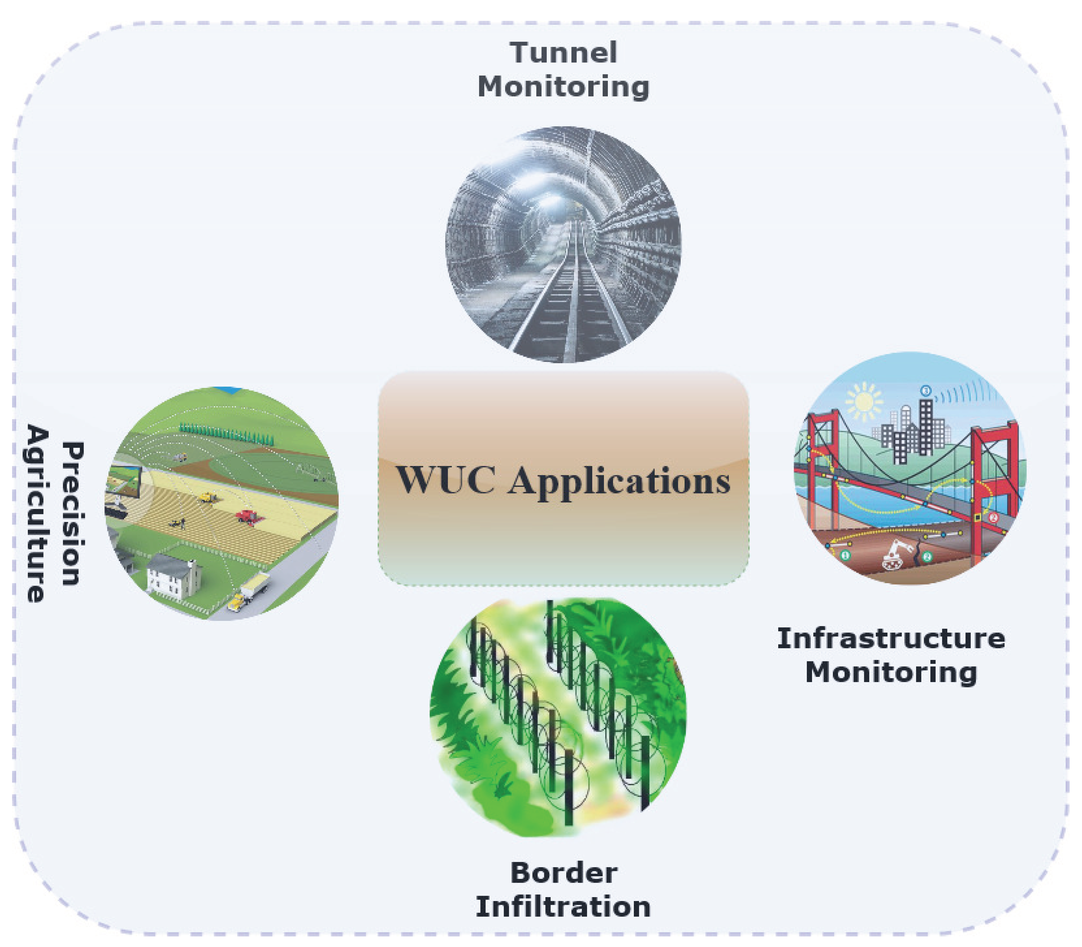
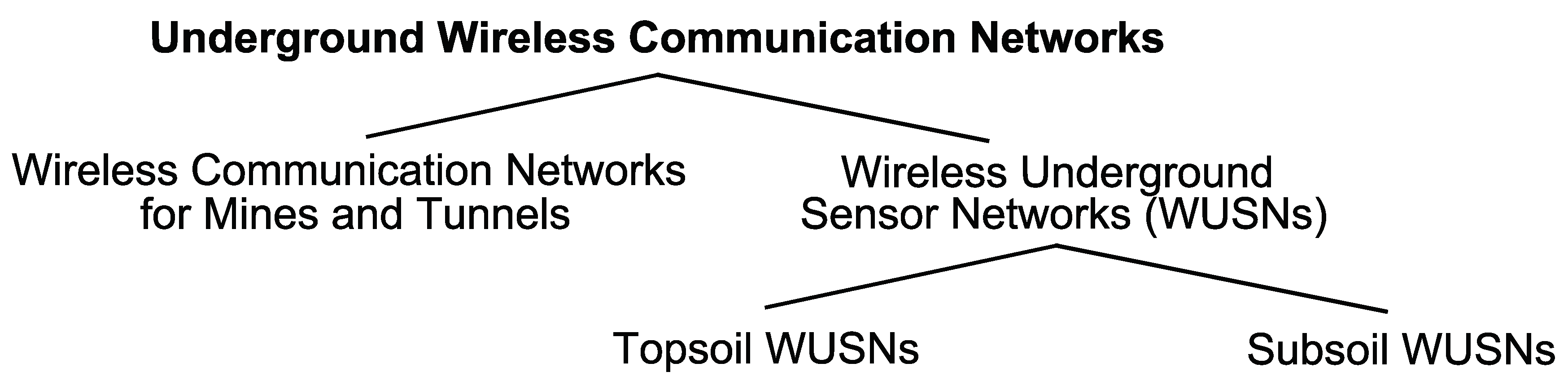
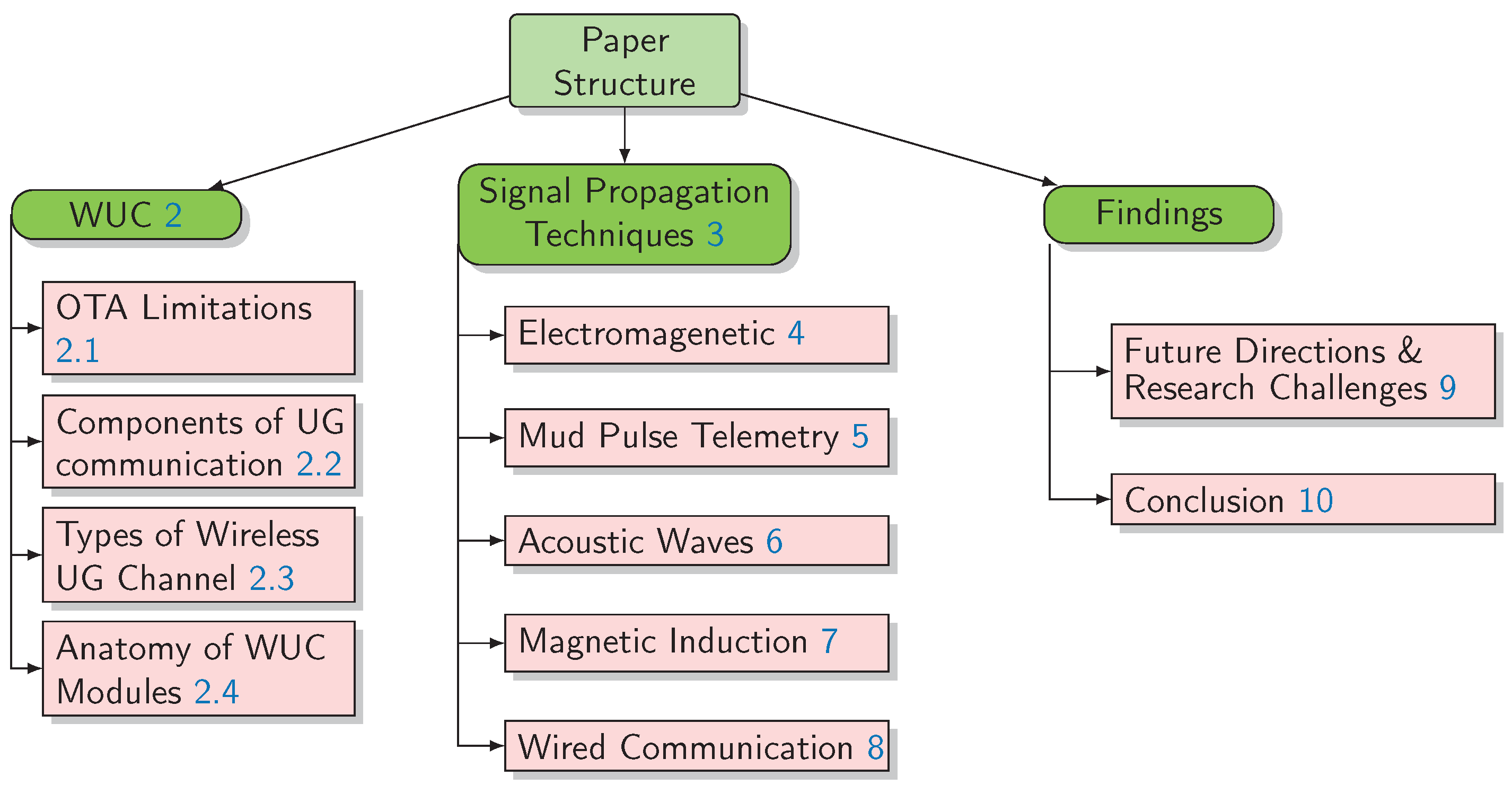
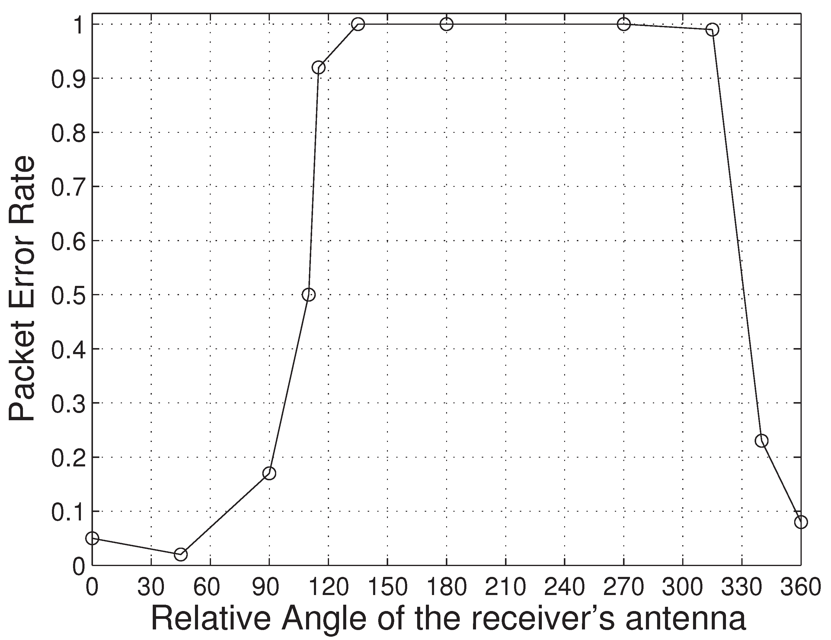
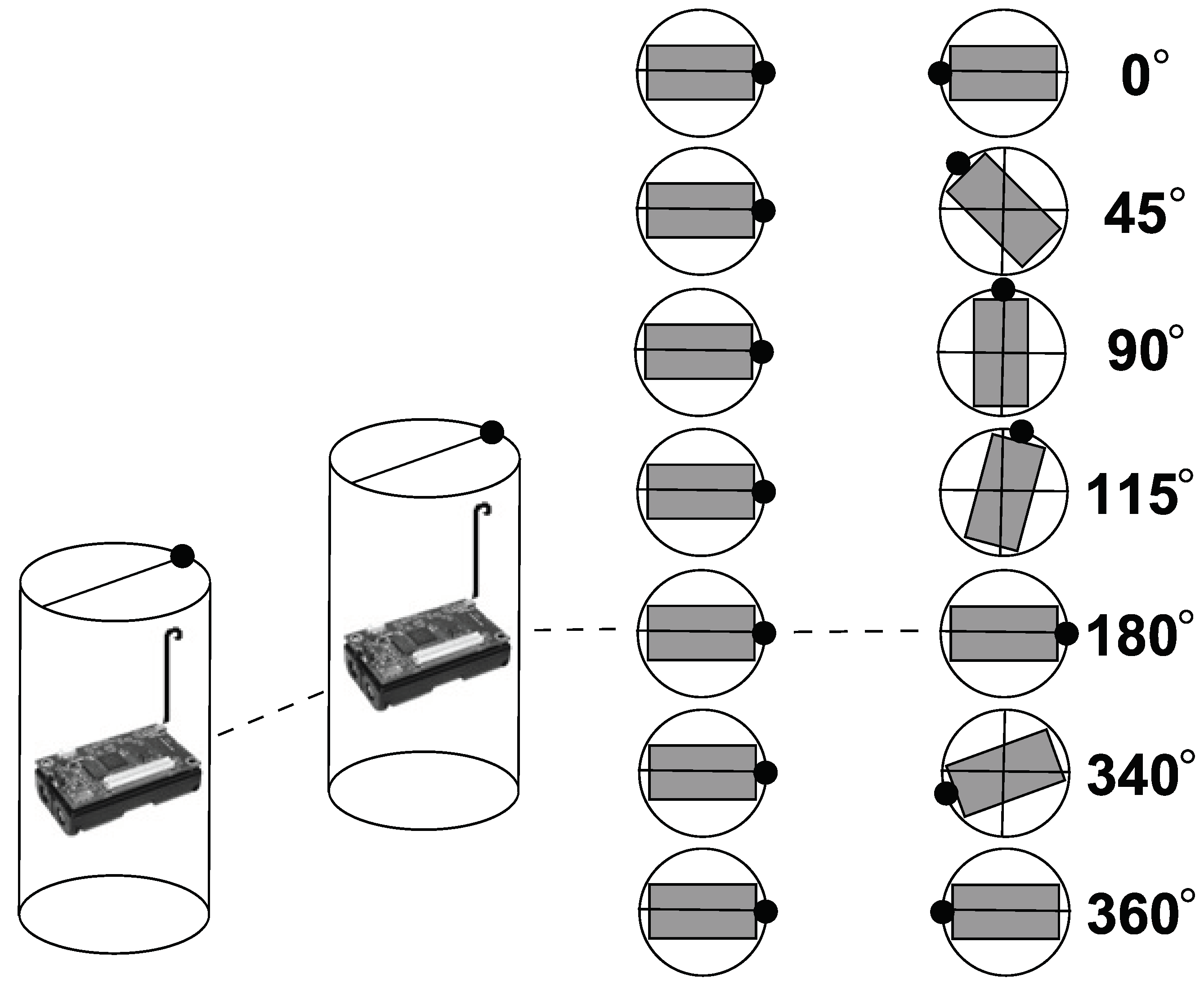
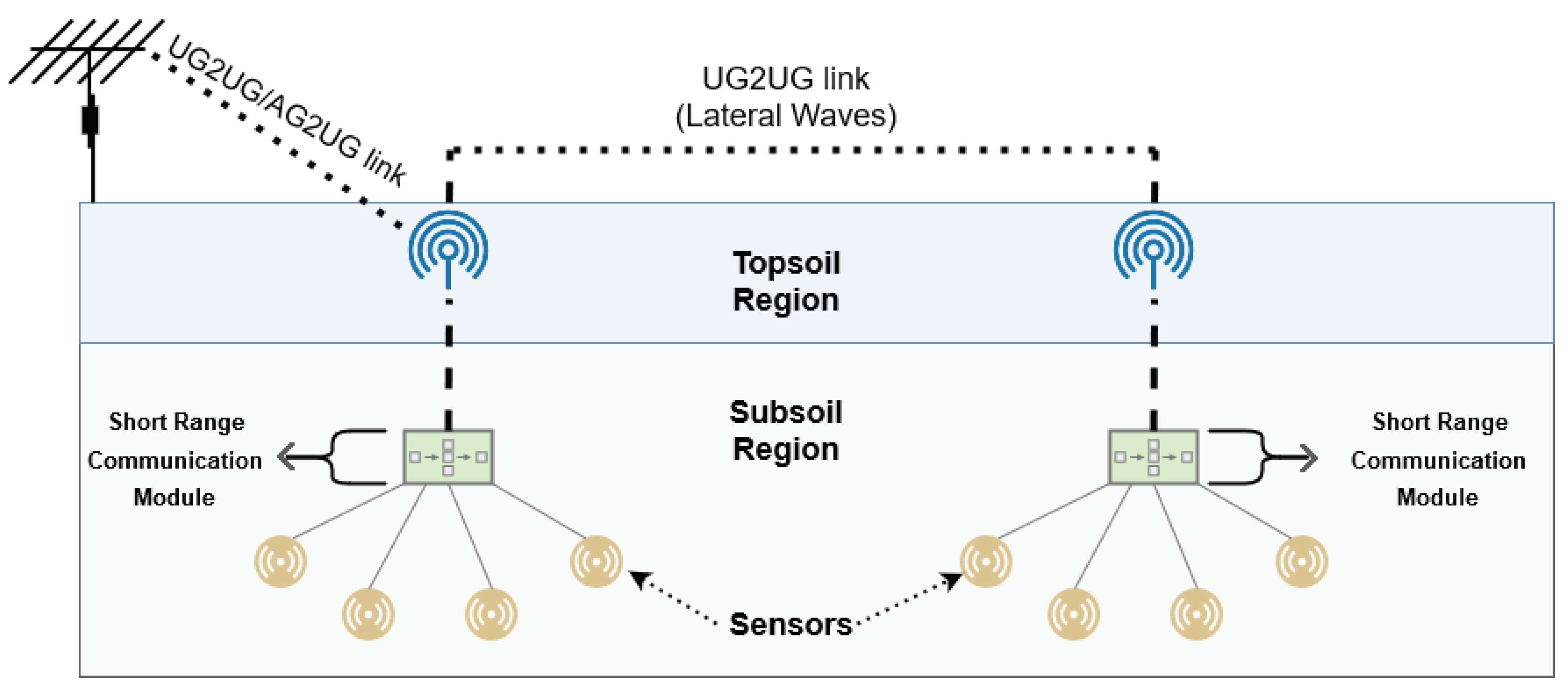
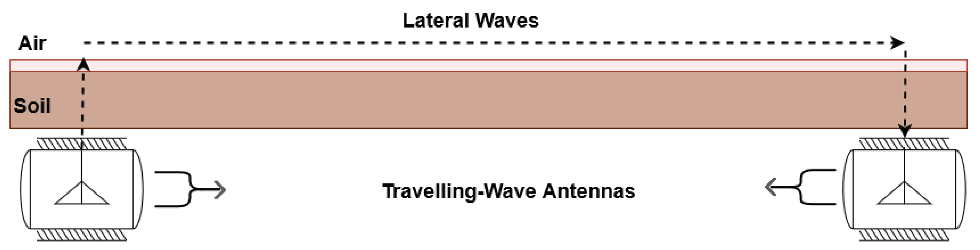
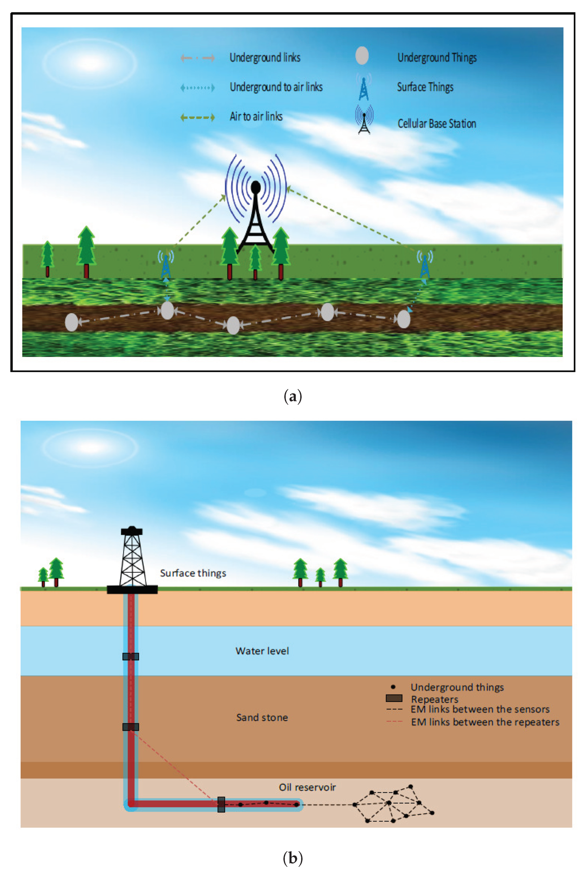
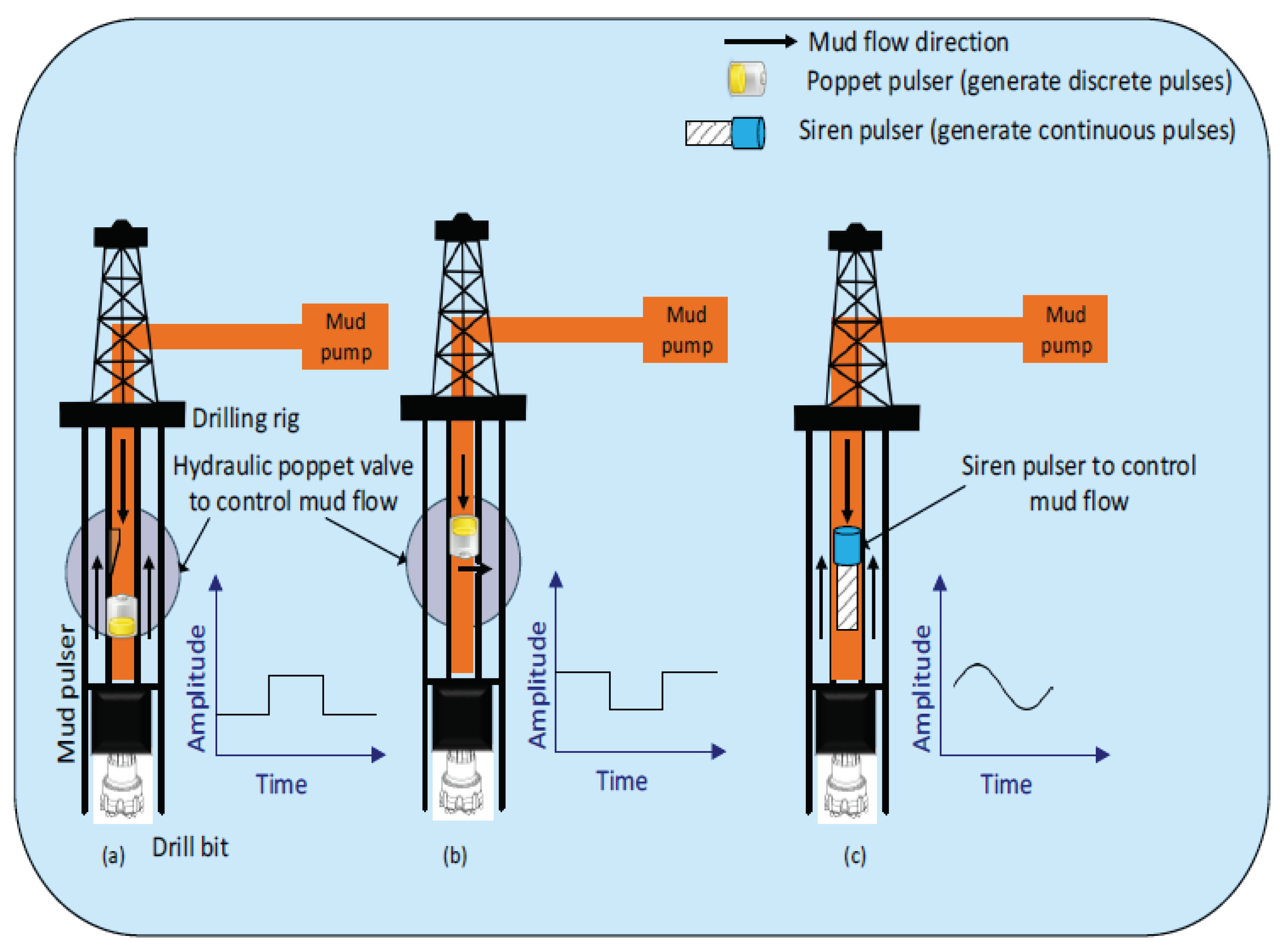
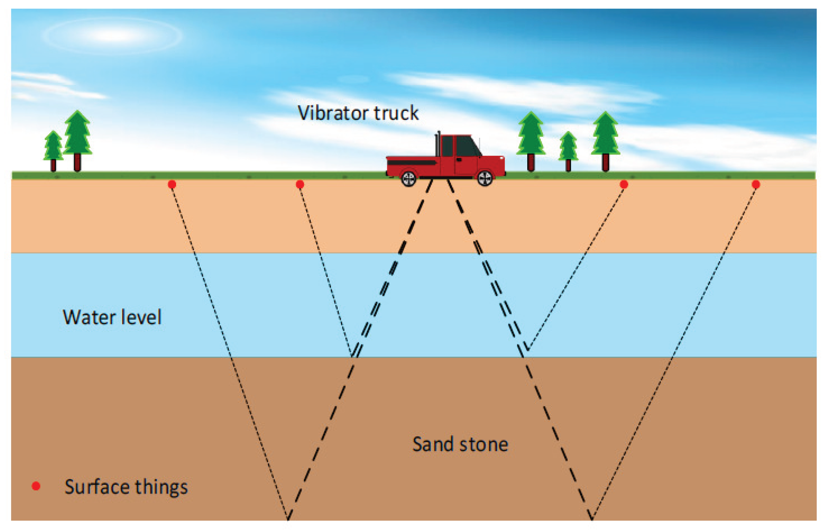
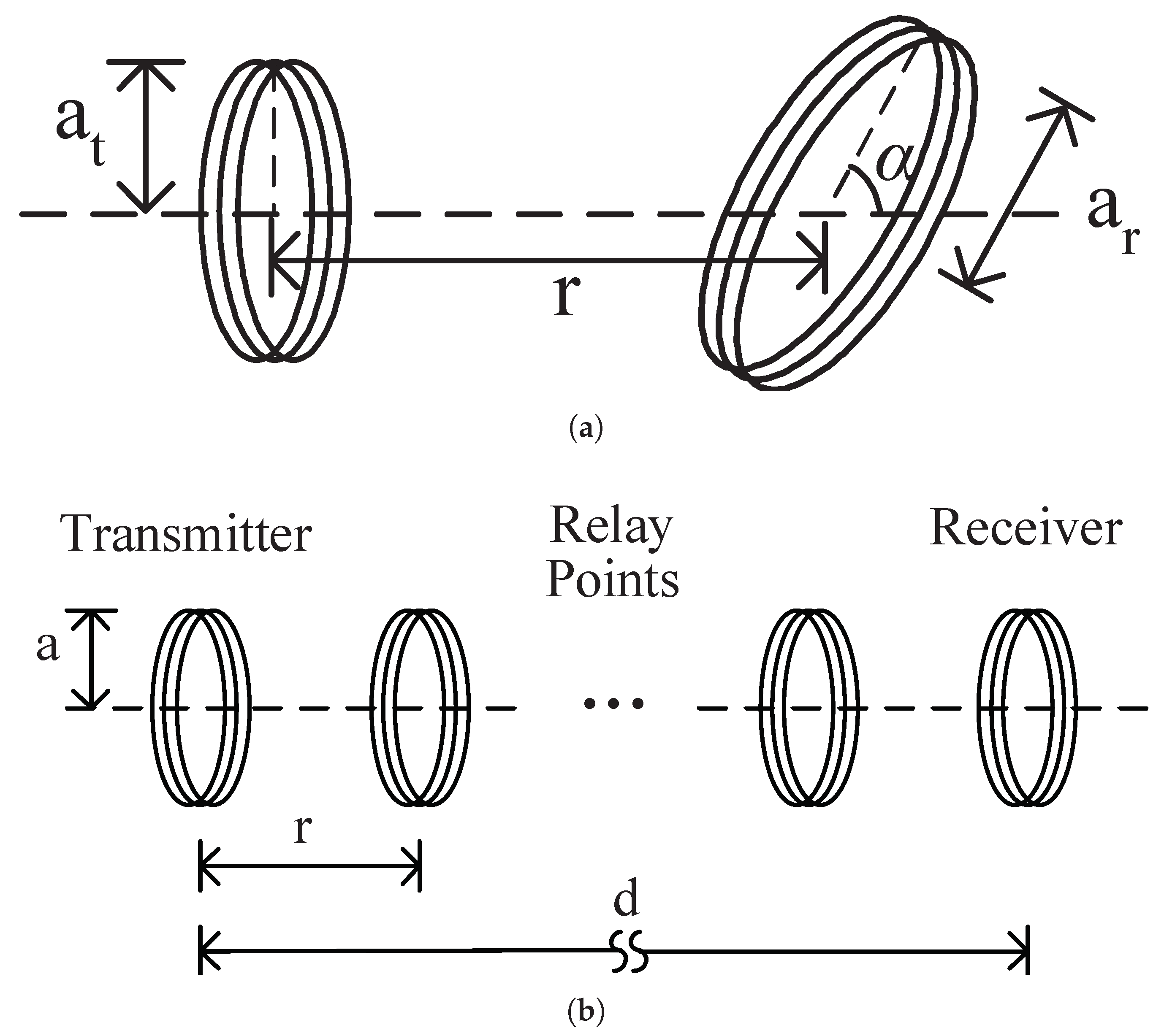
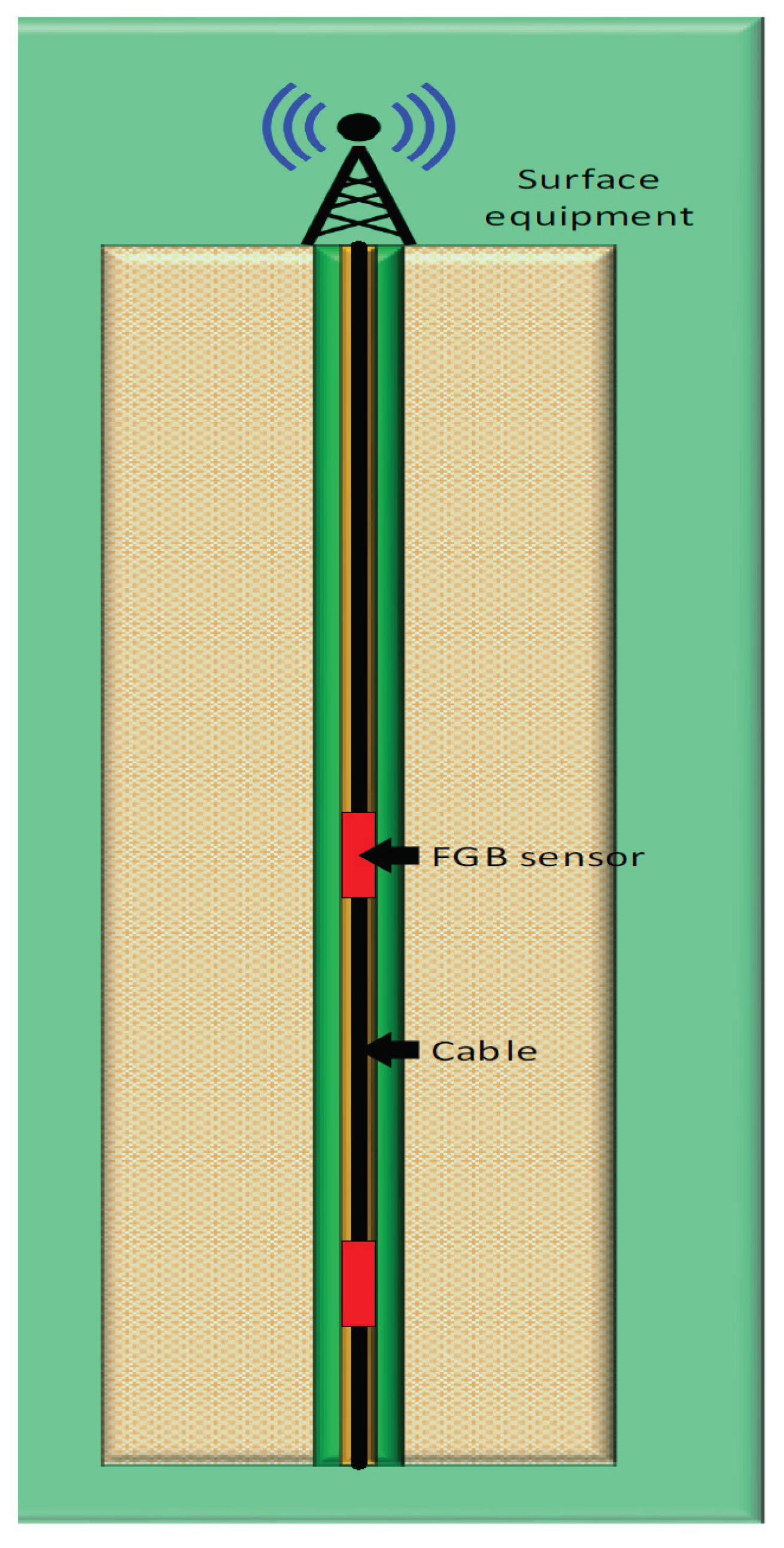
Table 1.
Typical aspects for Through-The-Earth (TTE) and WUC scenarios.
| Aspect | TTE-Based Communication | WUSN |
|---|---|---|
| Frequency range | VLF/LF | VHF/UHF |
| Maximum range (soil path) | Up to hundred meters | 5 cm to dozen meters |
| Bandwidth | Very small: bps | Small: Kbps |
| Network topology | One-hop | One-hop and multi-hop |
| Network density | Sender-receiver or few nodes | Hundred to thousand nodes |
| Underground channel noise | Very critical aspect | Small impact |
| Rock penetration | Feasible | Usually not feasible |
| Soil moisture | Small impact | Very critical aspect |
| Energy criticality | Relatively small impact | Very critical aspect |
| Node cost | Relatively high | Small |
| Communication protocol design | Emphasis on the physical layer | Cross-layer approach |
Table 2.
Summary of channel modeling for EM-based IoUT [182].
Table 2.
Summary of channel modeling for EM-based IoUT [182].
| Ref. | Data Rate | Frequency | Issue Addressed | Applications | Year |
|---|---|---|---|---|---|
| [164] | - | 1–10 MHz | Propagation characteristics | Seismic/Agriculture | 1971 |
| [165] | - | - | Structure of soil effect on EM waves propagation | Seismic/Agriculture | 1973 |
| [166,183] | - | 3–50 MHz | Electrical characteristics of soil | Seismic/Agriculture | 1974 & 1976 |
| [168] | 1–100 bps | - | EM waves for borehole communications | Oil & Gas | 1990 |
| [169] | - | 1–3 MHz | Impact of soil and network parameters | Agriculture | 1990 |
| [171] | - | 2–6 Hz | Investigation of depth on the signal strength | Oil & Gas | 2009 |
| [170] | - | 300–500 MHz | Impact of soil type | Agriculture | 2009 |
| [101] | - | - | Development of the path loss model | Agriculture | 2010 |
| [37] | - | - | Test-bed | Agriculture | 2010 |
| [174] | - | 0.3–1.3 GHz | Comparison of theoretical and experimental results | Agriculture | 2011 |
| [175] | - | 0.1–120 THz | Channel model | Oil & Gas | 2012 |
| [174,176] | - | below 500 kHz | Propagation characteristics | Agriculture | 2012 |
| [184] | - | 10–100 MHz | Energy harvesting | Seismic/Agriculture | 2012 |
| [177,178,179] | - | 433 MHz | Propagation characteristics | Agriculture | 2014–2016 |
| [180] | - | - | New transmitter and receiver configurations to improve the sensor node lifetime | Seismic | 2016 |
| [181] | - | 3.1–10.6 GHz | Impact of soil on ultrawideband underground to above-ground communication link | Agriculture | 2017 |
| [8] | 124 Mbps | 433 MHz | Multi-carrier modulation for EM-based IoUT | Agriculture | 2017 |
| [25] | - | 100–300 MHz | Using of the direct, reflected, and lateral components of the underground channel to improve the BER | Agriculture | 2017 |
| [185] | - | 433 MHz/2.4 GHz | Influence of depth on the propagation of EM signal | Agriculture | 2017 |
| [186] | - | 97–130 MHz | Soil moisture sensing | Agriculture | 2018 |
| [63] | - | 433 MHz | Estimation of relative permittivity and soil moisture | Agriculture | 2019 |
| [77] | - | - | Underground channel modeling by using Maxwell-Poynting theory | Agriculture | 2019 |
Table 3.
Existing Literature for MPT-based IOUT systems [182].
Table 3.
Existing Literature for MPT-based IOUT systems [182].
| Ref. | Frequency | Depth | Issue Addressed | Applications | Year |
|---|---|---|---|---|---|
| [192] | 10–12 Hz | 1.7 km | Generation, transmission, and reception of mud pulse signals | Deep water drilling | 2001 |
| [193] | 30 Hz | 0.5 km | Novel mud pulser which handle the varying nature of the channel | Oil & Gas reservoirs | 2008 |
| [194] | 40 Hz | - | Novel method by using a linear actuator to generate pressure pulses | Down-hole telemetry | 2008 |
| [201] | 12–24 Hz | 150 m | Adaptive noise cancellation technique for the mud pump | Underground Drilling | 2018 |
| [195] | 1–20 Hz | - | Novel decoding technique to overcome the pump noise, reflection noise, and random noise for MPT systems | Underground Drilling | 2007 |
| [197] | - | - | Down-hole noise cancellation | Underground Drilling | 2008 |
| [199] | - | - | Novel MPT system for under-balanced drilling | Underground Drilling | 2000 |
| [199] | 10–100 Hz | - | Investigation of the pressure wave propagation characteristics | Oil & Gas exploration | 2013 |
| [202] | - | - | Method to detect increase or decrease in the pressure for the MPT systems | Oil & Gas exploration | 2016 |
| [203] | 10–100 Hz | - | Novel hard rock drilling technique by using abrasive water | Underground Drilling | 2016 |
Table 4.
Comparison of acoustic waves-based IOUT [182].
Table 4.
Comparison of acoustic waves-based IOUT [182].
| Ref. | Data Rate | Depth | Issue Addressed | Applications | Year |
|---|---|---|---|---|---|
| [157] | 500 | 53.76 | Soil sampling | Agriculture | 2002 |
| [204] | - | - | Soil moisture detection | Agriculture | 2003 2004 |
| [158] | - | - | Down-hole communication | Underground Drilling | 2006 |
| [209] | 20 bps | 1120 m | Field tests for down-hole communication | Underground Drilling | 2007 |
| [205] | 20–60 bps | 1000 m | Soil moisture detection | Agriculture | 2010 |
| [219] | - | - | Detection of mines using acoustic waves | Underground mines detection | 2010 |
| [217] | - | - | Detection of rock deformation by using acoustic emission | Seismic | 2011 |
| [210] | - | - | Impact of pipe joints on signal transmission | Underground Drilling | 2013 |
| [212] | 6 & 20 bps | 55 & 45 m | OFDM for down-hole communication | Underground Drilling | 2013 |
| [220] | - | - | Impact of multi-phase flow with ASK and FSK | Underground Drilling | 2014 |
| [213] | - | - | Trellis coded modulation for down-hole communication | Underground Drilling | 2014 |
| [221] | 400 | 1000 | Universal soil loss equation | Agriculture | 2015 |
| [218,222,223] | - | - | Detecting cracks in pipelines | Underground pipelines monitoring | 2011 2015 |
| [215,224,215] | - | - | Investigation of single channel and multi-channel accelerometers | Down-hole telemetry | 2017 |
| [224] | - | - | NC-OFDM for down-hole communication | Underground Drilling | 2018 |
| [207,208] | - | - | Wireless data transmission in soil | Agriculture | 2018 |
Table 5.
Existing Literature addressing physical layer challenges in MI-based IOUT [182].
Table 5.
Existing Literature addressing physical layer challenges in MI-based IOUT [182].
| Ref. | Frequency | Issue Addressed | Design Aspect |
|---|---|---|---|
| [225] | 300 & 900 MHz | Underground channel modeling for MI | Channel modeling |
| [100] | 0.02 & 30 MHz | Use of tri-directional MI coils for omni-directional coverage and waveguides to improve the transmission range | Channel modeling and test-bed development design |
| [1] | - | Discuss various issues for underground MI-based communication | Cross-layer solutions |
| [98] | 10 & 300 MHz | Path loss and bandwidth analysis for underground MI communications | Channel modeling |
| [232] | 100 kHz | Path loss and capacity measurement for underground MI link | Channel modeling |
| [226] | - | BPSK, QPSK, and QAM for the underground MI links | Modulation schemes |
| [227] | 246 kHz | Use of pulse width modulation for underground MI-based communication | Testbed development |
| [228] | 246 kHz | Link budget calculation for underground MI link | Path loss modeling |
| [233] | 5 kHz | Impact of soil conductivity on the underground MI link | Channel modeling |
| [234] | 75 kHz–30 MHz | Soil path attenuation model and best frequency selection | Channel modeling and testbed development |
| [235] | 300–900 MHz | Improving transmission range by using relays and achieving higher voltage gain with multiple parallel receiver circuits | MI-based multi-hop underground communication |
| [229] | 20–50 MHz | Meta-material for coil design to improve transmission range and capacity | Coil Design |
| [230,231] | 10 Mhz | To study the impact of different medium on the MI link | Testbed Development |
Table 6.
Existing Literature addressing challenges of network layer in MI-based IoUT [182].
Table 6.
Existing Literature addressing challenges of network layer in MI-based IoUT [182].
| Ref. | Frequency | Issue Addressed | Design Aspect |
|---|---|---|---|
| [236] | 10 MHz | Improvement of the transmission range and robustness, and selecting optimal number of relays | Deployment strategies |
| [238] | - | Improvement of the transmission range by using relays and meta-materials | Multi-hop Networking/Hardware design |
| [237] | 300–900 MHz | Improvement of the transmission range by using relays | Deployment strategies |
| [238] | 10 kHz | Use of meta-material shell for the transceiver design to improve the received power | Transceiver design |
| [242] | - | Investigating the effect of coil orientation and polarization on the channel capacity | Interference minimization |
| [239] | 2 & 2.5 MHz | Throughput optimization | Multi-hop networking and interference minimization |
| [96] | - | Optimization of system parameters for multi-hop underground MI links | Maximizing the data rate |
| [97] | 7 MHz | Improving throughput, reducing energy consumption and time delay | Cross layer protocol |
| [240] | - | Throughput, delay, and energy consumption analysis | Cross layer protocol |
| [243] | 10 MHz | Transmission range enhancement by using meta-material based relay coils | Transceiver design |
| [241] | 300–1300 MHz | Connectivity analysis of multi-hop MI-based IOUT | Transceiver design |
Table 7.
Existing studies addressing localization in MI-based IoUT [182].
Table 7.
Existing studies addressing localization in MI-based IoUT [182].
| Ref. | Frequency | Issue Addressed | Dimensions | Applications |
|---|---|---|---|---|
| [246] | 130 kHz | Development of MI-based 2D underground tracking system | 2D | Tracking of underground animals |
| [247] | 125 kHz | Testbed for MI-based 3D underground tracking | 3D | Underground mining |
| [258] | 125 kHz | Testbed for MI-based 3D underground tracking | 3D | Underground rescue operations |
| [248] | 1 kHz, 100 kHz, & 10 MHz | Investigating the impact of minerals and rocks on the localization accuracy | 3D | Underground monitoring |
| [259,260] | - | Closed form solution for the distance estimation based on MI channel | 3D | Underground monitoring |
| [249] | 7 MHz | Using of semi-definite programming for MI-based underground localization | 3D | Oil and Gas reservoirs monitoring |
| [261] | 10 MHz | MI-based underground localization by using a single anchor node | 3D | Underground monitoring |
| [262] | 1 MHz | Machine learning approach for MI-based underground target localization | 2D | Underground rescue operations |
| [257] | 7 & 13 MHz | Analytical expression for the achievable accuracy of MI-based underground communications | 3D | Oil and Gas reservoirs monitoring |
Table 8.
Existing studies addressing wired communication solutions for IOUT [182].
Table 8.
Existing studies addressing wired communication solutions for IOUT [182].
| Ref. | Type | Issue Addressed | Application | Year |
|---|---|---|---|---|
| [94] | Optical fiber | Study on the use of optical fiber for Oilfield industry | Oilfield monitoring | 2002 |
| [95] | Coaxial cable | Development of high speed down-hole communication system | Down-hole telemetry | 2008 |
| [265] | Optical fiber | Down-hole communication temperature sensing | Management of oil reservoirs | 2010 |
| [266] | Coaxial cable | Down-hole communication in the presence of high pressure and high temperature | Management of oil reservoirs | 2013 |
| [267] | Optical fiber | Discussion on various applications of fiber optic sensing | Underground monitoring | 2018 |
| [268] | Optical fiber | Development of fiber optic based down-hole telemetry system | Down-hole monitoring | 2001 |
| [269] | Optical fiber | Review of fiber Bragg grating sensors for down-hole monitoring | Down-hole monitoring | 2000 |
| [273] | Optical fiber | Field tests by using FBG-based seismic geophones | Oil & Gas reservoirs monitoring | 2007 |
| [271] | Optical fiber | Multiplexing of temperature and pressure FBG sensors | Oil & Gas reservoirs monitoring | 2012 |
| [274] | Optical fiber | FBG sensors-based testbed development | Geophysical observations | 2015 |
Table 9.
Research challenges for IOUT applications.
| Research Challenge | Agriculture | Seismic Exploration | Oil & Gas |
|---|---|---|---|
| Deployment | Medium | High | High |
| Channel modeling | Medium | Medium | High |
| Transmission range | Low | High | Medium |
| Latency | Low | Low | Medium |
| Reliability | Low | Medium | High |
| Security | Medium | High | High |
| Scalability | Low | Medium | Medium |
| Robustness | Low | Medium | High |
| Networking | High | Medium | Medium |
| Cloud computing | High | Medium | Low |
| Fog computing | Low | Medium | High |
| Localization | Medium | High | Medium |
Publisher’s Note: MDPI stays neutral with regard to jurisdictional claims in published maps and institutional affiliations. |
© 2020 by the authors. Licensee MDPI, Basel, Switzerland. This article is an open access article distributed under the terms and conditions of the Creative Commons Attribution (CC BY) license (http://creativecommons.org/licenses/by/4.0/).
Share and Cite
MDPI and ACS Style
Raza, U.; Salam, A. A Survey on Subsurface Signal Propagation . Smart Cities 2020, 3, 1513-1561. https://0-doi-org.brum.beds.ac.uk/10.3390/smartcities3040072
AMA Style
Raza U, Salam A. A Survey on Subsurface Signal Propagation . Smart Cities. 2020; 3(4):1513-1561. https://0-doi-org.brum.beds.ac.uk/10.3390/smartcities3040072
Chicago/Turabian StyleRaza, Usman, and Abdul Salam. 2020. "A Survey on Subsurface Signal Propagation " Smart Cities 3, no. 4: 1513-1561. https://0-doi-org.brum.beds.ac.uk/10.3390/smartcities3040072