Research on Increasing the Performance of Wind Power Plants for Sustainable Development


1
Faculty of Technological Engineering and Industrial Management; Transilvania University of Brasov, 500222 Brasov, Romania
2
Faculty on Engineering and Management of Technological Systems; University Polytechnic of Bucharest, 060040 Bucharest, Romania
*
Author to whom correspondence should be addressed.
Sustainability 2019, 11(5), 1266; https://0-doi-org.brum.beds.ac.uk/10.3390/su11051266
Submission received: 20 November 2018
/
Revised: 8 February 2019
/
Accepted: 11 February 2019
/
Published: 27 February 2019
(This article belongs to the Special Issue Sustainable Energy Systems: From Primary to End-Use)
Abstract
:A topical issue globally is the development and implementation of renewable energy sources for sustainable development. To meet current requirements, the research in this paper is directed towards finding solutions to increase the performance and efficiency of wind power plants by implementing innovative solutions for hollow roller bearings developed through the use of sustainable growth programs in the field of green energy. Another solution that has the effect of increasing wind power performance consists of the implementation of a new large-size lubrication system for large-size bearings in wind energy units, which will increase their durability by developing maintenance capabilities. In this research, we will explore the possibility of introducing an innovative automated lubrication system in hollow roller bearings. The main results of the research, the innovative constructive solutions, will lead to important savings by lowering wind farm maintenance costs, increasing the durability of large bearings, and increasing the energy efficiency and yield of the whole system. The expected impact of implementing the solutions found will mainly be in the field of sustainable growth and environmental development.
1. Introduction
Wind power is currently one of the most important alternative sources of renewable energy, offering the major advantage of zero emissions of greenhouse gases by reducing and even eliminating the use of fossil fuels. By developing the wind energy sector as the energy of the future, environmental and sustainable development requirements will be met while achieving energy security objectives. Implementation of wind power projects aiming at building wind turbines that produce more energy, thus reducing costs in the context of sustainable development, has been a major concern in recent years.
Over the years, researchers have consistently sought new ways of making wind turbines more and more eco-friendly [1]. Research in recent years has provided an overview of different solutions to develop a new generation of wind turbines, and feasible and technological trends in wind power generation that could reduce costs. The need to use renewable energy, as well as a review of various wind technologies in connection with their applications and operating devices, is detailed in this paper [2]. It is demonstrated that the cost of generating electricity, as well as the current economic and environmental policies, supports the installation and development of wind power systems. This paper provides arguments on the usefulness of this research in the development of wind assemblies. In [3], some technological solutions regarding the power electronics in the wind turbine systems are presented. The paper provides an overview of the state of the technology and discusses the technological trends in the field. There are also some difficulties that arise in the operation of the control part, generators and gearboxes, where the main components are known to be bearings. It is necessary to find solutions to improve the operation and reliability of wind turbines, and the solutions proposed in the present paper follow this direction. Another technical solution, consisting of the implementation of a new concept, “the adaptive-blade concept in wind-power applications”, is presented in [4]. One of the technological challenges in the wind energy field is the development of a new generation of feasible, improved turbines, which further reduce production costs. As the size of the typical turbine increases, weight reductions, as well as complexity in the design of rotors and their auxiliary mechanisms, are becoming increasingly important. The study proposed for reducing inertial masses by implementing large bearings with hollow rollers is of great interest. After some research on the reliability of wind turbines [5], analysis of the failure modes, and causes of defects, it was found that the highest failure rate occurs in some key components of the wind turbine assembly, including the generator, gearbox and blades. Transmission and generator faults are mainly caused by bearings. Ref. [6] discusses the analysis requirements for the design and operation of the main bearings in modern multi-megawatt wind turbines, with a view to finding technical solutions for bearings with high reliability and profitability.
Wearing processes considerably reduce the precision and durability of bearings [7]. In this paper, an analysis is carried out of bearing failures caused by wear. The presence of different types of wear and the detection of bearing defects are studied. The bearing elements (inner and outer rings, rollers) are put into operation with complex loads, such as: high strains and alternating stretch and compression, rolling friction, abrasive friction and corrosion.
Worldwide, in the field of large-sized bearings, studies only began relatively late (1970–1975), compared with studies in the field of small- and medium-sized bearings. In countries with bearing manufacturing traditions (USA, Japan and Germany), a great deal of research on large bearings has been seen in the last decade. It has been found that wind turbine generator bearings have a surprisingly high failure rate, with failures happening too early due to classical rolling contact fatigue [8]. Reference [9] studies the behavior of the bearings in the gearbox of a wind turbine and the impact on its reliability. Inertial forces on small- and medium-sized bearings do not have the negative effects that they have on large-sized bearings.
Today, all the construction solutions for wind turbines use large roller bearings with solid rollers, with expensive logarithmic profiles to reduce contact pressures and increase resistance under variable load conditions [10,11]. Based on all of this research, this paper proposes new technical solutions for improving the lifespan of wind turbines, especially the large-sized bearings inside the gearing system, by implementing an automated lubrication system in the hollow rollers. Following previous studies by the authors [12,13,14], a solution to using hollow roller large bearings in the construction of wind power plant assemblies is proposed.
The proposed solution using hollow rollers requires only a cylindrical profile (easy to obtain) with a similar behavior to the solid rollers with a logarithmic profile. Due to the weight of the rollers, inertial masses have been widely investigated, with the use of hybrid or ceramic bearings being proposed [15]. Their high cost requires new research on the reduction of inertial masses of large-size bearings. Attempts have been made to reduce the negative influence of centrifugal loads by decreasing the density of the rolling elements, in turn achieved by using lower density materials.
There are constructive solutions that have adopted drilled or hollow steel rolling elements [16,17], but these are not intended for the construction of large-size bearings for wind turbines. A solution for determining the size of the hollow roller was described in [18]. The analysis has shown that the durability of hollow cylindrical roller bearings operating at the maximum allowable stress level can be substantially higher than the durability of solid roller bearings.
After analyzing the specialty literature, it was found that there is no standard method for calculating the optimal hollowness of hollow roller bearings. This depends mainly on the applied load, and the size and the material of the roller. The use of hollow rollers in large bearings has some advantages over the solid rollers. These include reducing the material used in roller making, reducing the weight of the roller bearing, and attaining the preloading capability of the hollow cylindrical element, thus generating more stability, and less noise and vibrations. Hollow roller bearings are single- or double-row radial bearings with an inner ring, outer ring, and cylindrical or thin wall rollers. The thin wall of the rollers allows preloading, as opposed to cylindrical bearings with solid rollers. Preloading rollers on large bearings with hollow rollers increases radial stiffness and reduces vibrations [19].
On the other hand, major problems in the operation of a wind turbine occur in the lubrication of the bearings. Appropriate lubrication is essential for the correct operation and lifespan of the bearing. Existing lubrication system automation involves expensive and complex solutions [20], or solutions that require highly qualified personnel and maintenance stops for wind farms. Operation and maintenance costs are estimated to reach up to 30% of the total lifecycle expenditure [21]. The proposed lubrication system is inexpensive, and easy to carry out and maintain.
Reducing subsidies in this area transforms this topic into a mainstream one, as it leads to important savings by lowering the cost of maintenance of wind farms by increasing the durability of large bearings, as well as by increasing the energy efficiency and yield of the whole system. The expected impact of the implementation of hollow roller bearings and the automated lubrication system is important in times of economic crisis, mainly in the area of sustainable growth.
1.1. Wind Energy, Strategies and Directions of Development
The wind power industry has grown greatly around the world, and is among the green energy resources. The use of wind energy has increased nearly four times between 2004 and 2015 and currently accounts for about one third of renewable electricity. The use of terrestrial wind energy is quite close to the anticipated trajectory over the years [22]. The Global Wind Energy estimation [23] explores the future of the wind energy industry by 2020, 2030 and by 2050. Several scenarios have been developed by the International Energy Agency [24]. Based on the advanced scenario, GWEC estimates that by 2050, global wind power will reach 5806 GW (Table 1).
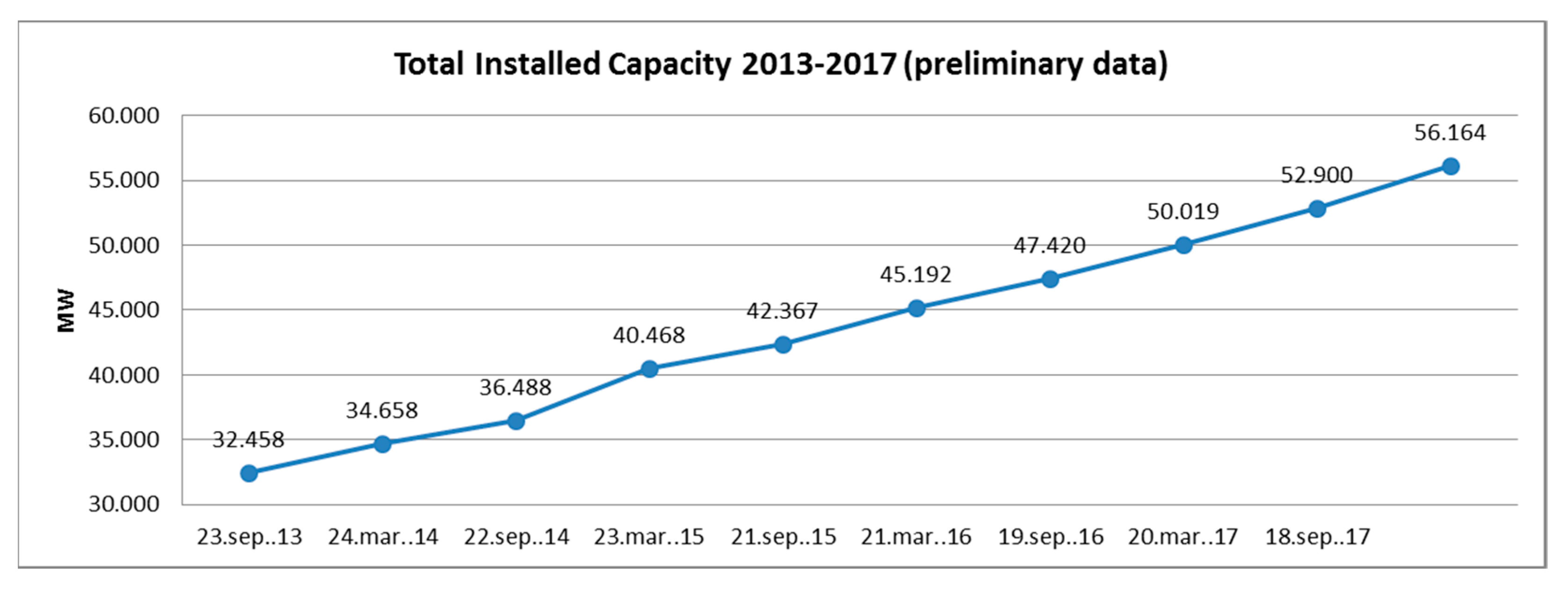
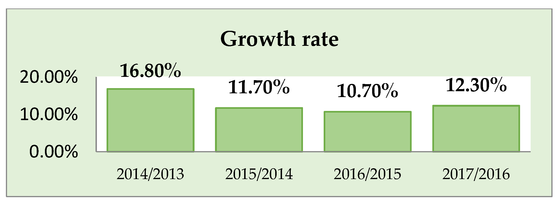
At the end of 2016, in the Global Wind Energy Council Report [23], 341.320 wind turbines were catalogued as being in operation, of which 104.934 were in China, 52.343 were in the USA, and 3589 were offshore wind turbines in Europe at the end of 2016. The evolution of the total capacity of all wind turbines installed worldwide during the period 2013–2017 is presented in Figure 1, according to preliminary World Energy Association (WWEA) statistical data [25]. Thus, in 2017, a capacity of 6145 MW was installed, with a growth rate of 12.30% compared to the previous year (Figure 2), representing a revival.
Many countries have based their strategies of phasing out fossil and nuclear energies on the development of wind power energy sources. A recent study in the specialty literature [26] presents the current state of lifespan extension of offshore wind turbines in Germany, Spain, Denmark and UK. According to [23,27], among the top 20 countries in total wind power capacity in 2017, the fastest growth of new facilities was found in the United Kingdom (+4.3 GW/+29.2%), Brazil (+2.0 GW/+18.8%), Ireland (+0.4 GW/15.8%), India (+4.1 GW/+14.5%) and France (+1.7 GW/+14.0%). Year 2017 was a spectacular year in the field of wind energy generation, with Denmark setting a new world record, with 43% of its power coming from wind. Countries like Germany, Ireland, Portugal, Spain, Sweden or Uruguay have reached a double-digit electricity share, as shown in the WWEA Report [25].
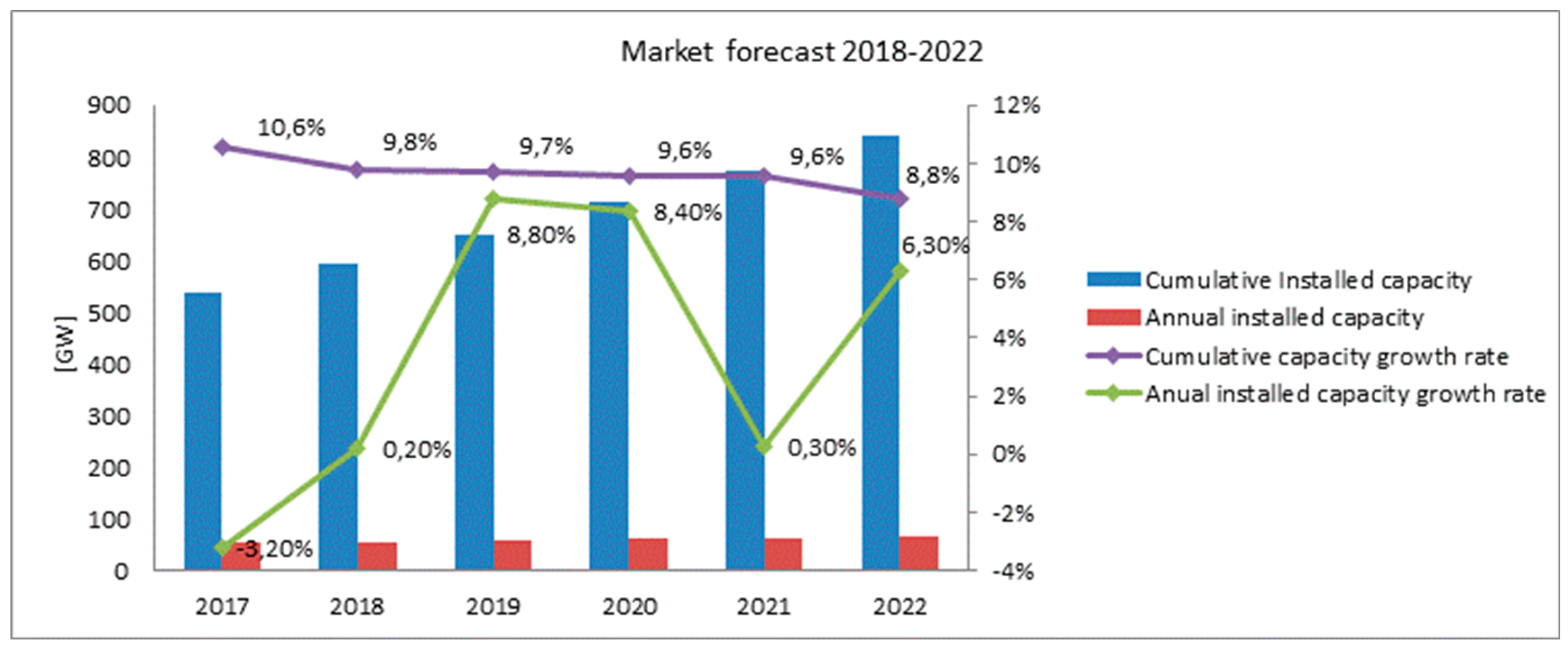
The Global Wind Energy Council (GWEC) considers, based on market statistics for February 2018, that wind energy has a major role to play in the sustainable development, “wind is the most competitively priced technology in many if not most markets, and the emergence of wind/solar hybrids, the more sophisticated grid management and the increasingly affordable storage, begin to paint a picture of what a fully commercial fossil-free power sector will look like [23].” Cumulative total installations are expected to reach 840 GW by the end of 2022 (Figure 3, [23]).
For the European Union, combating climate change is an important objective to ensure sustainable development. The measures taken by the EU to meet this main target, as well as the necessary activities in this area, both for the next period up to 2020 and for the period after 2020, are detailed in the GWEC Report [23]. Thus, it is considered that “Europe is expected to align with its 2020 targets, and current discussions within the EU indicate that overall renewable targets could be raised to 35% by 2030, putting the industry in a position stronger for the post-2020 market. In Europe, it is expected to install 76 GW of new wind power energy by the end of 2022, reaching a cumulative total of 254 GW”.
1.2. Wind Energy Potential in Romania
To make the EU a truly smart and sustainable low-carbon economy, the European Commission and the member states need to work together to use renewable energies. The strategy of the European Union and its member states on wind energy development consists of “stepping up urgent efforts to use wind energy as part of a global strategy for renewable energy and to develop a roadmap for a future 100% renewable energy”, as highlighted in the (WWEA Report, 2018) [25]. The adoption of the “Clean Energy for All Europeans” package of measures aims to maintain the EU’s competitiveness as the transition to clean energy changes the world’s energy markets [28,29].
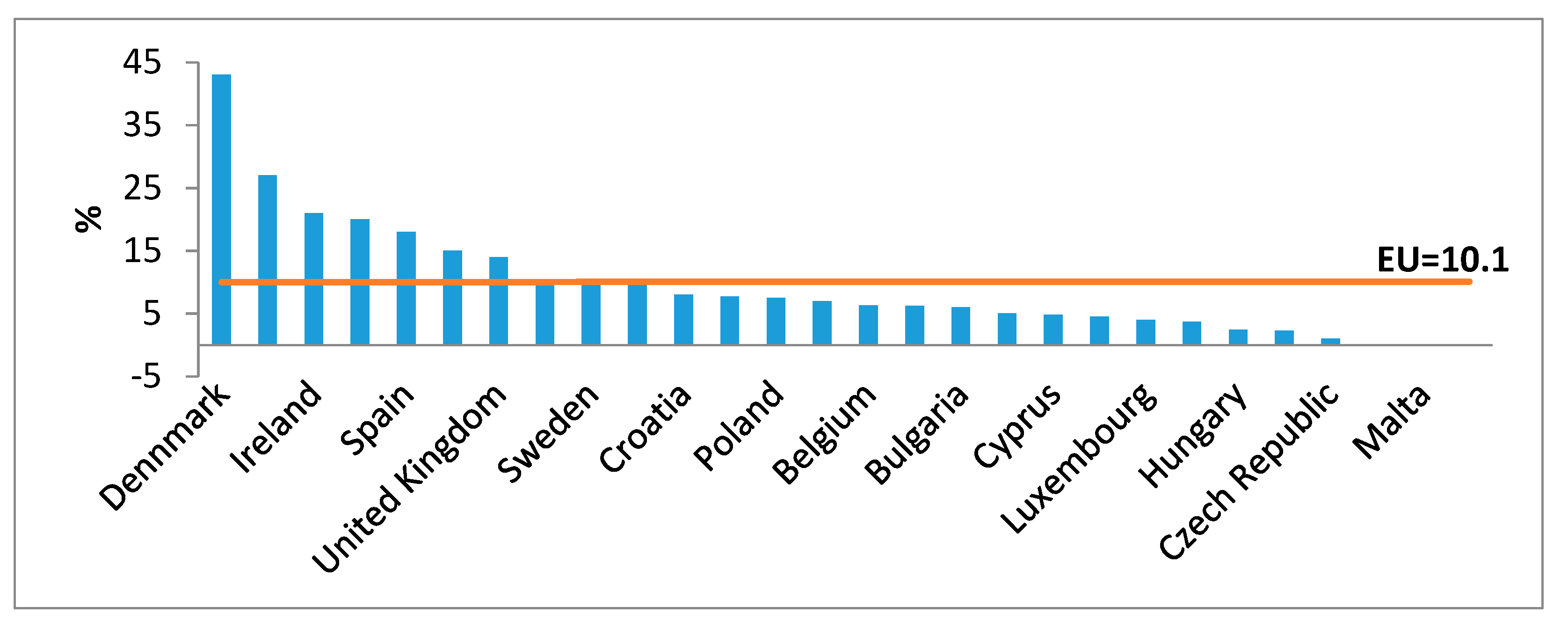
Currently, in Romania, wind energy has priority development through national strategies for sustainable development by 2030 and 2050 [30,31]. Recent Eurostat statistics for 2017 [32] highlight the efficiency of wind energy implementation in the EU Member States. Thus, at the end of 2016, EU wind turbines generated 315.00 GWh of electric energy (equivalent to more than 10% of the 3.1 million GWh produced in the EU). Denmark ranks first (43%), and is followed by other countries: Ireland (21%), Portugal (20%), Spain (18%) and the United Kingdom (14%). Romania, with a rate of about 10%, ranked tenth (Figure 4).
Regarding Romania’s wind energy, five wind zones were identified, depending on the environmental, topographical and geographical conditions, taking into account the level of energy potential of such resources at an average height of 50 m and over. The results of recorded measurements show that Romania is in a temperate continental climate with a high energy potential, especially in the coast and coastal areas (mild climate), as well as in alpine areas with mountain plateaus and peaks (severe climate). Based on the evaluation and interpretation of recorded data, it is possible to conclude that in Romania, the wind energy potential is most favorable on the Black Sea coast, in the mountain areas and plateaus in Moldova or Dobrogea.
Measures performed in our country demonstrate a high wind capacity, confirming that Dobrogea is, along with northern Scotland, the most promising wind exploiting region in Europe, according to the Romanian Wind Energy Association (RWEA) specialists. In the RWEA Report [33], “Wind Energy and Other Renewable Energy Sources in Romania”, there are areas (Scotland, Iceland, Denmark, Costa Rica, Tasmania, Australia) that have planned different deadlines for full reduction of carbon emissions and the development of programs to ensure green energy independence for the period 2020–2030. On 1 January 2017, Romania recorded 3025 MW in investments of over 5 billion EUR. Today, our country numbers 20 large wind farms, ranging from 70 MW up to 600 MW of installed power. Romania sources 12.3% of its electricity consumption from wind power [34].
Analyzing the widespread use of wind energy in Romania, the proposal to implement a completely new automated lubrication system positioned in the hollow rollers of large bearings is, from an economic and technical point of view, one of major interest with respect to the sustainable development of the green energy field.
2. Materials and Methods
Renewable energy sources are playing a major role in turning the EU into a world leader in innovation, with the EU owning 30% of all world-wide patents on renewable energy [22]. In the field of wind energy generation, a significant part of the cost reductions can be achieved through technological improvements and the implementation of innovative solutions that lead to sustainable development.
This research was conducted in two stages. In the first stage, the design of the hollow rollers was carried out using the finite element analysis method applied by established software, Nastran and Catia, and validation was done through direct measurement. The results consisted of studying the distribution of stresses and deformations in the rollers and bearings. The second stage was the designing, developing and testing of a prototype lubrication system implemented in the hollow rollers of large bearings.
Large-size bearing modeling has become a mandatory issue, precisely because of its size. Reducing inertial masses on these bearings would be a leap forward across the whole bearing industry. Referring to the product catalogues of the leading bearings companies (SKF, TIMKEN [35,36], INA, FAG [37,38]), cylindrical, conical or barrel roller bearings were identified in sizes up to 7 m and weighting several tons. All of these bearings have massive rollers—solid, large masses, with high inertial moments, which are disadvantages. The implementation of hollow roller bearings in wind power plants responds to the two major problems encountered in the operation of wind farms: increasing lifespan and increasing energy yield.
At present, the lifespan of a turbine is approximately 20 years, with 1/3 of this time being scheduled for maintenance. Maintenance costs increase with the age of the wind farm. According to WMI—Wind Measurement International [39]—a first-generation turbine has a maintenance cost of about 3% of its initial value; currently, this cost is falling to about 1.5%. Reduction of maintenance time can be done by increasing turbine durability to external factors: wind turbulence, variable air density, humidity, salinity, temperature. It has been found that the resulting defects lead to a 10% reduction in produced energy [40], and half of these are due to defects in bearings. All wind turbines have their own wind measuring devices and, based on the information gathered by them, the computer itself makes the adjustments necessary for optimal operation without the need for a human operator to be present at all times. The wind turbines include remote means of verification and remote control, thus making management of production units easier. Since this is an installation with moving parts, wear and maintenance costs will occur [35,36].
2.1. Operating Principle of a Wind Turbine
The system describing the operation of a turbine is based on a simple principle. The wind moves the blades that, in turn, actuate the electric generator. The mechanical system [41] includes a speed multiplier that directly operates the central shaft of the electric generator.
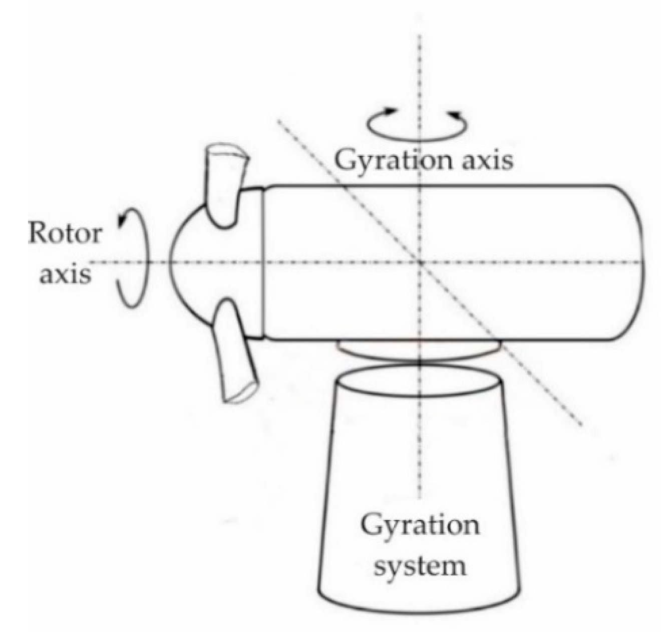
Figure 5 shows the main rotation movements of a horizontal wind turbine; the pivot system can be seen to feature a large bearing.
The electrical current obtained is either transmitted for storage in batteries and then used by an inverter for low-capacity turbines or delivered directly to the AC network for distribution. The turbine that drives the electric generator is also driven by the wind pressure. The amount of electricity produced by a wind farm depends on the type and size of the turbine and the location of the farm. At low speeds, it does not generate electricity. From Beaufort 2 (about 3 m/s) onward, the turbine delivers its maximum power. At a wind speed of over 25 m/s, the turbines are designed to lock and brake in a controlled way to avoid overloading and damaging the turbine installation or construction. The latest developments are equipped with a tilt angle control device that changes the angle of the rotor blade under unfavorable weather conditions [42].
Wind turbines are equipped with a robust safety system including an aerodynamic locking system. In case of danger, or for shutdowns needed in maintenance, a locking disc is used. The rotation systems that actuate the electric generator have roller bearings provided with logarithmic profile rollers on which carburetor thermal treatment is made at high depths of 7–10 mm [12].
Reducing roller masses directly reduces inertial moments, increasing start-up speed, offering easier handling of the plant, reducing static load in the bearing, and reducing vibrations. The influence of inertial masses in the wind turbine construction, implicitly in the construction of large-size bearings, is studied by Song, Dhinakaran and Bao [43].
2.2. Logical Scheme for Choosing the Optimal Construction Solution for Large Bearings
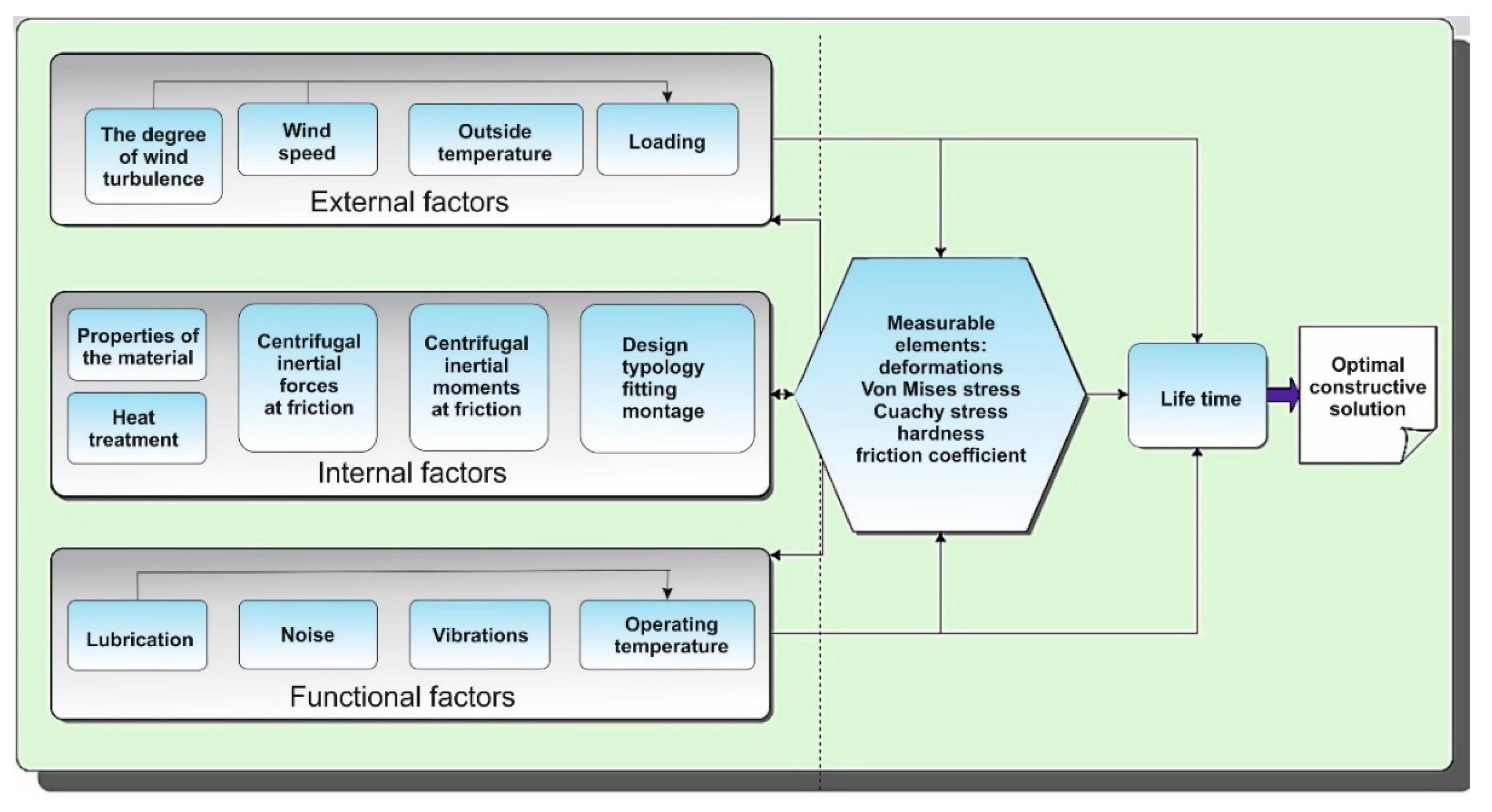
Figure 6 illustrates the logical scheme of the interaction of influence factors in the operation of large-size bearings. Each category of factors interacts and influences the end point of the logic scheme, namely the duration of operation. Both the static load created by the bearing construction and the dynamic load due to the external wind conditions directly determine the contact stresses, hence the deformations. The roller construction, material conditions and thermal treatment are designed to counteract the negative effects of variable loads, and the temperature generated by additional frictional forces.
An appropriate lubrication system, reducing loads by reducing inertial masses, as well as faster and clearer system response to external disturbances, is a result of using hollow roller bearings in the construction of large-size bearings. Generally, when studying a bearing, the lifespan of the bearing and the system in which it is mounted are studied. In the analysis of a bearing, dynamic loading is an essential element in its definition and mathematical modeling. Dynamic loading occurs between rolling elements and rolling treads due to the movement of the rolling elements, both the movement around the bearing axis and the movement around its own axis. These movements at higher or lower speeds, depending on the use of the bearing, generate forces that interact and produce stresses between rolling elements and rolling treads.
Controlling the stresses that appear on the surface of the rolling elements leads to increased lifespan and improved bearing efficiency. In the case of large cylindrical roller bearings, due to their mass, the stresses are higher and generate significant defects and high maintenance costs.
3. Results
The aim of this research is to implement the constructive solution of hollow rollers in the construction of large-size bearings for wind power plants. Hollowness, size and shape are features that are optimized, starting from the basic necessity of complying with the initial functionality. Studies in [12] on the behavior of hollow rollers confirmed the advantages of their use in the construction of large-size bearings, mainly for use in the wind energy industry.
3.1. Finite Element Analysis Model of Hollow Rollers
Choosing an optimal constructive variation is influenced by internal, external and operating factors, as previously presented (Figure 7). Their influence is quantified and measured by using Finite Element Analysis—FEA (Von Mises stresses and Cauchy stresses), as well as by direct measurements (hardness, friction coefficients, microscopy and macroscopy, tensometry, roughness).
3.1.1. Developing Hollow Roller Virtual Models
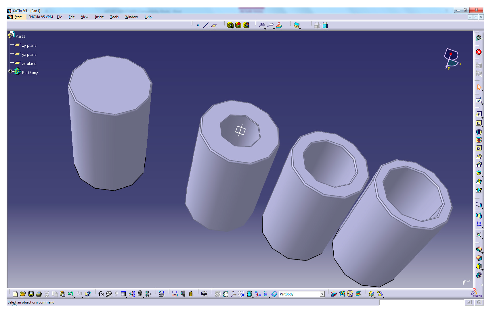
CAD/CAM software packages (Catia and Solid Works) were used to develop virtual models of hollow rollers (Figure 7). Many models have been developed based on the real situation of large solid roller bearings. The rollers’ cavities were the main element in their design. Three hollow roller 3D models with an outer diameter of 120 mm and internal diameters of 60 mm, 80 mm and 90 mm were developed.
To obtain a generalized model for the study of stresses that appear in the bearing designed in CATIA, the Geometrical Set instrument was used. Thus, it was possible to create links between the roller types in such a way that if the inner diameter of the rollers is changed, all rollers would change. The possibility of installing covers for encapsulating a lubricant inside them to improve the lubrication of the bearings was also considered (Figure 8).
Three other virtual models of hollow rollers with 2 mm, 4 mm covers were developed, the third model having, in addition to the two covers, a third inner support in the middle of the roller. Two virtual solid roller models were developed with an outer diameter of 120 mm, one cylindrical and the other logarithmic. Assembly of the roller covers is done by welding, MAG process, or hoop wrapping, on one of the rollers.
Hollow rollers designed and manufactured in this way (Figure 7) were then subjected to finite element analysis. The purpose of this analysis was to compare the contact stresses and deformations encountered during contact with the roller types proposed in this research.
3.1.2. Results of the FEA for the Hollow Rollers Bearings
The finite element analysis (FEA) was performed on a wide roller typology, taking into account the use of two specialized programs, ABAQUS and NASTRAN, and taking into account variable loads, making the study of contact stresses and deformations a safe tool.
The analysis of stresses by finite elements consists of replacing the assembly studied with a structural system made up of sub-regions, called finite elements and which, in fact, are parts of that assembly. The method uses meshing of the analyzed elements, based on which the nodes are created and their status evaluated. The computational algorithm used to make the inner-ring roller contact has the following steps [44]: it identifies from all master segments and all slave nodes those that can form potential pairs for contact, then it determines the nodal pairs that form contact, as well as the size and direction in which the contact took place, and applies to them an interaction force.
In the analysis applied to the hollow rollers, the kinematic iteration method was used, a method based on the assumption that the nodal forces are known to be uniformly distributed, and the contact forces are still to be calculated. The value of these forces is determined by successive iterations, resulting in the moment when the node’s movement speed becomes null.
Several different-sized rollers were analyzed. After applying the constraints required to run the computer program, the values of the deformations of the hollow roller bearings (Figure 9) were obtained.
The deformation analysis clearly shows that the deformations at the bottom of the bearing (the simulated and constrained part) are extremely small, at 1.16 (μm). This result shows that the maximum deformation is in the red area, and has a value of 3.13 (μm). By applying the FEA method, it was found that the specific deformations and stresses described by discrete quantities are distributed throughout the entire structure of the hollow roller bearing within the specified limits. The validation of the results obtained with the finite element analysis and the tensometric measurements leads to the conclusion that implementation of the hollow rollers in the large bearings is advantageous.
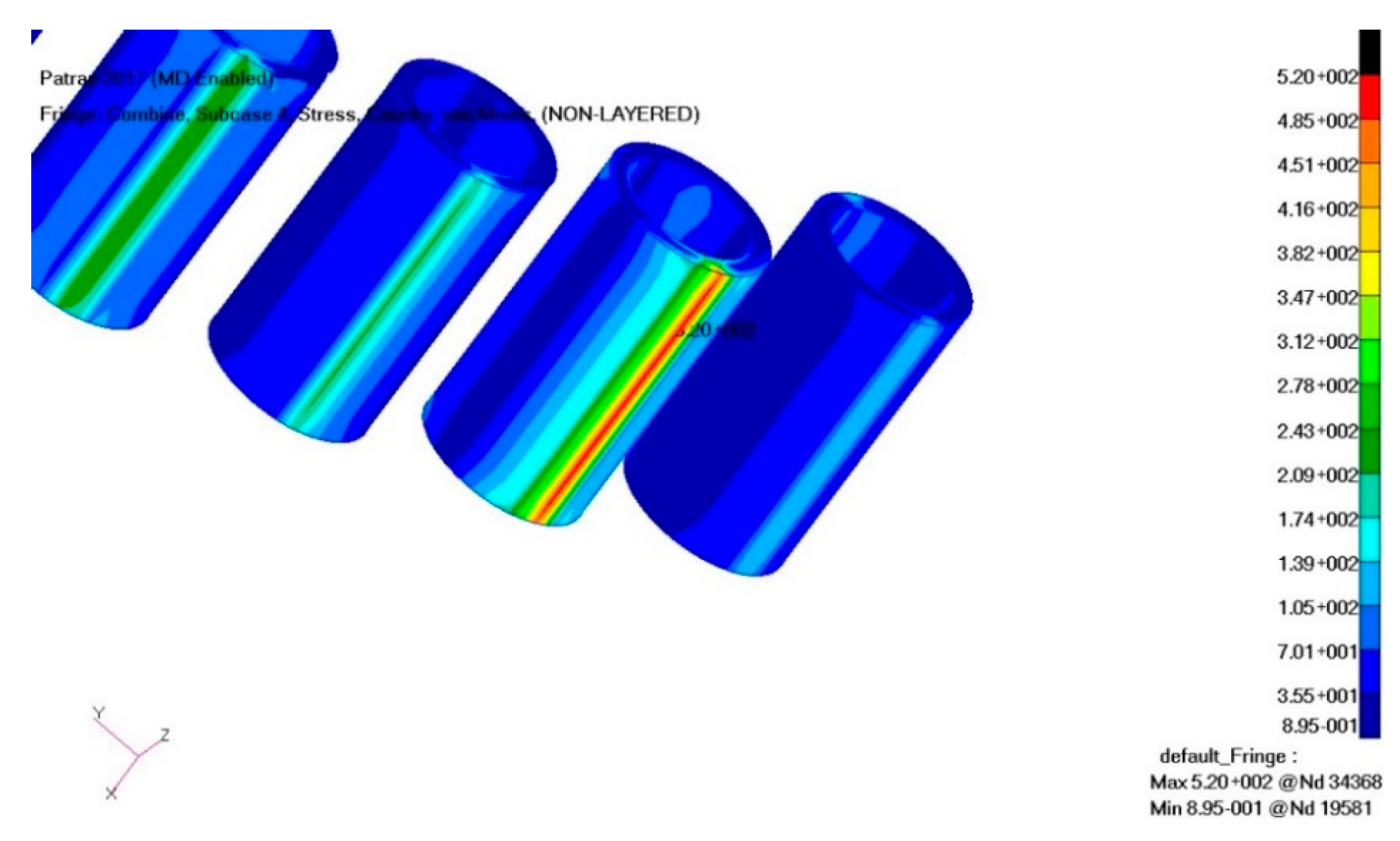
The bearing stress distribution after the application of a radial force equal to QR = 275 KN. The previously designed hollow rollers (Figure 7) are shown in Figure 10.
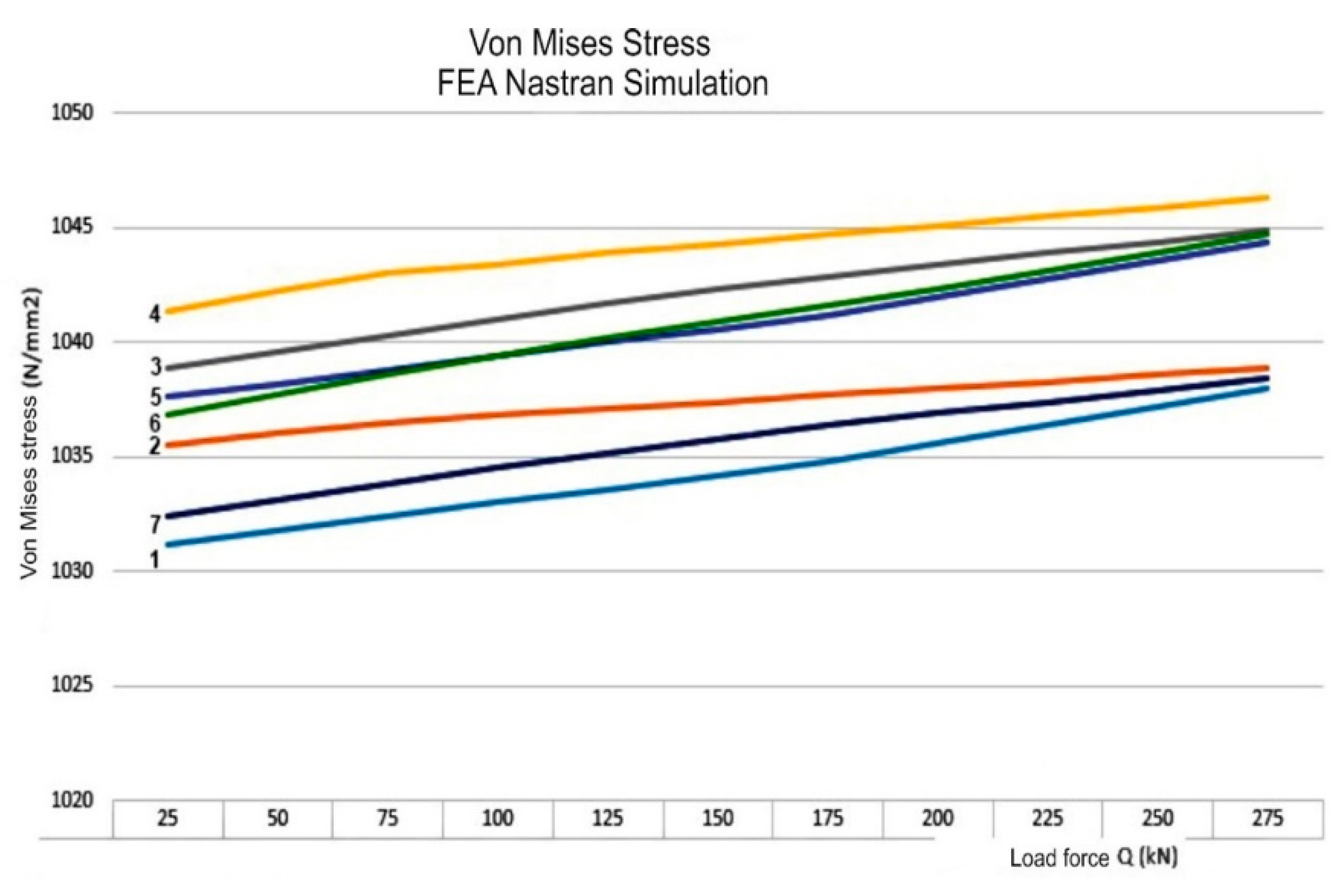
By using the Patran-Nastran software package, the Von Mises graph of stresses can be plotted by the roller type and the loading force (N/mm2); Figure 11.
The analysis was carried out on 7 roller types and sizes: 1—solid roll; 2—hollow roller (Di = 60 mm); 3—hollow roller (Di = 80 mm); 4—hollow roller (Di = 90 mm); 5—hollow roller with 2 mm covers (Di = 80 mm); 6—hollow roller with 4 mm covers (Di = 80 mm); 7—hollow roller with 2 mm caps and support in the middle (Di = 80 mm). The loading forces to which roller bearings were subjected varied between 25 (kN) and 275 (kN). By implementing the previously designed solution (Figure 9, Section 3.1.1) consisting of the mounting of caps and a bearing support in the middle of the roller, an improvement is achieved by decreasing the stresses in the roll due to the stiffening of the system. Thus, analysis of roller 7 demonstrates that stresses decrease relative to the solid roller’s stresses if the system is supported in the middle of the roller.
3.2. Dynamic Analysis of the Rotor Assembly with Hollow Roller Bearings
The elements taken into account in the dynamic analysis of the rotor assembly are the main shaft, the bearings and the mounting part in the housing [12]. Dynamic analysis is done by taking into account the rotation movement around a given axis and the forces generated on the axes by the forces and moments induced by the inertial masses, both from the blades, which take the wind force and transmit it to the main axis of the turbine, and from the reaction forces generated by the axle-bearing contact, as well as the housing bearing assembly.
Reducing inertial masses by using hollow roller bearings is the purpose of this research, and leads to an increase in the wind power system lifespan. The dynamic study of the forces acting on the main shaft and their effect—the reduction of deformations, the reduction of stresses and the reduction of temperature—are subject of this chapter.
3.2.1. Modeling Pattern
The design of the turbine shaft was executed taking into account the existing constructive variants [45]. The aim of the research is to demonstrate the advantages of introducing hollow roller bearings while preserving the current design of the other power plant components.
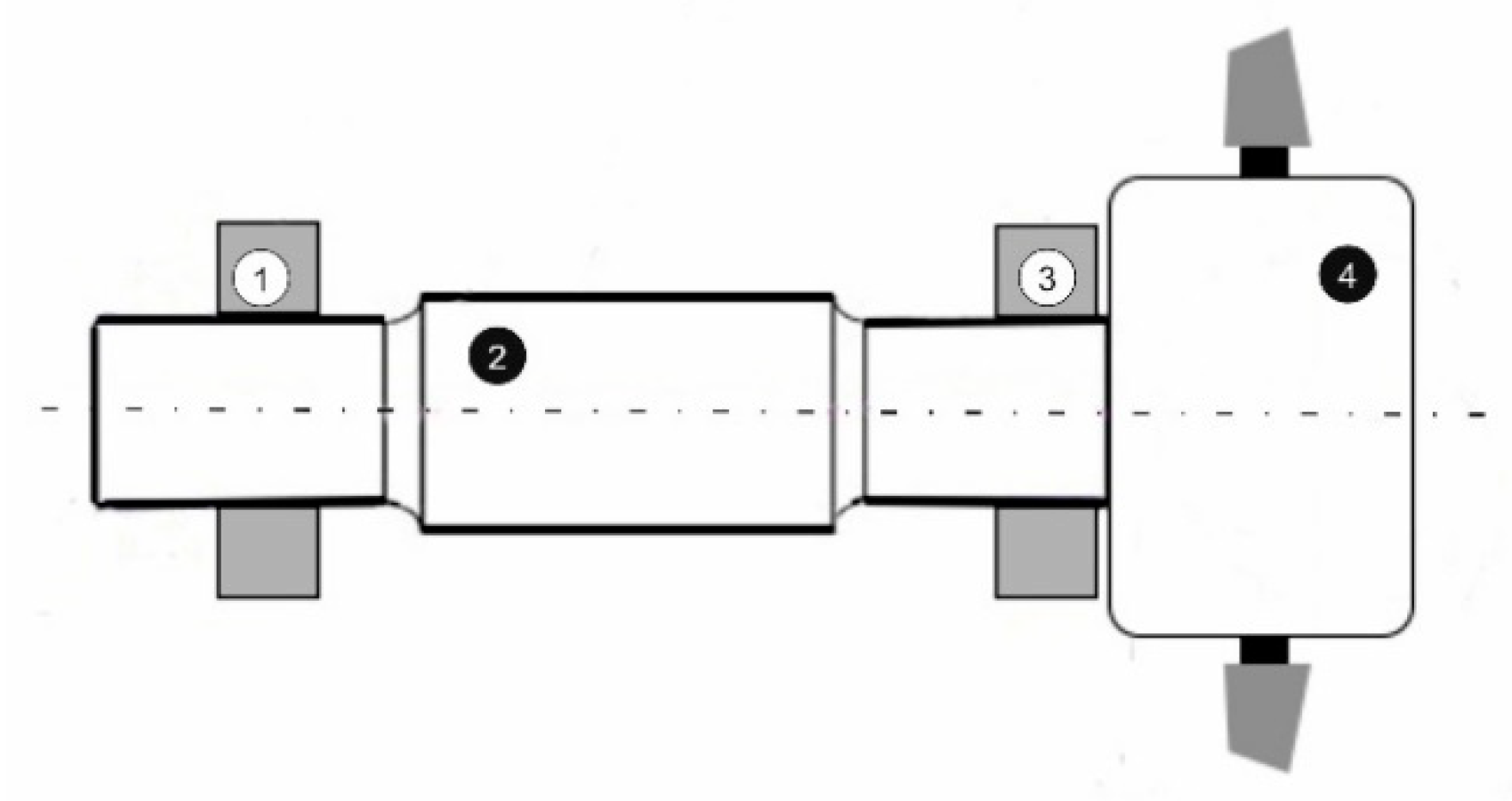
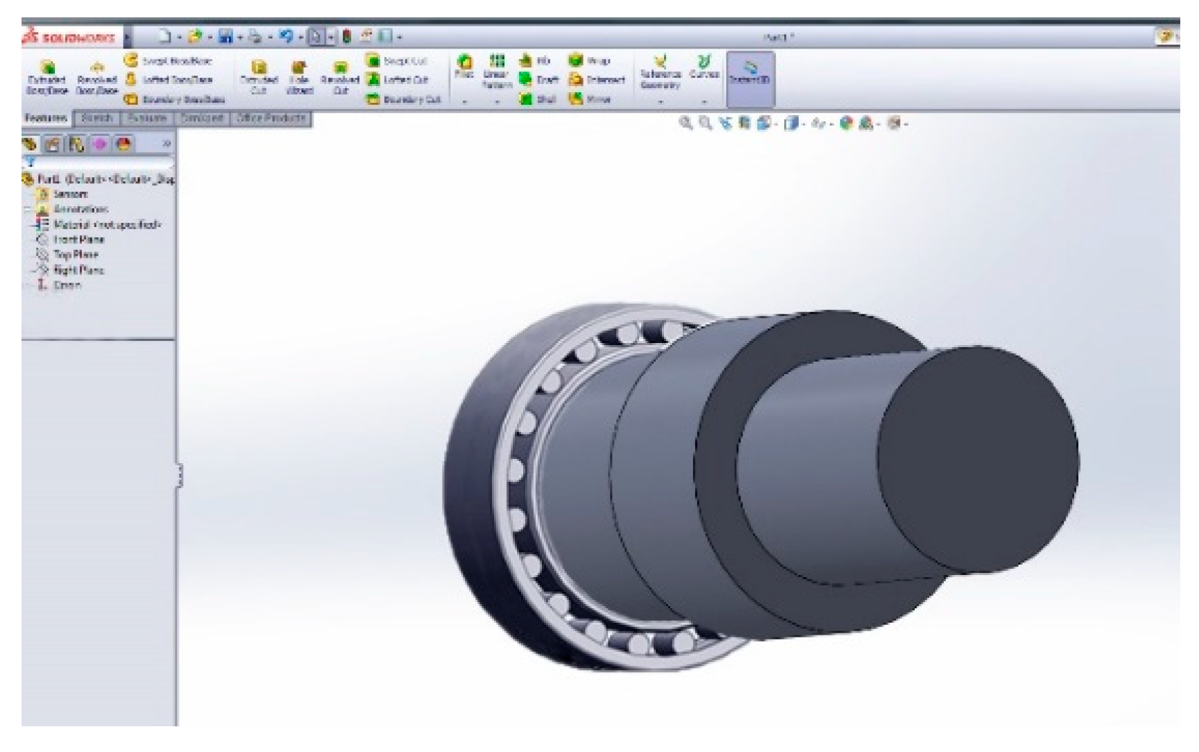
The dynamic analysis of the rotor assembly is based on the comparison between a solid roller bearing assembly and a hollow roller bearing assembly. The scheme used (Figure 12) took into account: two large bearings (pos. 1 and pos. 3), the main shaft (pos. 2) and the blade clamping system (pos. 4), which was considered to be removable in the finite element analysis. The generation of the virtual model (Figure 13) was done using Dassault Catia V5 and Solid Works.
3.2.2. Finite Element Analysis. Results and Conclusions
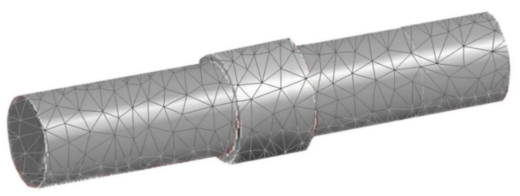
After creating the 3D model shown in Figure 13, it was subjected to finite element analysis. The model was imported into the MD Nastran program and meshed (Figure 14) by running the mesh module. The association of material properties, the creation of deformable components and the application of constraints lead to the possibility of triggering the finite element analysis operation. For the examined case study, the modeling is based on the reduction of inertial masses on a bearing with a hollow of 80 mm at a roller diameter of 120 mm.
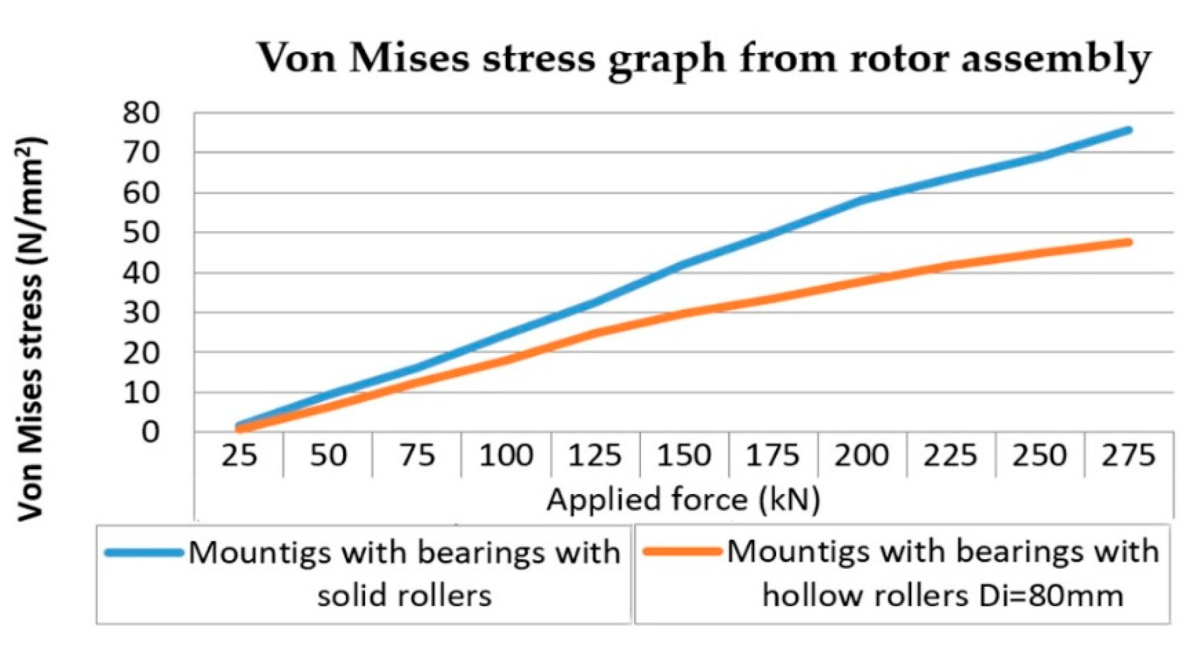
The results from the finite element analysis are shown in Figure 15. Computational elements were considered throughout the research. Variable forces (25 kN to 275 kN) were applied. The maximum pushing force Qmax = 250 kN is the pushing force of the moving blades. The reaction force in the first bearing is QReact = 275 kN, and the force in the opposite bearing is Qbearer = 150 kN. Then, the stress in the rotor assembly was measured, both for the solid roller and for the hollow roller. The Von Mises stresses on the analyzed rotor assembly are shown in Figure 15, both for solid roller bearings and for hollow roller assemblies. The results show that as the inertial masses decrease, the loading forces decrease and, with them, the effort across the system decreases. Using hollow rollers brings long-lasting benefits to all wind farms. It was observed that the maximum stress occurs in the blade section mounting area. These are the elements that set the entire assembly in motion, creating a momentum of maximum torsion. The support bearing response induces strong stresses. The decrease of inertial masses results in decreased startup resistance, forming an interesting phenomenon in the direction of decreasing stresses in the blade mounting area. In the area of the first bearing, the stress also decreases compared to the solid roller version.
The implementation of hollow rollers in large-size bearings is a clear solution that may revive the wind energy industry, which has had a slower growth over recent years. Theoretical analyses made with dedicated software tools have proven the real advantages of using hollow rollers. Increasing internal stresses in rollers leads to very small deformations that do not influence the behavior of the bearings. The three hollow rollers solution used by the company where these were tested for slippage has proven to be a viable solution that does not jeopardize the durability of the bearing, and the decrease in inertial mass causes a decrease in the effort across the system.
3.3. Automated Lubrication System Model for Large Bearings
The purpose of the applied research is to design and test a functional hollow roller model provided with an automated lubrication system for large bearings. Based on the research performed in the literature and on the Internet, the use of hollow rollers as an area for the implementation of an automated lubrication system is an entirely new approach.
There are automatic lubrication systems (SKF, Lincoln, ATS), there are large hollow roller bearings (INA Schaeffler, EDAC Technology) and there are patents related to hollow roller bearings (US 5033877, US 5071265, US 6682226), which have claims for the mounting mode or other claims different from those in this proposal. There is also the Invention Patent [13], which proposes the use of hollow rollers, containing a spongy foam impregnated with lubricant on the inside.
The development of an automated innovative lubrication system, implemented in the hollow roller, which equips the large wind turbine bearings, together with the design of a test bench for testing are among the results of this research. The implementation of such an automated system in the cylindrical hollow roller bearing has major patenting potential, and the research has an industrially applicable character.
Automated Lubrication System for Bearings. Proposed Solution
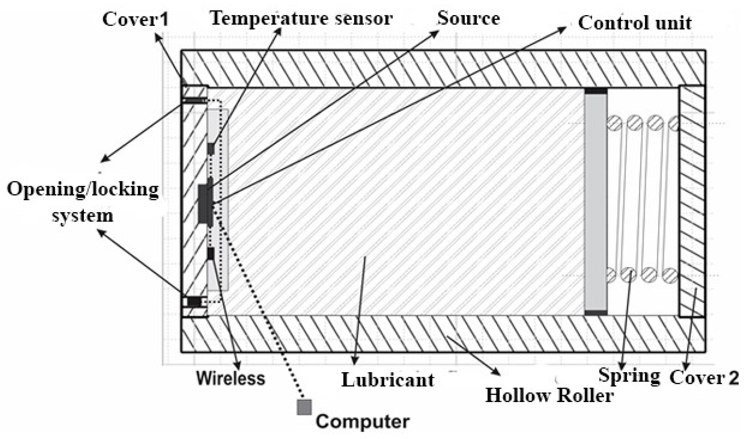
The concept of an automated lubrication system implemented in the hollow rollers that fit the large-size bearings installed in wind farms presents fundamental novelties. The innovative elements consist of the positioning of an automated lubrication system inside the hollow roller. The system would be equipped with a control unit, temperature sensors, closing/opening module for the lubrication area, wireless transmitter to the computer, power supply, and software for monitoring, command and control of the bearing’s function.
Figure 16 shows the scheme of the proposed lubrication system to be installed inside the hollow roller. Thus, the opening–closing system may be comprised of electrically actuated valves or thermal valves or magnetically actuated locking systems. The source could be a durable battery or brush collectors. The control unit could be programmable or programmed. The assembly may take place inside or outside the roller [12]. The operation of the system is managed by a control unit that unlocks the valves, leaving the lubricant to enter the runways when the sensors announce an increase in the operating temperature.
To determine all design factors, use is made of robust design by insensitivity of the chosen lubrication system to disturbing factors. With increasing temperature when the valves are open, the lubricating fluid is pushed into the tread by the piston actuated by the pressure spring. A movement of the center of gravity occurs in the roller, which can lead to additional stresses in the contact areas.
The dynamic behavior of hollow rollers provided with an automated lubrication system will be tested on a sample bench, depending on the variables acting on the system, namely:
- variables with predictable behavior that have permanent real time control (lubricant working temperature, etc.);
- variables with unpredictable behavior such as sudden burdens due to changes in the rotation speed or resonance vibration with resonant amplification.
The main problems are the identification of the optimal design solution for the discharge of the lubricant from the hollow roller and the dynamic behavior of such a roller whose center of gravity changes with the removal of the lubricant from the roller to the lubrication pathways, where previous studies have demonstrated the advantages of using hollow rollers in large-size bearings fitted in the wind power plants.
To implement the designed system, several steps will be followed:
- Develop an innovative automated lubrication system for large hollow roller bearings in wind energy assemblies.
- Design SCADA-like software to monitor, control, and lead the automated lubrication process.
- Dynamically model hollow roller bearings provided with the proposed lubrication system under variable load conditions and roller centers of gravity, which are variable over time due to lubricant removal to the tread.
- The development of a hollow roller test stand equipped with the automated lubrication system, based on previous research.
- Development of at least 3 models, based on different constructive solutions, regarding the way to introduce the lubricant from the hollow roller on the treads of the bearing.
- Elaborate the functional model of the automated lubrication system by adapting the monitoring, command and control program to the executed models.
- Test, verify and validate the functional models. Compare the experimental results with the theoretical results.
- Determine the parameters of the new computerized architecture with which the lubrication system is equipped. Optimize the system functionality.
- Assess the economic impact of the proposed solutions by making estimations of the introduction on the market of the automated lubrication for large bearings.
The research topic is broad and proposes that the future research direction will validate a new type of automated and computer-monitored bearing lubrication technology, starting from the formulation of the product concept “Hollow Roller with Built-in Bearing Lubrication”.
4. Assessment of the Economic Impact of the Proposed Solution
4.1. Estimate of the Marketing the Hollow Roller Bearings
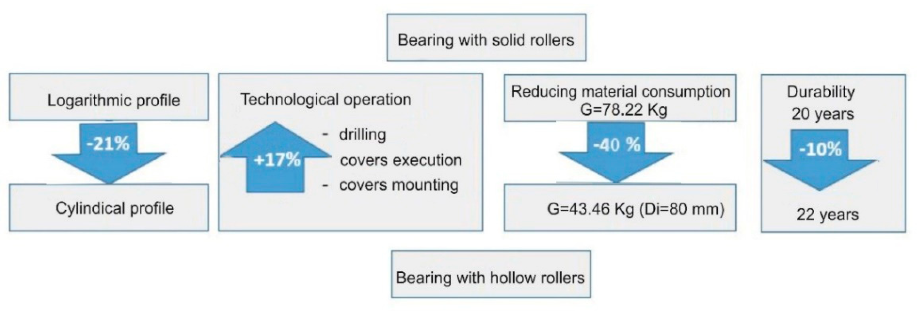
Marketing the product is closely related to the technical innovation activity. In the launch phase, sales must be fostered by smart marketing. Since the product has a high degree of novelty, and the number of competitors is small, the distribution can reach high values. Launching can be done through intense, planned distribution. The economic analysis for marketing the hollow roller bearings is based on the current product, with estimates being made for the new product. Factors influencing the analysis include changes made to rollers: additional cost changes, or cost reductions. The two categories were quantified by estimating according to values in Figure 17.
The following priorities have been considered: operational safety, reliability, environmental impact, technological change, effort to implement the solution, and benefits achieved. Priorities have been assimilated with variables within a tolerable range. In determining the benefit, two potential outlets were considered:
- the existing market, due to demand for new products;
- the market generated by the need to provide maintenance to old products.
Price discrimination in the two markets was achieved by identifying the specificities and characteristics of each market in order to maximize profit.
4.2. Estimate of the Benefit Gained by Implementing Hollow Roller Bearings in Wind Energy Assemblies
The study of energy gains was achieved with the help of dynamic control. The optimal setting of influence parameters in the power system was done using optimization techniques and the probabilistic approach. The quantification of energy savings showed significant increases with respect to the proposed objective: maximization of energy yield, and hence the cost/kW.
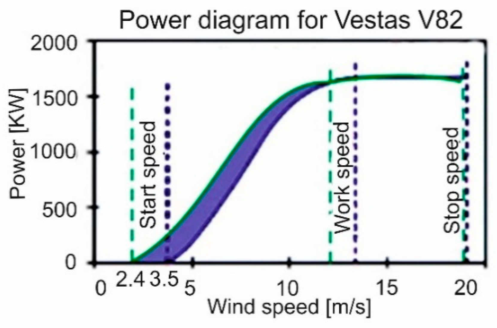
Reducing system inertia is one of the most important effects of using hollow roller bearings. Fast start, easy stop and easy control determine an increase in energy efficiency. At very low wind speeds, there is not enough torque exerted by the wind on the turbine blades to rotate them. The speed at which the turbine starts to rotate to generate energy is called the cut-in speed, and this is usually between 3 and 4 m/s. When the speed increases to values that are too high, the forces on the structure increase, generating a risk of damaging the rotor. As a result, a braking system is used to bring the rotor to a dead stop. This is called cut-off speed and is usually around 25–30 m/s. The direct relationship between wind speed and inertia leads to a decrease in the starting speed in the case of a decrease in the rotor inertial mass (Figure 18) [46].
Figure 18 shows the blue curve for the power plant equipped with solid roller bearings and green for the center with hollow roller bearings. For the Vestas V82, a reduction in speed from 3.5 m/s to 2.4 m/s was observed in the experimental observation, leading to an actual energy gain at a single start of 250 kWh. For 15 starts/month, the energy gained for a turbine is approx. 45 MWh in one year, representing 3% of the total turbine capacity.
The dynamic analysis performed by using the finite element method as well as the results of the analytical calculation leads to the conclusion that hollow cylindrical rollers can replace the more expensive and heavy logarithmic profile rollers, while increasing bearing lifespan by reducing the uneven wear of the rolling elements. Uniform stress, combined with vibration reduction and operation at a lower temperature (additional lubricant can be stored in the hollow roller) leads to an increase in energy of approx. 7% for a turbine. The expected lifespan could be around 21–22 years compared to 20 years for the traditional bearings. For a 20-roller bearing, the difference is about 700 kg, 30% lighter in weight. For a product, the energy gain for 1 year is approx. 1.5% if we approximate the weight gained with the energy accumulated. The technology energy savings for a product for one year is based on cutting the consumption of tools and requires a complex calculation. It is approximately 2% and 6%, respectively. The total energy saving is approx. 26% [14].
For a power plant of 1.65 MW/h, the energy gain is estimated to be 0.43 MW/h (1.65MW/h × 26%). The energy performance increase by implementing a hollow roller bearing in wind plants leads to increased sustainability by enhancing maintenance capabilities. Decreasing subsidies in this area make the implementation of hollow roller bearings of great interest because it leads to significant savings by reducing the maintenance cost of wind power plants through increased sustainability and energy efficiency.
5. Conclusions
The purpose of this applied research was to design and test a functional hollow roller model provided with an internal automated lubrication system for the large bearing as a sustainable solution in the field of wind energy. The optimal solution of the automated roller lubrication system was identified and the dynamic behavior of such a roller was studied. The center of gravity of the roller changes with the removal of the lubricant from the roller to the lubrication pathways. The prototype was made, and the test stand will be made as the next research step. The stand will validate or invalidate, based on actual measurements, the behavior of the lubrication system using different geometries as a result of the lubricant discharge from the rollers.
Several hollow roller patterns with different hollowness were modeled and developed, starting from the actual situation of large bearings with solid rollers. CAD/CAM programs were used, the hollow rollers being the main element in their design. To encapsulate a lubricant that improves the lubrication of the bearings, the covers were also designed and assembled. For the study of stresses by finite element analysis, the contact stresses and deformations encountered during contact with the roller types proposed in this research were compared.
Based on the dynamic analysis of the rotor assembly, a comparison was made between a solid roller bearing assembly and a hollow roller bearing assembly. By performing Von Mises analysis, the results demonstrate that with the decrease of inertial masses, the loading forces decrease and, at the same time, the effort across the system decreases.
The solution of using hollow rollers in large bearings has important effects in reducing material consumption, increasing energy yield (in the field of wind farms), increasing the durability of large bearing systems, reducing operating noise, increasing resistance to vibrations, decreasing losses through friction and lowering the working temperature. Performing studies on the behavior of these bearings under extreme vibrational conditions and variable forces would be one of the future research directions. The benefits obtained by introducing large bearings with hollow rollers into wind power assemblies are demonstrated by presenting the estimated economic calculation of product implementation. The economic impact is achieved by reducing the cost price of the whole energy package, which could be the starting point for the revitalization of the wind energy industry.
Author Contributions
All authors contributed equally to this work and all authors have read and approved the final manuscript.
Funding
This research received no external funding.
Conflicts of Interest
The authors declare no conflict of interest.
References
- Oxygen. Energy evolution on the globe. Engie Rom. 2016, 3, 03–06. [Google Scholar]
- Kumar, Y.; Ringenberg, J.; Depuru, S.S.; Devabhaktuni, V.K.; Lee, J.W.; Nikolaidis, E.; Andersen, B.; Afjeh, A. Wind energy: Trends and enabling technologies. Renew. Sust. Energ. Rev. 2016, 53, 209–224. [Google Scholar] [CrossRef]
- Blaabjerg, F.; Ke, M. Wind Energy Systems. Proc. IEEE 2017, 105, 11. [Google Scholar]
- Ponta, F.; Otero, A.; Rajan, A. The adaptive-blade concept in wind-power applications. Energy. Sustain. Dev. 2014, 22, 3–21. [Google Scholar] [CrossRef]
- Li, Y.; Caichao, Z.; Chaosheng, S.; Jianjun, T. Research and Development of the Wind Turbine Reliability. Int. J. Mech. Eng. Applic. 2018, 6, 35–45. [Google Scholar] [CrossRef]
- Torsvik, J.; Nejad, A.R.; Pedersen, E. Main bearings in large offshore wind turbines: Development trends, design and analysis requirements. Iop Conf. Ser. J. Phys. 2018. [Google Scholar] [CrossRef]
- Tazi, N.; Châtelet, E.; Bouzidi, Y. Wear Analysis of Wind Turbine Bearings. Int. J. Renew. Energy 2017, 7, 2120–2129. [Google Scholar]
- Whittle, M.; Trevelvan, J.; Tavner, P.J. Bearing currents in wind turbine generators. J. Renew. Sustain. Energy 2013, 5, 053128. [Google Scholar] [CrossRef]
- Gallego-Calderon, J.; Natarajan, A.; Dimitrov, N. Effects of bearing configuration in wind turbine gearbox reliability. Energy Procedia 2015, 80, 392–400. [Google Scholar] [CrossRef]
- Fujiwara, H.; Kawase, T. Logarithmic Profile of Rollers in Roller Bearing and Optimization of the Profile. Trans. Jpn. Soc. Mech. Eng. 2009, 18, 3022–3029. [Google Scholar]
- Barnsby, R.; Duchoski, J.; Harris, T.; Ioannides, E.; Losche, T.; Nixon, H.; Webster, M. Life ratings for modern rolling bearings. A design guide for the application of International Standard ISO 281/2. ASME, New York. TRIB. 2013, 14, 90. [Google Scholar]
- Barabaș, S.A.; Florescu, A. Analysis of bearing behavior with cylindrical rollers with variable center of gravity. Matec Web Conf. 2017, 94, 02001. [Google Scholar] [CrossRef]
- Luca, V.; Șerban, C.E.; Barabaș, S.A. Hollow roller bearing. In Patent; No. 125038; Transilvania Univesity of Brasov: Brasov, Romania, 2013. [Google Scholar]
- Barabas, B.; Florescu, A.; Barabas, S.A. Saving energy estimation for use of hollow rollers in bearings utilized in wind energy turbines. Sci. Res. Ed. Air Force Afases 2015, 2, 377–382. [Google Scholar]
- NSK Premium Technology for the Wind Industry. 2009. Available online: https://www.pkservis.com/data/web/upload/nsk/en-wind-industry-bearings.pdf (accessed on 3 July 2018).
- Bowen, W.L.; Bhateja, C.P. The Hollow Roller Bearing. ASME Trans. J. Lubr. Technol. 1980, 102, 222–228. [Google Scholar] [CrossRef]
- Pasdari, M.; Gentle, C.R. Computer Modelling of a Deep Groove Ball Bearing with Hollow Balls. WEAR 1986, 111, 101–114. [Google Scholar] [CrossRef]
- Darji, P.H.; Vakharia, D.P. Development of Graphical Solution to Determine Optimum Hollowness of Hollow Cylindrical Roller Bearing Using Elastic Finite Element Analysis. In Finite Element Analysis-Applications in Mechanical Engineering; Chapter 11; InTech: Vienna, Austria, 2012. [Google Scholar] [CrossRef] [Green Version]
- Abu-Jadayil, W.M. Relative fatigue life estimation of cylindrical hollow rollers in general pure rolling contact. Tribotest 2008, 14, 27–42. [Google Scholar] [CrossRef]
- SKF Evolution. 2011. Available online: http://evolution.skf.com/centralized-lubrication-system-for-wind-turbines-offers-improved-efficiency/ (accessed on 27 August 2018).
- Martin, R.; Lazakis, I.; Barbouchi, S.; Johanning, L. Sensitivity analysis of offshore wind farm operation and maintenance cost and availability. Renew. Energy 2016, 85, 1226–1236. [Google Scholar] [CrossRef] [Green Version]
- European Commission. COM. Renew. Energy Progress Report; European Commission: Brussels, Belgium, 2017; Available online: https://ec.europa.eu/commission/sites/beta-political/files/report-renewable-energy_en.pdf (accessed on 7 October 2018).
- GWEC (Global Wind Energy Council). Glob. Wind Rep. 2017. Available online: www.gwec.net (accessed on 10 October 2018).
- International Energy Agency. IEA. 2017. Available online: https://www.iea.org/ (accessed on 9 October 2018).
- WEEA Report. 2018. Available online: https://wwindea.org/ (accessed on 9 October 2018).
- Ziegler, L.; Gonzalez, E.; Rubert, T.; Smolka, U.; Malero, J. Lifetime extension of onshore wind turbines: A review covering Germany, Spain, Denmark, and the UK. Renew. Sust. Energ. Rev. 2018, 82, 1261–1271. [Google Scholar] [CrossRef] [Green Version]
- PowerWeb. Renew. Energy. 2018. Available online: http://www.fi-powerweb.com/Renewable-Energy.html (accessed on 2 September 2018).
- European Comision. Clean Energy for All Europeans—Unlocking Europe’s Growth Potential. 2016. Available online: http://europa.eu/rapid/press-release_IP-16-4009_en.htm (accessed on 7 October 2018).
- Calanter, P. The role of renewable energy in action to combat climate change in the European Union. EUROINFO 2018, 2, 19–31. [Google Scholar]
- Government of Romania; Programul Natiunilor Unite pentru Dezvoltare. Nat. Strategy for Sustain. Dev. Romania. Horizon 2013-2020-2030; Government of Romania: Romania, Bucharest, 2008.
- Government of Romania. Energy Strategy of Romania 2016–2030, with the Perspective of 2050; Government of Romania: Bucharest, Romania, 2016.
- Eurostat. 2018. Available online: http://ec.europa.eu/eurostat/statisticsexplained/index.php?title=Renewable_energy_statistics/ro (accessed on 15 August 2018).
- RWEA (Romanian Wind Eolian Association). 2017. Available online: http://rwea.ro (accessed on 7 June 2018).
- ANRE. 2017. Available online: https://www.anre.ro/ro/energie-electrica/rapoarte/rapoarte-indicatori-performanta (accessed on 8 June 2018).
- SKF. Rolling bearings; SKF Group: Gothenburg, Sweden, 2018. [Google Scholar]
- TIMKEN. Engineering Lubrication and Seals; The Timken Company: North Canton, OH, USA, 2009; pp. 146–162. [Google Scholar]
- INA Schaeffler. Tapered Roller Bearing Catalogue; Schaeffler Technologies AG & Co.: Schweinfurt, Germany, 2017. [Google Scholar]
- FAG; OEM; Handel AG. The Design of Rolling Bearing Mountings; Publ. No. WL 00 200/6 EA; Schaeffler Technologies AG & Co.: Schweinfurt, Germany, 2012. [Google Scholar]
- Wind Measurement International. WMI. Available online: http://www.windmeasurementinternational.com/ (accessed on 11 October 2018).
- Turi, M.B.; Marks, C.S. Analysis Helps Wind Turbine Designers Find Their Bearings; Timken, Co.: Canton, OH, USA, 2010. [Google Scholar]
- Burton, T. Wind Energy Handbook, 2nd ed.; Wiley: Chichester, UK; New York, NY, USA, 2011. [Google Scholar]
- Lyatkher, V.M. Wind Power: Turbine Design, Selection, and Optimization; Scrivener Publishing, Wiley: New Jersey, NJ, USA, 2014. [Google Scholar]
- Song, Y.D.; Dhinakaran, B.; Bao, X.Y. Industrial Aerodynamics. J. Wind Eng. 2000, 85, 293–308. [Google Scholar]
- Ebert, F.J. Fundamentals of Design and Technology of Rolling Element Bearing. Chin. J. Aeronautics 2014, 23, 123–136. [Google Scholar] [CrossRef]
- Smith, E.H. Mechanical Engineer’s Reference Book; Linacre House: Jordan Hill, Oxford, UK, 2000; pp. 9–56. ISBN 0-7506-4218-1. [Google Scholar]
- Kakuta, K. High Speed Rolling Bearings for Gas Turbines. Jpn. J. Tribol. 1990, 35, 877–889. [Google Scholar]
Figure 1.
Total installed capacity 2013–2017 (Source: WWEA).

Figure 2.
Growth rate of total installed capacities (Source: WWEA).

Figure 3.
Global cumulative wind capacity at the end of 2017 (Source: GWEC).

Figure 4.
Share of wind in total gross electricity generation in the EU Member States, 2016 (Source: Eurostat 2017).
Figure 4.
Share of wind in total gross electricity generation in the EU Member States, 2016 (Source: Eurostat 2017).

Figure 5.
Rotary systems: rotor, blade, pivot, provided with large bearings.

Figure 6.
Logical scheme for choosing the optimal construction solution.

Figure 7.
Cylindrical hollow roller models proposed for implementation.

Figure 8.
Hollow roller bearing with lubrication covers and extra support in the middle.

Figure 9.
Deformations of the hollow cylindrical roller bearing (mm).

Figure 10.
Cauchy and Von Mises stresses occurring in hollow rollers (MPa).

Figure 11.
Von Mises stress graph according to roller type and load force (N/mm2).

Figure 12.
Study scheme of the main shaft.

Figure 13.
Main shaft and bearing.

Figure 14.
Meshing of the main shaft in MD Nastran software.

Figure 15.
Von Mises stress graph from rotor assembly.

Figure 16.
Diagram of the proposed automated lubrication system.

Figure 17.
Diagram of the economic impact assessment of marketing hollow roller bearings.

Figure 18.
Vestas V82 turbine power diagram.


Table 1.
Estimated global wind power (Source: GWEC 2017).
| Global Total | |||||||
|---|---|---|---|---|---|---|---|
| Total Capacity in MW | 2013 | 2014 | 2015 | 2020 | 2030 | 2040 | 2050 |
| New Policies Scenario | 318,354 | 369,596 | 432,656 | 639,478 | 1.259,974 | 2.052,528 | 2.869,611 |
| 450 Scenario | 318,354 | 369,596 | 432,656 | 658,009 | 1.454,395 | 2.458,757 | 3.545,595 |
| Moderate Scenario | 318,354 | 369,596 | 432,656 | 797,028 | 1.675,624 | 2.767,351 | 3.983,995 |
| Advanced Scenario | 318,354 | 369,596 | 432,656 | 878,446 | 2.110,161 | 3.720,919 | 5.805,882 |
© 2019 by the authors. Licensee MDPI, Basel, Switzerland. This article is an open access article distributed under the terms and conditions of the Creative Commons Attribution (CC BY) license (http://creativecommons.org/licenses/by/4.0/).
Share and Cite
MDPI and ACS Style
Florescu, A.; Barabas, S.; Dobrescu, T. Research on Increasing the Performance of Wind Power Plants for Sustainable Development. Sustainability 2019, 11, 1266. https://0-doi-org.brum.beds.ac.uk/10.3390/su11051266
AMA Style
Florescu A, Barabas S, Dobrescu T. Research on Increasing the Performance of Wind Power Plants for Sustainable Development. Sustainability. 2019; 11(5):1266. https://0-doi-org.brum.beds.ac.uk/10.3390/su11051266
Chicago/Turabian StyleFlorescu, Adriana, Sorin Barabas, and Tiberiu Dobrescu. 2019. "Research on Increasing the Performance of Wind Power Plants for Sustainable Development" Sustainability 11, no. 5: 1266. https://0-doi-org.brum.beds.ac.uk/10.3390/su11051266
Note that from the first issue of 2016, this journal uses article numbers instead of page numbers. See further details here.