Research on Frequency Fuzzy Adaptive Additional Inertial Control Strategy for D-PMSG Wind Turbine

1
Science & Technology College, North China Electric Power University, Baoding 071003, China
2
College of Control and Computer Engineering, North China Electric Power University, Baoding 071003, China
*
Author to whom correspondence should be addressed.
Sustainability 2019, 11(15), 4241; https://0-doi-org.brum.beds.ac.uk/10.3390/su11154241
Submission received: 30 May 2019
/
Revised: 15 July 2019
/
Accepted: 2 August 2019
/
Published: 6 August 2019
(This article belongs to the Special Issue Applications, Integration and Trends of Renewable Energy Technologies)
Abstract
:The traditional additional inertial control (T-AIC) strategy can provide frequency support for the directly-driven wind turbine with a permanent magnet synchronous generator (D-PMSG). However, due to the fixed control coefficients, the frequency modulation effect is poor under load and wind speed disturbances. In order to improve the frequency transient response of D-PMSG, a fuzzy adaptive additional inertial control strategy (FA-AIC) is proposed in this paper. A simplified D-PMSG model is established for the complexity and low calculation speed. A single-machine grid-connected system composed of a D-PMSG and an equivalent synchronous generator set (ESGS) is taken as the background and analysis of the principle of T-AIC. The proportional and derivative coefficient initial values in T-AIC are tuned by simulating the static characteristics and inertial response characteristics of the conventional synchronous generator set, and fuzzy control technology is introduced to adjust the proportional and derivative coefficients adaptively based on the frequency deviation and the frequency deviation change rate under load or wind speed disturbances. The simulation verification indicates that T-AIC, kinetic energy (KE)-based gain-AIC and FA-AIC all can utilize the D-PMSG additional inertial response to provide frequency support for grid-connected systems. Compared with T-AIC and KE-based gain-AIC, the proposed FA-AIC can not only provide more effective frequency support during load disturbances, but also suppress the frequency fluctuation caused by the wind speed variation and displays a better dynamic frequency regulation effect.
1. Introduction
As the main steam of renewable energy, wind power has become the fastest-growing new energy and will be a major source of electrical power in the near future [1,2,3]. Recently, the widely used variable-speed wind turbine generators (WTGs) can be classified as two types: The doubly-fed induction generator (DFIG); and the directly-driven wind turbine with the permanent magnet synchronous generator (D-PMSG). The D-PMSG has become the dominant model in the wind power market due to the advantages of high efficiency, high reliability, competitive costs and wide operating ranges [4,5,6]. At present, the D-PMSG usually operates in maximum power point tracking (MPPT) control mode for maximum wind energy through the full power converter. However, owing to the rotor speed of PMSG and the decoupling of the system frequency in this control mode, the active power can only be adjusted according to the rotor speed and wind speed without responding to the system frequency deviation. Therefore, D-PMSG cannot provide additional active power to participate in grid frequency regulation. The large-scale wind power integration inevitably leads to the lower system inertia and larger system frequency fluctuations during load disturbances [7,8,9]. Therefore, it is of great theoretical and practical significance to study the frequency control strategy and improve the ability of actively participating in grid frequency regulation for D-PMSG.
Domestic and foreign scholars have undertaken considerable research which has been aimed at enabling wind turbine generators to provide similar power support as traditional synchronous generators and to participate in system frequency regulation actively during frequency fluctuations. In general, the D-PMSG wind turbine frequency control strategy can be divided into two parts: The droop deloading control; and additional inertia control [10,11,12]. The droop deloading control reduces the capture power of the D-PMSG wind turbine in advance and releases the reserved standby power to participate in system frequency regulation. It can take a considerable amount of time for the adjusting process and is at the expense of wind energy utilization and the operational economy [13,14]. The paper [15] offered a frequency response control method based on rotor kinetic energy in wind turbines. This method introduces auxiliary control loops related to the system frequency deviation and the frequency deviation change rate on the basis of the maximum power point tracking (MPPT) control to simulate the inertia response characteristics of the traditional synchronous generator and to improve the frequency response characteristics. When the system frequency alters, the D-PMSG can release or store the rotor kinetic energy to provide short-term frequency support and to participate in frequency regulation. As the converter can regulate the active power quickly, the D-PMSG wind turbine generators can virtualize greater virtual inertia than their inherent inertia. The so-called additional inertial control (AIC) method is therefore derived. In [16,17], the frequency deviation and the frequency deviation change rates are introduced to realize the AIC, the modules are added to the wind turbine for the purpose of simulating the inertial response of the synchronous generators to achieve fast active power regulation and to respond to system frequency deviation. In [18], an additional active power is provided by the rotor kinetic energy stored in wind turbine which is determined by the frequency deviation and the frequency deviation change rate. The AIC control scheme is a zero power consumption process and has been widely applied in improving the transient stability of the system frequency. Thus, this paper only focuses on the AIC method that aims to improve the frequency transient response and to ensure the stable operation for the D-PMSG.
However, in a traditional AIC (T-AIC) strategy, the proportional and derivative coefficients related to the system frequency deviation and frequency deviation change rate in the auxiliary control loops are usually predetermined to fixed values [15,16,17,18]. This means that under wind speed or load disturbances, a large coefficient can improve the D-PMSG frequency minimum value, but it might result in a minimum speed limit and participate in frequency regulation excessively, which is determined by the capacity of D-PMSG converter [19]. On the contrary, a small coefficient could ensure the stable operation of the D-PMSG, however, it supplies limited frequency support and cannot fully utilize the frequency regulation capability. Therefore, it is not conducive to improve the transient frequency regulation performance of the D-PMSG.
At present, the variable coefficient strategies for the AIC have been discussed. In [20], it was concluded that the different control coefficients should be adopted for units under different wind speeds in order to achieve a better frequency modulation effect. The paper [21], introduced the additional inertia time constant to adjust the proportional and derivative coefficients adaptively, but the calculation of the additional inertia time constant is complicated. In [22], the control coefficients were tuned online according to the available power of the frequency regulation in different wind speed zones, but only the proportional coefficient was tuned and the derivative coefficient was not considered. For the isolated islanding wind/photovoltaic/diesel micro-grid, the proportional and derivative coefficients of the double-fed induction generators in different wind speed zones were determined through the simulation trial method in [23], but the method has certain empirical limitations. The paper [24], introduced the rotor kinetic energy evaluation factor and the converter capacity limit factor to adjust the proportional and derivative coefficients for the D-PMSG wind turbine. In [25], a set of control coefficients were obtained through the enumeration search method according to a proposed criterion. However, it is difficult to find the optimal coefficients and the corresponding frequency response performance is comprehensively determined by a defined criterion. The paper [26], proposed a released kinetic energy-based inertial control scheme for a DFIG, and the proportional and derivative coefficients were adjusted according to the rotor speed owing to a higher rotor speed which means releasing more kinetic energy. However, the two coefficients are altered based on the rotor speed in the initial stage of the frequency modulation and remain constant during the frequency modulation process. In addition, the above-mentioned variable coefficient methods focus on improving the frequency modulation capability of wind turbines in different wind speeds by altering the coefficients, and adjusting the coefficients is based on the wind turbine initial state in the early stage of the frequency modulation. However, during the frequency modulation process, the wind speed and the load could vary randomly. Therefore, the above-mentioned variable coefficient methods cannot ensure a better frequency regulating effect for the wind turbine during the frequency modulation process.
Thus far, the robust adaptive control techniques have been developed to deal with changes in system parameters. The applications of neural networks, genetic algorithms, optimal control and model predictive control (MPC) for the frequency control have been reported in [27,28,29,30]. Compared with the abovementioned methods, the fuzzy logic control displays better performance, such that there is no need for accurate mathematical models, robustness against load disturbances and parameter uncertainty. The fuzzy logic methodology is a practical control method which has been widely applied in research on frequency control with and without nonlinearities [31]. The paper [32], proposed a parameter adaptive PID-Type fuzzy controller in a wind-diesel power system to improve the frequency performance. The paper [33], applied the artificial bee colony algorithm based on the fuzzy-logic controller to maintain the system frequency in a high wind penetrated power system within a normal operating band. In [34], a novel fuzzy theory-based coordinated control strategy was proposed for improving the short-term frequency response capability of a DFIG-energy storage (ES) system. Since the T-AIC model for the D-PMSG wind turbine is nonlinear and the relations between the proportional/derivative coefficients and the frequency deviation under wind speed or load disturbances are complicated, the fuzzy logic control method is chosen as the adaptive controller in this paper.
A fuzzy adaptive additional inertial control strategy (FA-AIC) is proposed in this paper to improve the T-AIC theme for the D-PMSG and ameliorate the frequency response characteristic of the D-PMSG wind turbine. The proportional and derivative coefficients are adjusted adaptively based on the system frequency deviation and the frequency deviation change rate under load or wind speed disturbances. The proposed FA-AIC can suppress the system frequency deviation effectively and display better dynamic frequency modulation capability.
The rest of this paper is arranged as follows. The simplified model of D-PMSG is introduced in Section 2. The traditional additional inertial control principle is analyzed in Section 3. Then, the initial values tuning of the proportional and derivative coefficients are presented in Section 4. A fuzzy adaptive additional inertial control strategy is designed in Section 5. The effectiveness of the proposed frequency control strategy is assessed by means of MATLAB/Simulink platform in Section 6. Finally, some conclusions are presented in Section 7.
2. Simplified Model of D-PMSG Wind Turbine
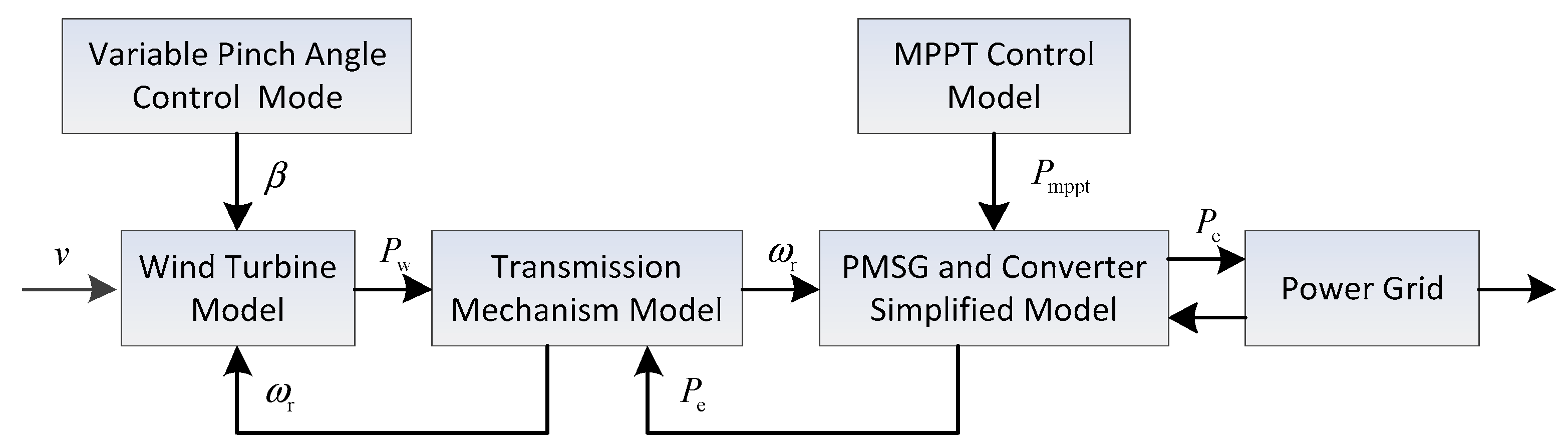
The simplified model of the D-PMSG wind turbine is mainly comprised of the wind turbine model, the transmission mechanism model, the control system model, the PMSG and the converter model, as shown in Figure 1.
2.1. Wind Turbine Model
According to the aerodynamic principle, the actual output of mechanical power of the wind turbine can be stated as (1) [35].
where ρ is the air density (kg/m3), is the power coefficient and the theoretical optimal value is 0.593, is the tip speed ratio, is the blade pitch angle (°), is the wind turbine blade radius (m) and is the wind turbine blade mechanical speed ().
2.2. Transmission Mechanism Model
Furthermore, ignoring the flexible shaft and the mechanical loss between the rotor of the wind turbine and the generator, a single mass model is equivalent to simulate the transmission device [36,37]:
where is the wind turbine speed, is the inertia time constant of the equivalent single mass model, is the wind turbine mechanical torque, is the electromagnetic torque.
2.3. Control System Model
According to different wind speeds, the D-PMSG control system consists of two control modules—the MPPT control under the condition of the wind speed is below the rated wind speed; and the variable pitch control when the wind speed is higher than the rated wind speed.
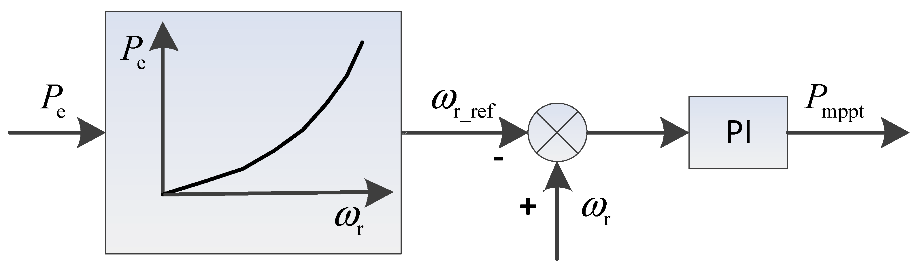
2.3.1. MPPT Control
2.3.2. Variable Pitch Control
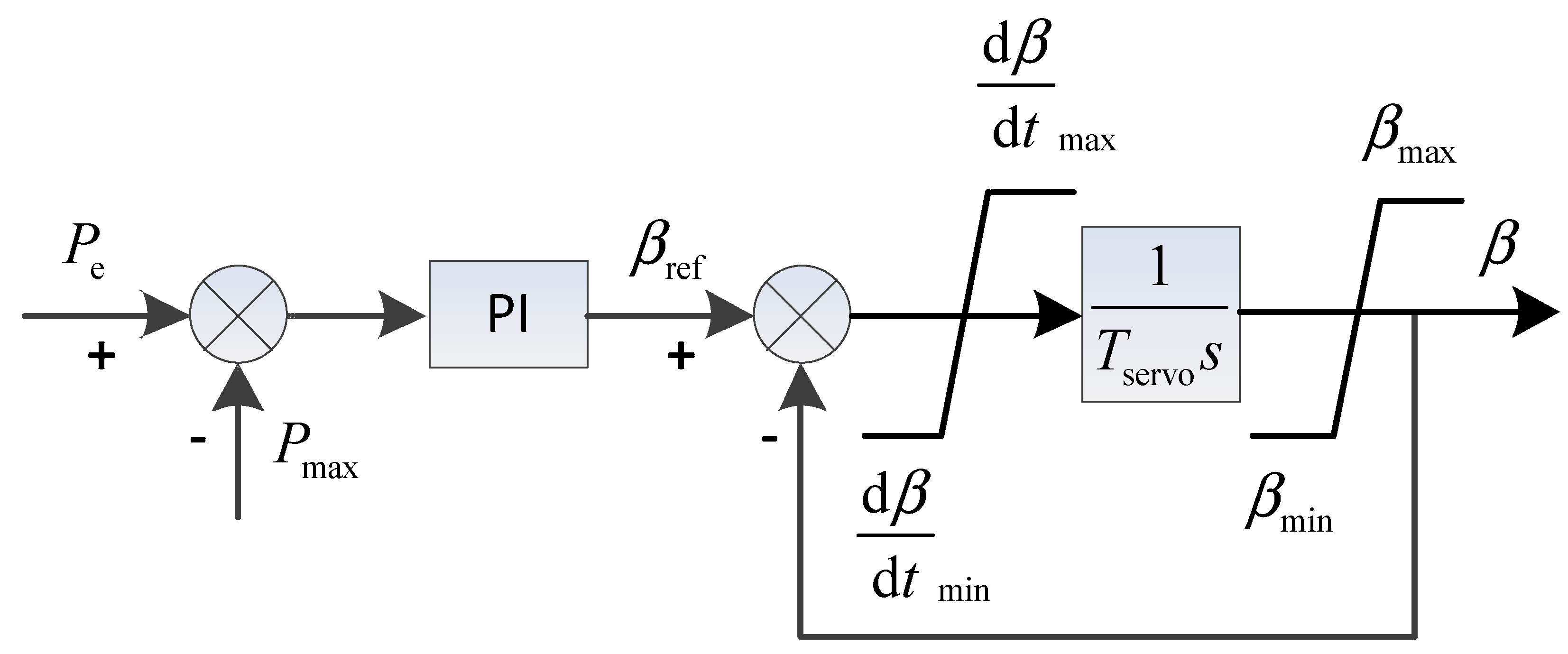
The blade pitch angle is adjusted through the pitch angle control section to regulate the active power output. Figure 3 indicates the variable pitch control structure diagram. The pitch angle remains when the wind speed is lower than the rated value. On the contrary, the pitch angle is adjusted to maintain the rated output power.
The deviation between the actual active power and the D-PMSG maximum power is used to perform the PI operation and calculate the pitch angle reference value [38]. is the servo time constant, and are the pitch angle amplitude limits, and are the pitch angle speed limits, β is the output pinch angle.
2.4. Generator/Converter Model
The power system frequency response characteristics are an electromechanical transient process and are mainly affected by the power-frequency characteristics of the unit. In this paper, the PMSG and converter are equivalent to an inertia link merely considering the active output characteristics of the unit [15,39]. The simplified mathematical model of the generator and the converter can be stated as follows:
where is the equivalent time constant of the PMSG and the converter.
3. Principle of Traditional Additional Inertia Control
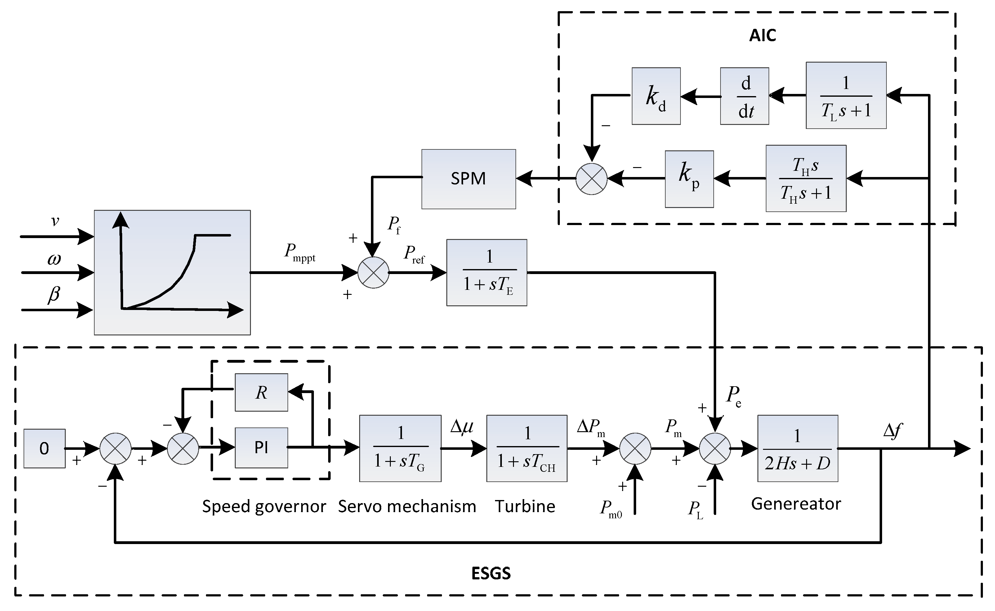
The power system inertia reflects the ability of the system to prevent frequency variation, and allows the generator to adjust the generating power and build a new power balance when the system frequency fluctuates. However, in the MPPT control mode, the D-PMSG can only regulate the active power according to the wind turbine rotor speed and cannot provide inertial support. A frequency control module can be added to the D-PMSG wind turbine power control so as to simulate the inertia response characteristics of the traditional synchronous generator. The principle of additional inertia control for the grid-connected D-PMSG is shown in Figure 4.
The equivalent synchronous generator set (ESGS) is a simulation of the grid in this paper, which is composed of a speed control system, a turbine and a synchronous generator, where the speed control system consists of a governor and a servo mechanism [40]. An auxiliary power related to the proportional and derivative terms of the system frequency deviation is introduced to simulate the inertia response characteristics of the traditional synchronous generator. Thus, the D-PMSG wind turbine can adjust the output power when the system frequency fluctuates—that is the traditional additional inertia control (T-AIC). As is shown in Figure 4, the principle of T-AIC is stated as:
where is the auxiliary power of AIC; denotes the frequency deviation, , and are measured values and the reference value of the system frequency, respectively; and are the proportional and derivative coefficients, respectively, , in practical application. A high and a low pass filter are also added to the AIC module respectively. The speed protection module (SPM) ensures the wind turbine exits the AIC when the rotor speed is lower than 0.67 and prevents the speed from being too low and causing cutting machine accidents [41].
In the T-AIC mode, the output power of the D-PMSG consists of two parts: The active power of MPPT control; and the auxiliary power of the AIC. It is stated as:
Obviously, the D-PMSG output power would increase when the system frequency drops, which would make the rotor speed decrease and release rotational kinetic energy to mitigate the frequency falling.
However, ignoring the inertia of the converter, , therefore, the frequency response of the grid-connected system in the MPPT control mode is expressed as:
After the AIC is introduced, the grid-connected system frequency turns to follow:
where is the inertia time constant of the synchronous generator, is the damping coefficient; is the output power of the synchronous generator; is the wind power output and is the load power. It can be seen that the introduction of the AIC makes the inertia and damping constant of the grid-connected system increase by and respectively, which improves the system frequency response characteristic from the aspects of inertia and damping.
4. Initial Values Tuning for Proportional and Derivative Coefficient
The T-AIC is simple in principle and clear in physical meaning, but it has difficulty in adjusting the parameters / and has poor adaptability under wind speed and load disturbances. Therefore, this paper proposes a fuzzy adaptive additional inertia control (FA-AIC) strategy based on the T-AIC, with two initial values tuning for proportional and derivative coefficient.
The AIC of the D-PMSG is a simulation of the static characteristics and inertial response characteristics of the conventional synchronous generator set. In order to make the D-PMSG wind turbine unit have similar frequency modulation characteristics and inertial response characteristics with the ESGS, this paper tunes the initial values of the proportional and derivative coefficient and firstly accords to the parameters of the ESGS.
4.1. Proportional Coefficient Initial Value Tuning
When the system frequency fluctuates, the additional power of the static characteristic for the synchronous generator set is stated as (pu):
where and are the static frequency characteristic coefficient and the static frequency difference coefficient of the ESGS, respectively.
When the system frequency changes, the additional power of the D-PMSG wind turbine under the droop control is expressed as:
According to the equivalent relation, combining (8) and (9), (10) can be derived as follow:
That is, the proportional coefficient initial value can be derived based on the static frequency difference coefficient of the ESGS.
4.2. Derivative Coefficient Initial Value Tuning
The inertia time constant of ESGS is expressed as:
where , and are the moment inertia, rated speed and rated power of the ESGS respectively.
The kinetic energy stored by the ESGS is stated as:
The speed also changes along with the system frequency deviation, and the corresponding additional power of synchronous generator set is:
Combining (11) and (13), (14) can be derived as:
In the normal operation, the grid-connected system frequency has less fluctuation and , so (14) can be simplified as:
When the system frequency changes, the additional power of the D-PMSG wind turbine due to the change of rotor kinetic energy is expressed as:
According to the equivalent relation, combining (15) and (16), (17) can be derived as follows:
The D-PMSG inertia time constant is stated as:
where , and are the moment inertia, rated speed and rated power of the D-PMSG wind turbine, respectively.
According to the equivalent relation, the D-PMSG and the ESGS have the same time constant, . Therefore, the D-PMSG inertia time constant is also expressed as:
That is, the derivative coefficient initial value can be obtained utilizing the moment inertia , rated speed and rated power of the D-PMSG wind turbine itself.
5. Fuzzy Adaptive Controller for Proportional and Derivative Coefficients Adjusting
The fixed proportional and derivative coefficients and in the T-AIC would cause the D-PMSG to participate in frequency modulation excessively or to not fully utilize the frequency modulation capability under the load or wind speed disturbances. It is not conducive to improve the overall frequency modulation performance for the units [12]. In addition, the safe speed range of the MW unit is 0.67~1.33 pu [20] due to the limitation of physical devices, however, the unit speed changes when participating in frequency modulation. The larger proportional or derivative coefficient results in releasing excessive power and causes the unit speed to exceed the safe range. In order to improve the frequency response characteristic of the D-PMSG wind turbines and solve the problem of the fixed coefficients in the T-AIC (which cannot implement frequency modulation under wind speed or load disturbances), a fuzzy adaptive controller for the proportional and derivative coefficients adjusting is proposed in this paper.
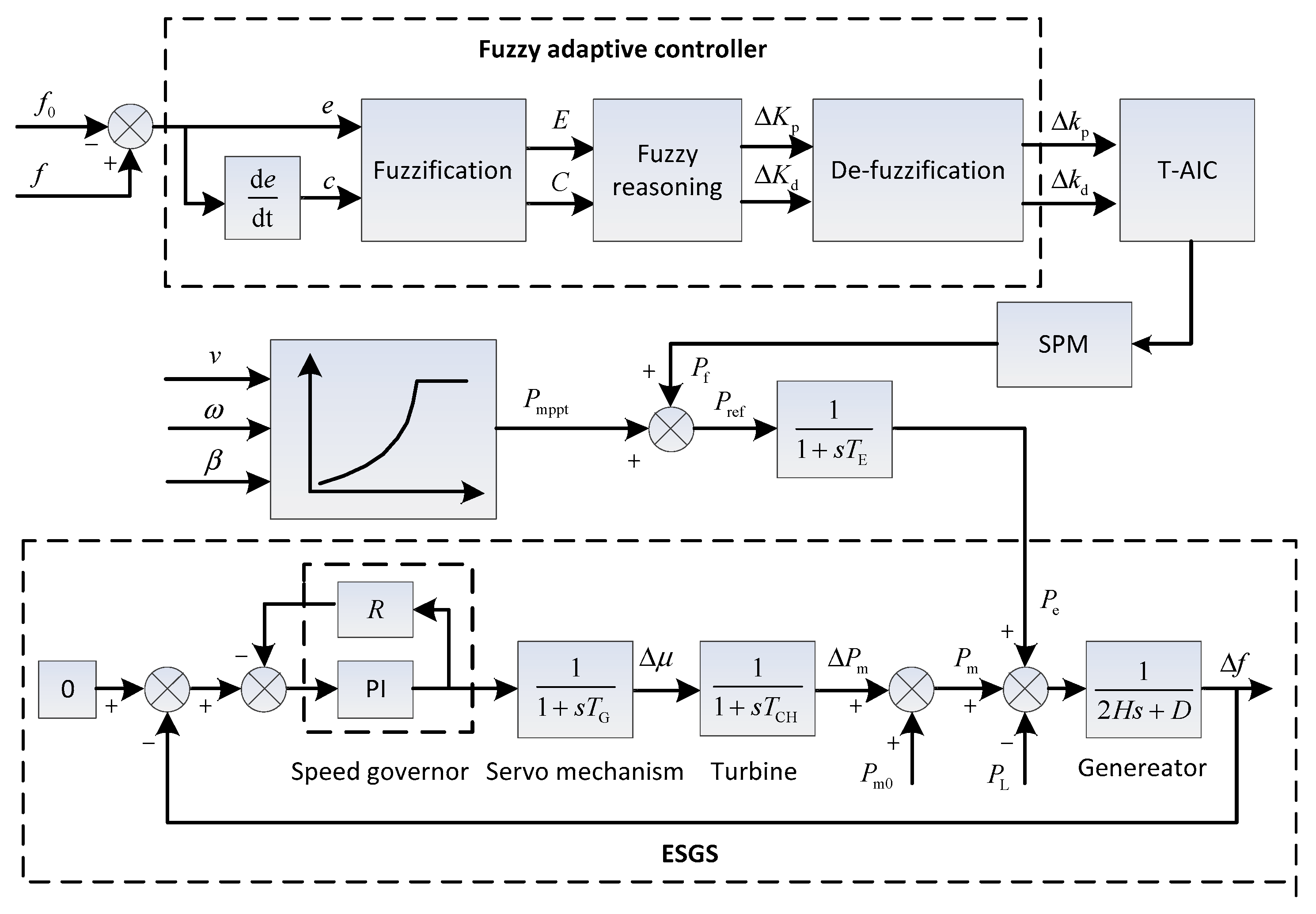
The whole structure diagram of the grid-connected system with a fuzzy adaptive controller (FA-AIC) is given in Figure 5. As shown, the fuzzy adaptive controller has three blocks: Fuzzification; fuzzy reasoning; and de-fuzzification. Correspondingly, a fuzzy adaptive controller design for a practical dynamical system comprises three steps:
- (1)
- The system dynamic characteristics and behaviors need to be understood comprehensively; the system states and inputs/outputs control variables and variation ranges need to be determined; the appropriate fuzzy membership functions and fuzzy sets are produced for all inputs/outputs and accomplish fuzzification.
- (2)
- A proper fuzzy reasoning mechanism is defined and the fuzzy rules are established depending on the logical relationships between the inputs and outputs.
- (3)
- The de-fuzzification method is determined, the outputs are de-fuzzified applying fuzzy rules.
5.1. Fuzzification
Fuzzification is a mapping process that converts the crisp value of the inputs and outputs into linguistic variables applying fuzzy membership functions. In this paper, the grid-connected system frequency deviation and the frequency deviation change rate are chosen as the inputs and respectively; the corrected values of the proportional and differential coefficient and are selected as the outputs respectively. In the fuzzy adaptive controller module in Figure 5, the inputs and are defined as:
The system frequency reference value is 50 Hz in this paper, and the primary frequency regulation range of the grid-connected system is set to ±101%, that is, 49.5 Hz~50.5 Hz, so the frequency deviation range is set as . The frequency deviation change rate after discrete sampling is set as . In order to ensure a certain reserved margin, based on the initial values of the proportional and derivative coefficients, the basic domain of outputs and are set as [−15, 5] and [−2, 2].
The triangular membership functions for the proposed controller are adopted. The five linguistic variables for the input variable and the output variable are negative big (NB), negative small (NS), zero (ZO), positive small (PS) and positive big (PB) whereas the input variable is indicated in the seven linguistic variables such as negative big (NB), negative medium (NM), negative small (NS), zero (ZO), positive small (PS), positive medium (PM), positive big (PB). The membership functions of the controller inputs and outputs are determined and shown in Figure 6.
5.2. Fuzzy Reasoning Mechanism:Fuzzy Rules Establishment
Fuzzy rules are established based on the logical relationships between the output and the input employing the Mamdani-type fuzzy reasoning mechanism, which can be described in the form of “IF/THEN” conditional statements. In this paper, when Both and are positive values, the grid-connected system frequency is getting worse, so both of and need to be take positive values and increase with the increasing of the inputs so as to enhance the additional inertia and suppress the system frequency deviation. When is positive and is negative, that indicates the system frequency is improving and both and should be set as negative and decrease as the input increases. If both and are negative, it means that the system frequency is in the process of reverse deterioration, so both of and are taken as positive values and increase with the increasing of the inputs. When is negative and is positive, it indicates that the system frequency is recovering, so both of and should be set as negative values and decrease as the input increases. According to the above logical relationships of outputs / with the behavior of the inputs /, two rule bases including 35 fuzzy rules are established and presented in Table 1.
For example:
Rule 1: IF is PS (positive small) and is PM (positive medium), THEN the output will be PM (positive medium). When the system frequency deviation is small and frequency deviation change rate is medium, a positive medium value is required for to increase the output power quickly and suppress the system frequency deviation.
Rule 2: IF is PB (positive big) and is PS (positive small), THEN the output is PB (positive big). The system frequency deviation is big and the frequency deviation change is small, it demands a positive big value for to respond to the frequency deviation change rate rapidly and to provide short-term power support.
Similarly, all other fuzzy rules are utilized in the view of the logical relationships between the inputs and outputs, and in this way, fuzzy inputs are converted into fuzzy outputs.
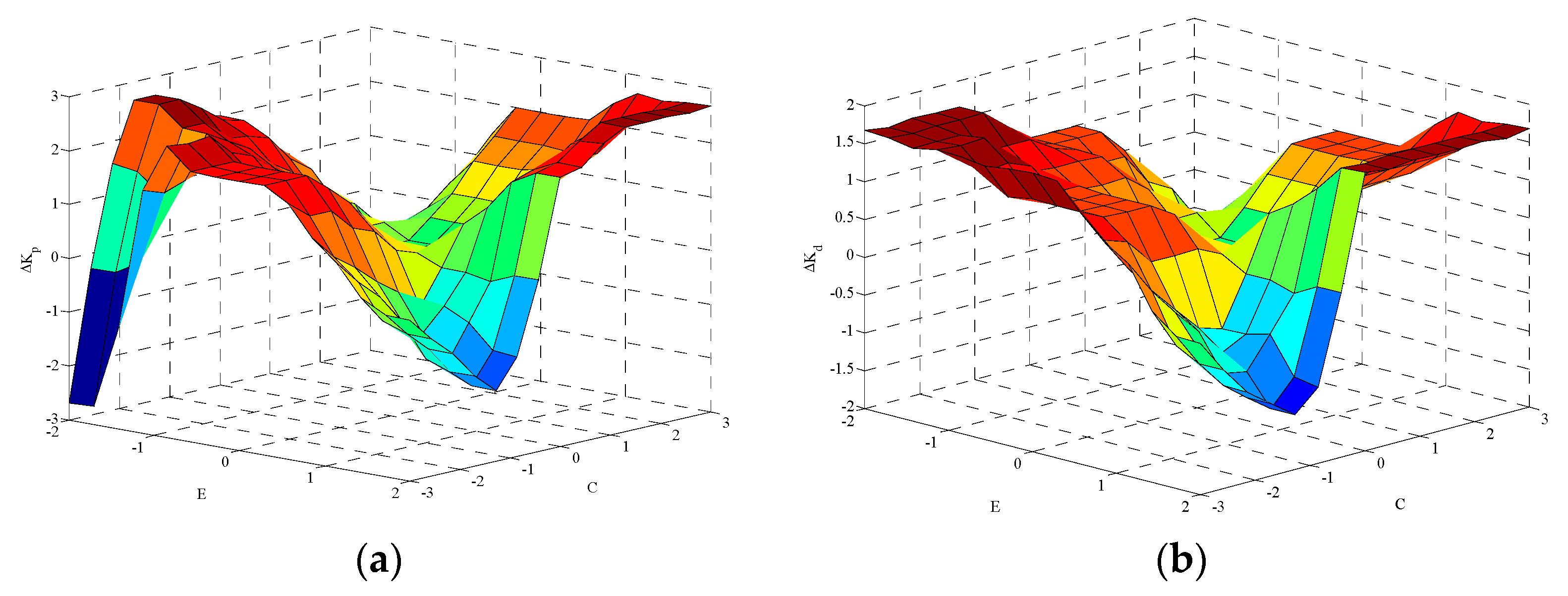
Figure 7 indicates the reasoning results corresponding to the fuzzy rules.
5.3. De-Fuzzification
The outputs and derived from the fuzzy adaptive controller are fuzzy in nature. In order to obtain the proper proportional and derivative coefficients and , de-fuzzification is demanded to convert the fuzzy variable into a crisp value. The commonly used de-fuzzification methods include the weighted average, the mom method, the centroid method and the mean-max. In this paper, the weighted average method is employed to de-fuzzify / to /.
6. Simulation Analysis
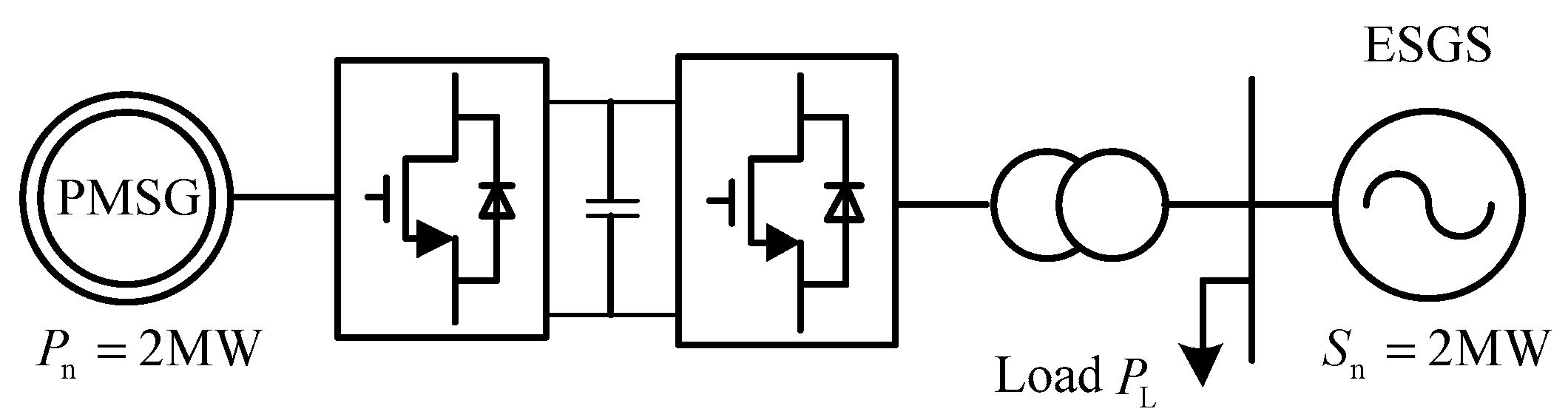
To verify the effectiveness of the FA-AIC, a simulation system composed of a D-PMSG and an ESGS has been built based on Matlab/Simulink platform. As shown in Figure 8, the partial parameters have been marked and the rest values of the simulation system have been summarized in Appendix A and Appendix B.
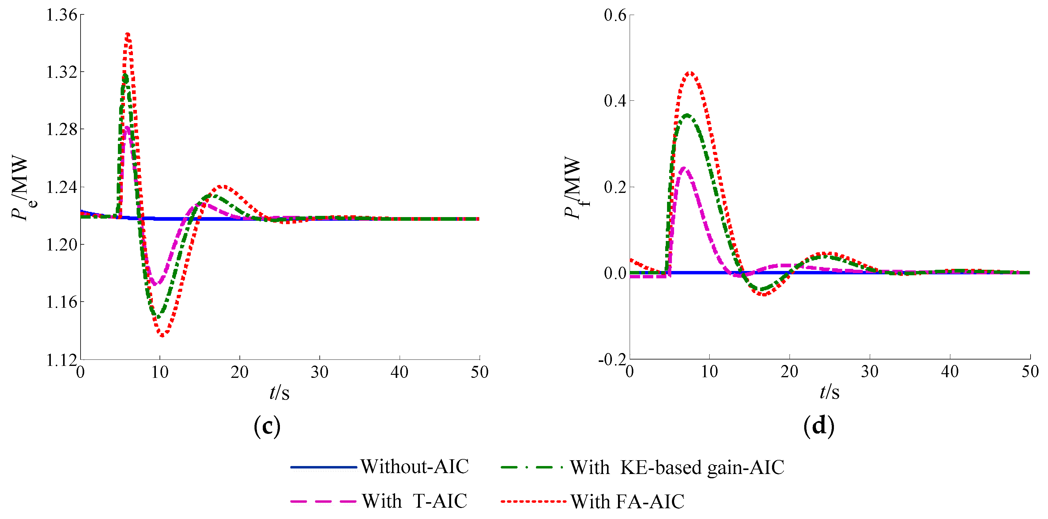
Three different cases have been designed to perform simulations and analysis, which are: (1) The wind speed is 8 m/s; (2) the wind speed is 10 m/s; (3) the variation in wind speed. Simulation tests were carried out to compare the frequency modulation effects under four different control strategies respectively: (1) Without additional inertial control (without-AIC); (2) the traditional additional inertial control (T-AIC); (3) the KE-based gain-AIC [26]; (4) the fuzzy adaptive additional inertial control (FA-AIC). Based on the system parameter values in Appendix A and Appendix B, the proportional and derivative coefficient initial values have been tuned as = 40, = 2.8.
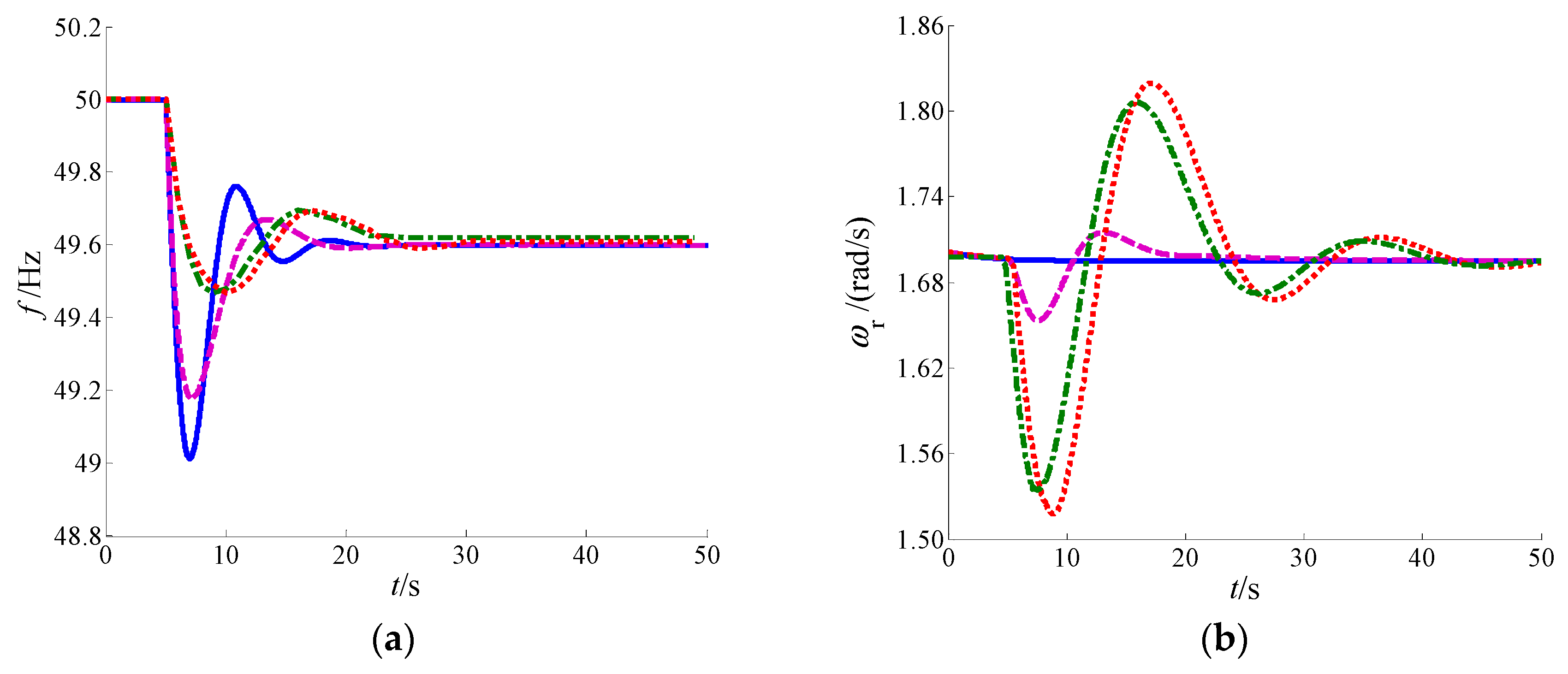
6.1. Case1: Sudden Load Changes when Wind Speed is 8 m/s
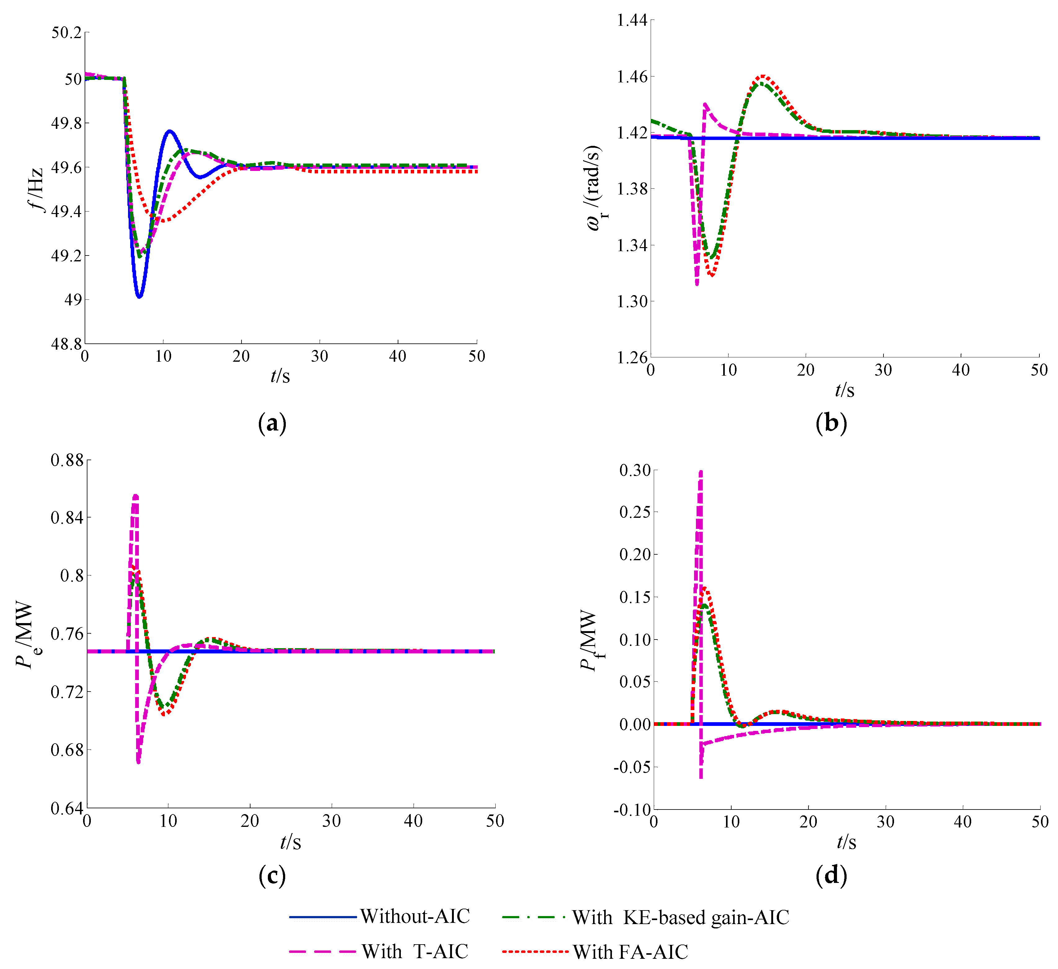
This case refers to the system inertial response when the active power of the load suddenly increases 0.4 MW in the first 5 s under the condition of constant wind speed that is 8 m/s. The other relevant parameters were selected as , . The dynamic responses of system variables are shown as Figure 9.
Figure 9a illustrates the comparisons of the system frequency response after the load suddenly increases and the partial data are shown in Table 2.
Based on the above conclusions, in the case of without the AIC, the D-PMSG operates in the MPPT control mode and shows a little improvement on the system frequency deviation. The introduction of the AIC can adjust the rotor speed and output power to make the D-PMSG participate in frequency responses and support frequency stability under the frequency fluctuation caused by the load disturbance.
In the T-AIC mode, the system frequency change rate decreases and the minimum value raises from 49.01 Hz to 49.22 Hz and the time for the system frequency minimum value extends from 6.96 s to 6.99 s. In the KE-based gain-AIC mode, the system frequency minimum value is 49.21 Hz, which is smaller than the T-AIC 0.01 Hz. This is because in the KE-based gain-AIC mode, the proportional and derivative coefficients are adjusted depending on the units’ initial rotor speed. The lower the rotor speed, the smaller the coefficients are, so the proportional and derivative coefficients in the T-AIC mode are larger than those in the KE-based gain-AIC. However, in the case of the FA-AIC, due to the introduction of the fuzzy adaptive controller, the two coefficients can be adjusted based on the frequency deviation and the frequency deviation change rate caused by the load disturbance, so the system frequency minimum value is further increased to 49.36 Hz and the time to the minimum value prolongs to 10.0 s. However, the system frequency steady-state response is hardly improved. Obviously, the system frequency dynamic response is improved significantly with the T-AIC, KE-based gain-AIC and the FA-AIC. In addition, compared with the T-AIC and the KE-based gain-AIC, the FA-AIC improves more. It can be seen that the FA-AIC theme can provide effective inertial support to improve the system inertia response and reduce the frequency change rate at the initial stage of the load disturbance.
Figure 9b–d compare the dynamic responses of the wind turbine speed , the wind turbine output active power and the auxiliary power thereunder the four control modes after the load suddenly increases. The D-PMSG operates in an optimal speed and an output power under the without-AIC mode. In case of the T-AIC, the proportional and derivative coefficients are the tuned initial values and relatively large, so the rotor speed decreases quickly and the auxiliary power increases rapidly in order to increase the wind turbine output power to participate in the system frequency regulation. However, the speed protection module (SPM) starts action and the AIC exits immediately when the rotor speed is less than 1.31 rad/s (0.67 ), the auxiliary power drops instantaneously and approaches to zero gradually. After that, the rotor speed returns to the optimal value thinly, that would cause the system to absorb electromagnetic power from the power grid and affect the system frequency response. In the KE-based gain-AIC mode, when the rotor speed is equal to the minimum value, and the two coefficients are zero, the unit does not provide inertial support and avoids the unit being off-grid. In the FA-AIC mode, the two coefficients and the auxiliary power are adjusted based on the frequency deviation and the frequency deviation change rate which avoid the frequency over-modulation for the wind turbine at low wind speeds. A comparison of the FA-AIC with the KE-based gain-AIC shows that the wind turbine speed is further reduced and the active power increases by 0.02 MW instantaneously after the load suddenly increases, and the rotor speed and the output power change smoothly overall.
6.2. Case 2: Sudden Load Changes when Wind Speed is 10 m/s
This case refers to the system inertial response when the active power of load increases 0.4 MW in the first 5 s under the condition of constant wind speed that is 10 m/s. The other relevant parameters remain constant. The simulation results are shown as Figure 10.
Figure 10a illustrates the comparisons of the system frequency response after the load suddenly increases and the partial data are shown in Table 3.
As in Case 1, the system frequency responses in the T-AIC, KE-based gain-AIC and the FA-AIC are improved more than the without-AIC mode. In addition, the proportional and derivative coefficients under the latter three modes are larger than those of Case 1.
In the T-AIC mode, the system frequency change rate decreases and the minimum value raises from 49.01 Hz to 49.20 Hz and the time to the system frequency minimum value extends from 6.96 s to 7.16 s. In the KE-based gain-AIC mode, the system frequency minimum value increased to 49.468 Hz and the time to the minimum value prolongs to 9.05 s, but the system frequency steady-state response obviously improved to 49.62 Hz. This is because the two coefficients are regulated according to the initial rotor speed under the larger wind speed, which are larger than those in the low wind speed. Therefore, the units’ rotor speed decreases more and the power participating in the frequency modulation are also more, which improves the system frequency response and the frequency regulation effect effectively. In the case of the FA-AIC, the two coefficients are adjusted adaptively under the frequency fluctuation caused by a load disturbance so as to provide inertia support for the system. Thus, the system frequency minimum value and the frequency change rate at the initial stage significantly improved, but the system frequency steady-state response hardly improved.
Figure 10b–d compare the dynamic responses of the wind turbine speed , the wind turbine output active power and the auxiliary power in the four control modes after the load suddenly increases. Compared with the other three control modes, the FA-AIC can make full use of the system inertia and release the D-PMSG frequency modulation potential to effectively improve the system frequency dynamic response and the regulation effect.
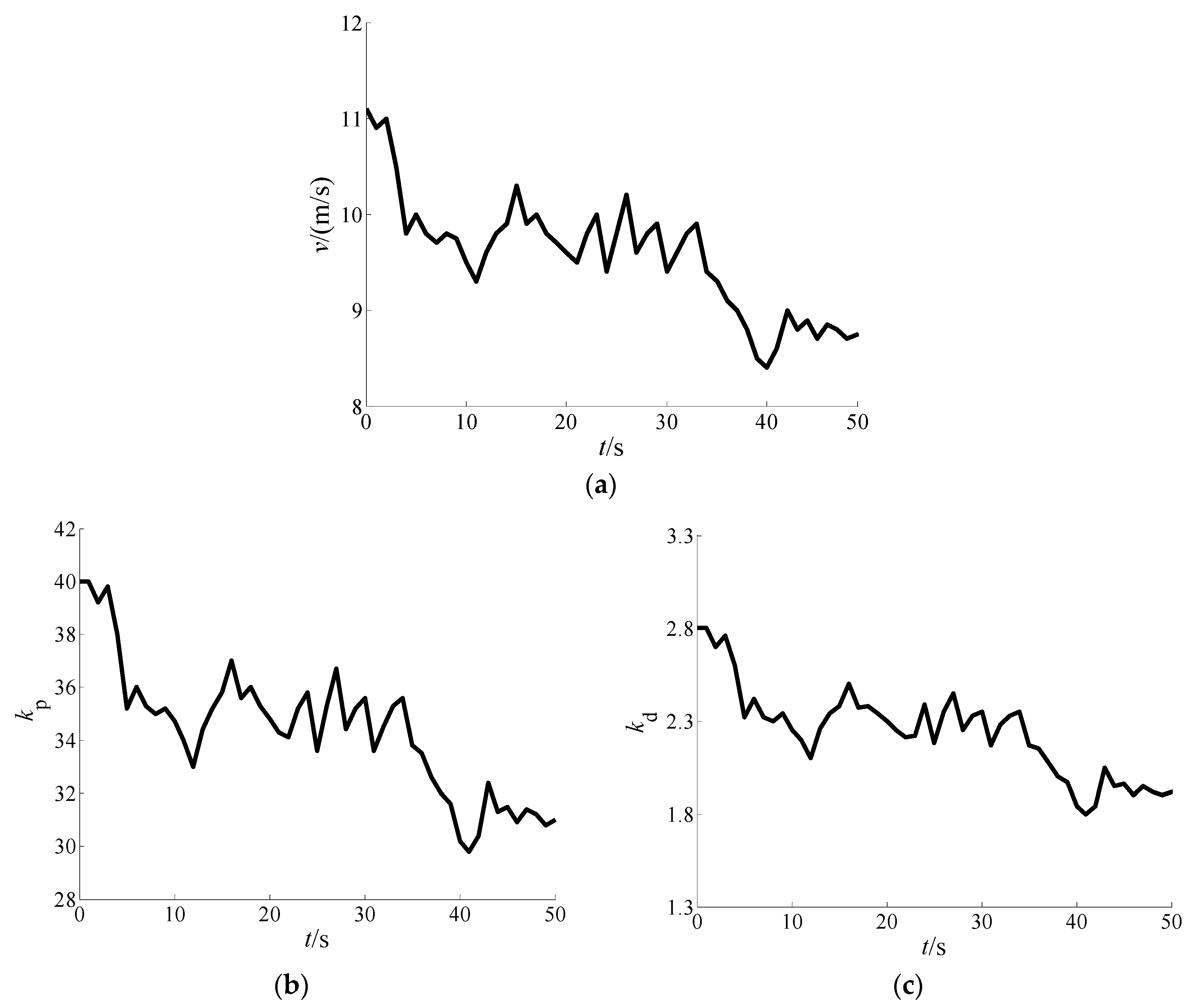
6.3. Case 3: Variation in Wind Speed
This case refers to the system inertial response when the active power of the load suddenly increases 0.4 MW in the first 20 s under the condition of random wind speed in 7~12 m/s. The other relevant parameters remain constant. The random wind speed waveform within 50 s is shown in Figure 11a.
Under the variation in wind speed, the proportional and derivative coefficients and are as shown in Figure 11b,c, and the appropriate control coefficients can be obtained according to the frequency deviation. Figure 11d indicates the rotor speed in three control modes under random wind speed and the load sudden disturbance. It can be seen that the D-PMSG wind turbine rotor speed with the KE-based gain-AIC and the FA-AIC are lower compared with the T-AIC, so more auxiliary power can be provided to support the system frequency. Figure 11e illustrates the comparisons of the system frequency response. Obviously, with the introduction of the KE-based gain-AIC and the FA-AIC, the system frequency can be smoothed by adaptively regulating the two coefficients to suppress the frequency fluctuation. When the load suddenly increases at 20 s, the system frequency minimum value with the T-AIC falls to 49.23 Hz and the ones with the KE-based gain-AIC and the FA-AIC rises to 49.49 Hz and 49.60 Hz respectively. The dynamic frequency deviation decreases greatly with the KE-based gain-AIC and the FA-AIC. In addition, compared with the KE-based gain-AIC, the FA-AIC improves more in the system frequency change rate and the minimum value at the initial stage. Obviously, the proposed FA-AIC strategy can not only suppress the frequency fluctuation caused by the variation in wind speed, but also provide rapid and effective frequency support during a load disturbance.
7. Conclusions
Based on a single-machine grid-connected system composed of a D-PMSG and an ESGS, this paper proposes a fuzzy adaptive additional inertial (FA-AIC) control strategy to improve the primary frequency regulation ability for the D-PMSG wind turbine. The simulation results indicate that the adoption of the T-AIC, KE-based gain-AIC and the FA-AIC can utilize the D-PMSG additional inertial response to provide frequency support under load and wind speed disturbances. Compared with the T-AIC and the KE-based gain-AIC, the proposed FA-AIC adjusts the proportional and derivative coefficients adaptively based on the system frequency deviation and the frequency deviation change rate under load or wind speed disturbances. This proposed system can not only provide rapid and effective frequency support during load disturbances, but also suppress frequency fluctuations caused by wind speed changes and further, it displays a better dynamic frequency modulation effect.
Author Contributions
M.L. and Y.W. conceived the research; M.L. performed the simulation and validation of the model, performed the controller design and wrote the paper; Y.W. critically revised the paper and provided constructive criticism.
Funding
This work is supported by the Fundamental Research Funds for the Central Universities (9161715008).
Conflicts of Interest
The authors declare no conflicts of interest.
Appendix A

Table A1.
D-PMSG wind turbine parameters.
| Parameter | Symbol | Value |
|---|---|---|
| Radius of the rotor | 38 m | |
| Air density | 1.225 kg/m3 | |
| Rated rotor speed | 1.956 rad/s | |
| Rated power | 2 MW | |
| Cut in wind speed | 3 m/s | |
| Rated wind speed | 11.8 m/s | |
| Cut out wind speed | 25 m/s | |
| Optimal tip speed ratio | 6.3 | |
| Nominal power coefficient | 0.438 | |
| Moment inertia constant | 1.5 × 10⁶ kg m2 | |
| pitch servo time constant | 0.2 s | |
| Min./Max. pitch angle | 0°/30° | |
| Blade pitch angle rate | −10°/s/10°/s | |
| PMSG-converter equivalent time constant | 0.2 s |
Appendix B
Table A2.
Speed governor, turbine and synchronous generator parameters.
| Parameter | Symbol | Value |
|---|---|---|
| PI controller gains | 10/10 | |
| Difference coefficient | 0.025 | |
| Servo inertia time constant | 0.2 s | |
| Turbine inertia time constant | 0.3 s | |
| Synchronous generator inertia time constant | 6 s | |
| Synchronous generator damping coefficient | 0 |
References
- Global Wind Energy Outlook. 2017. Available online: http://www.gwec.net (accessed on 20 December 2018).
- Huenteler, J.; Niebuhr, C.; Schmidt, T.S. The effect of local and global learning on the cost of renewable energy in developing countries. J. Clean. Prod. 2016, 128, 6–21. [Google Scholar] [CrossRef]
- Lind, P.G.; Vera-Tudela, L.; Wächter, M.; Kühn, M.; Peinke, J. Normal behavior models for wind turbine vibrations: Comparison of neural networks and a stochastic approach. Energies 2017, 10, 1944. [Google Scholar] [CrossRef]
- Khater, F.; Omar, A. A Review of Direct Driven PMSG for Wind Energy Systems. J. Energy Power Eng. 2013, 7, 1592–1603. [Google Scholar]
- Li, S.; Haskew, T.A.; Xu, L. Conventional and novel control designs for direct driven PMSG wind turbines. Electr. Power Syst. Res. 2010, 80, 328–338. [Google Scholar] [CrossRef]
- Fu, Y.; Wang, Y.; Zhang, X.; Luo, Y. Analysis and Integrated Control of Inertia and Primary Frequency Regulation for Variable Speed Wind Turbines. Proc. CSEE 2014, 34, 4706–4716. [Google Scholar]
- Mohamed, A.; Ralph, K. Fault-Ride through Strategy for Permanent-Magnet Synchronous Generators in Variable-Speed Wind Turbines. Energies 2016, 9, 1066. [Google Scholar]
- Hong, C.M.; Chen, C.H.; Tu, C.S. Maximum power point tracking-based control algorithm for PMSG wind generation system without mechanical sensors. Energy Convers. Manag. 2013, 69, 58–67. [Google Scholar] [CrossRef]
- Doherty, R.; Mullane, A.; Nolan, G.; Burke, D.; Bryson, A.; O’Malley, M. An assessment of the impact of wind generation on system frequency control. IEEE Trans. Power Syst. 2010, 25, 452–460. [Google Scholar] [CrossRef]
- Arani, M.F.M.; Mohamed, Y.A.R.I. Analysis and mitigation of undesirable impacts of implementing frequency support controllers in wind power generation. IEEE Trans. Energy Convers. 2016, 31, 174–186. [Google Scholar] [CrossRef]
- Ullah, N.R.; Thiringer, T.; Karlsson, D. Temporary primary frequency control support by variable speed wind turbines potential and applications. IEEE Trans. Power Syst. 2008, 23, 601–612. [Google Scholar] [CrossRef]
- Morren, J.; De Haan, S.W.; Kling, W.L.; Ferreira, J.A. Wind turbine simulating inertia and supporting primary frequency control. IEEE Trans. Power Syst. 2006, 21, 433–434. [Google Scholar] [CrossRef]
- Wang, Y.; Bayem, H.; Giralt-Devant, M.; Silva, V.; Guillaud, X.; Francois, B. Methods for assessing available wind primary power reserve. IEEE Trans. Sustain. Energy 2015, 6, 272–280. [Google Scholar] [CrossRef]
- Rawn, B.G.; Lehn, P.W.; Maggiore, M. Control Methodology to Mitigate the Grid Impact of Wind Turbines. IEEE Trans. Energy Convers. 2007, 22, 431–438. [Google Scholar] [CrossRef]
- Mauricio, J.; Marano, A.; Gomez-Exposito, A.; Ramos, J.L.M. Frequency Regulation Contribution Through Variable-Speed Wind Energy Conversion Systems. IEEE Trans. Power Syst. 2009, 24, 173–180. [Google Scholar] [CrossRef]
- Wu, Z.; Gao, W.; Wang, X.; Kang, M.; Hwang, M.; Kang, Y.C.; Gevogian, V.; Muljadi, E.; Gevorgian, V. Improved inertial control for permanent magnet synchronous generator wind turbine generators. IET Renew. Power Gener. 2016, 10, 1366–1373. [Google Scholar] [CrossRef]
- Wang, Y.; Meng, J.; Zhang, X.; Xu, L. Control of PMSG-based wind turbines for system Inertial response and power oscillation damping. IEEE Trans. Sustain. Energy 2015, 6, 565–574. [Google Scholar] [CrossRef]
- Liu, J.; Yao, W.; Wen, J.; Huang, Y.; Liu, Y. Prospect of technology for large-scale wind farm participating into power grid frequency regulation. Power Syst. Technol. 2014, 38, 638–646. [Google Scholar]
- Josephine, R.; Suja, S. Estimating PMSG wind turbines by inertia and droop control schemes with intelligent fuzzy controller in Indian development. J. Electr. Eng. Technol. 2014, 9, 1196–1201. [Google Scholar] [CrossRef]
- Vidyanandan, K.V.; Senroy, N. Primary frequency regulation by deloaded wind turbines using variable droop. IEEE Trans. Power Syst. 2013, 28, 837–846. [Google Scholar] [CrossRef]
- Tian, X.; Wang, W.; Chi, Y. Variable parameter virtual inertia control based on effective energy storage of DFIG-based wind turbines. Autom. Electr. Power Syst. 2015, 39, 20–26. [Google Scholar]
- Pan, W.; Quan, R.; Wang, F. A variable droop control strategy for doubly-fed induction generators. Autom. Electr. Power Syst. 2015, 49, 126–132. [Google Scholar]
- Zhao, J.; Lv, X.; Fu, Y.; Hu, X.G. Frequency regulation of the wind/photovoltaic/diesel microgrid based on DFIG cooperative strategy with variable coefficients between virtual inertia and over-speed control. Trans. China Electrotech. Soc. 2015, 30, 59–68. [Google Scholar]
- Chen, Y.; Wang, G.; Shi, Q.; Fu, L.; Jiang, W. A new coordinated virtual inertia control strategy for wind turbines. Autom. Electr. Power Syst. 2015, 39, 27–33. [Google Scholar]
- Martínez-Lucas, G.; Sarasúa, J.I.; Sánchez-Fernández, J. Frequency Regulation of a Hybrid Wind-Hydro Power Plant in an Isolated Power System. Energies 2018, 11, 239. [Google Scholar] [CrossRef]
- Lee, J.; Muljadi, E.; Srensen, P.; Kang, Y.C. Releasable kinetic energy-based inertial control of a DFIG wind power plant. IEEE Trans. Sustain. Energy 2016, 7, 279–288. [Google Scholar] [CrossRef]
- Birch, A.P.; Sapeluk, A.T.; Ozveren, C.S. An enhanced neural network load frequency control technique. In Proceedings of the International Conference on Control (Control ’94), Coventry, UK, 21–24 March 1994; p. 389. [Google Scholar]
- Farhangi, R.; Boroushaki, M.; Hosseini, H. Load-frequency control of interconnected power system suing emotional learning-based intelligent controller. Electr. Power Energy Syst. 2012, 36, 76–83. [Google Scholar] [CrossRef]
- Kerdphol, T.; Qudaih, Y.; Watanabe, M.; Mitani, Y. RBF neural network-based online intelligent management of a battery energy storage system for stand-alone microgrids. Energy Sustain. Soc. 2016, 6, 5. [Google Scholar] [CrossRef]
- Kerdphol, T.; Rahman, F.; Mitani, Y.; Hongesombut, K.; Küfeoğlu, S. Virtual Inertia Control-Based Model Predictive Control for Microgrid Frequency Stabilization Considering High Renewable Energy Integration. Sustainability 2017, 9, 773. [Google Scholar] [CrossRef]
- Cam, E.; Kocaarslan, I. Load frequency control in two area power systems using fuzzy logic controller. Energy Convers. Manag. 2005, 46, 233–243. [Google Scholar] [CrossRef]
- Ronilaya, F.; Miyauchi, H. A Load Frequency Control in an Off-Grid Sustainable Power System Based on a Parameter Adaptive PID-Type Fuzzy Controller. Int. J. Emerg. Electr. Power Syst. 2014, 15, 429–441. [Google Scholar] [CrossRef]
- Abazari, A.; Dozein, M.G.; Monsef, H. An optimal Fuzzy-logic based frequency control strategy in a high wind penetrated power system. J. Frankl. Inst. 2018, 355, 6262–6285. [Google Scholar] [CrossRef]
- Peng, B.; Zhang, F.; Liang, J.; Ding, L.; Liang, Z.; Wu, Q. Coordinated control strategy for the short-term frequency response of a DFIG-ES system based on wind speed zone classification and fuzzy logic control. Electr. Power Energy Syst. 2019, 107, 363–378. [Google Scholar] [CrossRef]
- Akel, F.; Ghennam, T.; Berkouk, E.; Laour, M. An improved sensorless decoupled power control scheme of grid connected variable speed wind turbine generator. Energy Convers. Manag. 2014, 78, 584–594. [Google Scholar] [CrossRef]
- Li, L.; Ye, L. Coordinated control of frequency and rotational speed for direct drive permanent magnet synchronous generator wind speed. Autom. Electr. Power Syst. 2011, 35, 26–31. [Google Scholar]
- Liu, Q.; Han, X. Main steps and key technology of the simplified model for doubly-fed induction generator. East China Electr. Power 2014, 42, 0840–0845. [Google Scholar]
- Song, Y. Research on Modeling and Control Strategy for the Direct-Driven Permanent-Magnet Generator. Master’s Thesis, North China Electric Power University, Baoding, China, 2013; p. 3. [Google Scholar]
- Geng, H.; Xu, D. Stability analysis and improvements for variable-speed multi pole permanent magnet synchronous generator-based wind energy conversion system. IEEE Trans. Sustain. Energy 2011, 2, 459–467. [Google Scholar] [CrossRef]
- Keung, P.K.; Li, P.; Banakar, H.; Ooi, B.T. Kinetic energy of wind-turbine generators for system frequency support. IEEE Trans. Power Syst. 2009, 24, 279–287. [Google Scholar] [CrossRef]
- Liu, J.; Yao, Q.; Liu, Y.; Hu, Y. Wind Farm Primary Frequency Control Strategy Based on Wind &Thermal Power. Proc. CSEE 2017, 37, 3462–3469. [Google Scholar]
Figure 1.
The simplified model of the permanent magnet synchronous generator (D-PMSG).

Figure 2.
The maximum power point tracking (MPPT) control structure diagram.

Figure 3.
The variable pitch control structure diagram.

Figure 4.
Structure diagram of the additional inertia control principle.

Figure 5.
The whole structure diagram of grid-connected system with a fuzzy adaptive additional inertia control (FA-AIC).
Figure 5.
The whole structure diagram of grid-connected system with a fuzzy adaptive additional inertia control (FA-AIC).

Figure 6.
The membership functions of the inputs and outputs. (a) The membership function of e; (b) The membership function of c; (c) The membership function of ; (d) The membership function of .
Figure 6.
The membership functions of the inputs and outputs. (a) The membership function of e; (b) The membership function of c; (c) The membership function of ; (d) The membership function of .

Figure 7.
Fuzzy reasoning results. (a) Reasoning result of ; (b) Reasoning result of .

Figure 8.
The typical structure of the permanent magnet synchronous generator (D-PMSG) grid-connected system.
Figure 8.
The typical structure of the permanent magnet synchronous generator (D-PMSG) grid-connected system.

Figure 9.
Comparisons of the system variable responses when wind speed is 8 m/s. (a) System frequency response; (b) Wind turbine speed; (c) Wind turbine output active power; (d) Auxiliary power.
Figure 9.
Comparisons of the system variable responses when wind speed is 8 m/s. (a) System frequency response; (b) Wind turbine speed; (c) Wind turbine output active power; (d) Auxiliary power.

Figure 10.
Comparisons of system variable responses when the wind speed is 10 m/s. (a) System frequency response; (b) Wind turbine speed; (c) Wind turbine output active power; (d) Auxiliary power.
Figure 10.
Comparisons of system variable responses when the wind speed is 10 m/s. (a) System frequency response; (b) Wind turbine speed; (c) Wind turbine output active power; (d) Auxiliary power.


Figure 11.
The control effects in the random wind speed. (a) Wind speed waveform; (b) Proportional coefficient value; (c) Derivative coefficient value; (d) Wind turbine speed; (e) System frequency response.
Figure 11.
The control effects in the random wind speed. (a) Wind speed waveform; (b) Proportional coefficient value; (c) Derivative coefficient value; (d) Wind turbine speed; (e) System frequency response.


Table 1.
Fuzzy roles of ∆Kp and ∆Kd.
| E | NB | NS | ZO | PS | PB | ||
| C | |||||||
| NB | PB | PB | PM | PS | ZO | ||
| NM | PB | PB | PM | ZO | NS | ||
| NS | PB | PM | PS | NS | NM | ||
| ZO | PM | PS | ZO | PS | PM | ||
| PS | PS | ZO | ZO | PS | PB | ||
| PM | ZO | NS | PS | PM | PB | ||
| PB | NS | ZO | PM | PB | PB | ||
| E | NB | NS | ZO | PS | PB | ||
| C | |||||||
| NB | PB | PB | PB | PS | ZO | ||
| NM | PB | PS | PS | ZO | NS | ||
| NS | PB | PS | PS | NS | NB | ||
| ZO | PS | PS | ZO | PS | PB | ||
| PS | PS | ZO | ZO | PS | PB | ||
| PM | ZO | NS | PS | PS | PB | ||
| PB | NB | ZO | PS | PB | PB | ||
Table 2.
Comparisons of the system frequency response.
| Control Mode | fmin/Hz | tmin/s | f∞/Hz | t∞/s |
|---|---|---|---|---|
| Without-AIC | 49.01 | 6.96 | 49.60 | 16.65 |
| T-AIC | 49.22 | 6.99 | 49.60 | 17.74 |
| KE-based gain-AIC | 49.21 | 6.72 | 49.60 | 18.68 |
| FA-AIC | 49.36 | 10.0 | 49.58 | 24.20 |
Notes: are system frequency minimum value, time to system frequency minimum value, system frequency steady-state value, system frequency setting time, respectively.
Table 3.
Comparisons of the system frequency response.
| Control Mode | fmin/Hz | tmin/s | f∞/Hz | t∞/s |
|---|---|---|---|---|
| Without-AIC | 49.01 | 6.96 | 49.60 | 18.02 |
| T-AIC | 49.20 | 7.16 | 49.60 | 20.18 |
| KE-based gain-AIC | 49.468 | 9.05 | 49.62 | 22.43 |
| FA-AIC | 49.47 | 10.12 | 49.61 | 24.26 |
© 2019 by the authors. Licensee MDPI, Basel, Switzerland. This article is an open access article distributed under the terms and conditions of the Creative Commons Attribution (CC BY) license (http://creativecommons.org/licenses/by/4.0/).
Share and Cite
MDPI and ACS Style
Li, M.; Wang, Y. Research on Frequency Fuzzy Adaptive Additional Inertial Control Strategy for D-PMSG Wind Turbine. Sustainability 2019, 11, 4241. https://0-doi-org.brum.beds.ac.uk/10.3390/su11154241
AMA Style
Li M, Wang Y. Research on Frequency Fuzzy Adaptive Additional Inertial Control Strategy for D-PMSG Wind Turbine. Sustainability. 2019; 11(15):4241. https://0-doi-org.brum.beds.ac.uk/10.3390/su11154241
Chicago/Turabian StyleLi, Mudan, and Yinsong Wang. 2019. "Research on Frequency Fuzzy Adaptive Additional Inertial Control Strategy for D-PMSG Wind Turbine" Sustainability 11, no. 15: 4241. https://0-doi-org.brum.beds.ac.uk/10.3390/su11154241
Note that from the first issue of 2016, this journal uses article numbers instead of page numbers. See further details here.