Optimum Design and Energy Performance of Hybrid Triple Glazing System with Vacuum and Carbon Dioxide Filled Gap


1
Industry Academic Cooperation Foundation, Hankyong National University, 327, Jungang-ro, Anseong-si, Gyeonggi-do 17579, Korea
2
School of Architecture, Hankyong National University, 327, Jungang-ro, Anseong-si, Gyeonggi-do 17579, Korea
*
Author to whom correspondence should be addressed.
Sustainability 2019, 11(19), 5543; https://0-doi-org.brum.beds.ac.uk/10.3390/su11195543
Submission received: 5 September 2019
/
Revised: 20 September 2019
/
Accepted: 7 October 2019
/
Published: 8 October 2019
(This article belongs to the Section Sustainable Engineering and Science)
Abstract
:This study develops a hybrid triple glazing technology that combines vacuum and carbon dioxide (CO2) gaps to help store CO2 in buildings. We determine the optimal thickness of glazing and calculate its thermal transmission (U-value). The amount of energy saved by using the proposed glazing system is then compared with that when using conventional insulating gases (air, argon, and krypton). Therm & Window, a modeling and analysis program for glazing, and EnergyPlus, a building environment and energy evaluation program, were used for the analysis. The optimal thickness determined for the vacuum and CO2 sections is 6.2 mm and 19 mm, respectively. The latter section comprises a 15-mm CO2 gap and 4 mm of glass. The total thickness of the glazing is 25.2 mm and the U-value is 0.259 W/m2∙K. The energy performance of the triple glazing using vacuum and CO2 gaps is between that of glazing using vacuum and air and that using vacuum and krypton gas gaps. Further, its performance is comparable to that of triple glazing using vacuum and argon gas gaps. Therefore, the hybrid triple glazing proposed in this paper represents an advanced glazing technique that can absorb CO2 and reduce energy consumption in buildings.
1. Introduction
Recent developments in super-insulating glazing with extremely low heat transmittances (U-values) have minimized heat transfer through windows installed on the outer walls of buildings. In addition, new glazing materials and technologies have been applied to replace existing glazing elements such as clear glass, insulating gas, and aluminum-based edge sealing. Previous research has reported glazing U-values that are similar or superior to those of the outer wall [1,2].
These advanced glazing types can be divided into eight categories. The first involves retrofitting conventional glazing to include high-insulation multi-layer glazing comprising a low-emission coating, a nonmetal-based edge sealing, and argon (Ar) and krypton (Kr) gases instead of conventional clear gas and air as insulating gases [3]. Vacuum glazing is a unique technology that does not contain adiabatic gases. The glazing forms a vacuum between panes of glass and generates minimal heat transfer by convection or radiation. The second is triple vacuum glazing comprising three sheets of glass and two vacuum gaps with a low-emission coating. This exhibits the lowest U-value among all current glazing systems [4,5]. In the third type, a high-insulating film is inserted into the gas gaps of suspending glazing, which leads to considerably low U-values for low the glazing thicknesses. This type of glazing is also less expensive than other types of glazing and effectively reduces energy consumption in buildings with high window area ratios or with windows enclosed by a curtain wall [6,7]. The fourth type is electrochromic glazing, which has recently been developed as a smart glazing technique that can drastically reduce building energy consumption by varying the color of the glass according to the intensity of the external solar radiation and controlling the U-value and solar heat gain coefficient (SHGC) of the glazing [8,9,10]. Fifth, phase change material (PCM) is a high-performance latent heat storage material that stores more thermal energy than other materials. Recently, studies have attempted to reduce the energy consumption of buildings by integrating PCMs with building envelopes [11], for example, by injecting PCM into the glazing gas gap. If a PCM is applied to the gas gap of glazing, it will considerably reduce energy loss by preventing sudden variations in the surface temperature [12,13]. The sixth type is photovoltaic (PV) glazing, which combines glazing with PV modules to provide both shade and energy. Although its U-value is slightly higher than those of other glazing types, PV glazing is versatile and multipurpose [14,15,16]. The seventh type is self-cleaning glazing that can self-clean contaminants adhering to the glass surface such as dust or stains from organic materials. Because a TiO2 photocatalyst coating is installed on the glass, the glass surface is cleaned via ultraviolet rays and rainwater and does not require artificial cleaning [17,18,19]. The final type is aerogel glazing comprising aerogels. In this type, granular silica-based super-insulated materials are inserted into the gas gap. This glazing can almost completely block indoor and outdoor heat flow, is thinner and lighter than other glazing types, and exhibits excellent thermal insulation performance. However, because aerogels exhibit poor strength and are easily destroyed when they come in contact with water, further research is required to compensate for their limitations in glazing applications [20,21].
Table 1 lists the U-values of these advanced glazing types determined in previous studies. These U-values were measured at the center of the glazing system, which was composed of glass, gaps, and edge sealings. Vacuum and suspended glazing had the lowest U-values of 0.24 W/m2∙K and 0.28 W/m2∙K, respectively, whereas self-cleaning and PV glazing had sufficiently high U-values because they focused on energy production, shading, and maintenance rather than insulation.
This paper proposes novel hybrid triple glazing consisting of carbon dioxide (CO2) and vacuum gaps. Previous studies have demonstrated that a vacuum gap can drastically reduce the U-value of the glazing system by including adiabatic gas. They have also suggested optimal designs and thicknesses. Moreover, as a greenhouse gas with the greatest impact on global warming, CO2 is strictly regulated both domestically and internationally. However, the development of CO2 capture and utilization (CCU) technology has enabled the use of CO2 as a resource in industries, instead of simple artificial control of CO2 through capture and storage (CCS) technology [22,23,24]. As an example of CCU technology, the proposed glazing system uses captured pure CO2 gas as the glazing insulation gas. Because glazing involving an insulation gas requires edge sealing technology to seal the gas gap, there is a slight risk of CO2 gas being released into the atmosphere. Moreover, our previous studies have confirmed that the insulation performance of pure CO2 gas is similar to that of Ar gas [25]. If CO2 can replace expensive Ar gas, it will significantly reduce the price of both glazing and windows. In addition, the majority of the captured CO2 gas is buried in the ground, which is a costly process [23]. If CO2 is used for glazing in buildings, the building itself could function as a CO2 sink, similar to land and forests. As all buildings typically have a relatively large glazing area, not only will a vast amount of CO2 be absorbed, but CO2 processing costs will also be reduced.
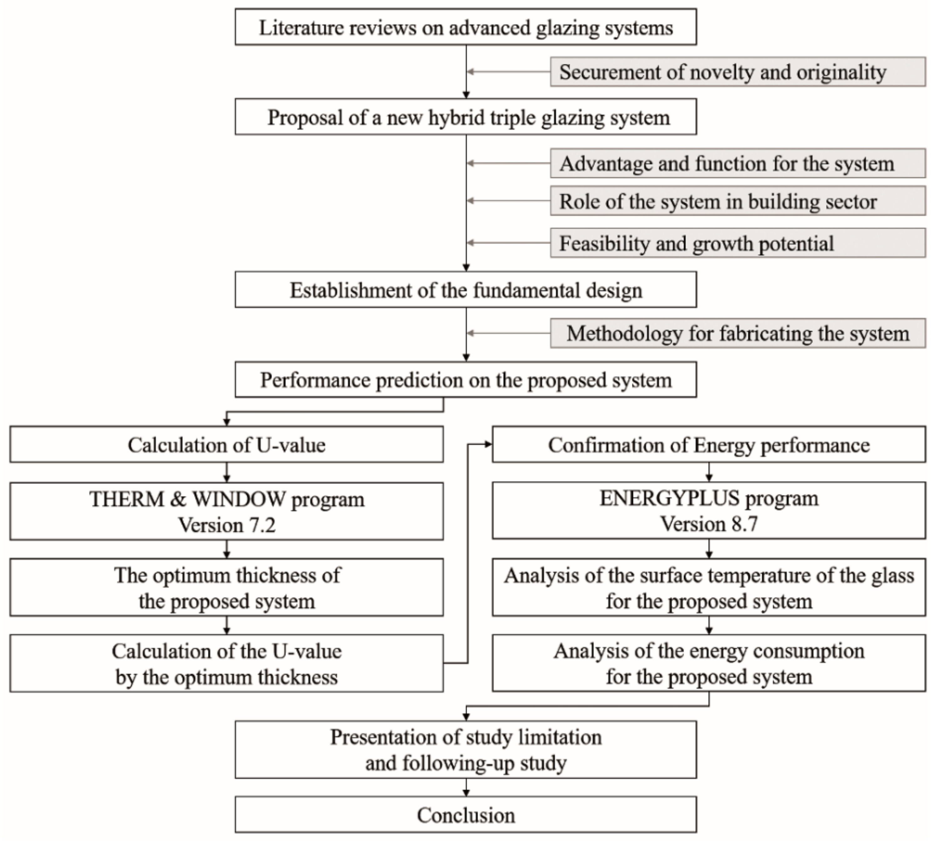
This paper presents early research results on the development of the proposed hybrid triple glazing system. The study had two key objectives: To derive the optimal thickness and U-value of the proposed glazing system and to determine the potential energy savings [26,27] for a building comprising the proposed glazing. Two computer simulation programs were used to derive the results. The U-value and optimal thickness of the proposed glazing were calculated using the Therm & Window version 7.2 [28,29] and the energy performance of the glazing [3,30] was evaluated using EnergyPlus 8.7 [31,32]. Figure 1 shows a flow chart of this study.
2. Materials and Methods
2.1. Structure of Hybrid Triple Glazing System
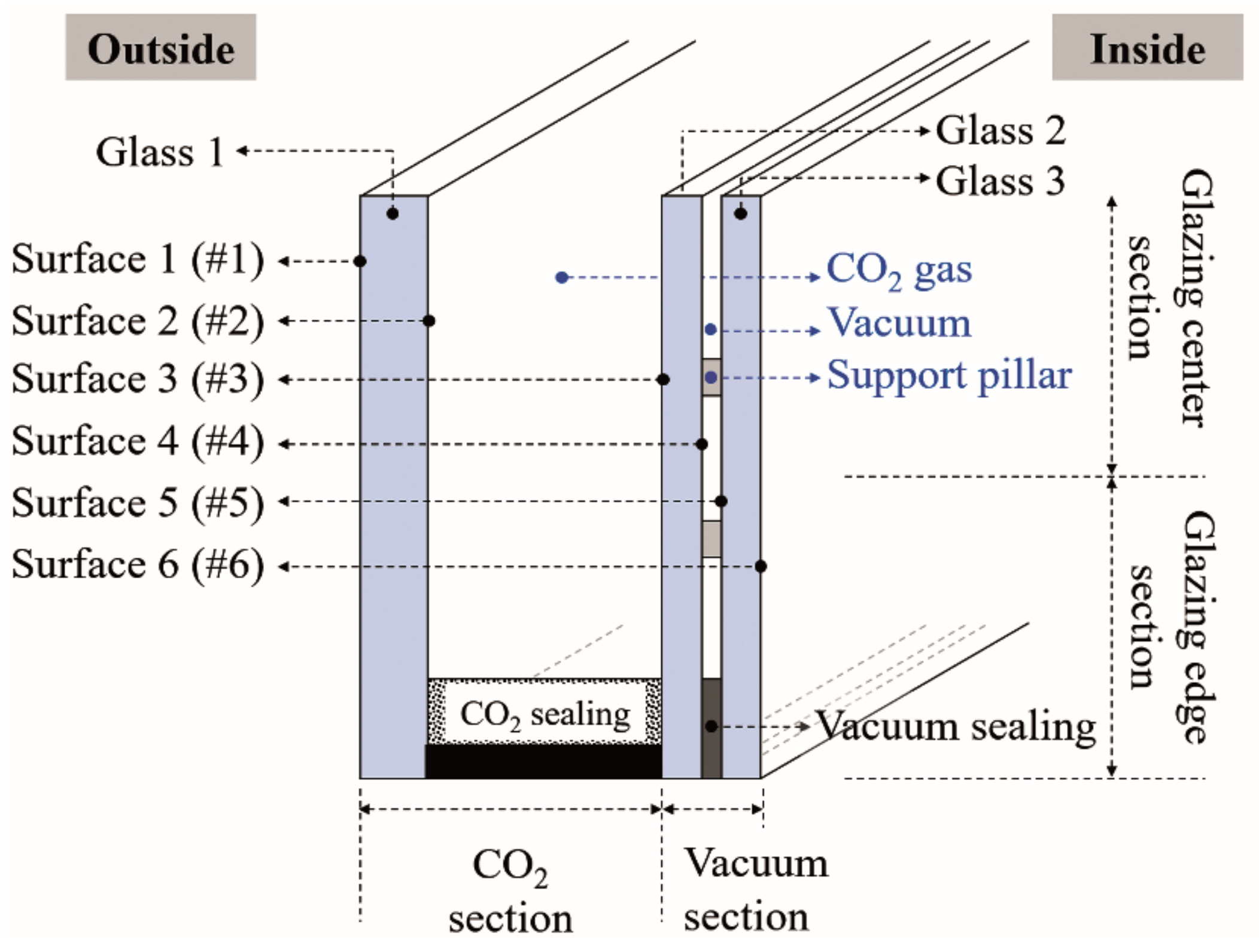
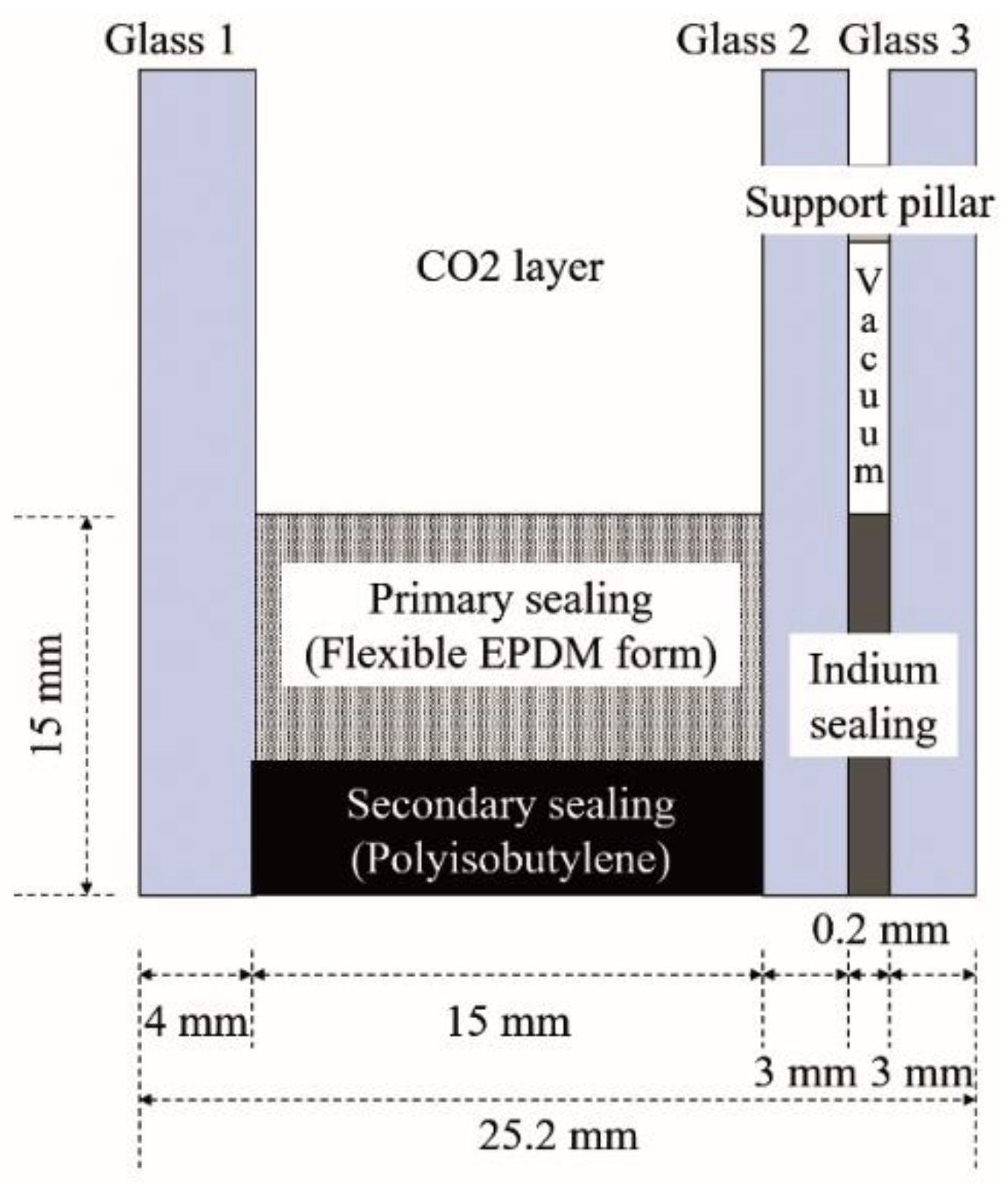
The structure of the proposed hybrid triple glazing system is shown in Figure 2. It is divided into a vacuum section and a CO2 section. The vacuum section comprises two sheets of glass, a vacuum gap with support pillar, and vacuum edge sealing, whereas the CO2 section comprises a single glass and CO2 gap and insulating edge sealing. The vacuum section is installed on the interior side of the window and the CO2 section is installed on the outer side. The sections use different edge sealing technologies depending on the characteristics of the gas gap.
2.2. Elements of the Vacuum Section
Table 2 lists the characteristics of the glass employed in the vacuum section. The Lawrence Berkeley National Laboratory, which distributes the Therm & Window program, provides data on a majority of products produced by global glass manufacturers and regularly updates them in a simulation program [28]. In this study, the simulation employed low-conductivity glass with a low-emission coat on one side of the surface, manufactured by Saint-Gobain Glass Ltd. The optimal thickness of the glass was 3 mm, according to the results of a previous study [1].
In terms of heat transfer, the ideal vacuum gap pressure is 0 Pa, which is an absolute vacuum state. However, vacuum glazing currently has a vacuum level of approximately 99.9% (0.13332 Pa), indicating that it contains some amount of air. Vacuum glazing also comprises support pillars to prevent breakage of the glazing due to the pressure difference between the vacuum and the atmosphere. Thus, theoretically, heat is transferred from the vacuum gap by radiation alone. However, fine conductive heat transfer also occurs through the small amount of air and the pillars [1,33]. The physical and thermal characteristics of the simulated vacuum gap are listed in Table 3. The thickness of the simulated vacuum gap was 0.2 mm, according to the results of a previous study [1]. Soldering has been used for vacuum edge sealing in early vacuum glazing. However, Yueping et al. demonstrated the superior performance of an indium-allay with high strength and high adhesion to glass at high temperatures. Therefore, indium was used to seal the vacuum gap in the vacuum section, and its characteristics are listed in Table 4.
2.3. Elements of the CO2 Section
The CO2 section comprises a piece of glass, CO2 gas, and insulating edge sealing. The glass was the same as that used for the vacuum section [28]. Table 5 also lists the characteristics of the CO2 gas used in the simulation. Pure CO2 is used as the gas, and the Prandtl number is derived under standard atmospheric pressure. The conductivity, viscosity, and specific heat coefficients with temperature change were used to calculate heat transfer to the gas in the Therm & Window program [28,29]. Table 6 lists the materials and characteristics of the edge sealing for the CO2 gap. The edge sealing used in conventional glazing systems comprises an aluminum-based spacer bar and a desiccant inserted into the spacer bar. This type of sealing is composed of a metal-based material with high thermal conductivity. Thus, it leads to high heat loss and condensation of the glazing [1]. To overcome these shortcomings, a super-spacer-based edge sealing using insulating gas has recently been developed for glazing, which is a non-metallic material based on silicone, acryl, and polyisobutylene (PIB) mixed with desiccant, resulting in a considerably lower thermal conductivity [34]. Therefore, the edge sealing applied to the CO2 gap was a non-metallic sealing based on a super spacer.
2.4. Calculation of Optimum Thickness and U-Value of Glazing System
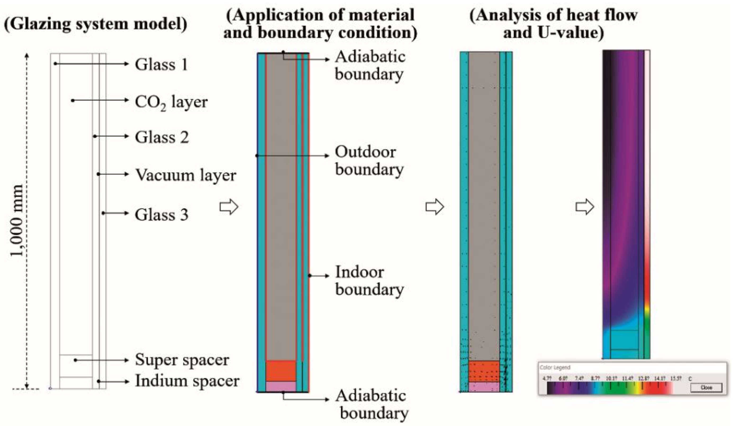
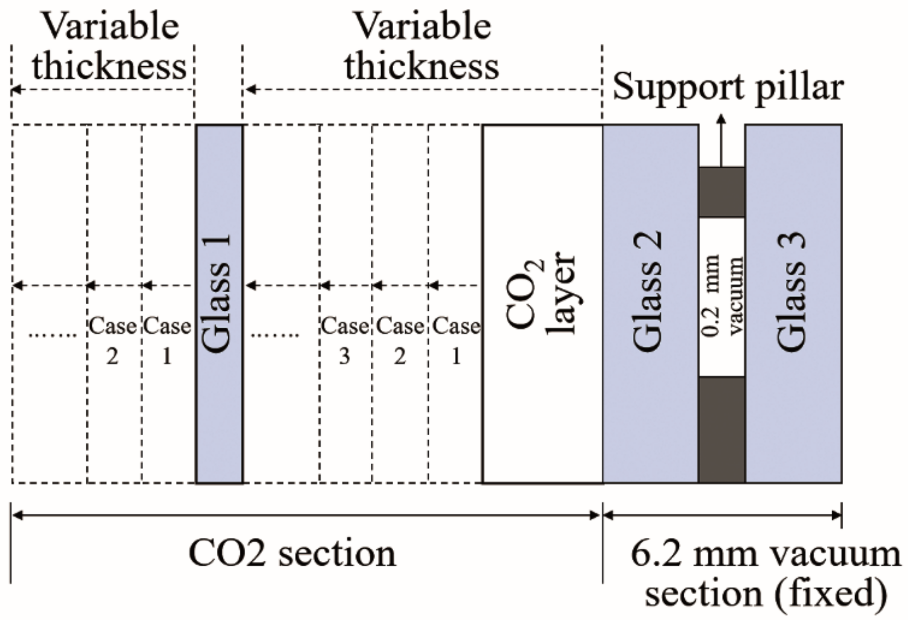
To calculate the optimal thickness and U-value of the proposed hybrid triple glazing system shown in Figure 3, the glazing was simulated using the materials described above in the Therm & Window program. For the design process, the program provides 'import' and 'underlay' functions to import DXF files created by 3D programs and to apply the exact size and thickness of the glazing, respectively [28]. Using these functions, the hybrid triple glazing system was first modeled by a CAD program. Then, the program was input as a DXF file in the Therm & Window program. The materials and characteristics of the glass, gas gap, and edge sealing were then input. Subsequently, the environmental conditions for the indoor and outdoor glass surfaces were input, as indicated in Table 7. The outdoor air temperature, wind speed, convection heat transfer coefficient, and solar radiation data were derived from 'standard weather data' and 'Korea standard' [35,36]. After setting the environmental conditions, the U-values of the edge and center portions of the glazing were calculated. In the simulation, the thickness of the vacuum section was 6.2 mm, including two sheets of 3-mm-thick glass and a 0.2-mm-thick vacuum gap. To determine the optimal thickness of the CO2 section, shown in Figure 4, the thickness of the CO2 gap and glass was increased by 1 mm, and the U-value of each case was calculated.
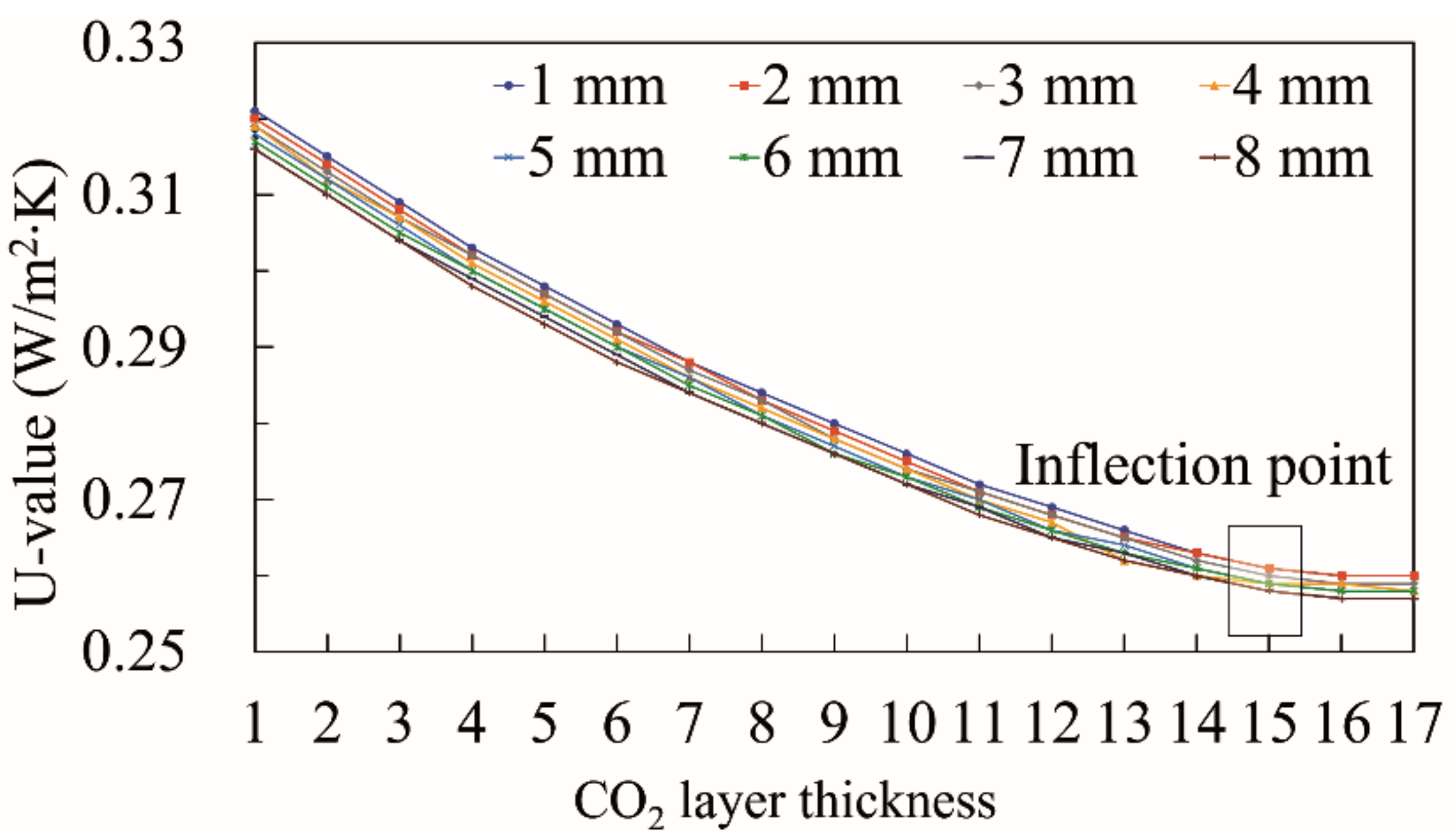
Figure 5 shows that, for all glass thicknesses (1–8 mm), the U-value decreased rapidly as the CO2 gap thickness was increased in 1-mm increments. However, when the thickness of the CO2 gap reached 15 mm, the U-value began to decrease at a lower rate. When the thickness of the CO2 gap was increased to more than 16 mm, there was almost no decrease in U-value for all glass thicknesses. Therefore, 15 mm was determined as the optimum thickness for the CO2 gap.
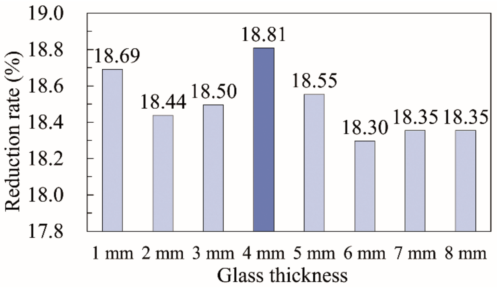
Figure 6 shows the rate of reduction in the U-value for each glass thickness due to increasing the thickness of the CO2 gap in the CO2 section from 1 to 15 mm. For all glass thicknesses, when the thickness of the CO2 gap was increased from 1 to 15 mm, the reduction in U-value ranged from 18.30 to 18.81%. A 4-mm-thick glass resulted in the maximum U-value reduction rate of 18.81%. Therefore, the optimum thickness of glass in the CO2 section with a 15-mm-thick CO2 gap was 4 mm. Consequently, the thickness of the vacuum section was 6.2 mm and that of the CO2 section was 19 mm, including a 15-mm-thick CO2 gap and a 4-mm-thick glass layer (Figure 7). The total thickness of the glazing was 25.2 mm, and the corresponding U-value was 0.259 W/m2·K.
2.5. Application of Glazing System to a Building
To analyze the energy performance of the proposed hybrid triple glazing system, it was applied to EnergyPlus, a building environment, and energy analysis program. Although it is preferable to compare the energy performance of the proposed glazing system with the eight glazing systems proposed in previous studies, the EnergyPlus provides solely components and logic for vacuum glazing and glazing with insulation gas. Thus, the other glazing types cannot be modeled using EnergyPlus [31]. Therefore, three typical insulation gases (air, Ar, and Kr) were utilized to compare the energy performance of the proposed system. The energy loss from the glazing and the total energy consumption of the building were analyzed for different glazing insulation gases in a building with the same envelope, indoor and outdoor conditions, and glazing structure. The simulation was performed during the winter heating period, which is characterized by large differences between indoor and outdoor temperatures.
2.5.1. Building Structure
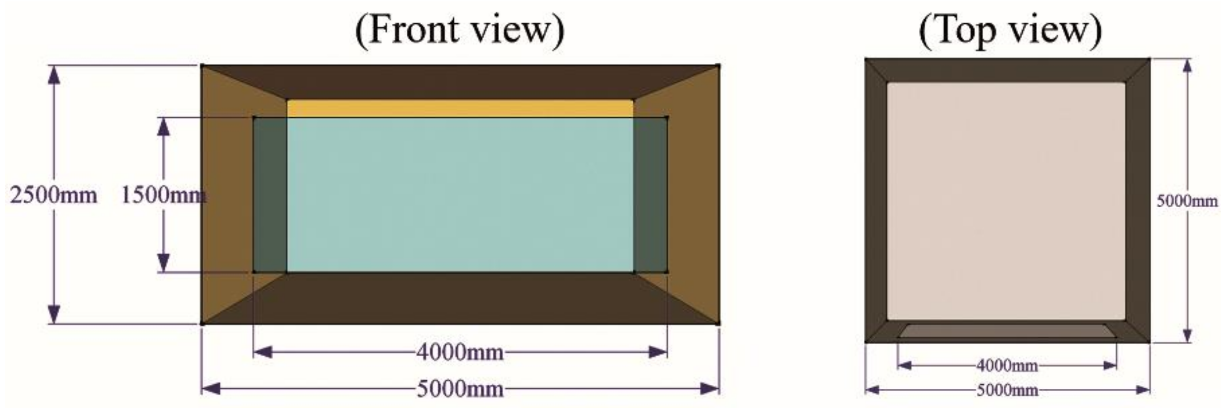
Figure 8 shows the front and top views of the building modeled by EnergyPlus. The width, depth, and height of the building were 5, 5, and 2.5 m, respectively. Glazing with a width of 4 m and a height of 1.5 m was installed on the south side of the building. Table 8 indicates that the location of the building was in Seoul, Korea, and “Seoul standard weather data” distributed by government agencies were used [36]. The period from December 1 to 10—the coldest days of the year—was simulated. Table 9 lists the structural and thermal characteristics of the building envelope. The building was constructed of concrete, and each envelope was designed to satisfy the domestic U-value criteria [37].
2.5.2. Outdoor Conditions
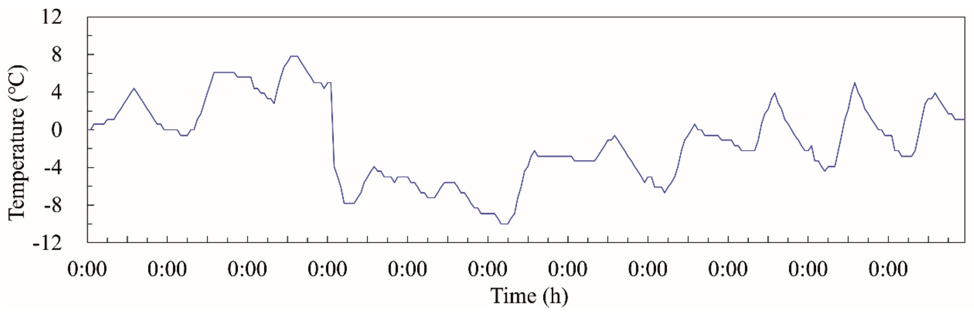
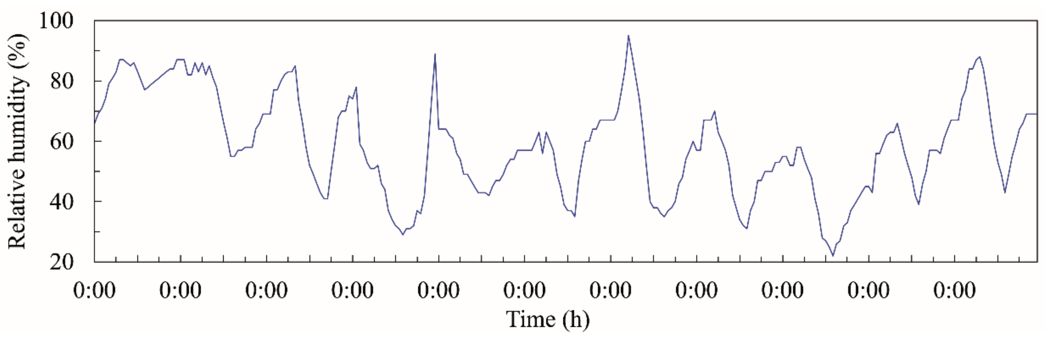
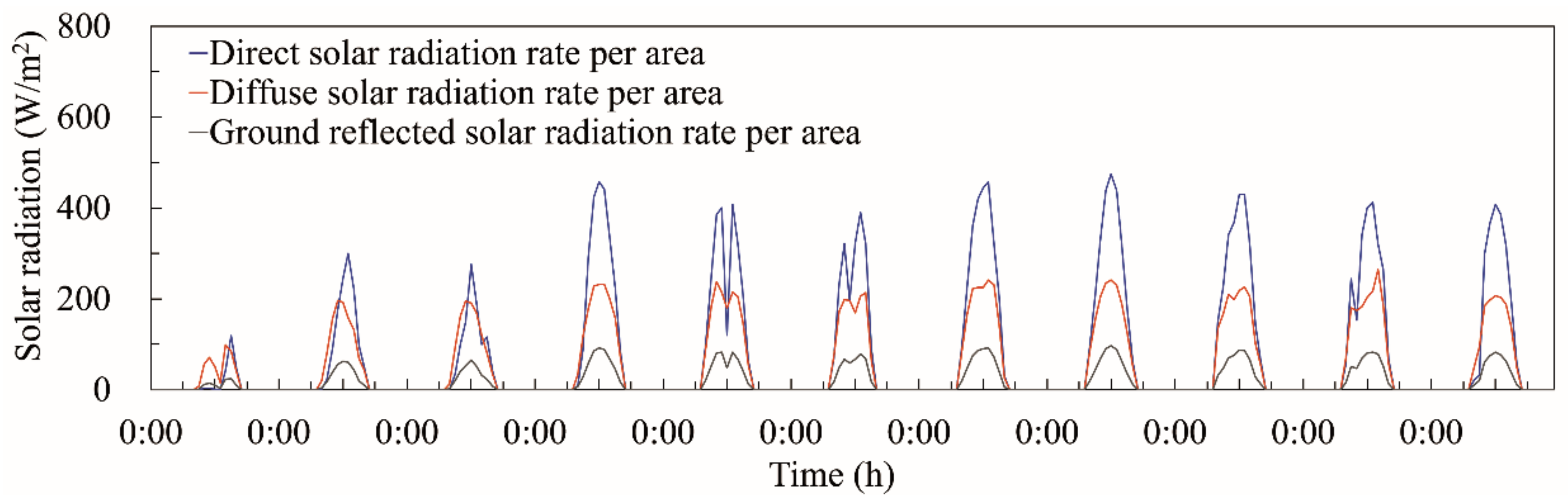
The analysis was conducted for approximately 10 days from 0:00 on December 1 to 0:00 on December 11. As the Seoul weather data were entered according to the time for each factor, the EnergyPlus results were also output as hourly data. Figure 9, Figure 10 and Figure 11 show the outdoor air temperature, relative humidity, and solar radiation data applied to the simulation program.
2.5.3. Indoor Conditions
Among the indoor conditions, the number of occupants, lighting, infiltration, and ventilation were applied as heat loss and gain factors. Table 10 lists the hourly schedule of each factor. Four occupants were present in the room from 18:00 to 08:00 the next day. There were no occupants from 08:00 to 18:00. The lighting was input as a ratio. The maximum activity period for the occupants was considered to be between 06:00 and 08:00, and 18:00 and 22:00, and a maximum ratio of 1 was entered. From 22:00 to 06:00 the following day was considered the sleeping period. Thus, the lowest lighting value of 0.1 was applied. For infiltration and ventilation, domestic standard values were employed, i.e., 1.0 and 0.5 air changes per hour, respectively. The value of ventilation was set as zero for 08:00 to 18:00 because there were no occupants [37,38,39,40]. The indoor temperature was set to 22 °C from 18:00 to 08:00 the next day, when occupants were present, and to 10 °C or above from 08:00 to 18:00, which were classified as non-heating hours. Table 11 also lists the characteristics of the indoor heating, ventilation, and air-conditioning (HVAC) system. The method used for indoor heating and cooling was the all-air method. According to the abovementioned conditions, the indoor set temperature was 22 °C, and the cooling set temperature was 25 °C. The heating and cooling capacities were not limited and were set to be automatically controlled by the simulation.
3. Results and Discussion
To evaluate the energy performance of the hybrid triple glazing system with vacuum and CO2 gaps, the virtual building was modeled using EnergyPlus. Furthermore, the energy performance of the building was compared when the CO2 gas was replaced with air, Ar, and Kr gas for the same vacuum and CO2 section structures. The analysis factors were as follows: (1) The surface temperature of the indoor glass side of the glazing, (2) the energy loss from the glazing, and (3) the total heating energy consumption of the building over the simulation period.
3.1. Indoor Temperature and Control
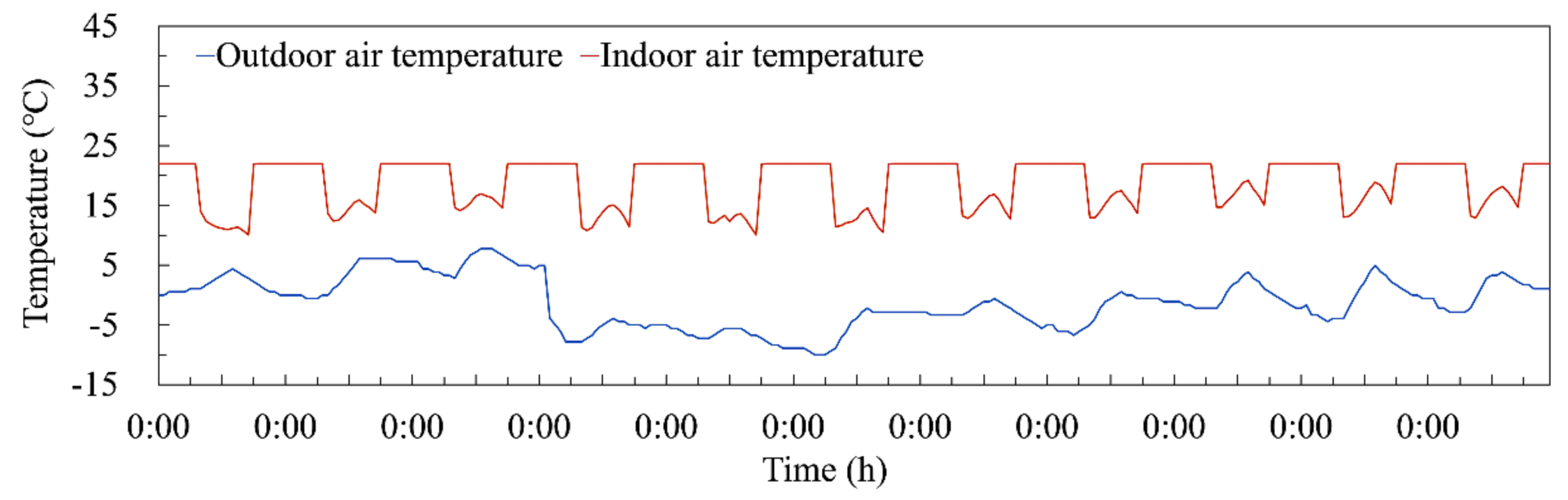
Before analyzing the energy performance, it was verified that the indoor temperature was effectively controlled under the set conditions. Figure 12 shows the hourly indoor temperature distribution with a change in outdoor temperature from 0:00 on December 1 to 0:00 on December 11. The temperature was set to 22 °C for indoor heating, and to 10 °C for non-heating hours. The simulation results corroborate that the indoor temperature was maintained at the set temperature of 22 °C from 18:00 to 08:00 the next day for all 10 days in the period, and the indoor temperature from 08:00 to 18:00 was maintained at 10 °C or above.
3.2. Surface Temperature of the Indoor Glazing Glass
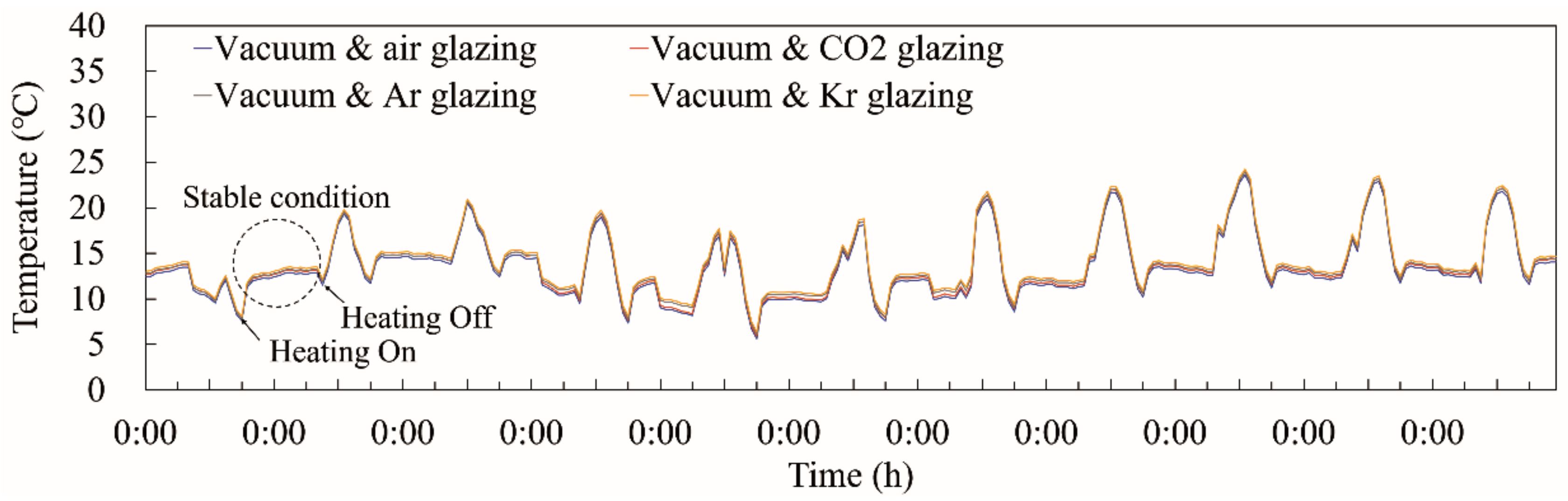
During the heating process, heat energy supplied to the indoor area through the HVAC system is lost to the outside sequentially from the indoor space, to the indoor surface of the glass, to the insulating gas, and finally to the outdoor surface of the glass. Among these, minimizing the heat energy loss between the indoor space (Inside in Figure 2) and the indoor glass surface of the glazing (Surface 1 in Figure 2) is key for reducing the total energy loss caused by the glazing. To this end, the temperature difference between the two sides should be minimized by increasing the indoor surface temperature of the glazing and lowering the indoor space temperature. However, as the indoor set temperature remains almost constant during the heating period, maintaining a high indoor surface temperature of the glazing, which is the only variable, is the best way to minimize the heat energy loss by reducing the temperature difference between the indoor space and the glass surface. In this case, the temperature of the indoor glass surface during the heating period depends on the influence of the cold outdoor environment. In other words, the effect of the outdoor environment on the indoor glass surface must be minimized. This is where the insulation performance of the gas gap plays an extremely important role. Better insulation performance of the gas gap in the glazing during the heating period allows for a higher indoor surface temperature of the glazing to be maintained. Therefore, the surface temperature of the indoor glass was analyzed for each glazing, i.e., with injection of either CO2, air, Ar, or Kr gas (Figure 13), to predict the energy performance of the entire glazing system.
During the simulation period, the surface temperature of the indoor glass ranged from 6 to 15 °C for the four different gases injected into the hybrid triple glazing during the heating period. The glazing with Kr gas maintained the highest surface temperature, whereas the glazing injected with air exhibited the lowest surface temperature. In addition, the surface temperature of the glazing injected with CO2 gas ranged between that of the glazing with Kr and air, and it was almost the same as that of the glazing injected with Ar gas. Note that the increases in glass surface temperature during the non-heating period are due to the absorption of solar radiation during daytime.
3.3. Energy Loss from Glazing
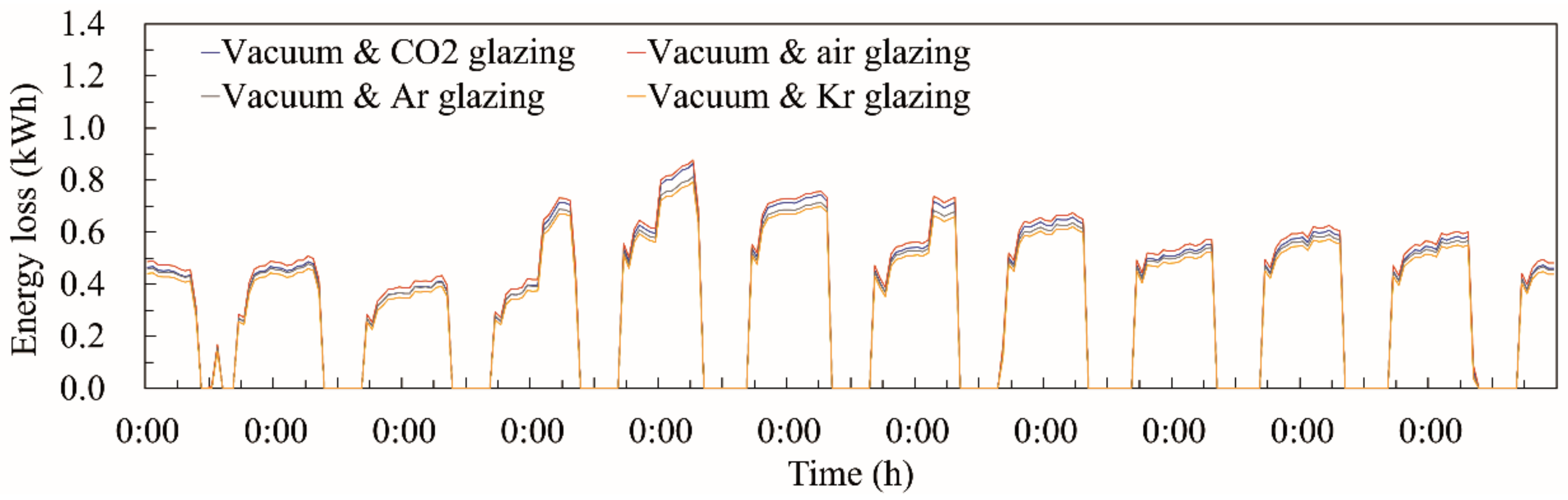
Figure 14 shows the hourly energy loss from the hybrid triple glazing system with CO2, air, Ar, and Kr gas during the simulation period. As mentioned previously, the surface temperature of the indoor glass was highest in the glazing with Kr gas and lowest for the glazing with air. Therefore, the glazing systems with Kr and air were expected to exhibit the smallest and largest energy loss, respectively. As expected, this result was observed in the actual simulation. The loss of heat energy from the hybrid triple glazing system including CO2 was slightly higher than or similar to that of the glazing with Ar gas.
3.4. Heating Energy Consumption of Building
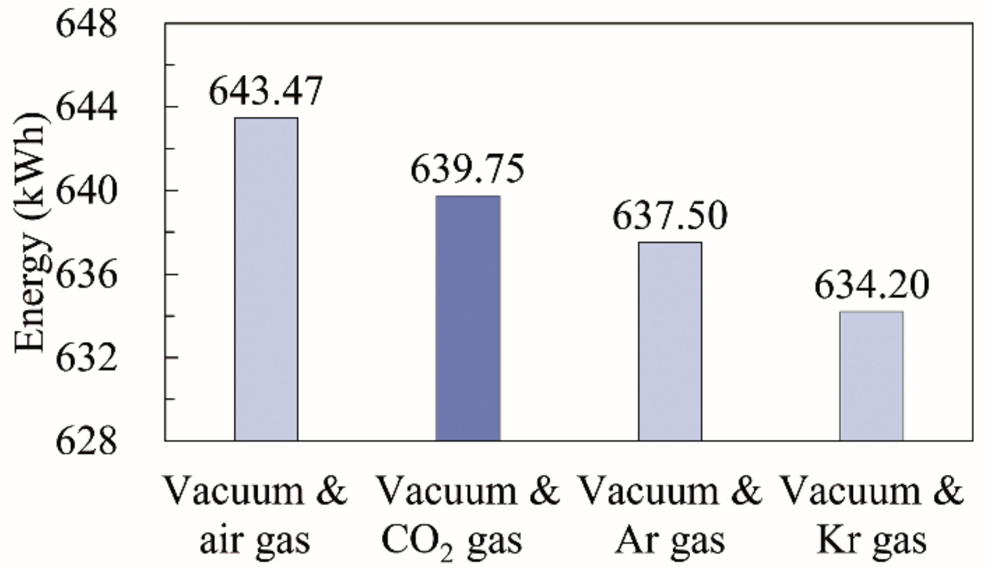
Figure 15 compares the total heating energy consumed in the building with hybrid triple glazing injected with CO2, air, Ar, and Kr gas during the 10-day simulation period. First, the building with Kr-glazing consumed the least amount of heating energy at 634.2 kWh. The heating energy consumption in buildings with Ar, CO2, and air glazing was 637.5, 639.75, and 643.47 kWh, respectively. Therefore, the energy performance of the proposed hybrid triple glazing with vacuum and CO2 gaps was slightly lower or approximately similar to that of glazing with a vacuum gap and air or Ar.
3.5. Research Limitations and Future Plans
According to the comparison of the energy performance of CO2, air, Ar, and Kr-based hybrid triple glazing systems, the vacuum and CO2 gap combination exhibited extremely similar energy performance to glazing systems combining vacuum and Ar gas. Previous studies have indicated that CO2 gas is expected to replace Ar gas, which has previously been widely used in glazing [25]. However, although the U-value of the proposed glazing system is superior to that of suspended, electrochromic, PCM, PV, self-cleaning, and aerogel glazing systems proposed in previous studies, it is slightly higher than the U-value of triple vacuum glazing. The performance limitations of the simulation program did not allow a direct comparison of their energy performance in real buildings. Nonetheless, EnergyPlus is constantly updating its glazing model components, as well as those of other energy-saving systems. Therefore, the future addition of components related to advanced glazing systems will enable a full comparison of their energy performance. In addition, comprehensive performance tests of the proposed glazing technology are planned for future research, as well as evaluations of actual prototypes using the domestic window test standard values for insulation, airtightness, water tightness, condensation, and internal wind pressure [35].
4. Conclusions
This paper proposed a hybrid triple glazing system combining vacuum and CO2 gaps to utilize CO2 gas as a resource in buildings. This initial study analyzed the optimum thickness and energy performance of the proposed glazing system. The conclusions of this study are as follows.
- (1).
- CO2 is a greenhouse gas and its use is strictly controlled both domestically and internationally. However, as CCS and CCU technologies are gaining increasing attention, it is now possible to utilize CO2 as a resource. This is done by processing the collected greenhouse gases. The glazing of windows will be practically the only factor for using pure CO2 gas as a resource in buildings. Because glazing requires an adiabatic gas and an edge sealing technology that seals the gas gap, there is a slight risk of the CO2 gas injected into the glazing being released into the atmosphere.
- (2).
- If CO2 gas is used in building glazing, the following three advantages are observed. First, as in our previous study, CO2 gas in glazing has very similar insulation performance as that of Ar gas. Thus, the price of glazing can be lowered by replacing existing, expensive Ar gas with cheap CO2 gas. Second, similar to forests, buildings can function as CO2/greenhouse gas absorbers. Third, it can help reduce CO2 treatment costs.
- (3).
- Recent research trends in glazing have focused on the development of super-insulated glazing with extremely low U-values. However, by using only CO2 gas and two sheets of glass, the U-value of glazing to the zero-point level required for super-insulated glazing can be reduced. Therefore, hybrid triple glazing with vacuum and CO2 sections was designed by introducing vacuum glazing developed from existing studies for the super-insulated performance of glazing using CO2 gas.
- (4).
- The optimum thickness of the proposed hybrid triple glazing was determined using the Therm & Window program, and the U-value was calculated. The thickness of the vacuum section was applied to a total thickness of 6.2 mm, following the results of previous studies. Meanwhile, the thickness of the CO2 section was determined by analyzing the change and decrease rate in U-value by increasing the thickness of the CO2 gap and glass by 1 mm. Therefore, the optimal thicknesses of the CO2 gap and glass were analyzed to be 15 and 4 mm, respectively. Therefore, total thickness of the proposed hybrid triple glazing, including both the vacuum and CO2 sections, is most suitable at 25.2 mm with a corresponding U-value of 0.259 W/m2·K.
- (5).
- The energy performance of the hybrid triple glazing was analyzed using the EnergyPlus program. It was necessary to compare the performance gaps between the proposed and advanced glazing presented in previous studies. However, owing to the limitations of the simulation program, the conventional insulation gas, air, Ar, and Kr gas were used as alternatives. The thickness of the glazing was maintained. However, the CO2 gas was changed to air, Ar, and Kr gas, and the energy consumption of the building was analyzed. Therefore, the energy performance of the hybrid triple glazing with vacuum and a CO2 gap was analyzed to be extremely similar to that of vacuum and Ar gas.
- (6).
- Given the limitations of the study, it was essential to compare the proposed glazing performance with those of advanced glazing proposed in previous studies. However, owing to the limitations of the program, it is currently impossible to conduct the comparative analysis. However, as in the calculation results of U-value, the hybrid triple glazing with vacuum and a CO2 gap exhibited a considerably better U-value than multi-layer, electrochromic, self-cleaning, PCM, and PV glazing, and values extremely close to the U-values of the triple vacuum and suspended glazing. Suspended glazing is the latest type of glazing developed and has received considerable interest. Therefore, it is thought that the proposed glazing could be utilized as next-generation glazing to absorb greenhouse gases in buildings and reduce energy consumption.
Author Contributions
Funding acquisition, S.B. and S.K.; project administration, S.B. and S.K.; supervision, S.K.; data curation, S.B.; formal analysis, S.B.; methodology, S.B.; resources, S.B.; software, S.B.; writing—original draft, S.B.; writing—review & editing, S.B. and S.K.
Funding
This research was funded by the Basic Science Research Program through the National Research Foundation of Korea (NRF) funded by the Ministry of Education (grant number: 2018R1D1A1B07048848).
Conflicts of Interest
The authors declare no conflict of interest.
References
- Erdem, C.; Saffa, B.R. A state-of-the art review on innovative glazing technologies. Renew. Sustain. Energy Rev. 2015, 41, 695–714. [Google Scholar] [CrossRef]
- Jelle, B.P.; Hynd, A.; Gustavsen, A.; Arasteh, D.; Goudey, H.; Hart, R. Fenestration of today and tomorrow: A state-of-the-art review and future research opportunities. Sol. Energy Mater. Sol. Cells 2012, 96, 1–28. [Google Scholar] [CrossRef] [Green Version]
- Hee, W.J.; Alghoul, M.A.; Bakhtyar, B.; OmKalthum, E.; Shameri, M.A.; Alrubaih, M.S.; Sopian, K. The role of window glazing on daylighting and energy saving in buildings. Renew. Sustain. Energy Rev. 2015, 42, 323–343. [Google Scholar] [CrossRef]
- Yueping, F.; Trevor, H.; Neil, H.; Philip, C.E.; Brian, N. Comparison of vacuum glazing thermal performance predicted using two-and three-dimensional models and their experimental validation. Sol. Energy Mater. Sol. Cells 2009, 93, 1492–1498. [Google Scholar] [CrossRef]
- Yueping, F.; Trevor, J.H.; Neil, H. Predicted thermal performance of triple vacuum glazing. Sol. Energy 2010, 84, 2132–2139. [Google Scholar] [CrossRef]
- Aritra, G.; Brian, N. Durability of switching behaviour after outdoor exposure for a suspended particle device switchable glazing. Sol. Energy Mater. Sol. Cells 2017, 163, 178–184. [Google Scholar] [CrossRef] [Green Version]
- Qi, L.; Yipin, W.; Jinyuan, Y.; Guifu, G. Impact resistance and static strength analysis of an extremely simplified micro hotplate with novel suspended film. Sens. Actuators A Phys. 2018, 208, 495–504. [Google Scholar] [CrossRef]
- Piccolo, A.; Pennisi, A.; Simone, F. Daylighting performance of an electrochromic window in a small scale test-cell. Sol. Energy 2009, 83, 832–844. [Google Scholar] [CrossRef]
- Piccolo, A.; Simone, F. Effect of switchable glazing on discomfort glare from windows. Build. Environ. 2009, 44, 1171–1180. [Google Scholar] [CrossRef]
- Ruben, B.; Bjorn, P.J.; Arild, G. Properties, requirements and possibilities of smart windows for dynamic daylight and solar energy control in buildings: A state-of-the-art review. Sol. Energy Mater. Sol. Cells 2010, 94, 87–105. [Google Scholar] [CrossRef] [Green Version]
- Baek, S.; Kim, S. Determination of optimaum hot-water temperatures for PCM radiant floor-heating systems based on the wet construction method. Sustainability 2018, 10, 4004. [Google Scholar] [CrossRef]
- IsmailJ, K.A.R.; Henriquez, R. Thermally effective windows with moving phase change material curtains. Appl. Therm. Eng. 2001, 21, 1909–1923. [Google Scholar] [CrossRef]
- Mohammed, M.F.; Amar, M.K.; Siddique, A.K.R.; Said, A.H. A review on phase change energy storage: Materials and applications. Energy Convers. Manag. 2004, 45, 1597–1615. [Google Scholar] [CrossRef]
- Tady, Y.Y.F.; Yang, H. Study on thermal performance of semi-transparent building-integrated photovoltaic glazings. Energy Build. 2008, 40, 341–350. [Google Scholar] [CrossRef]
- Henrik, D.; Bengt, P.; Bjorn, K. System analysis of a multifunctional PV/T hybrid solar window. Sol. Energy 2012, 86, 903–910. [Google Scholar] [CrossRef]
- Erdem, C.; Pinar, M.C. Effects of concavity level on heat loss, effectiveness and efficiency of a longitudinal fin exposed to natural convection and radiation. Int. J. Numer. Methods Heat Fluid Flow 2013, 23, 1169–1178. [Google Scholar] [CrossRef]
- Akira, F.; Xintong, Z. Titanium dioxide photocatalysis: Present situation and future approaches. Comptes Rendus Chim. 2006, 9, 750–760. [Google Scholar] [CrossRef]
- Raquel, P.; Garikoitz, B.; Arrate, M.; Josu, G.; Ana, A. Development of multifunctional sol–gel coatings: Anti-Reflection coatings with enhanced self-cleaning capacity. Sol. Energy Mater. Sol. Cells 2010, 94, 1081–1088. [Google Scholar] [CrossRef]
- Krister, M.; Bjorn, P.J. Self-cleaning glazing products: A state-of-the-art review and future research pathways. Sol. Energy Mater. Sol. Cells 2013, 109, 126–141. [Google Scholar] [CrossRef] [Green Version]
- Erdem, C.; Pinar, M.C.; Christopher, J.W.; Saffa, B.R. Optimizing insulation thickness and analysing environmental impacts of aerogel-based thermal superinsulation in buildings. Energy Build. 2014, 77, 28–39. [Google Scholar] [CrossRef]
- Erdem, C.; Pinar, M.C.; Christopher, J.W.; Saffa, B.R. Toward aerogel based thermal superinsulation in buildings: A comprehensive review. Renew. Sustain. Energy Rev. 2014, 34, 273–299. [Google Scholar] [CrossRef]
- Mar, P.F.; Andrei, B.D.; Evangelos, T. CO2 utilization pathways: Techno-economic assessment and market opportunities. Energy Procedia 2014, 63, 7968–7975. [Google Scholar] [CrossRef]
- Sara, B.; Samuel, K.; Niall, M.D.; Nigel, B.; Adam, H. An assessment of CCS costs, barriers and potential. Energy Strateg. Rev. 2018, 22, 61–81. [Google Scholar] [CrossRef]
- Bae, J.; Seo, H.; Ahn, E.; Lee, J. Patent trend analysis of carbon capture/storage/utilization technology. Korean Soc. Econ. Environ. Geol. 2017, 50, 389–400. [Google Scholar] [CrossRef]
- Baek, S.; Park, J.C. Analysis on thermal performance of double-pane unit filled carbon dioxide. Soc. Air Cond. Refrig. Eng. Korea 2015, 2015, 220–223. [Google Scholar]
- Manz, H.; Menti, U.P. Energy performance of glazings in European climates. Renew. Energy 2012, 37, 226–232. [Google Scholar] [CrossRef]
- Kassai, M.; Ge, G.; Simonson, C.J. Dehumidification performance investigation of run-around membrane energy exchanger system. Therm. Sci. 2016, 20, 1927–1938. [Google Scholar] [CrossRef]
- National Fenestration Rating Council. Therm 7/Window7 NFRC Simulation Manual. 2017. Available online: https://windows.lbl.gov/sites/default/files/Downloads/NFRCSim7-July2017.pdf (accessed on 4 September 2019).
- Carli Inc. Conrad 5 & Viewer 5 Technical and Programming Documentation. 2006. Available online: https://windows.lbl.gov/sites/all/files/Downloads/conrad-and-viewer-06-20-06.pdf (accessed on 4 September 2019).
- Kassai, M.; Simonson, C.J. Performance investigation of liquid-to-air membrane energy exchanger under low solution/air heat capacity rates ratio conditions. Build. Serv. Eng. Res. Technol. 2015, 36, 535–545. [Google Scholar] [CrossRef]
- U.S. Department of Energy. Input Output Reference. 2019. Available online: https://energyplus.net/sites/all/modules/custom/nrel_custom/pdfs/pdfs_v9.1.0/InputOutputReference.pdf (accessed on 4 September 2019).
- U.S. Department of Energy. Engineering Reference. 2019. Available online: https://energyplus.net/sites/all/modules/custom/nrel_custom/pdfs/pdfs_v9.1.0/EngineeringReference.pdf (accessed on 4 September 2019).
- Yueping, F.; Trevor, J.H.; Farid, A.; Neil, H.; Philip, C.E.; Brian, N.; Seth, M. Indium alloy-sealed vacuum glazing development and context. Renew. Sustain. Energy Rev. 2014, 37, 480–501. [Google Scholar] [CrossRef]
- Van Den Bergh, S.; Hart, R.; Petter Jelle, B.; Gustavsen, A. Window spacers and edge seals in insulating glass units: A state-of-the art review and future perspectives. Energy Build. 2013, 58, 263–280. [Google Scholar] [CrossRef]
- Korean Standard Service Network. Standard Test Method for Thermal Resistance for Windows and Doors. 2017. Available online: https://www.kssn.net/search/stddetail.do?itemNo=K001010113352 (accessed on 4 September 2019).
- Passive House Institute Korea. Republic of Korea Standard Weather Data. 2017. Available online: http://www.phiko.kr/bbs/board.php?bo_table=z3_01&wr_id=2479 (accessed on 4 September 2019).
- National Law Information Center. Building Energy Conservation Design Standards 2018. Available online: http://www.law.go.kr/admRulLsInfoP.do?admRulSeq=2100000106860 (accessed on 4 September 2019).
- Korean Institute of Architectural Sustainable Environment and Building System. Building Airtightness Criteria 2013. Available online: http://www.kiaebs.org/board/?_0000_method=view&ncode=a003&num=11&page=1 (accessed on 4 September 2019).
- Kassai, M. Experimental investigation of carbon dioxide cross-contamination in sorption energy recovery wheel in ventilation system. Build Serv. Eng. Res. Technol. 2018, 39, 463–474. [Google Scholar] [CrossRef]
- Ren, X.Y.Y.; Zhang, C.B.; Zhao, Y.; Boxem, G.; Zeiler, W.; Li, T.T. A data mining-based method for revealing occupant behavior patterns in using mechanical ventilation systems of Dutch dwellings. Energy Build. 2019, 193, 99–110. [Google Scholar] [CrossRef]
Figure 1.
Flow chart of this study.

Figure 2.
Structure of the hybrid triple glazing system with vacuum and CO2 gaps.

Figure 3.
Illustration of glazing simulation process by Therm & Window program.

Figure 4.
Simulation method for determining optimal thickness of CO2 section.

Figure 5.
Decrease in U-value of glass according to thickness of CO2 gap.

Figure 6.
Rate of reduction in U-value reduction caused by increasing CO2 gap thickness from 1 to 15 mm.
Figure 6.
Rate of reduction in U-value reduction caused by increasing CO2 gap thickness from 1 to 15 mm.

Figure 7.
Final design of hybrid triple glazing system.

Figure 8.
Schematic of virtual building designed by EnergyPlus.

Figure 9.
Hourly temperature data used in the simulation.

Figure 10.
Hourly relative humidity data used in the simulation.

Figure 11.
Hourly solar radiation data used in the simulation.

Figure 12.
Changes in room temperature during the simulation period.

Figure 13.
Surface temperature changes of the hybrid triple glazing with CO2, air, Ar, and Kr as the insulation gas.
Figure 13.
Surface temperature changes of the hybrid triple glazing with CO2, air, Ar, and Kr as the insulation gas.

Figure 14.
Heat energy loss from the hybrid triple glazing systems injected with CO2, air, Ar, and Kr.
Figure 14.
Heat energy loss from the hybrid triple glazing systems injected with CO2, air, Ar, and Kr.

Figure 15.
Heating energy consumption of buildings with hybrid triple glazing systems injected with CO2, air, Ar, and Kr.
Figure 15.
Heating energy consumption of buildings with hybrid triple glazing systems injected with CO2, air, Ar, and Kr.


| No. | Type of Glazing | Type of Gap | U-Value at Center (W/m2·K) |
|---|---|---|---|
| 1 | Multi-layer | Insulating gas | 0.70 |
| 2 | Triple vacuum | Vacuum with pillar (Double vacuum gap) | 0.24 |
| 3 | Suspended | Insulating gas with film | 0.28 |
| 4 | Electrochromic | Insulating gas with chromogenic material | 0.62 |
| 5 | PCM | Insulating gas with PCM | 0.50 |
| 6 | Photovoltaic | Insulating gas | 1.10 |
| 7 | Self-cleaning | Insulating gas | 1.20 |
| 8 | Aerogel | Aerogel | 0.40 |
Table 2.
Optical and thermal properties of glass used in vacuum and CO2 sections.
| Glass Name | SGG COOL-LITE XTREME 50-22 II | |||||||||
|---|---|---|---|---|---|---|---|---|---|---|
| Thickness | 3 mm | |||||||||
| Conductivity | 1.0 W/m·K | |||||||||
| Optical Characteristic | Total solar radiation | Visible rays | Emissivity | |||||||
| Tsol1 | Tsol2 | Rsol1 | Rsol2 | Tvis1 | Tvis2 | Rvis1 | Rvis2 | Emis1 | Emis2 | |
| 0.175 | 0.175 | 0.571 | 0.372 | 0.516 | 0.516 | 0.118 | 0.137 | 0.016 | 0.840 | |
| Tsol1 | Solar radiation ratio transmitted through the front surface of the glass (surface 1, 3, and 5 in Figure 3) | |||||||||
| Tsol2 | Solar radiation ratio transmitted through the back surface of the glass (surface 2, 4, and 6 in Figure 3) | |||||||||
| Rsol1 | Solar radiation ratio reflected through the front surface of the glass (surface 1, 3, and 5 in Figure 3) | |||||||||
| Rsol2 | Solar radiation ratio reflected through the back surface of the glass (surface 2, 4, and 6 in Figure 3) | |||||||||
| Tvis1 | Visible ray ratio transmitted through the front surface of the glass (surface 1, 3, and 5 in Figure 3) | |||||||||
| Tvis2: | Visible ray ratio transmitted through the back surface of the glass (surface 2, 4, and 6 in Figure 3) | |||||||||
| Rvis1 | Visible ray ratio reflected through the front surface of the glass (surface 1, 3, and 5 in Figure 3) | |||||||||
| Rvis2 | Visible ray ratio reflected through the back surface of the glass (surface 2, 4, and 6 in Figure 3) | |||||||||
| Emis1 | Surface emissivity through the front surface of the glass (surface 1, 3, and 5 in Figure 3) | |||||||||
| Emis2 | Surface emissivity in through the back surface of the glass (surface 2, 4, and 6 in Figure 3) | |||||||||
Table 3.
Physical and thermal characteristics of vacuum gap.
| Type | Mixed Vacuum-Air | |
|---|---|---|
| Thickness | 0.2 mm | |
| Molecular weight | 28.970 mol | |
| Pressure | 0.1332 Pa = 0.01 Torr | |
| Gap conductance | 0.106787 W/m2·K | |
| Support pillar | Type | Circular |
| Radius | 0.2 mm | |
| Spacing | 30 mm | |
Table 4.
Material and characteristics used for edge sealing of vacuum gap.
| Type | Material | Width (mm) | Hight (mm) | Conductivity (W/m·K) |
|---|---|---|---|---|
| Solid | Indium | 0.2 | 15 | 83.7 |
Table 5.
Physical and thermal properties of CO2 gas.
| Insulating Gas | Carbon Dioxide (CO2) | |
|---|---|---|
| Molecular Weight (mol/g) | 44.010 | |
| Pressure (Pa) | 101,325 | |
| Prandtl Number (Pr) | 0.7808 | |
| Conductivity coefficients | A (W/m·K) | 0.00037 |
| B (W/m·K2) | 0.00002954 | |
| C (W/m·K3) | 0.00000008 | |
| Viscosity coefficients | A (kg/m·s) | 0.00000116 |
| B (kg/m·s·K) | 0.00000006 | |
| C (kg/m·s·K2) | 0 | |
| Specific heat coefficients | A (J/kg·K) | 558.8 |
| B (J/kg·K2) | 1.04960001 | |
| C (J/kg·K3) | 0.00023876 | |
Table 6.
Materials and characteristics of the edge sealing for the CO2 gap.
| Type | Material | Hight (mm) | Conductivity (W/m·K) | |
|---|---|---|---|---|
| Solid | Primary sealing | Flexible EPDM* form (Including desiccant) | 15 | 0.18 |
| Secondary sealing | Polyisobutylene (PIB) | |||
* EPDM: Ethylene propylene diene monomer.
Table 7.
Indoor and outdoor environmental conditions for calculating U-value.
| Air Temperature | Wind Velocity | Convection Heat Transfer Coefficient | Solar Radiation | |
|---|---|---|---|---|
| (°C) | (m/s) | (W/m2·K) | (W/m2) | |
| Indoor | 20 | 1.2 | 9.1 | - |
| Outdoor | 0 | 4.2 | 21.2 | 558 |
Table 8.
Basic information on simulated building.
| Site Location | Seoul, South Korea | Latitude | 37.34 |
|---|---|---|---|
| Longitude | 126.57 | ||
| Building structure | Reinforced concrete | ||
| Size of building | Length 5 m × Width 5 m × Height 2.5 m | ||
| Direction of building | Corrected South | ||
| Size of window | 4 × 1.5 m | ||
| Weather data | Seoul standard weather data (EPW*) | ||
| Run period | From December 1 to December 10 (10 days) | ||
* EPW: EnergyPlus Weather data.
Table 9.
Structure and thermal characteristics of building envelopes.
| Structure | Type of Material | Thickness (m) | Conductivity (W/m·K) | Thermal Transmittance (W/m2·K) |
|---|---|---|---|---|
| Floor | Concrete slab | 0.21 | 1.4 | 0.178 (Domestic standard: 0.180) |
| Insulation | 0.17 | 0.034 | ||
| Autoclaved lightweight concrete | 0.04 | 0.15 | ||
| Finishing mortar | 0.04 | 0.72 | ||
| Finishing material | 0.005 | 0.16 | ||
| Wall | Concrete wall | 0.18 | 1.4 | 0.258 (Domestic standard: 0.260) |
| Insulation | 0.12 | 0.034 | ||
| Gypsum panel | 0.01 | 0.17 | ||
| Roof | Finishing mortar | 0.08 | 0.72 | 0.142 (Domestic standard: 0.150) |
| Concrete slab | 0.21 | 1.4 | ||
| Insulation | 0.09 | 0.035 | ||
| Air cavity | 0.1 | 0.025 | ||
| Gypsum panel | 0.01 | 0.17 |
Table 10.
Indoor environmental conditions and temperature control.
| Type of Input | Time Gap | Unit | Value |
|---|---|---|---|
| Occupant | 00:00–08:00 | Person | 4 |
| 08:00–18:00 | 0 | ||
| 18:00–00:00 | 4 | ||
| Light | 00:00–06:00 | Fraction (0 ≤ Light ≤ 1) | 0.1 |
| 06:00–08:00 | 1 | ||
| 08:00–18:00 | 0 | ||
| 18:00–22:00 | 1 | ||
| 22:00–00:00 | 0.1 | ||
| Infiltration | 00:00–24:00 | 1.0 air change per hour | 1 |
| Ventilation | 00:00–08:00 | 0.5 air change per hour | 0.5 |
| 08:00–18:00 | 0 | ||
| 18:00–00:00 | 0.5 | ||
| Heating Control | 00:00–08:00 | Temperature (°C) | 22 |
| 08:00–18:00 | 10 | ||
| 18:00–00:00 | 22 |
Table 11.
Characteristics of the indoor heating, ventilation, and air-conditioning (HVAC) system.
| Type | All-Air Method | |
|---|---|---|
| Indoor conditions | Heating set-point | 22 °C |
| Heating limit | No limit | |
| Cooling set-point | 25 °C | |
| Cooling limit | No limit | |
| Supply air | Maximum heating temperature | 50 °C |
| Maximum heating humidity | 0.0156 (kg/kg Dry air) | |
| Maximum cooling temperature | 10 °C | |
| Maximum cooling humidity | 0.0077 (kg/kg Dry air) | |
| Temperature control | Heating & cooling set-point | |
| Airflow rate control | Autosize | |
| Return air | Heat recovery type | Enthalpy |
| Sensible heat recovery rate | 0.9 | |
| Latent heat recovery rate | 0.9 | |
| Outdoor air | Outdoor air condition | Weather data |
| Flow rate control | Autosize | |
© 2019 by the authors. Licensee MDPI, Basel, Switzerland. This article is an open access article distributed under the terms and conditions of the Creative Commons Attribution (CC BY) license (http://creativecommons.org/licenses/by/4.0/).
Share and Cite
MDPI and ACS Style
Baek, S.; Kim, S. Optimum Design and Energy Performance of Hybrid Triple Glazing System with Vacuum and Carbon Dioxide Filled Gap. Sustainability 2019, 11, 5543. https://0-doi-org.brum.beds.ac.uk/10.3390/su11195543
AMA Style
Baek S, Kim S. Optimum Design and Energy Performance of Hybrid Triple Glazing System with Vacuum and Carbon Dioxide Filled Gap. Sustainability. 2019; 11(19):5543. https://0-doi-org.brum.beds.ac.uk/10.3390/su11195543
Chicago/Turabian StyleBaek, Sanghoon, and Sangchul Kim. 2019. "Optimum Design and Energy Performance of Hybrid Triple Glazing System with Vacuum and Carbon Dioxide Filled Gap" Sustainability 11, no. 19: 5543. https://0-doi-org.brum.beds.ac.uk/10.3390/su11195543
Note that from the first issue of 2016, this journal uses article numbers instead of page numbers. See further details here.