State of the Art of Techno-Economics of Nanofluid-Laden Flat-Plate Solar Collectors for Sustainable Accomplishment


Abstract
:1. Introduction
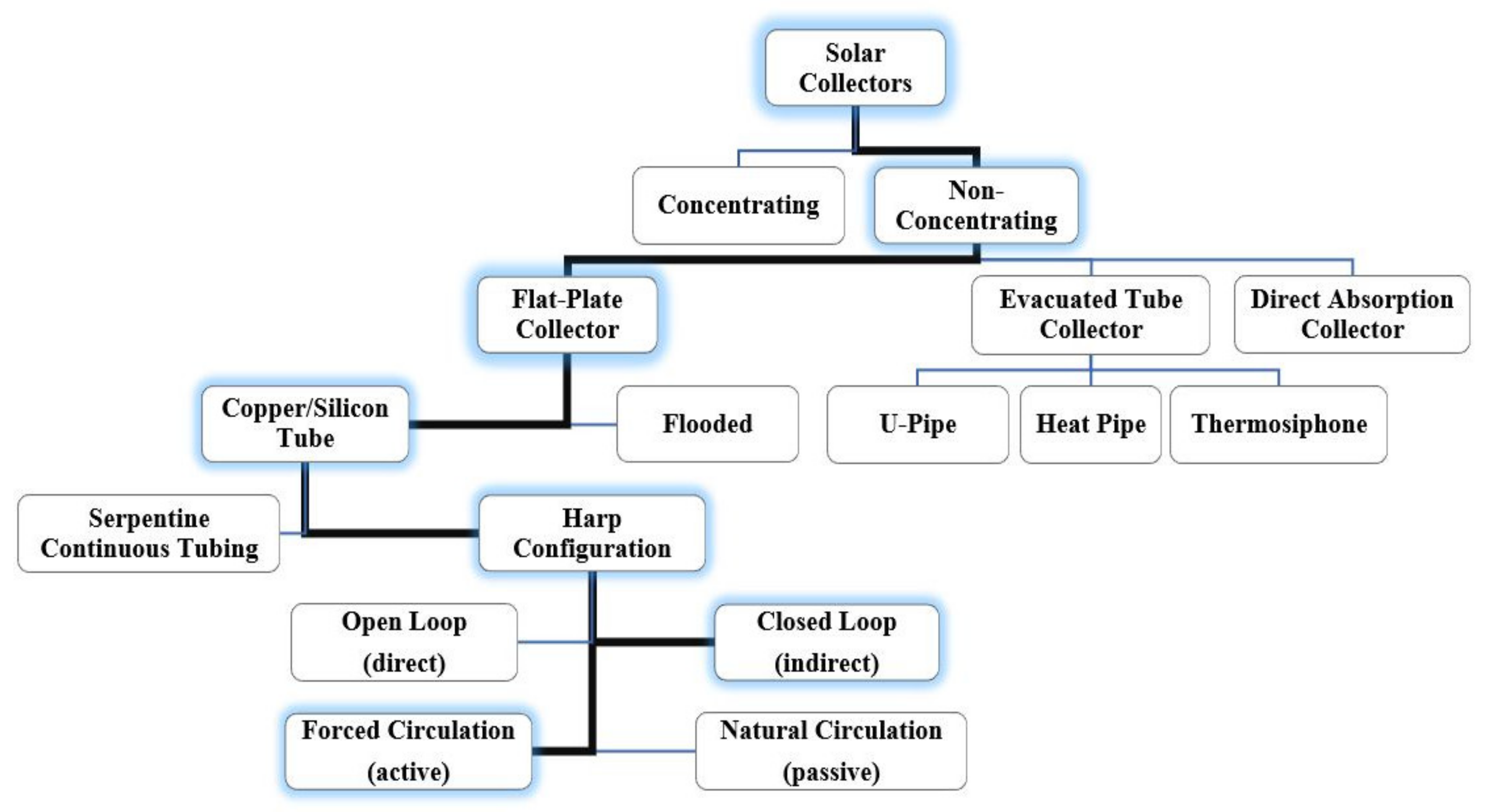
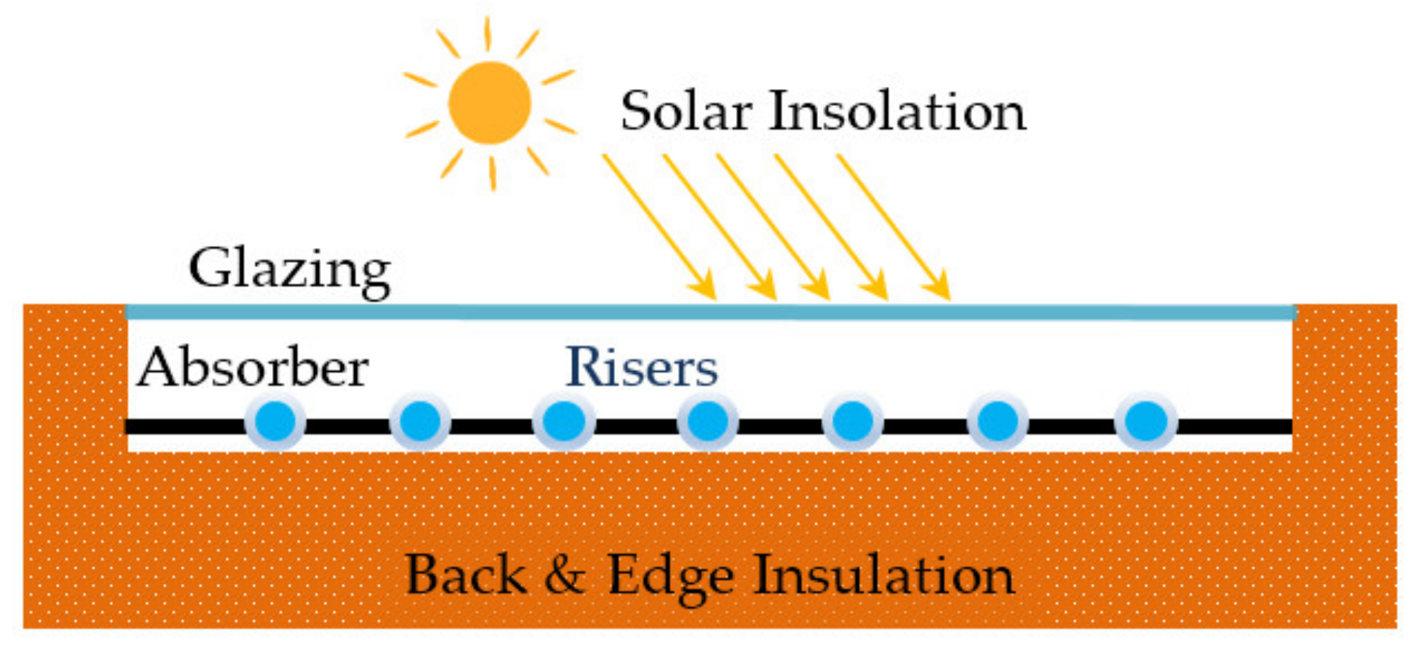
2. Solar Thermal Collectors for Water Heating
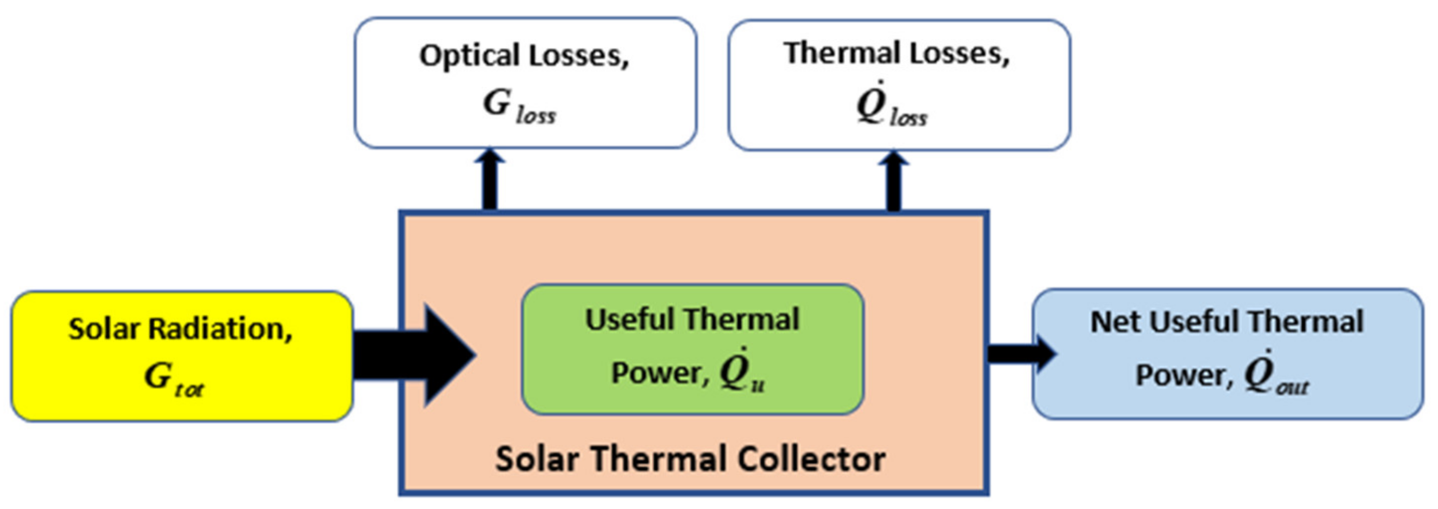
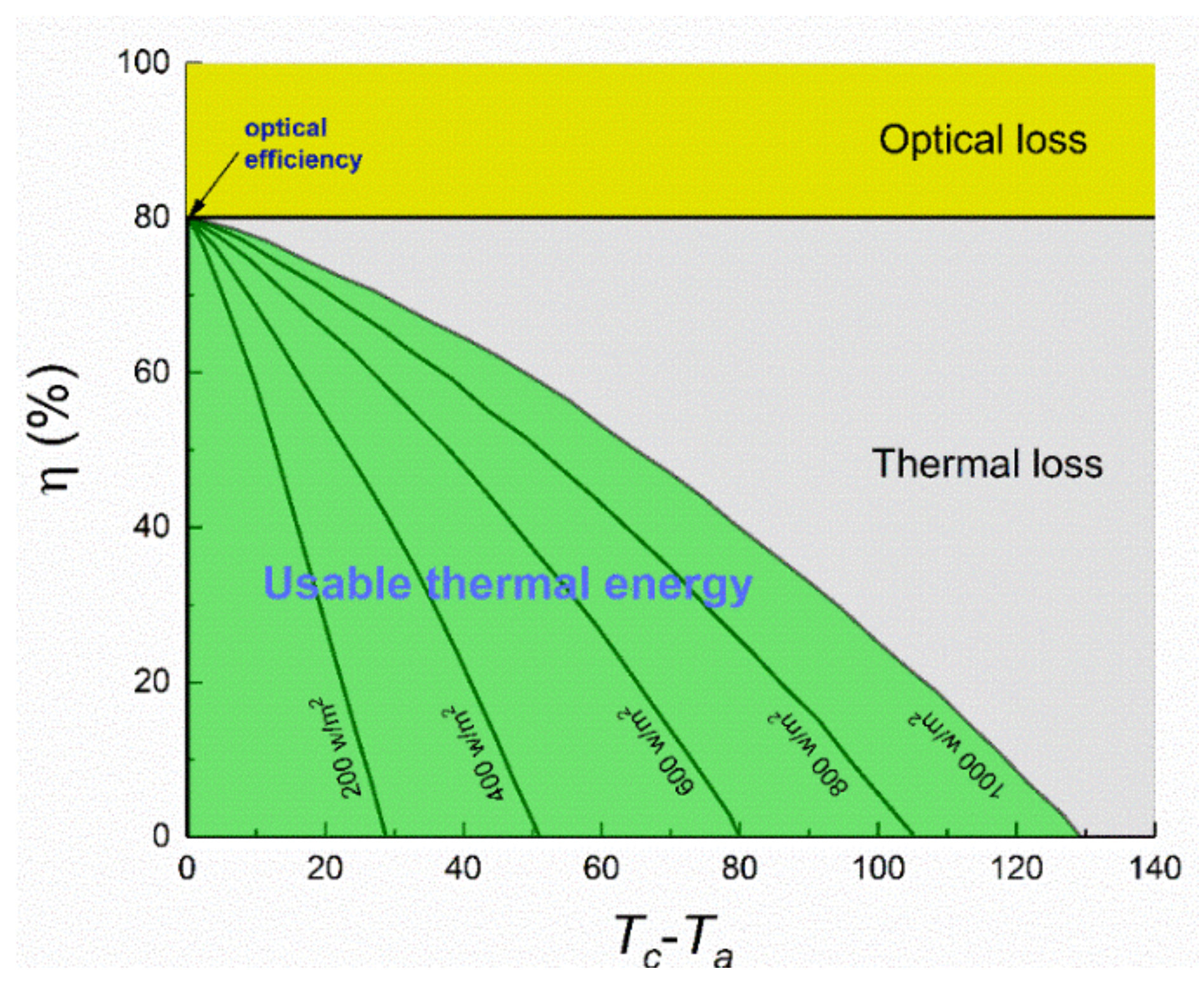
3. Energy Conversion in a Solar FPC
4. Nanotechnology and Nanomaterials for FPCs
4.1. Concept of Nanofluids
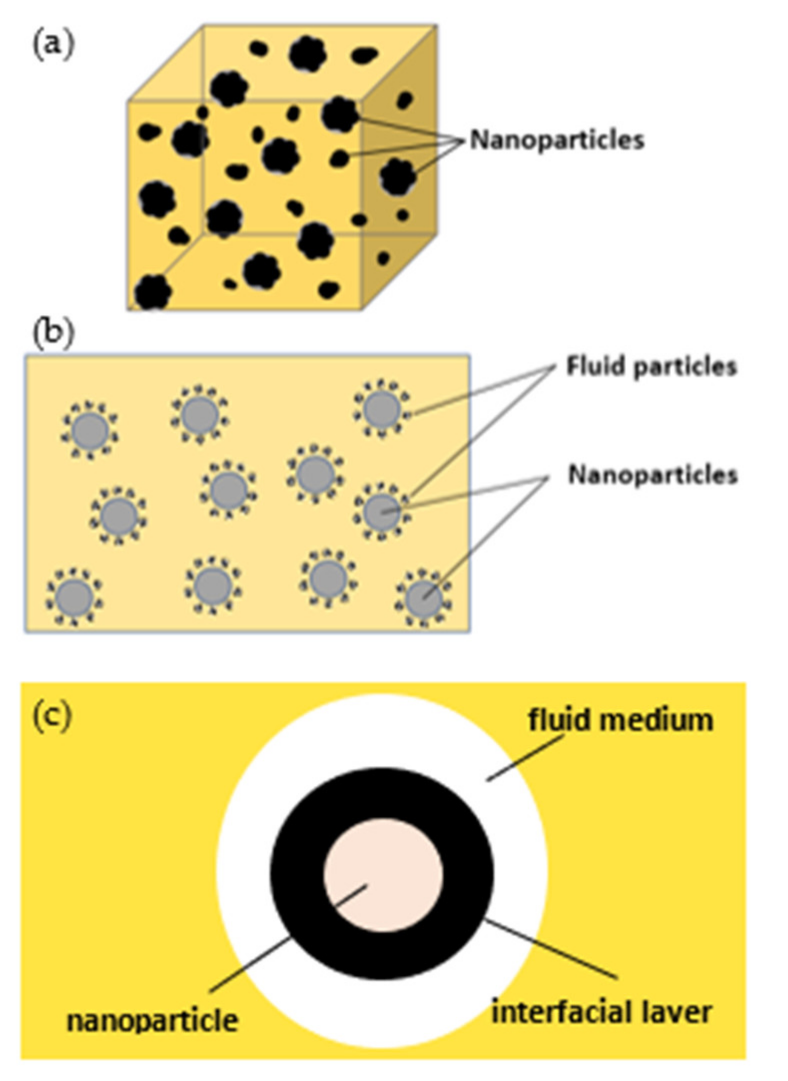
4.2. Definition of Nanofluid
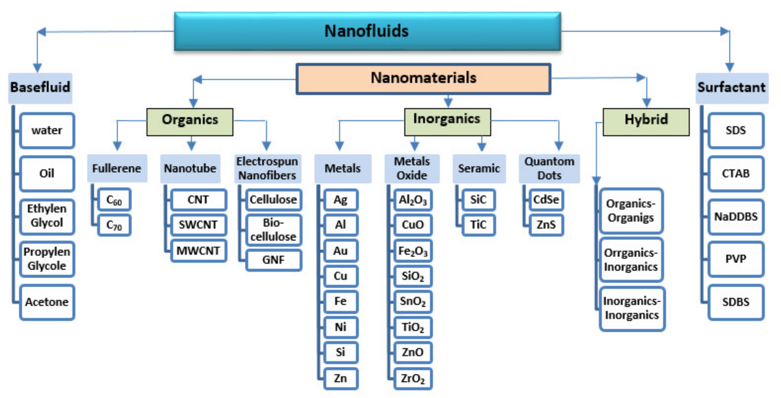
4.3. Classification of Nanofluid
- (1)
- Organic nanomaterials (fullerene, nanotube, electrospun),
- (2)
- Inorganic nanomaterials (metal, metal oxides, ceramics, quantum dots), and
- (3)
- Hybrid nanomaterials.
4.4. Preparation of Nanofluid
4.5. Concentration of Nanofluid
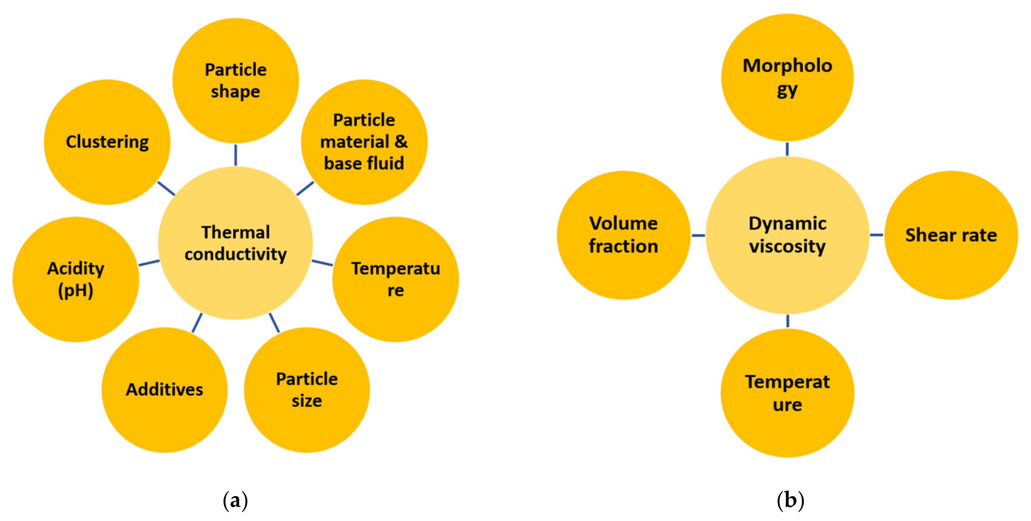
4.6. Thermophysical Properties of Nanofluids
4.6.1. Density Models of Nanofluids
4.6.2. Heat Capacity models of Nanofluids
4.6.3. Thermal Conductivity Models of Nanofluids
4.6.4. Viscosity Models of Nanofluids
4.7. Thermophysical Property Models of Base Fluids for FPCs
4.8. Heat Transfer Correlations of Nanofluid for FPCs
5. Thermal Efficiency of Nanofluid-Based FPCs
6. Exergy Efficiency of Nanofluid-Based FPCs
7. Economic Performance of Nanofluid-Based FPCs
8. Summary and Conclusions
- Some inconsistencies between the results of different studies have been observed, especially for pressure drop change with nanofluid working flow. Moreover, the linear friction losses in manifolds of FPCs are also important when estimating the performance of nanofluid-based FPCs and must be considered. A literature survey showed that the pressure drop in headers is overlooked in almost all studies on nanofluid-filled FPCs and should be considered.
- Most reported investigations analyzed the thermal energy enhancement for the zero-loss point at which the ambient temperature and collector inlet temperature are equal. This is very different from the nominal working conditions of a real solar FPC. In fact, it shows the conditions at which there is no thermal absorption and only the optical performance of the collector would be regarded. This is why the reported enhancements for thermal efficiency of nanofluid-based FPCs are so high. It is required in future investigations to evaluate the overall efficiency of the collector operating with nanofluid as the absorbing agent.
- All investigations carried out thus far for exergy balance of conventional and nanofluid-based FPCs have used the Carnot and PLP models for incident radiation exergy. It is realized, based on many research studies, that the apparent temperature of the sun is taken as 4500 K, while the valid quantity is 5770 K, or it is said to be 6000 K. It is less known that these models were developed for the case where the ambient consists of radiation emitted by a blackbody collector. Therefore, their usage is rigorously restricted to the case where the conversion of radiation energy into work is performed by using blackbody collectors. This fact may confront the exergy evaluation of FPCs, a conceptual challenge, since spectrally selective (not blackbody) absorbers are used in FPCs. Therefore, a more elaborated and precise exergy factor model should be adopted.
- Considering the mean temperature of 6000 K and 300 K for the sun and ambient air, respectively, the maximum exergy efficiency of an FPC cannot exceed 5%. Therefore, the exergy efficiencies that have been reported by some investigations need to be revisited.
- The combined application of selective absorbers and nanofluids for improving the power generation by FPCs has not been reported in the current literature. The key role of the ratio of the absorber plate’s emittance to its absorptance must be given attention, since only certain values are allowed by the second-law requirements.
- The absorber plate of a solar FPC is at the same time an emitter of the received radiation. The exergy loss due to the radiation emission by the absorber plate is also of importance to be discussed and considered.
- Regarding the fact that using nanofluids instead of water as HTF in conventional FPCs will affect all thermophysical properties including conductivity from one side and viscosity and density from the other side, a comprehensive techno-economic optimization is very crucial. This optimization should cover thermal efficiency, exergy efficiency, and economic performance of an FPC, which is going to be operated with a nanofluid working agent. Such a techno-economic optimization, called multi-objective optimization, for the performance of a nanofluid-charged FPC has not been reported yet by the current literature. Furthermore, very limited numbers of practical investigations with a standard and commercial SWH based on FPC have been reported.
- The existing correlations for evaluating the behavior of different nanofluids are not general and most of them are applicable for special conditions in terms of concentration and size of NPs. Therefore, still there exists a substantial need for development of a generalized model for the thermophysical properties of different common nanofluids. The stability of the nanofluids, especially at temperatures higher than 60 °C, remains a problem that has not been dealt with in carried-out investigations. It is not very easy to have stable nanofluids at volume concentrations higher than 1% in practice. In this regard, it should be noted that using surfactants will cause the conductivity of nanofluid to decrease. The stability problem would be critical for dense nanofluids, e.g., Cu and CuO nanoparticles. Therefore, selecting concentration ranges beyond 1.0% should be made with enough attention to the consequent issues.
- With regard to the importance of sustainable development, it is essential to use materials that are less chemically contained. In other words, it would be preferred to exploit bio-based materials to advance the renewable cycle as much as possible. However, it is inferred from the literature that ethylene glycol (EG), propylene glycol (PG), and polyethylene glycol (PEG) have been frequently used as base liquid mixtures with water. All of them are chemically-derived or even, like EG for instance, may have toxic effects on the environment. Any bio liquid for a mixture base fluid has been used for FPCs, while bio-glycol (BG), which is a renewable-derived product, possesses the capability to be investigated for this purpose. A comparative study on the effects of these products seems to be essential in future investigation in the field of nanofluid-based FPCs.
- In most of investigations, the specification of the FPC is not given. First, this can be a problem for the other researchers to repeat the study. Second, the important data like absorptivity and emissivity of the absorber plate should be known to assess its capability of work extraction. This would be very important when the subject matter is exergy analysis and work extraction of a nanofluid-based FPC. The assessment would be possible by using the existing equations and considering the ratio of these two properties.
- The models for estimating different parameters, specification of the selected nanoparticles, and flow regime under which the analysis has performed are not disclosed in some research works. The most important parameter for an FPC is the mass flux of working fluid, which is the amount of mass flow per unit surface area of the collector. The mass flux is usually recommended to be in a certain range with regard to the design features by the manufacture. The change in collector flow rate suggested by some research studies should be analyzed considering this range. Different mass fluxes from the design or nominal point might change the collector performance, e.g., the rate of heat transfer and pipe corrosion speed.
- Economic and environmental aspects that previously been studied have not covered the details of the application of nanofluids in FPCs. Adoption of nanofluid application in FPCs should be subjected to financial feasibility to evaluate the success of the investment. Not only the material costs should be considered, as the operating costs are vital parameters, as well in the feasibility analysis. For instance, since nanofluids are stable for only for a few months, they need to be changed at least three or four times per year. The running and operational costs should be considered in economic analysis, along with purchase or preparation costs, and the relevant payback period should be analyzed.
- Sustainable accomplishment can be enhanced or lessened depending on factor(s) of consideration. It may be evaluated by many factors on adoptability of the nano tech in flat-plate solar systems. These factors may be cost effectiveness, reduction in CO2 emission, and reduction of environmental harms.
- Adopting bio blended base fluid as thermal working fluid in FPCs is environmentally-friendly compared to the chemical product’s base fluids.
- The developed cost analysis method will provide a tool for the industry and investors on solar energy via FPCs to analyze and judge the adaptability of the nano-enhanced thermal fluids for FPCs.
- Lastly, wider adoption of FPCs for domestic and industrial applications with higher efficiency and/or lower cost in the long term will increase the utilization of solar energy for the heating process. As a clean source, it will impact the reduction of CO2.
Author Contributions
Funding
Acknowledgments
Conflicts of Interest
References
- Badescu, V. Maximum conversion efficiency for the utilization of multiply scattered solar radiation. J. Phys. D Appl. Phys. 1991, 24, 1882. [Google Scholar] [CrossRef]
- Badescu, V. Optimal Control in Thermal Engineering, 1st ed.; Springer: Cham, Switzerland, 2017. [Google Scholar]
- Bejan, A. Extraction of exergy from solar collectors under time-varying conditions. Int. J. Heat Fluid Flow 1982, 3, 67–72. [Google Scholar] [CrossRef]
- Badescu, V. Optimal control of flow in solar collectors for maximum exergy extraction. Int. J. Heat Mass Transf. 2007, 50, 4311–4322. [Google Scholar] [CrossRef]
- Chaabene, M.; Annabi, M. A dynamic model for predicting solar plant performance and optimum control. Energy 1997, 22, 567–578. [Google Scholar] [CrossRef]
- Torres, R.E.; Picon Nuñez, M.; de Cervantes, G.J. Exergy analysis and optimization of a solar-assisted heat pump. Energy 1998, 23, 337–344. [Google Scholar] [CrossRef]
- Kaygusuz, K.; Ayhan, T. Exergy analysis of solar-assisted heat-pump systems for domestic heating. Energy 1993, 18, 1077–1085. [Google Scholar] [CrossRef]
- ALMECO GROUP. The Highest Efficiency in Solar Absorption; ALMECO GROUP: Ennepetal, Germany, 2014. [Google Scholar]
- Wang, C.; Shi, J.; Geng, Z.; Ling, X. Polychromic Al–AlN cermet solar absorber coating with high absorption efficiency and excellent durability. Sol. Energy Mater. Sol. Cells 2016, 144, 14–22. [Google Scholar] [CrossRef]
- Föste, S.; Pazidis, A.; Reineke-Koch, R.; Hafner, B.; Mercs, D.; Delord, C. Flat Plate Collectors with Thermochromic Absorber Coatings to Reduce Loads During Stagnation. Energy Procedia 2016, 91, 42–48. [Google Scholar] [CrossRef] [Green Version]
- Zhu, Y.; Shi, J.; Huang, Q.; Fang, Y.; Wang, L.; Xu, G. A superhydrophobic solar selective absorber used in a flat plate solar collector. RSC Adv. 2017, 7, 34125–34130. [Google Scholar] [CrossRef] [Green Version]
- Mastanaiah, M.; Reddy, K.H. Performance characteristics of solar thermal flat plate collector with different selective surface coatings & heat transfer fluids. Int. J. Mech. Eng. Technol. 2017, 8, 309–318. [Google Scholar]
- Soum-Glaude, A.; Le Gal, A.; Bichotte, M.; Escape, C.; Dubost, L. Optical characterization of TiAlNx/TiAlNy/Al2O3 tandem solar selective absorber coatings. Sol. Energy Mater. Sol. Cells 2017, 170, 254–262. [Google Scholar]
- Hatami, M.; Jing, D. Optimization of wavy direct absorber solar collector (WDASC) using Al2O3-water nanofluid and RSM analysis. Appl. Therm. Eng. 2017, 121, 1040–1050. [Google Scholar]
- Corcione, M.; Cianfrini, M.; Quintino, A. Pumping energy saving using nanoparticle suspensions as heat transfer fluids. J. Heat Transf. 2012, 134, 121701. [Google Scholar] [CrossRef]
- Raj, P.; Subudhi, S. A review of studies using nanofluids in flat-plate and direct absorption solar collectors. Renew. Sustain. Energy Rev. 2018, 84, 54–74. [Google Scholar] [CrossRef]
- Khanafer, K.; Vafai, K. A review on the applications of nanofluids in solar energy field. Renew. Energy 2018, 123, 398–406. [Google Scholar] [CrossRef]
- Sansaniwal, S.K.; Sharma, V.J. Energy and exergy analyses of various typical solar energy applications: A comprehensive review. Renew. Sustain. Energy Rev. 2017, 82, 1576–1601. [Google Scholar] [CrossRef]
- Pandey, K.M.; Chaurasiya, R. A review on analysis and development of solar flat plate collector. Renew. Sustain. Energy Rev. 2017, 67, 641–650. [Google Scholar] [CrossRef]
- Reddy, K.; Kamnapure, N.R.; Srivastava, S. Nanofluid and nanocomposite applications in solar energy conversion systems for performance enhancement: A review. Int. J. Low-Carbon Technol. 2016, 12, 1–23. [Google Scholar] [CrossRef] [Green Version]
- Muhammad, M.J.; Muhammad, I.A.; Sidik, N.A.; Yazid, M.N.; Mamat, R.; Najafi, G. The use of nanofluids for enhancing the thermal performance of stationary solar collectors: A review. Renew. Sustain. Energy Rev. 2016, 63, 226–236. [Google Scholar] [CrossRef]
- Colangelo, G.; Favale, E.; Miglietta, P.; de Risi, A. Innovation in flat solar thermal collectors: A review of the last ten years experimental results. Renew. Sustain. Energy Rev. 2016, 57, 1141–1159. [Google Scholar] [CrossRef]
- Verma, S.K.; Tiwari, A.K. Progress of nanofluid application in solar collectors: A review. Energy Convers Manag. 2015, 100, 324–346. [Google Scholar] [CrossRef]
- Sarsam, W.S.; Kazi, S.N.; Badarudin, A. A review of studies on using nanofluids in flat-plate solar collectors. Sol. Energy 2015, 122, 1245–1265. [Google Scholar] [CrossRef]
- Kasaeian, A.; Eshghi, A.T.; Sameti, M. A review on the applications of nanofluids in solar energy systems. Renew. Sustain. Energy Rev. 2015, 43, 584–598. [Google Scholar] [CrossRef]
- Nagarajan, P.; Subramani, J.; Suyambazhahan, S.; Sathyamurthy, R. Nanofluids for solar collector applications: A review. Energy Procedia 2014, 61, 2416–2434. [Google Scholar] [CrossRef] [Green Version]
- Mahian, O.; Kianifar, A.; Kalogirou, S.A.; Pop, I.; Wongwises, S. A review of the applications of nanofluids in solar energy. Int. J. Heat Mass Transf. 2013, 57, 582–594. [Google Scholar] [CrossRef]
- Sakhaei, S.A.; Valipour, M.S. Performance enhancement analysis of The flat plate collectors: A comprehensive review. Renew. Sustain. Energy Rev. 2019, 102, 186–204. [Google Scholar] [CrossRef]
- Farhana, K.; Kadirgama, K.; Rahman, M.M.; Ramasamy, D.; Noor, M.M.; Najafi, G.; Samykano, M.; Mahamude, A.S. Improvement in the performance of solar collectors with nanofluids—A state-of-the-art review. Nano-Struct. Nano-Objects 2019, 18, 100276. [Google Scholar] [CrossRef]
- Jesko, Ž. Classification of solar collectors. Eng. Rural Dev. 2008, 1, 22–27. [Google Scholar]
- Qin, C.; Kang, K.; Lee, I.; Lee, B.J. Optimization of a direct absorption solar collector with blended plasmonic nanofluids. Sol. Energy 2017, 150, 512–520. [Google Scholar] [CrossRef]
- SolarServer: Germany. 2018. Available online: www.solarserver.com (accessed on 12 August 2018).
- Shamshirgaran, S.R.; Assadi, M.K.; Al-Kayiem, H.H.; Sharma, K.V. The role of nanomaterials in the enhancement of non-concentrating solar collectors technology. Mater. Werkst. 2018, 49, 435–441. [Google Scholar] [CrossRef]
- Society, R. Nanoscience and Nanotechnologies: Opportunities and Uncertainties: Summary and Recommendations; Science Policy Section: London, UK, 2004; p. 127. [Google Scholar]
- Nanowerk LLC: Honolulu, HI, USA. 2018. Available online: www.nanowerk.com (accessed on 7 October 2018).
- Tiwari, J.N.; Tiwari, R.N.; Kim, K.S. Zero-dimensional, one-dimensional, two-dimensional and three-dimensional nanostructured materials for advanced electrochemical energy devices. Prog. Mater. Sci. 2012, 57, 724–803. [Google Scholar] [CrossRef]
- Raza, J.; Rohni, A.; Omar, Z. Numerical Investigation of Copper-Water (Cu-Water) Nanofluid with Different Shapes of Nanoparticles in a Channel with Stretching Wall: Slip Effects. Math. Comput. Appl. 2016, 21, 43. [Google Scholar] [CrossRef] [Green Version]
- Fadhilah, S.; Hidayah, I.; Hilwa, M.; Faizah, H.; Marhamah, R. Thermophysical properties of Copper/Water nanofluid for automotive cooling system-mathematical modeling. J. Mech. Eng. Technol. 2013, 5, 14. [Google Scholar]
- Nasrin, R.; Alim, M. Thermal performance of nanofluid filled solar flat plate collector. Int. J. Heat Technol. 2015, 33, 17–24. [Google Scholar] [CrossRef] [Green Version]
- Akilu, S.; Sharma, K.; Baheta, A.T.; Mamat, R. A review of thermophysical properties of water based composite nanofluids. Renew. Sustain. Energy Rev. 2016, 66, 654–678. [Google Scholar] [CrossRef] [Green Version]
- Wei, B.; Zou, C.; Li, X. Experimental investigation on stability and thermal conductivity of diathermic oil based TiO2 nanofluids. Int. J. Heat Mass Transf. 2017, 104, 537–543. [Google Scholar] [CrossRef]
- Lee, J.; Mudawar, I. Assessment of the effectiveness of nanofluids for single-phase and two-phase heat transfer in micro-channels. Int. J. Heat Mass Transf. 2007, 50, 452–463. [Google Scholar] [CrossRef]
- Pantzali, M.; Mouza, A.; Paras, S. Investigating the efficacy of nanofluids as coolants in plate heat exchangers (PHE). Chem. Eng. Sci. 2009, 64, 3290–3300. [Google Scholar] [CrossRef]
- Vajjha, R.S.; Das, D.K.; Kulkarni, D.P. Development of new correlations for convective heat transfer and friction factor in turbulent regime for nanofluids. Int. J. Heat Mass Transf. 2010, 53, 4607–4618. [Google Scholar] [CrossRef]
- Saidur, R.; Leong, K.; Mohammad, H. A review on applications and challenges of nanofluids. Renew. Sustain. Energy Rev. 2011, 15, 1646–1668. [Google Scholar] [CrossRef]
- Javadi, F.S.; Saidur, R.; Kamalisarvestani, M. Investigating performance improvement of solar collectors by using nanofluids. Renew. Sustain. Energy Rev. 2013, 28, 232–245. [Google Scholar] [CrossRef]
- Shareef, A.S.; Abbod, M.H.; Kadhim, S.Q. Experimental investigation on a flat plate solar collector using Al2O3 Nanofluid as a heat transfer agent. Int. J. Energy Environ. 2015, 6, 14. [Google Scholar]
- Esfandiary, M.; Mehmandoust, B.; Karimipour, A.; Pakravan, H.A. Natural convection of Al2O3–water nanofluid in an inclined enclosure with the effects of slip velocity mechanisms: Brownian motion and thermophoresis phenomenon. Int. J. Therm. Sci. 2016, 105, 137–158. [Google Scholar] [CrossRef]
- Pak, B.C.; Cho, Y.I. Hydrodynamic and heat transfer study of dispersed fluids with submicron metallic oxide particles. Exp. Heat Transf. Int. J. 1998, 11, 151–170. [Google Scholar] [CrossRef]
- Sahoo, B.C.; Das, D.K.; Vajjha, R.S.; Satti, J.R. Measurement of the thermal conductivity of silicon dioxide nanofluid and development of correlations. J. Nanotechnol. Eng. Med. 2012, 3, 041006. [Google Scholar] [CrossRef]
- Vajjha, R.S.; Das, D.K. Experimental determination of thermal conductivity of three nanofluids and development of new correlations. Int. J. Heat Mass Transf. 2009, 52, 4675–4682. [Google Scholar] [CrossRef]
- Mostafizur, R.; Bhuiyan, M.; Saidur, R.; Aziz, A.A. Thermal conductivity variation for methanol based nanofluids. Int. J. Heat Mass Transf. 2014, 76, 350–356. [Google Scholar] [CrossRef]
- Pourmahmoud, N.; Ghafouri, A.; Mirzaee, I. Numerical comparison of viscosity models on mixed convection in double lid-driven cavity utilized CuO-water nanofluid. Therm. Sci. 2016, 20, 347–358. [Google Scholar] [CrossRef]
- Salem, M.R.; Ali, R.K.; Sakr, R.Y.; Elshazly, K.M. Effect of γ-Al2O3/Water Nanofluid on Heat Transfer and Pressure Drop Characteristics of Shell and Coil Heat Exchanger with Different Coil Curvatures. J. Thermal Sci. Eng. Appl. 2015, 7, 041002. [Google Scholar] [CrossRef]
- Wang, X.Q.; Mujumdar, A.S. Heat transfer characteristics of nanofluids: A review. Int. J. Therm. Sci. 2007, 46, 1–19. [Google Scholar] [CrossRef]
- Sudarmadji, S.; Soeparman, S.; Wahyudi, S.; Hamidy, N. Effects of cooling process of Al2O3-water nanofluid on convective heat transfer. FME Trans. 2014, 42, 155–160. [Google Scholar] [CrossRef] [Green Version]
- Handbook of Nanophysics: Nanoparticles and Quantum Dots, 1st ed.; Sattler, K.D. (Ed.) CRC Press: Boca Raton, FL, USA, 2011. [Google Scholar]
- Bianco, V.; Manca, O.; Nardini, S.; Vafai, K. Heat Transfer Enhancement with Nanofluids, 1st ed.; CRC Press: Boca Raton, FL, USA, 2015. [Google Scholar]
- Iborra Rubio, J. Nanofluids: Thermophysical Analysis and Heat Transfer Performance; KTH Royal Institute of Technology: Stockholm, Sweden, 2012. [Google Scholar]
- Saini, D.K.; Agarwal, G.D. Thermo-Physical Properties of Nano Fluids-A. Int. J. Adv. Eng. Sci. Technol. 2012, 5, 7. [Google Scholar]
- Satti, J.R.; Das, D.K.; Ray, D. Specific heat measurements of five different propylene glycol based nanofluids and development of a new correlation. Int. J. Heat Mass Transf. 2016, 94, 343–353. [Google Scholar] [CrossRef]
- Wang, L.; Quintard, M. Nanofluids of the Future. In Advances in Transport Phenomena: 2009; Wang, L., Ed.; Springer: Berlin/Heidelberg, Germany, 2009; pp. 179–243. [Google Scholar]
- Heris, S.Z.; Pour, M.B.; Mahian, O.; Wongwises, S. A comparative experimental study on the natural convection heat transfer of different metal oxide nanopowders suspended in turbine oil inside an inclined cavity. Int. J. Heat Mass Transf. 2014, 73, 231–238. [Google Scholar] [CrossRef]
- Anbazhagan, V.N.; Rejikumar, R. Analysis of Heat Transfer Coefficient of Nano Fluids. Int. J. Eng. Res. Technol. 2013, 2, 1839–1850. [Google Scholar]
- Yu, W.; Xie, H. A review on nanofluids: Preparation, stability mechanisms, and applications. J. Nanomater. 2012, 2012, 1. [Google Scholar] [CrossRef] [Green Version]
- Minea, A.A. Challenges in hybrid nanofluids behavior in turbulent flow: Recent research and numerical comparison. Renew. Sustain. Energy Rev. 2017, 71, 426–434. [Google Scholar] [CrossRef]
- Kamyar, A.; Saidur, R.; Hasanuzzaman, M. Application of Computational Fluid Dynamics (CFD) for nanofluids. Int. J. Heat Mass Transf. 2012, 55, 4104–4115. [Google Scholar] [CrossRef]
- Sharma, K.V.; Sarm, P.; Azmi, W.; Mamat, R.; Kadirgama, K. Correlations to predict friction and forced convection heat transfer coefficients of water based nanofluids for turbulent flow in a tube. Int. J. Microscale Nanoscale Therm. Fluid Transp. Phenom. 2012, 3, 283. [Google Scholar]
- Bhushan, B.; Luo, D.; Schricker, S.R.; Sigmund, W.; Zauscher, S. Handbook of Nanomaterials Properties; Springer Science & Business Media: Berlin, Germany, 2014. [Google Scholar]
- Molgaard, J.; Smeltzer, W. Thermal conductivity of magnetite and hematite. J. Appl. Phys. 1971, 42, 3644–3647. [Google Scholar]
- Sundar, L.S.; Singh, M.K.; Sousa, A.C. Enhanced heat transfer and friction factor of MWCNT–Fe3O4/water hybrid nanofluids. Int. Commun. Heat Mass Transf. 2014, 52, 73–83. [Google Scholar] [CrossRef]
- Wen, D.; Lin, G.; Vafaei, S.K. Review of nanofluids for heat transfer applications. Particuology 2009, 7, 141–150. [Google Scholar] [CrossRef]
- Wang, H.; Yang, W.; Cheng, L.; Guan, C.; Yan, H. Chinese ink: High performance nanofluids for solar energy. Sol. Energy Mater. Sol. Cells 2018, 176, 374–380. [Google Scholar] [CrossRef]
- Minardi, J.E.; Chuang, H.N. Performance of a “black” liquid flat-plate solar collector. Sol. Energy 1975, 17, 179–183. [Google Scholar] [CrossRef]
- Behi, M.; Mirmohammadi, S.A. Investigation on Thermal Conductivity, Viscosity and Stability of Nanofluids. Master’s Thesis, EGI-2012, Royal Institute of Technology (KTH), School of Industrial Engineering and Management, Department of Energy Technology, Division of Applied Thermodynamics and Refrigeration, Stockholm, Sweden, 2012. [Google Scholar]
- Al-Kayiem, H.H.; Chun Lin, S.; Lukmon Owolabi, A. Review on Nanomaterials for Thermal Energy Storage Technologies. Nanosci. Nanotechnol. Asia 2013, 3, 60–71. [Google Scholar] [CrossRef]
- Wang, X.-Q.; Mujumdar, A.S. A review on nanofluids-part I: Theoretical and numerical investigations. Braz. J. Chem. Eng. 2008, 25, 613–630. [Google Scholar] [CrossRef] [Green Version]
- IUPAC. Compendium of Chemical Terminology, 2nd (the “Gold Book”) online corrected version 2.3.3 (2014) ed.; Blackwell Science Publication: Oxford, UK, 1997. [Google Scholar]
- ChemBuddy: Marki, Poland. 2018. Available online: http://www.chembuddy.com (accessed on 22 November 2018).
- Naik, M.T. Experimental Investigation of Heat Transfer and Friction Factor with Cuo Nanofluids in a Circular Tube with Inserts. Ph.D. Thesis, J. N. T. U.K College of Engineering, Vizianagaram, Heydarabad, India, 2010. [Google Scholar]
- Maxwell, J.C. A Treatise on Electricity and Magnetism, 2nd ed.; Clarendon Press: Oxford, UK, 1881. [Google Scholar]
- Choi, S.U.S.; Eastman, J.A. Enhancing thermal conductivity of fluids with nanoparticles. In ASME International Mechanical Engineering Congress and Exposition, San Francisco, CA, USA; ASME: New York, NY, USA, 1995; pp. 99–106. [Google Scholar]
- Gupta, M.; Singh, V.; Kumar, R.Z. A review on thermophysical properties of nanofluids and heat transfer applications. Renew. Sustain. Energy Rev. 2017, 74, 638–670. [Google Scholar] [CrossRef]
- Sharma, K.V.; Nor Hisham, B.H. Engineering Applications of Nanotechnology, 1st ed.; Springer International Publishing: Basel, Switzerland, 2017. [Google Scholar]
- Khanafer, K.; Vafai, K. A critical synthesis of thermophysical characteristics of nanofluids. Int. J. Heat Mass Transf. 2011, 54, 4410–4428. [Google Scholar]
- Sharifpur, M.; Yousefi, S.; Meyer, J.P. A new model for density of nanofluids including nanolayer. Int. Commun. Heat Mass Transf. 2016, 78, 168–174. [Google Scholar] [CrossRef] [Green Version]
- Cabaleiro, D.; Gracia-Fernández, C.; Legido, J.L.; Lugo, L. Specific heat of metal oxide nanofluids at high concentrations for heat transfer. Int. J. Heat Mass Transf. 2015, 88, 872–879. [Google Scholar] [CrossRef]
- Vajjha, R.S.; Das, D.K. Specific Heat Measurement of Three Nanofluids and Development of New Correlations. J. Heat Transf. 2009, 131, 071601. [Google Scholar] [CrossRef]
- Sekhar, Y.R.; Sharma, K.V. Study of viscosity and specific heat capacity characteristics of water-based Al2O3 nanofluids at low particle concentrations. J. Exp. Nanosci. 2015, 10, 86–102. [Google Scholar]
- Yiamsawasd, T.; Dalkilic, A.S.; Wongwises, S. Measurement of Specific Heat of Nanofluids. Curr. Nanosci. 2012, 8, 939–944. [Google Scholar] [CrossRef]
- Azmi, W.; Sharma, K.; Sarma, P.; Mamat, R. Influence of certain thermo-physical properties on prandtl number of water based nanofluids. In National Conference in Mechanical Engineering Research and Postgraduate Students (1st NCMER 2010), FKM Conference Hall, UMP, Kuantan, Pahang, Malaysia; Rahman, M.M., Noor, M.M., Kadirgama, K., Eds.; Universiti Malaysia Pahang: Gambang, Malaysia, 2010; pp. 502–515. [Google Scholar]
- Koo, J.; Kleinstreuer, C. A new thermal conductivity model for nanofluids. J. Nanopart. Res. 2004, 6, 577–588. [Google Scholar] [CrossRef]
- Motevasel, M.; Soleimanynazar, A.; Jamialahmadi, M. Comparing Mathematical Models to Calculate the Thermal Conductivity of Nanofluids. Am. J. Oil Chem. Technol. 2014, 2, 359–369. [Google Scholar]
- Kumar, P.M.; Kumar, J.; Tamilarasan, R.; Sendhilnathan, S.; Suresh, S. Review on Nanofluids Theoretical Thermal Conductivity Models. Eng. J. 2015, 19, 67–83. [Google Scholar] [CrossRef]
- Mahian, O.; Kianifar, A.; Kleinstreuer, C.; Moh’d, A.A.-N.; Pop, I.; Sahin, A.Z.; Wongwises, S. A review of entropy generation in nanofluid flow. Int. J. Heat Mass Transf. 2013, 65, 514–532. [Google Scholar] [CrossRef]
- Corcione, M. Empirical correlating equations for predicting the effective thermal conductivity and dynamic viscosity of nanofluids. Energy Convers Manag. 2011, 52, 789–793. [Google Scholar] [CrossRef]
- ASHRAE. ASHRAE Handbook of Fundamentals; American Society of Heating Refrigeration and Air Conditioning Engineers: Atlanta, GA, USA, 2005. [Google Scholar]
- Ramires, M.L.; de Nieto Castro, C.A.; Nagasaka, Y.; Nagashima, A.; Assael, M.J.; Wakeham, W.A. Standard reference data for the thermal conductivity of water. J. Phys. Chem. Ref. Data 1995, 24, 1377–1381. [Google Scholar] [CrossRef]
- Fan, J.; Furbo, S. Buoyancy Effects on Thermal Behavior of a Flat-Plate Solar Collector. J. Sol. Energy Eng. 2008, 130, 021010. [Google Scholar] [CrossRef]
- Vandrangi, S.K.; Sharma, K.V.; Kamal, S.; Akilu, S. Heat Transfer Enhancement Under Turbulent Flow for EG-Water Mixture of 40–60 Ratio. ARPN J. Eng. Appl. Sci. 2016, 11, 5. [Google Scholar]
- Vandrangi, S.K. Experimental Evaluation of Nanofluid Properties for The Determination of Forced Convection Heat Transfer Coefficient Using CFD. Master’s Thesis, Malaysia University Technology Petronas, Ipoh, Malaysia, 2018. [Google Scholar]
- Sharma, K.V.; Vandrangi, S.K.; Kamal, S.; Minea, A.A. Experimental Studies on the Influence of Metal and Metal Oxide Nanofluid Properties on Forced Convection Heat Transfer and Fluid Flow. In Advances in New Heat Transfer Fluids: From Numerical to Experimental Techniques; Minea, A.A., Ed.; Taylor & Francis Group; CRC Press: Boca Raton, FL, USA, 2017; pp. 1–27. [Google Scholar]
- Sint, N.K.C.; Choudhury, I.A.; Masjuki, H.H.; Aoyama, H. Theoretical analysis to determine the efficiency of a CuO-water nanofluid based-flat plate solar collector for domestic solar water heating system in Myanmar. Sol. Energy 2017, 155, 608–619. [Google Scholar] [CrossRef]
- Stephan, K.; Preußer, P. Wärmeübergang und maximale Wärmestromdichte beim Behältersieden binärer und ternärer Flüssigkeitsgemische. Chem. Ing. Tech. 1979, 51, 397–411. [Google Scholar] [CrossRef]
- Lee, P.-S.; Garimella, S.V.; Liu, D. Investigation of heat transfer in rectangular microchannels. Int. J. Heat Mass Transf. 2005, 48, 1688–1704. [Google Scholar] [CrossRef] [Green Version]
- Mahian, O.; Kianifar, A.; Sahin, A.Z.; Wongwises, S. Entropy generation during Al2O3/water nanofluid flow in a solar collector: Effects of tube roughness, nanoparticle size, and different thermophysical models. Int. J. Heat Mass Transf. 2014, 78, 64–75. [Google Scholar] [CrossRef]
- Kadi, R. Prédiction du Flux Thermique Critique en Ébullition Sous Saturée en Utilisant le Modèle Monodimensionnel a Deux Zones. Master’s Thesis, Université M’hamed bougara, Boumerdès, Algeria, 2007. [Google Scholar]
- Hemmat Esfe, M.; Saedodin, S.; Mahian, O.; Wongwises, S. Heat transfer characteristics and pressure drop of COOH-functionalized DWCNTs/water nanofluid in turbulent flow at low concentrations. Int. J. Heat Mass Transf. 2014, 73, 186–194. [Google Scholar] [CrossRef]
- Moss, R.W.; Shire, G.S.F.; Henshall, P.; Eames, P.C.; Arya, F.; Hyde, T. Optimal passage size for solar collector microchannel and tube-on-plate absorbers. Sol. Energy 2017, 153, 718–731. [Google Scholar] [CrossRef] [Green Version]
- Kumar, K.; Bejjam, R.B.; Najan, A. Numerical Investigation of Nanofluid Based Thermosyphon System. Int. J. Mech. Aerosp. Ind. Mechatron. Manuf. Eng. 2015, 8, 2091–2096. [Google Scholar]
- Özdemir, M.R. Single-Phase Flow and Flow Boiling of Water in Rectangular Metallic Microchannels. Ph.D. Thesis, Brunel University London, Uxbridge, UK, 2016. [Google Scholar]
- Cano-Ruiz, J.A.; Modera, M.P.; Nazaroff, W.W. Indoor Ozone Concentrations: Ventilation Rate Impacts and Mechanisms of Outdoor Concentration Attenuation; Lawrence Berkeley Lab.: Berkeley, CA, USA, 1992; p. 25. [Google Scholar]
- Dincer, I.; Hamut, H.S.; Javani, N. Thermal Management of Electric Vehicle Battery Systems; John Wiley & Sons: Chichester, UK, 2017. [Google Scholar]
- Hajabdollahi, H.; Hasanpour, M. Modeling, Sensitivity Analysis and Optimization of Flat Plate Solar Collector Using Real Parameter Genetic Algorithm (RPGA). Mech. Eng. 2016, 47, 8. [Google Scholar]
- Owhaib, W.; Palm, B. Experimental investigation of single-phase convective heat transfer in circular microchannels. Exp. Therm. Fluid Sci. 2004, 28, 105–110. [Google Scholar] [CrossRef]
- Adriana, M. Advances in New Heat Transfer Fluids: From Numerical to Experimental Techniques. Taylor & Francis Group, CRC Press: Boca Raton, FL, USA, 2017. [Google Scholar]
- Buongiorno, J. Convective Transport in Nanofluids. J. Heat Transf. 2005, 128, 240–250. [Google Scholar] [CrossRef]
- El Bécaye Maïga, S.; Tam Nguyen, C.; Galanis, N.; Roy, G.; Maré, T.; Coqueux, M. Heat transfer enhancement in turbulent tube flow using Al2O3 nanoparticle suspension. Int. J. Numer. Methods Heat Fluid Flow 2006, 16, 275–292. [Google Scholar]
- El Bécaye Maïga, S.; Palm, S.J.; Nguyen, C.T.; Roy, G.; Galanis, N. Heat transfer enhancement by using nanofluids in forced convection flows. Int. J. Heat Fluid Flow 2005, 26, 530–546. [Google Scholar]
- Yarmand, H.; Gharehkhani, S.; Kazi, S.N.; Sadeghinezhad, E.; Safaei, M.R. Numerical Investigation of Heat Transfer Enhancement in a Rectangular Heated Pipe for Turbulent Nanofluid. Sci. World J. 2014, 2014, 9. [Google Scholar] [CrossRef] [PubMed]
- Sivashanmugam, P. Application of nanofluids in heat transfer. In An Overview of Heat Transfer Phenomena; Kazi, S.N., Ed.; Books on Demand: Norderstedt, Germany, 2012. [Google Scholar]
- Safikhani, H.; Eiamsa-ard, S. Multi-Objective Optimization of TiO2-Water Nanofluid Flow in Tubes Fitted with Multiple Twisted Tape Inserts in Different Arrangement. Transp. Phenom. Nano Micro Scales 2015, 3, 10. [Google Scholar]
- Duffie, J.A.; Beckman, W.A. Solar Engineering of Thermal Processes, 4th ed.; Wiley: New York, NY, USA, 2013. [Google Scholar]
- Shamshirgaran, S.; Khalaji Assadi, M.; Al-Kayiem, H.H.; Sharma, K.V. Energetic and Exergetic Performance of a Solar Flat-Plate Collector Working with Cu Nanofluid. J. Sol. Energy Eng. 2018, 140, 031002. [Google Scholar] [CrossRef]
- Yousefi, T.; Shojaeizadeh, E.; Veysi, F.; Zinadini, S. An experimental investigation on the effect of pH variation of MWCNT–H2O nanofluid on the efficiency of a flat-plate solar collector. Sol. Energy 2012, 86, 771–779. [Google Scholar] [CrossRef]
- Mahian, O.; Kianifar, A.; Heris, S.Z.; Wongwises, S. First and second laws analysis of a minichannel-based solar collector using boehmite alumina nanofluids: Effects of nanoparticle shape and tube materials. Int. J. Heat Mass Transf. 2014, 78, 1166–1176. [Google Scholar] [CrossRef]
- Abdelrahman, M.; Fumeaux, P.; Suter, P. Study of solid-gas-suspensions used for direct absorption of concentrated solar radiation. Solar Energy 1979, 22, 45–48. [Google Scholar] [CrossRef]
- Kumar, S.; Tien, C. Analysis of combined radiation and convection in a particulate-laden liquid film. J. Sol. Energy Eng. 1990, 112, 293–300. [Google Scholar]
- Miller, F.J.; Koenigsdorff, R.W. Thermal modeling of a small-particle solar central receiver. J. Sol. Energy Eng. 2000, 122, 23–29. [Google Scholar] [CrossRef]
- Bertocchi, R.; Karni, J.; Kribus, A. Experimental evaluation of a non-isothermal high temperature solar particle receiver. Energy 2004, 29, 687–700. [Google Scholar] [CrossRef]
- Tyagi, H.; Phelan, P.; Prasher, R. Predicted efficiency of a low-temperature nanofluid-based direct absorption solar collector. J. Sol. Energy Eng. 2009, 131, 041004. [Google Scholar] [CrossRef]
- Shamshirgaran, S.R.; Al-Kayiem, H.H.; Khalaji Assadi, M.; Sharma, K.V. Suitability of base liquid in a nanofluid-laden solar flat-plate collector with emphasize on bioglycol. In MATEC Web of Conferences; EDP Sciences: Les Ulis, France, 2018. [Google Scholar]
- Farahat, S.; Sarhaddi, F.; Ajam, H. Exergetic optimization of flat plate solar collectors. Renew. Energy 2009, 34, 1169–1174. [Google Scholar] [CrossRef]
- Alim, M.; Abdin, Z.; Saidur, R.; Hepbasli, A.; Khairul, M.; Rahim, N. Analyses of entropy generation and pressure drop for a conventional flat plate solar collector using different types of metal oxide nanofluids. Energy Build. 2013, 66, 289–296. [Google Scholar] [CrossRef]
- Bejan, A.; Kearney, D.W.; Kreith, F. Second Law Analysis and Synthesis of Solar Collector Systems. J. Sol. Energy Eng. 1981, 103, 23–28. [Google Scholar] [CrossRef]
- Jeter, S.M. Maximum conversion efficiency for the utilization of direct solar radiation. Sol. Energy 1981, 26, 231–236. [Google Scholar] [CrossRef]
- Suzuki, A. A fundamental equation for exergy balance on solar collectors. ASME J. Sol. Energy Eng. 1988, 110, 102–106. [Google Scholar] [CrossRef]
- Kar, A.K. Exergy optimization of flow rates in flat-plate solar collectors. Int. J. Energy Res. 1989, 13, 317–326. [Google Scholar] [CrossRef]
- Torres-Reyes, E.; Ibarra-Salazar, B. Thermoeconomic analysis at optimal performance of non-isothermal flat-plate solar collectors. Int. J. Thermodyn. 2001, 4, 103–109. [Google Scholar]
- Torres-Reyes, E.; Cervantes-de Gortari, J.G.; Ibarra-Salazar, B.A.; Picon-Nuñez, M. A design method of flat-plate solar collectors based on minimum entropy generation. Exergy Int. J. 2001, 1, 46–52. [Google Scholar] [CrossRef]
- Saha, S.K.; Mahanta, D.K. Thermodynamic optimization of solar flat-plate collector. Renew. Energy 2001, 23, 181–193. [Google Scholar] [CrossRef]
- Luminosu, I.; Fara, L. Determination of the optimal operation mode of a flat solar collector by exergetic analysis and numerical simulation. Energy 2005, 30, 731–747. [Google Scholar] [CrossRef]
- Ajam, H.; Farahat, S.; Sarhaddi, F. Exergetic optimization of solar air heaters and comparison with energy analysis. Int. J. Thermodyn. 2005, 8, 183–190. [Google Scholar]
- Wang, X.; Ben, H. Exergy analysis of domestic-scale solar water heaters. Renew. Sustain. Energy Rev. 2005, 9, 638–645. [Google Scholar]
- Sia, T.C.; Velautham, S.; Darus, A.N. Exergetic optimization of a flat plate solar collector design. Int. Energy J. 2007, 8, 125–130. [Google Scholar]
- Struckmann, F. Analysis of a flat-plate solar collector. In Heat and Mass Transport; Project Report 2008 MVK160; Lund Univercity: Lund, Sweden, 2008. [Google Scholar]
- Vargas, J.V.C.; Ordonez, J.C.; Dilay, E.; Parise, J.A.R. Modeling, simulation and optimization of a solar collector driven water heating and absorption cooling plant. Sol. Energy 2009, 83, 1232–1244. [Google Scholar] [CrossRef]
- Sinda, A.; Ali, S.; Brahim, A.B. Thermal analysis and exergetic performance of solar flat plate collectors. In 2012 First International Conference on Renewable Energies and Vehicular Technology; IEEE: Piscataway, NJ, USA, 2012; pp. 440–445. [Google Scholar]
- Jafarkazemi, F.; Ahmadifard, E. Energetic and exergetic evaluation of flat plate solar collectors. Renew. Energy 2013, 56, 55–63. [Google Scholar] [CrossRef]
- Chamoli, S. Exergy analysis of a flat plate solar collector. J. Energy South. Afr. 2013, 24, 8–13. [Google Scholar] [CrossRef]
- Kargarsharifabad, H.; Behshad Shafii, M.; Taeibi Rahni, M.; Abbaspour, M. Exergy analysis of a flat plate solar collector in combination with heat pipe. Int. J. Environ. Res. 2014, 8, 39–48. [Google Scholar]
- Das, S. Simulation of Optimal Exergy Efficiency of Solar Flat Plate Collector. Jordan J. Mech. Ind. Eng. 2016, 10, 51–65. [Google Scholar]
- Natarajan, E.; Sathish, R. Role of nanofluids in solar water heater. Int. J. Adv. Manuf. Technol. 2009, 1–5. [Google Scholar] [CrossRef]
- Otanicar, T.P.; Phelan, P.E.; Prasher, R.S.; Rosengarten, G.; Taylor, R.A. Nanofluid-based direct absorption solar collector. J. Renew. Sustain. Energy 2010, 2, 033102. [Google Scholar] [CrossRef] [Green Version]
- Yousefi, T.; Veysi, F.; Shojaeizadeh, E.; Zinadini, S. An experimental investigation on the effect of Al2O3–H2O nanofluid on the efficiency of flat-plate solar collectors. Renew. Energy 2012, 39, 293–298. [Google Scholar] [CrossRef]
- Yousefi, T.; Veisy, F.; Shojaeizadeh, E.; Zinadini, S. An experimental investigation on the effect of MWCNT-H2O nanofluid on the efficiency of flat-plate solar collectors. Exp. Therm. Fluid Sci. 2012, 39, 207–212. [Google Scholar]
- Nasrin, R.; Alim, M. Performance of nanofluids on heat transfer in a wavy solar collector. Int. J. Eng. Sci. Technol. 2013, 5, 58–77. [Google Scholar] [CrossRef] [Green Version]
- Tajik Jamal-Abad, M.; Zamzamian, A.; Imani, E.; Mansouri, M. Experimental study of the performance of a flat-plate collector using Cu–water nanofluid. J. Thermophys Heat Transf. 2013, 27, 756–760. [Google Scholar] [CrossRef]
- Vijayakumaar, S.C.; Shankar, R.L.; Babu, K. Effect of CNT-H2O nanofluid on the performance of solar flat plate collector-an experimental investigation. In International Conference on Advanced Nanomaterials and Emerging Engineering Technologies; IEEE: Piscataway, NJ, USA, 2013; pp. 197–199. [Google Scholar]
- Said, Z.; Sajid, M.; Alim, M.; Saidur, R.; Rahim, N. Experimental investigation of the thermophysical properties of Al2O3-nanofluid and its effect on a flat plate solar collector. Int. Commun. Heat Mass Transf. 2013, 48, 99–107. [Google Scholar] [CrossRef]
- Colangelo, G.; Favale, E.; de Risi, A.; Laforgia, D. A new solution for reduced sedimentation flat panel solar thermal collector using nanofluids. Appl. Energy 2013, 111, 80–93. [Google Scholar] [CrossRef]
- Sekhar, Y.R.; Sharma, K.; Karupparaj, R.T.; Chiranjeevi, C. Heat transfer enhancement with Al2O3 nanofluids and twisted tapes in a pipe for solar thermal applications. Procedia Eng. 2013, 64, 1474–1484. [Google Scholar]
- Chaji, H.; Ajabshirchi, Y.; Esmaeilzadeh, E.; Zeinali Heris, S.; Hedayatizadeh, M.; Kahani, M. Experimental Study on Thermal Efficiency of Flat Plate Solar Collector Using TiO2/Water Nanofluid. Mod. Appl. Sci. 2013, 7, 60–69. [Google Scholar] [CrossRef]
- Ekramian, E.; Etemad, S.G.; Haghshenasfard, M. Numerical analysis of heat transfer performance of flat plate solar collectors. Int. J. Theor. Appl. Nanotechnol. 2014, 2, 10. [Google Scholar] [CrossRef]
- Moghadam, A.J.; Farzane-Gord, M.; Sajadi, M.; Hoseyn-Zadeh, M. Effects of CuO/water nanofluid on the efficiency of a flat-plate solar collector. Exp. Therm. Fluid Sci. 2014, 58, 9–14. [Google Scholar] [CrossRef]
- Nasersharifi, Y.; Khalaji Asadi, M. Experimental study of efficiency enhancement of a flat plate solar collector using a Cu-Ag based nanofluid. In Proceedings of the 1st International Conference and Exhibition on Solar Energy (ICESE), University of Tehran, Tehran, Iran, 21 April 2014; pp. 133–141. [Google Scholar]
- Khalaji Assadi, M.; Nasersharifi, Y. Investigation and Measurement of Copper Nanofluid Impact on Thermal Efficiency of Solar Collectors. In MATEC Web of Conferences; EDP Sciences: Les Ulis, France, 2014; p. 02014. [Google Scholar]
- Zamzamian, A.; KeyanpourRad, M.; KianiNeyestani, M.; Jamal-Abad, M.T. An experimental study on the effect of Cu-synthesized/EG nanofluid on the efficiency of flat-plate solar collectors. Renew. Energy 2014, 71, 658–664. [Google Scholar] [CrossRef]
- Nasrin, R.; Parvin, S.; Alim, M. Heat Transfer by nanofluids through a flat plate solar collector. Procedia Eng. 2014, 90, 364–370. [Google Scholar] [CrossRef] [Green Version]
- Mahian, O.; Kianifar, A.; Sahin, A.Z.; Wongwises, S. Performance analysis of a minichannel-based solar collector using different nanofluids. Energy Convers Manag. 2014, 88, 129–138. [Google Scholar] [CrossRef]
- Shojaeizadeh, E.; Veysi, F.; Yousefi, T.; Davodi, F. An experimental investigation on the efficiency of a Flat-plate solar collector with binary working fluid: A case study of propylene glycol (PG)–water. Exp. Therm. Fluid Sci. 2014, 53, 218–226. [Google Scholar] [CrossRef]
- Michael, J.J.; Iniyan, S. Performance of copper oxide/water nanofluid in a flat plate solar water heater under natural and forced circulations. Energy Convers Manag. 2015, 95, 160–169. [Google Scholar] [CrossRef]
- Goudarzi, K.; Nejati, F.; Shojaeizadeh, E.; Yousef-abad, S.A. Experimental study on the effect of pH variation of nanofluids on the thermal efficiency of a solar collector with helical tube. Exp. Therm. Fluid Sci. 2015, 60, 20–27. [Google Scholar] [CrossRef]
- Roy, S.; Lazarus, G.; Kunhappan, D.; Cephas, E.; Wongwises, S. Heat transfer performance of silver/water nanofluid in a solar flat-plate collector. J. Therm. Eng. 2015, 1, 104–112. [Google Scholar]
- He, Q.; Zeng, S.; Wang, S. Experimental investigation on the efficiency of flat-plate solar collectors with nanofluids. Appl. Therm. Eng. 2015, 88, 165–171. [Google Scholar] [CrossRef]
- Suganthi, K.; Rajan, K. Improved transient heat transfer performance of ZnO–propylene glycol nanofluids for energy management. Energy Convers Manag. 2015, 96, 115–123. [Google Scholar] [CrossRef]
- Salavati Meibodi, S.; Kianifar, A.; Niazmand, H.; Mahian, O.; Wongwises, S. Experimental investigation on the thermal efficiency and performance characteristics of a flat plate solar collector using SiO2/EG–water nanofluids. Int. Commun. Heat Mass Transf. 2015, 65, 71–75. [Google Scholar] [CrossRef]
- Said, Z.; Sabiha, M.; Saidur, R.; Hepbasli, A.; Rahim, N.; Mekhilef, S.; Ward, T.A. Performance enhancement of a Flat Plate Solar collector using Titanium dioxide nanofluid and Polyethylene Glycol dispersant. J. Clean. Prod. 2015, 92, 343–353. [Google Scholar] [CrossRef]
- Said, Z.; Saidur, R.; Rahim, N. Energy and exergy analysis of a flat plate solar collector using different sizes of aluminium oxide based nanofluid. J. Clean. Prod. 2016, 133, 518–530. [Google Scholar] [CrossRef]
- Said, Z.; Saidur, R.; Sabiha, M.; Hepbasli, A.; Rahim, N. Energy and exergy efficiency of a flat plate solar collector using pH treated Al2O3 nanofluid. J. Clean. Prod. 2016, 112, 3915–3926. [Google Scholar]
- Ebrahimnia-Bajestan, E.; Moghadam, M.C.; Niazmand, H.; Daungthongsuk, W.; Wongwises, S. Experimental and numerical investigation of nanofluids heat transfer characteristics for application in solar heat exchangers. Int. J. Heat Mass Transf. 2016, 92, 1041–1052. [Google Scholar] [CrossRef]
- Visconti, P.; Primiceri, P.; Costantini, P.; Colangelo, G.; Cavalera, G. Measurement and control system for thermo-solar plant and performance comparison between traditional and nanofluid solar thermal collectors. Int. J. Smart Sens. Intell. Syst. 2016, 9, 1220–1242. [Google Scholar]
- Delfani, S.; Karami, M.; Bahabadi, M.A. Experimental investigation on performance comparison of nanofluid-based direct absorption and flat plate solar collectors. Int. J. Nano Dimens. 2016, 7, 85. [Google Scholar]
- Ahmadi, A.; Ganji, D.D.; Jafarkazemi, F. Analysis of utilizing Graphene nanoplatelets to enhance thermal performance of flat plate solar collectors. Energy Convers Manag. 2016, 126, 1–11. [Google Scholar] [CrossRef]
- Vincely, D.A.; Natarajan, E. Experimental investigation of the solar FPC performance using graphene oxide nanofluid under forced circulation. Energy Convers Manag. 2016, 117, 1–11. [Google Scholar] [CrossRef]
- Hawwash, A.; Abdel-Rahman, A.K.; Ookawara, S.; Nada, S. Experimental Study of Alumina Nanofluids Effects on Thermal Performance Efficiency of Flat Plate Solar Collectors. GSTF J. Eng. Technol. 2016, 4, 102. [Google Scholar]
- Tomy, A.M.; Ahammed, N.; Subathra, M.S.P.; Asirvatham, L.G. Analysing the Performance of a Flat Plate Solar Collector with Silver/Water Nanofluid Using Artificial Neural Network. Procedia Comput. Sci. 2016, 93, 33–40. [Google Scholar] [CrossRef] [Green Version]
- Colangelo, G.; Milanese, M. Numerical simulation of thermal efficiency of an innovative Al2O3 nanofluid solar thermal collector: Influence of nanoparticles concentration. Therm. Sci. 2017, 21, 2769–2779. [Google Scholar] [CrossRef]
- Verma, S.K.; Tiwari, A.K.; Chauhan, D.S. Experimental evaluation of flat plate solar collector using nanofluids. Energy Convers Manag. 2017, 134, 103–115. [Google Scholar] [CrossRef]
- Charjouei Moghadam, M.; Edalatpour, M.; Solano, J.P. Numerical Study on Conjugated Laminar Mixed Convection of Alumina/Water Nanofluid Flow, Heat Transfer, and Entropy Generation within a Tube-on-Sheet Flat Plate Solar Collector. J. Sol. Energy Eng. 2017, 139, 041011. [Google Scholar] [CrossRef]
- Edalatpour, M.; Solano, J.P. Thermal-hydraulic characteristics and exergy performance in tube-on-sheet flat plate solar collectors: Effects of nanofluids and mixed convection. Int. J. Therm. Sci. 2017, 118, 397–409. [Google Scholar] [CrossRef]
- Javaniyan Jouybari, H.; Saedodin, S.; Zamzamian, A.; Eshagh Nimvari, M. Experimental investigation of thermal performance and entropy generation of a flat-plate solar collector filled with porous media. Appl. Therm. Eng. 2017, 127, 1506–1517. [Google Scholar] [CrossRef]
- Javaniyan Jouybari, H.; Saedodin, S.; Zamzamian, A.; Eshagh Nimvari, M.; Wongwises, S. Effects of porous material and nanoparticles on the thermal performance of a flat plate solar collector: An experimental study. Renew. Energy 2017, 114, 1407–1418. [Google Scholar] [CrossRef]
- Mirzaei, M. Experimental investigation of the assessment of Al2O3–H2O and CuO–H2O nanofluids in a solar water heating system. J. Energy Storage 2017, 14, 71–81. [Google Scholar] [CrossRef]
- Mirzaei, M.; Hosseini, S.M.S.; Moradi Kashkooli, A.M. Assessment of Al2O3 nanoparticles for the optimal operation of the flat plate solar collector. Appl. Therm. Eng. 2018, 134, 68–77. [Google Scholar] [CrossRef]
- Sharafeldin, M.A.; Gróf, G.; Mahian, O. Experimental Study on the Performance of a Flat-Plate Collector Using WO3/Water Nanofluids. Energy 2017, 141, 2436–2444. [Google Scholar] [CrossRef]
- Sharafeldin, M.A.; Gróf, G. Experimental investigation of flat plate solar collector using CeO2-water nanofluid. Energy Convers Manag. 2018, 155, 32–41. [Google Scholar] [CrossRef]
- Michael Joseph Stalin, P.; Arjunan, T.V.; Matheswaran, M.M.; Sadanandam, N. Experimental and theoretical investigation on the effects of lower concentration CeO2/water nanofluid in flat-plate solar collector. J. Therm. Anal. Calorim. 2017, 135, 29–44. [Google Scholar] [CrossRef]
- Farajzadeh, E.; Movahed, S.; Hosseini, R. Experimental and numerical investigations on the effect of Al2O3/TiO2-H2O nanofluids on thermal efficiency of the flat plate solar collector. Renew. Energy 2018, 118, 122–130. [Google Scholar] [CrossRef]
- Kiliç, F.; Menlik, T.; Sözen, A. Effect of titanium dioxide/water nanofluid use on thermal performance of the flat plate solar collector. Sol. Energy 2018, 164, 101–108. [Google Scholar] [CrossRef]
- Bianco, V.; Scarpa, F.; Tagliafico, L.A. Numerical analysis of the Al2O3-water nanofluid forced laminar convection in an asymmetric heated channel for application in flat plate PV/T collector. Renew. Energy 2018, 116, 9–21. [Google Scholar] [CrossRef]
- Genc, A.M.; Ezan, M.A.; Turgut, A. Thermal performance of a nanofluid-based flat plate solar collector: A transient numerical study. Appl. Therm. Eng. 2018, 130, 395–407. [Google Scholar] [CrossRef]
- Sundar, L.S.; Singh, M.K.; Punnaiah, V.; Sousa, A.C.M. Experimental investigation of Al2O3/water nanofluids on the effectiveness of solar flat-plate collectors with and without twisted tape inserts. Renew. Energy 2018, 119, 820–833. [Google Scholar] [CrossRef]
- Said, Z.; Saidur, R.; Rahim, N.A.; Alim, M.A. Analyses of exergy efficiency and pumping power for a conventional flat plate solar collector using SWCNTs based nanofluid. Energy Build. 2014, 78, 1–9. [Google Scholar] [CrossRef]
- Parvin, S.; Nasrin, R.; Alim, M. Heat transfer and entropy generation through nanofluid filled direct absorption solar collector. Int. J. Heat Mass Transf. 2014, 71, 386–395. [Google Scholar] [CrossRef]
- Said, Z.; Alim, M.A.; Janajreh, I. Exergy efficiency analysis of a flat plate solar collector using graphene based nanofluid. In IOP Conference Series: Materials Science and Engineering; IOP Publishing: Bristol, UK, 2015; Volume 92, p. 012015. [Google Scholar]
- Shojaeizadeh, E.; Veysi, F.; Kamandi, A. Exergy efficiency investigation and optimization of an Al2O3–water nanofluid based Flat-plate solar collector. Energy Build. 2015, 101, 12–23. [Google Scholar] [CrossRef]
- Mahian, O.; Kianifar, A.; Sahin, A.Z.; Wongwises, S. Heat Transfer, Pressure Drop, and Entropy Generation in a Solar Collector Using SiO2/Water Nanofluids: Effects of Nanoparticle Size and pH. J. Heat Transf. 2015, 137, 0610111. [Google Scholar] [CrossRef]
- Shojaeizadeh, E.; Veysi, F. Development of a correlation for parameter controlling using exergy efficiency optimization of an Al2O3/water nanofluid based flat-plate solar collector. Appl. Therm. Eng. 2016, 98, 1116–1129. [Google Scholar] [CrossRef]
- Salavati Meibodi, S.; Kianifar, A.; Mahian, O.; Wongwises, S. Second law analysis of a nanofluid-based solar collector using experimental data. J. Therm. Anal. Calorim. 2016, 126, 617–625. [Google Scholar] [CrossRef]
- Verma, S.K.; Tiwari, A.K.; Chauhan, D.S. Performance augmentation in flat plate solar collector using MgO/water nanofluid. Energy Convers Manag. 2016, 124, 607–617. [Google Scholar] [CrossRef]
- Gorji, T.B.; Ranjbar, A.A. Thermal and exergy optimization of a nanofluid-based direct absorption solar collector. Renew. Energy 2017, 106, 274–287. [Google Scholar] [CrossRef]
- Verma, S.K.; Tiwari, A.K.; Tiwari, S.; Chauhan, D.S. Performance analysis of hybrid nanofluids in flat plate solar collector as an advanced working fluid. Sol. Energy 2018, 167, 231–241. [Google Scholar] [CrossRef]
- Akram, N.; Sadri, R.; Kazi, S.N.; Ahmed, S.M.; Zubir, M.N.M.; Ridha, M.; Soudagar, M.; Ahmed, W.; Arzpeyma, M.; Tong, G.B. An experimental investigation on the performance of a flat-plate solar collector using eco-friendly treated graphene nanoplatelets–water nanofluids. J. Therm. Anal. Calorim. 2019, 138, 609–621. [Google Scholar] [CrossRef]
- Arora, S.; Fekadu, G.; Subudhi, S. Energy and Exergy Analysis of Marquise Shaped Channel Flat Plate Solar Collector Using Al2O3-Water Nanofluid and Water. J. Sol. Energy Eng. 2019, 141, 041008. [Google Scholar] [CrossRef]
- Farhana, K.; Kadirgama, K.; Noor, M.; Rahman, M.; Ramasamy, D.; Mahamude, A. CFD modelling of different properties of nanofluids in header and riser tube of flat plate solar collector. In IOP Conference Series: Materials Science and Engineering; IOP Publishing: Bristol, UK, 2019; p. 012041. [Google Scholar]
- Javaniyan Jouybari, H.; Eshagh Nimvari, M.; Saedodin, S. Thermal performance evaluation of a nanofluid-based flat-plate solar collector. J. Therm. Anal. Calorim. 2019, 137, 1757–1774. [Google Scholar] [CrossRef]
- Mirzaei, M. Experimental investigation of CuO nanofluid in the thermal characteristics of a flat plate solar collector. Environ. Prog. Sustain. Energy 2019, 38, 260–267. [Google Scholar] [CrossRef] [Green Version]
- Mondragón, R.; Sánchez, D.; Cabello, R.; Llopis, R.; Juliá, J.E. Flat plate solar collector performance using alumina nanofluids: Experimental characterization and efficiency tests. PLoS ONE 2019, 14, e0212260. [Google Scholar] [CrossRef] [PubMed] [Green Version]
- Singh Rajput, N.; Dilipbhai Shukla, D.; Rajput, D.; Kumar Sharm, S. Performance Analysis of Flat Plate Solar Collector Using Al2O3/Distilled Water Nanofluid: An Experimental Investigation. Mater. Today Proc. 2019, 10, 52–59. [Google Scholar] [CrossRef]
- Shamshirgaran, S.R.; Khalaji Assadi, M.; Badescu, V.; Al-Kayiem, H.H. Upper limits for the work extraction by nanofluid-filled selective flat-plate solar collectors. Energy 2018, 160, 875–885. [Google Scholar] [CrossRef]
- Shamshirgaran, S.R.; Khalaji Assadi, M.; Al-Kayiem, H.H.; Sharma, K.V. Investigation of thermal behavior, pressure drop, and pumping power in a Cu nanofluid-filled solar flat-plate collector. In MATEC Web of Conferences 2017; EDP Sciences: Les Ulis, France, 2017; Volume 131, pp. 1–6. [Google Scholar]
- Kalogirou, S. Thermal performance, economic and environmental life cycle analysis of thermosiphon solar water heaters. Sol. Energy 2009, 83, 39–48. [Google Scholar] [CrossRef]
- Otanicar, T.P.; Golden, J.S. Comparative environmental and economic analysis of conventional and nanofluid solar hot water technologies. Environ. Sci. Technol. 2009, 43, 6082–6087. [Google Scholar] [CrossRef] [PubMed]
- Hajabdollahi, F.; Premnath, K. Numerical study of the effect of nanoparticles on thermoeconomic improvement of a solar flat plate collector. Appl. Therm. Eng. 2017, 127, 390–401. [Google Scholar] [CrossRef]
- Kamalgharibi, M.; Hormozi, F.; Zamzamian, S.A.H.; Sarafraz, M. Experimental studies on the stability of CuO nanoparticles dispersed in different base fluids: Influence of stirring, sonication and surface active agents. Heat Mass Transf. 2016, 52, 55–62. [Google Scholar] [CrossRef]
- Faizal, M.; Saidur, R.; Mekhilef, S.; Alim, M. Energy, economic and environmental analysis of metal oxides nanofluid for flat-plate solar collector. Energy Convers Manag. 2013, 76, 162–168. [Google Scholar] [CrossRef]
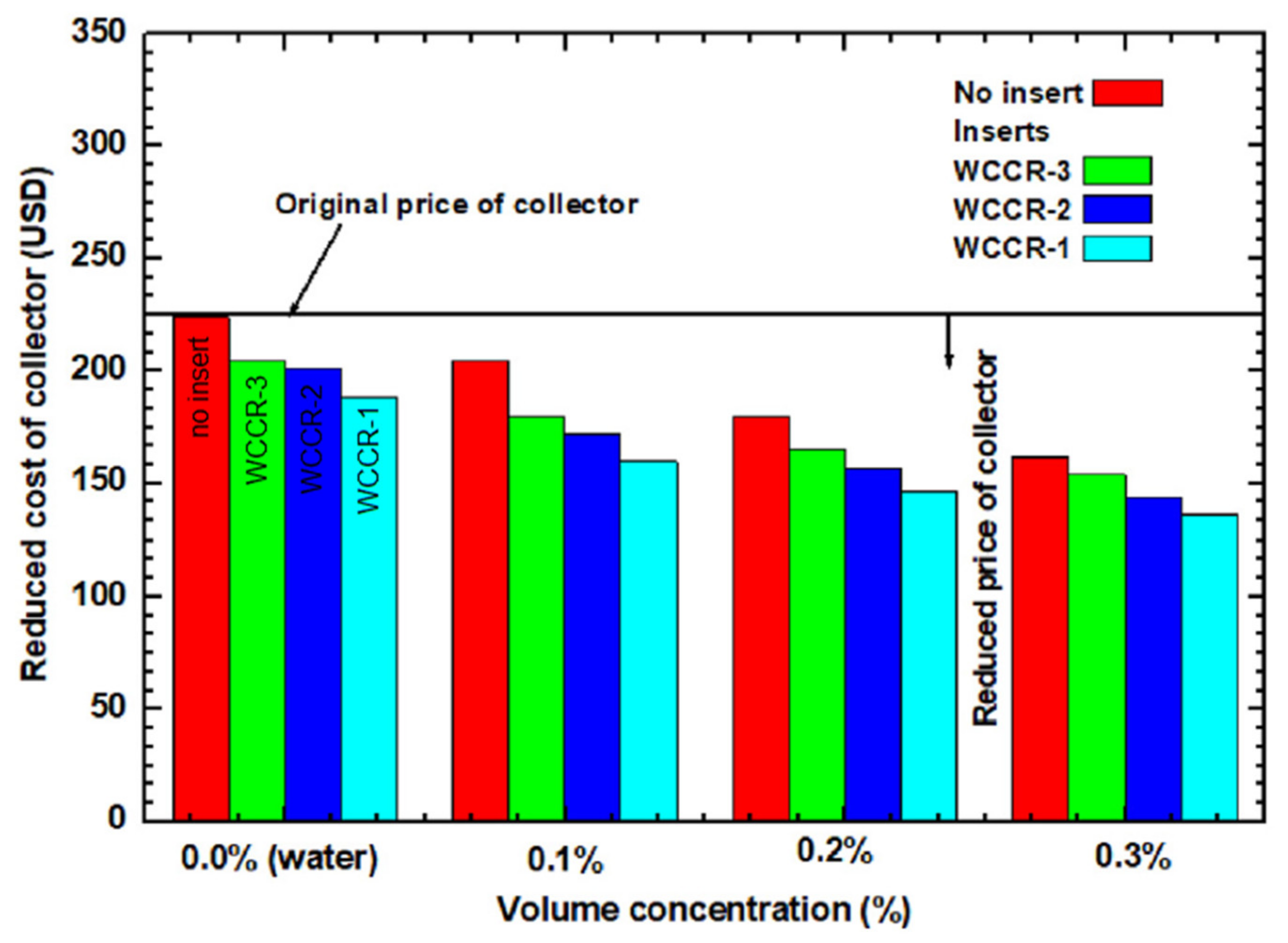
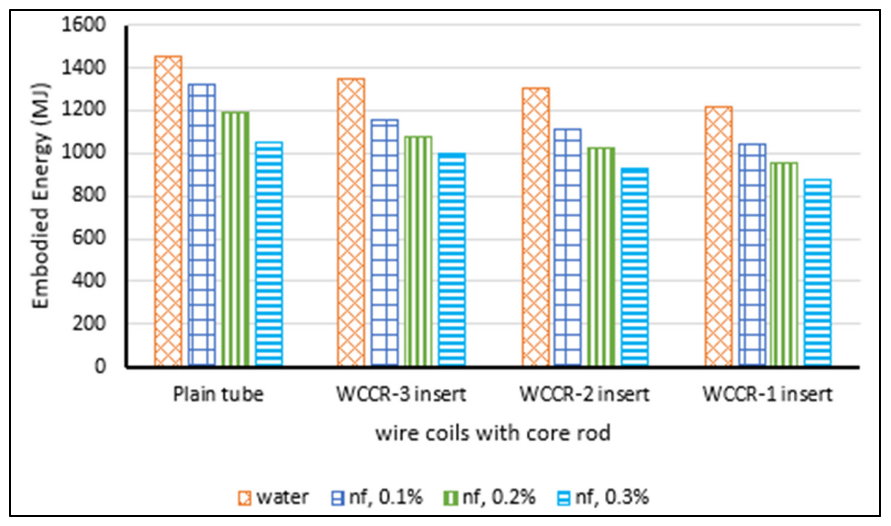
- Sundar, L.S.; Sintie, Y.T.; Said, Z.; Singh, M.K.; Punnaiah, V.; Sousa, A.C.M. Energy, efficiency, economic impact, and heat transfer aspects of solar flat plate collector with Al2O3 nanofluids and wire coil with core rod inserts. Sustain. Energy Technol. Assess. 2020, 40, 100772. [Google Scholar] [CrossRef]
- Faizal, M.; Saidur, R.; Mekhilef, S.; Hepbasli, A.; Mahbubul, I.M. Energy, economic, and environmental analysis of a flat-plate solar collector operated with SiO2 nanofluid. Clean Technol. Environ. Policy 2014, 17, 1457–1473. [Google Scholar] [CrossRef] [Green Version]
- Lukmon Owolabi, A.; Al-Kayiem, H.H.; Baheta, A.T. Performance investigation on a thermal energy storage integrated solar collector system using nanofluid. Int. J. Energy Res. 2016, 41, 650–657. [Google Scholar] [CrossRef]
- Tiwari, A.K.; Pradyumna, G.; Sarkar, J. Solar Water Heating Using Nanofluids—A Comprehensive Overview and Environmental Impact Analysis. Int. J. Emerg. Technol. Adv. Eng. 2013, 3, 221–224. [Google Scholar]
- Kang, W.; Shin, Y.; Cho, H. Economic Analysis of Flat-Plate and U-Tube Solar Collectors Using an Al2O3 Nanofluid. Energies 2017, 10, 1911. [Google Scholar] [CrossRef] [Green Version]
- Caliskan, H. Energy, exergy, environmental, enviroeconomic, exergoenvironmental (EXEN) and exergoenviroeconomic (EXENEC) analyses of solar collectors. Renew. Sustain. Energy Rev. 2017, 69, 488–492. [Google Scholar] [CrossRef]


| Category | Example | Temperature Range (°C) | Efficiency (%) |
|---|---|---|---|
| Non-concentrating | Flat-plate | up to 75 | 30–50 |
| Evacuated tube | up to 200 | ||
| Medium concentrating | Parabolic cylinder | 150 to 500 | 50–70 |
| High concentrating | Paraboloidal | 1500 and more | 60–75 |
| Name | Material | k (W/m∙K) | Cp (J/kg∙K) | ρ (kg/m3) |
|---|---|---|---|---|
| Gold | Au | 317 | 129 | 19,300 |
| Silver | Ag | 430 | 235 | 10,490 |
| Copper | Cu | 400 | 385 | 8933 |
| Nickle | Ni | 90.7 | 444 | 8900 |
| Iron | α-Fe | 80.2 | 447 | 7870 |
| Zinc | Zn | 116 | 388 | 7135 |
| Diamond | C | 3300 | 509 | 3530 |
| Aluminum | Al | 237 | 904 | 2700 |
| Silicon | Si | 148 | 714 | 2320 |
| Graphite | C | 120 | 701 | 2160 |
| Sodium | Na | 72.3 | 1230 | 968 |
| Cerium oxide | CeO2 | 6 | 616.4 | 7216 |
| Zinc oxide | ZnO | 29 | 514 | 5600 |
| Tin oxide | SnO2 | 31.38 | 343 | 5560 |
| Zirconia | ZrO2 | 1.7 | 504 | 5500 |
| Hematite iron oxide | α-Fe2O3 | 12.55 | 650.64 | 5260 |
| Fe3O4 | 6 | 670 | 5180 | |
| Magemite iron oxide | γ-Fe2O3 | 5 | 653 | 4870 |
| Ferri hydride (goethite) | α-FeOOH | - | - | 4260 |
| Titania | TiO2 | 8.9 | 686 | 4250 |
| Alumina | γ-Al2O3 | 40 | 765 | 3970 |
| Manganese oxide | MgO | 55 | 874 | 3580 |
| Silica | SiO2 | 1.4 | 745 | 2220 |
| Hybrid | MgO + Ag | 242 | 554.5 | 7035 |
| Hybrid | MWCNT + Fe3O4 | 509.14 | 680.66 | 4845.4 |
| Silicon carbide | SiC | 490 | 675 | 3160 |
| Titanium carbide | TiC | 330 | 711 | 4930 |
| Carbon nanotube | CNT | 3000 | 1350 | |
| Single-wall CNT | SWCNT | 3500 | 1380 | 1400 |
| Multi-wall CNT | MWCNT | 15 | 470 | 2100 |
| Aluminum nitride | AlN | 285 | 740 | 3260 |
| No. | Basis | Model | Validity |
|---|---|---|---|
| Model I | Concepts of mixing theory for ideal gas mixtures | dilute suspension | |
| Mode II | Assumption of thermal equilibrium between nanoparticles and the surrounding base fluid | more accurate | |
| Model III | Isobaric specific heat capacity | same as Model I |
| Owner | Model | Validity |
|---|---|---|
| Maxwell |
| |
| Xuan |
| |
| Hamilton– Crosser |
| |
| Wasp |
| |
| Brueggemann |
| |
| Yu and Choi |
| |
| Pack and Cho |
| |
| Lu and Lin |
|
| Owner | Model | Validity |
|---|---|---|
| Einstein |
| |
| Brinkman |
| |
| Batchelor |
| |
| Graham |
| |
| Kreiger– Dougherty |
| |
| η = 2.5 for spherical particles | ||
| ∅p.max = maximum volume fraction = 0.605 (0.001 ≤ ϕp ≤ 0.05) | ||
| Nielson |
|
| Model | Base Fluid | Ref. |
|---|---|---|
| (a) Conductivity | ||
| Water | [98] | |
| Water | [68] | |
| PG40 | [99] | |
| EG40 | [100] | |
| EG60 | [101] | |
| (b) Viscosity | ||
| Water | [85] | |
| Water | [68] | |
| PG40 | [99] | |
| EG40 | [100] | |
| EG60 | [101] | |
| (c) Density | ||
| Water | [68] | |
| PG40 | [99] | |
| EG40 | [100] | |
| EG60 | [101] | |
| (d) Heat capacity | ||
| Water | [68] | |
| PG40 | [99] | |
| EG40 | [100] | |
| EG60 | [101] | |
| Model | Ref. |
|---|---|
| [102] | |
| [102] | |
| [102] | |
| [103,104] | |
| [105] | |
| [106,107] | |
| [108] | |
| [44] | |
| [109,110] | |
| [111,112] | |
| For developing flow and Re > 10,000 | |
| [113,114] | |
| [115] | |
| [58,116] | |
| [68] | |
| [117] | |
| [44] | |
| [58,118] | |
| [58,119] | |
| [49] | |
| [120] | |
| [121] | |
| [121] | |
| [121] | |
| [121] | |
| [121] | |
| [121] | |
| [122] |
| Ref. | Performance Criterion | εp (%) | αp (%) | ηmax,s | Tsun (K) | E·des,Δp | Δpheader | ΔTin-air | Flow Regime | Nu Model | f Model | NP Type | BF Type | k Model | µ Model | Concentration | dp (nm) | Surfactant | Research Technique | Main Achievements |
|---|---|---|---|---|---|---|---|---|---|---|---|---|---|---|---|---|---|---|---|---|
| [131] | ηI | NS | NS | NA | 5800 | NA | NA | 0 | NS | NA | NA | Al | Wat | NS | NS | 0.8 vol.% | 5 | NA | Num | +10% in ηI |
| [153] | k | NS | NS | NA | NS | NA | NA | NA | NA | NA | NA | MWCNT | Wat | Hamilton–Crosser | NS | 1.0 vol.% | 283 | SDS | Exp | +41% in k |
| [154] | ηI | NS | NS | NA | NS | NA | NA | NS | NS | NA | NA | CNT, Graphite, silver | Wat | NS | NA | 0 to 1.0 vol.% | 6–20, 30, 20, 40 | Ana and Exp | +6% in ηI | |
| [155] | ηI | 7 | 96.2 | NA | NS | NA | NA | NA | NS | NA | NA | Al2O3 | Wat | NS | NA | 0.2 wt.% and 0.4 wt.% | 15 | Triton X-100 | Exp | +28.3% in ηI |
| [156] | ηI | 7 | 96.2 | NA | NS | NA | NA | NA | NS | NA | NA | MWCNT | Wat | NS | NA | 0.2 wt.% and 0.4 wt.% | 10–30 | Triton X-100 | Exp | decrease in ηI at 2 wt.% when not using surfactant |
| [157] | Nu | NS | NS | NA | NS | NA | NC | NS | laminar | Lin and Violi | NA | Ag, CuO | Wat | NS | NA | 0–15 vol.% | NS | NA | Num | NuAl2O3 > NuCuO |
| [134] | ηI,ηII and hfi | NS | NS | Carnot | 4350 | NC | NC | NS | laminar | Choi | Darcy | Al2O3, TiO2, SiO2, CuO | Wat | Hamilton–Crosser | NS | 0–4 vol.% | NS | NA | Ana | ηI,CuO > others +22.15% in hfi −4.34% in gen |
| [158] | ηI | NS | NS | NA | NS | NA | NA | NA | NS | NA | NS | Cu | Wat | NS | Einstein | 0.05 and 0.1 wt.% | 35 | SDS | Exp | +24% in ηI |
| [159] | ηI | <10 | >95 | NA | NS | NA | NA | NA | NS | NA | NA | CNT | Wat | NS | NS | 0.4–0.6, 1.0 wt.% | 1 | Polysorbate80 | Exp | +39% in ηI |
| [160] | μ, ρ, and Δp | NS | NS | NA | 4350 | NA | NC | NS | Laminar | NA | Darcy | Al2O3 | W:EG | Measured | Measured | 0.05 to 0.1 vol.% | 13 | NS | Theo | Insignificant change in pumping power |
| [161] | k Vsed | NS | NS | NA | NS | NA | NC | NS | Laminar and turbulent | Measured | NS | Al2O3, Fe2O3 and Al2O3 | Wat | Measured | Brinkmann | 1–3 vol.% | 45, 30 and 60 | NS | Num and Exp | +6.7% in k header modification |
| [162] | Nu | NS | NS | NA | NS | NA | NS | NA | Laminar | Shah | Darcy | Al2O3 | Wat | Sharma | Sharma | 0.02, 0.1, and 0.5 vol.% | NS | NS | Exp | +8–12% in Nu |
| [163] | ηI | NS | NS | NA | NS | NA | NA | NA | Laminar and turbulent | NA | NS | TiO2 | Wat | NS | NS | 0–0.3 wt.% | 20 | NU | Exp | Lower flow rate caused higher enhancement. Surfactant decreased efficiency. |
| [164] | ηI and hfi | 5 | 96 | NA | NS | NA | NA | NS | Laminar | NS | NA | MWCNT Al2O3 CuO | Wat | Maxwell | Einstein | 1, 2, and 3 wt.% | NS | NA | Num(CFD) | ηI,CuO > others |
| [165] | ηI | 7 | 96.2 | NA | NS | NA | NA | 0 to 90% | NS | NS | NA | CuO | Wat | NS | NS | 0.4 vol.% | 40 | NS | Exp | +21.8% in ηI |
| [166] | ηI | NS | NS | NA | NS | NA | NA | NA | NS | NS | NA | Cu + Ag | W:EG | NS | NS | 0.3 vol.% | 7 | NS | Exp | +3% in ηI |
| [167] | ηI | NS | NS | NA | NS | NA | NA | NA | NS | NS | NA | Cu | W:EG | NS | NS | 0.3 vol.% | 7 | NS | Exp | +3.2% in ηI |
| [168] | ηI | NS | NS | NA | NS | NA | NA | NA | NS | NS | NA | Cu | W:EG | Measured | Einstein | 0.2 and 0.3 wt.% | 10 | NS | Exp | +10% in ηI |
| [169] | ηI | NS | NS | NA | NS | NA | NA | NS | NS | NS | NA | Ag, Cu, Al2O3, CuO | Wat | Maxwell | Pak and Cho | 0–10% | NS | NA | Num | ηI, Ag > others opt = 5% |
| [170] | Nu and k,gen | 92 | NS | Carnot | 4350 | C | NC | 0 | Turbulent | Gnielinski | Colebrook | Al2O3, TiO2, SiO2, Cu | Wat | Xuan | Corcione | 0–4 vol.% | 25 | NA | Ana | NuAl2O3 > others Tout,Cu > others gen,TiO2 < others |
| [171] | ηI | 7 | 96.2 | NA | NS | NA | NA | NA | NS | NS | NA | NA | W:PG | NS | NA | NA | NA | NA | Exp | −15.68% in ηI (BR = 25%) −8.3% in ηI (BR > 75%) |
| [172] | ηI | NS | NS | NA | NS | NA | NA | NA | Laminar and turbulent | NS | NA | CuO | Wat | Measured | Measured | 0.05 vol.% | 75 | SDBS | Exp | ΔηI, natural > ΔηI, forced |
| [39] | ηI, Di, Gt | 5 | 95 | NA | NS | NA | NS | NS | Laminar | NS | NA | Cu | Wat | Maxwell | Pak and Cho | 2 vol.% | 5 | NA | Num (CFD) | +6% in ηI |
| [173] | ηI, pH | NS | 77 | NA | NS | NA | NA | NA | Laminar | Churchill | NA | Al2O3 CuO | Wat | Maxwell | Brinkmann | 0.1 wt.% 0.2 wt.% | 40 20 | SDS | Exp | ηI, Al2O3 > ηI, CuO at high pH |
| [174] | ηI, hfi | NS | NS | NA | NS | NA | NA | NA | Turbulent | Measured | NA | Ag | Wat | Xuan | Einstein | 0.01, 0.03, 0.04 vol.% | <100 | PVP | Exp | +18% in hfi |
| [175] | ηI | NS | NS | NA | NS | NA | NC | NA | Turbulent | NS | Blasius | Cu | Wat | Measured | Measured | 0.01, 0.02, 0.04, 0.1, 0.2 wt.% | 25 and 50 | NS | Exp | +23.83% in ηI at 0.1 wt.% |
| [176] | Q | NS | NS | NA | NS | NA | NC | NA | Laminar | McAdams | NA | ZnO | PG | Measured | Measured | 0–2 vol.% | 32.4 | NU | Exp | +23.83% in Q (heat transfer) |
| [177] | ηI | NS | NS | NA | 4350 | NA | NA | NA | NS | NS | NS | SiO2 | W:EG | NS | NS | 0.5, 0.75, 1.0 vol.% | 40 | NS | Exp | ΔηI = +4 to +8% |
| [47] | ΔTin-out | NS | NS | NA | NS | NA | NA | NA | NS | NA | NA | Al2O3 | Wat | NS | NS | 0.5 vol.% | 20–40 | NS | Exp | +4 °C in ΔT |
| [178] | ηI k | 12 | 94 | Carnot | NS | NC | NC | NA | Laminar | NS | NS | TiO2 | W:PLE | Measured | Measured | 0.1 and 0.3 vol.% | 21 | PEG400 | Exp | +34.5% in ηI +6% in k |
| [179] | ηI, ηI, dp and pH | 12 | 94 | Carnot | NS | NC | NC | NA | NS | NS | NS | Al2O3 | Wat | Measured | NS | 0.1 vol.% | 13 and 20 | NU | Exp | ηI, 13nm > ηI, 20nm by 3% ηII, 13nm > ηII, 20nm by 5% |
| [180] | ηI | 12 | 94 | Carnot | NS | C | NC | NA | NS | NS | NS | Al2O3 | Wat | Measured | NS | 0.1 and 0.3 vol.% | 13 | NS | Exp | +83.5% in ηI |
| [181] | NS | NS | NA | NS | NA | NA | NA | Laminar | Ranz–Marshall | NS | TiO2 | Wat and W:EG | Measured | Measured | 2.3 vol.% | 21 | CTAB | Num and Exp | +21% in | |
| [182] | ηI | NS | NS | NA | NS | NA | NA | NA | NS | NA | NA | Al2O3 | Wat | NS | NS | 3.0 vol.% | 45 | NS | Exp | +7% in ηI |
| [183] | ηI | 92 | 95 | NA | NS | NA | NA | NA | NS | NA | NA | MWCNT | W:EG | NS | NS | 0–100 ppm | NS | NS | Exp | +23% in ηI |
| [184] | ηI and Tout | NS | 97 | NA | NS | NA | NA | NA | Laminar | Goldberg | NA | Graphene | Wat | Measured Xuan | Measured Brinkmann | 0.01 and 0.02 wt.% | 265 | NS | Exp and Ana | +18.87% in ηI +14 °C in Tout |
| [185] | ηI | NS | NS | NA | NS | NA | NC | NA | Laminar | Shah, Churchill, and Sieder | Darcey | Graphene oxide | Wat | Measured | Measured | 0.005, 0.01, 0.02 wt.% | 300 | NU | Exp | +7.3% in ηI |
| [186] | ηI | 7 | 96.2 | NA | NS | NA | NA | NA | NS | NA | NA | Al2O3 | Wat | NS | NS | 0.15 wt.% | 20 | Triton X-100 | Exp | +18% in ηI |
| [187] | ηI and Tout | NS | NS | NA | NS | NA | NA | NA | Turbulent | NA | NA | Ag | Wat | NS | NS | 0.01, 0.03, and 0.04 vol.% | NS | NA | Num and Exp | Error = ±2% |
| [188] | ηI | NS | NS | NA | NS | NA | NA | NA | NS | NA | NA | Al2O3 | Wat | Measured | Chen | 0–3 vol.% | 45 | NA | Num | +7.54% in ηI |
| [189] | ηI and ηII | 12 | NS | Carnot and PLP | NS | C | NC | NA | Laminar | NA | Darcey | MWCNT, Graphene, CuO, Al2O3, TiO2, and SiO2 | Wat | Measured | Measured | 0–2.25 vol.% | 7, 20, 42, 45, 44, and 10 | Triton X-100 | Exp | +23.47% in ηI +29.32% in ηII |
| [190] | and hfi | NS | NS | NA | NS | NA | NC | NA | Laminar | Cerón | Darcey | Al2O3 | Wat | Xuan | Maiga | 0–4 vol.% | 25 and 100 | NA | Num (CFD) | +58% in hfi = 2% |
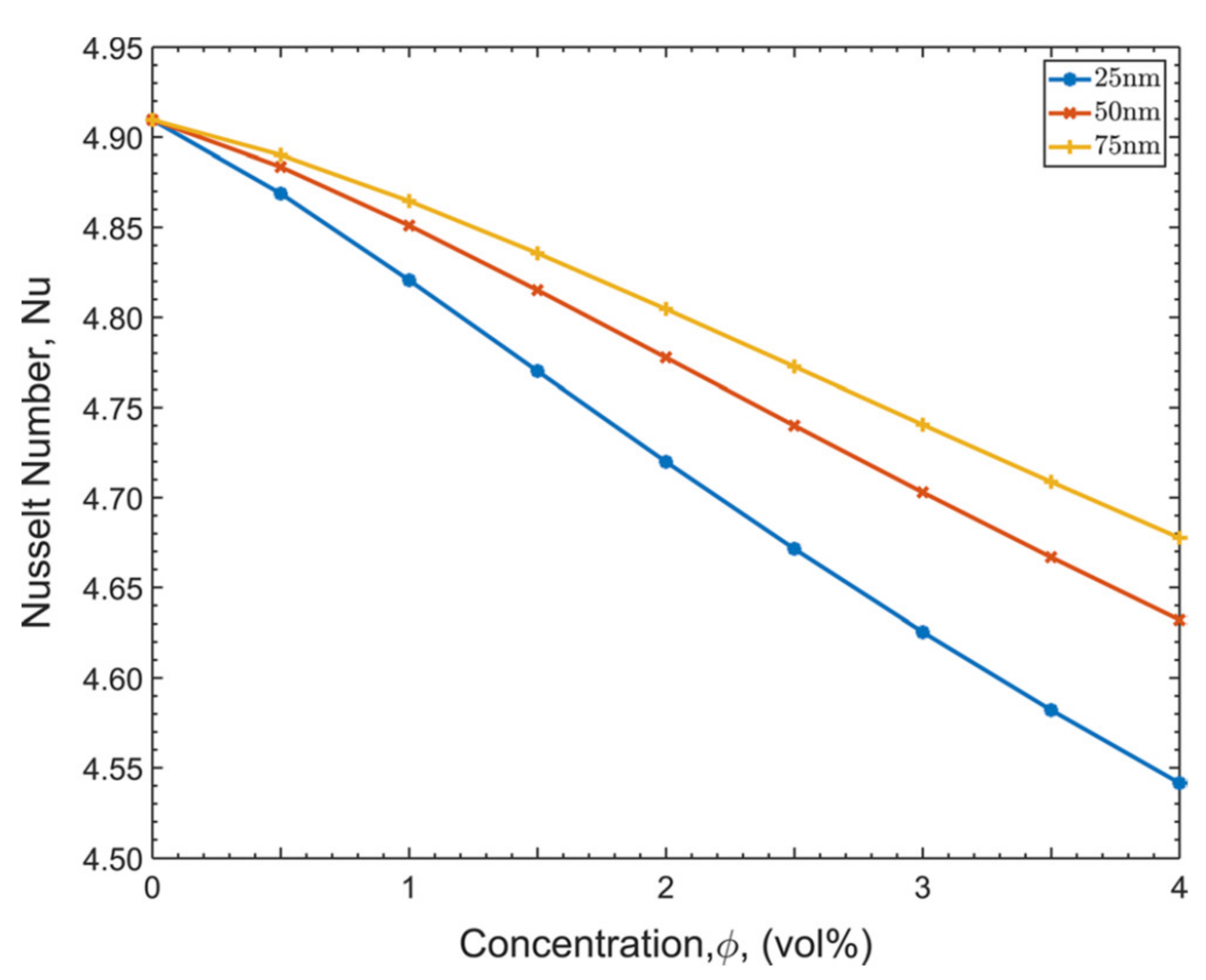
| [191] | Nu and Tout | NS | NS | NA | NS | NA | NC | NA | Laminar | Cerón | Darcey | Al2O3 | Wat | Xuan | Maiga | 0–5 vol.% | 25 | NA | Num (CFD) | Nu and Tout decreased with ɸ |
| [192,193] | ηI, absorber porosity | NS | NS | Carnot | NS | C | NC | NA | Laminar | Measured | NS | SiO2 | Wat | Xuan | Brinkmann | 0.2, 0.4, 0.6 vol.% | 25–30 | NS | Exp | +8.1% in ηI |
| [194] | Qu | 7 | 96.2 | NA | NS | NA | NA | NA | NS | NA | NA | Al2O3CuO | Wat | Xuan | NA | 0.1 vol.% | 20 40 | NS | Exp | +29.5% in Qu |
| [195] | ηI | 7 | 96.2 | NA | NS | NA | NA | NA | NS | NA | NA | Al2O3 | Wat | Calvin–Petersona | NA | 0.1 vol.% | 20 | NS | Exp | +23.5% in ηI |
| [196] | ηI | 13 | 95 | NA | NS | NA | NA | NA | NS | NA | NA | WO3 | Wat | Xuan | NA | 0.017, 0.033, 0.067 vol.% | 90 | NS | Exp | +13.48% in ηI at 0.067 vol.% |
| [197] | ηI | 13 | 95 | NA | NS | NA | NA | NA | NS | NA | NA | CeO2 | Wat | Xuan | NA | 0.017, 0.033, 0.067 vol.% | 25 | NS | Exp | +10.47% in ηI at 0.067 vol.% |
| [198] | ηI | 95 | NS | NA | NS | NA | NA | NA | NS | NA | NA | CeO2 | Wat | Xuan | Corcione | 0.01 vol.% | 25 | NS | Exp and Theo | +21.5% in ηI |
| [199] | ηI | NS | NS | NA | NS | NA | NA | NA | NS | NA | NA | Al2O3 + TiO2 | Wat | NS | Brinkmann | 0.1 wt.% | 20 + 15 | CTAB | Exp and Num | +26% in ηI |
| [200] | ηI | NS | NS | NA | NS | NA | NA | NA | NS | NA | NA | TiO2 | Wat | NS | Measured | 2 wt.% | Triton X-100 | Exp | +12.47% in ηI | |
| [201] | Q (from PV) | NS | NS | NA | NS | NA | NA | NA | NS | Shah | NA | Al2O3 | Wat | Corcione | Corcione | 0–6 vol.% | 20 and 40 | NA | Num | −5 K in PV system top side temperature |
| [202] | Tout and ηII | 5 | 95 | Carnot | 4,500 | NC | NC | NS | Laminar and Turbulent | NS | Darcey | Al2O3 | Wat | Measured | Measured | 1, 2, and 3 vol.% | NS | NA | Num | +7.20% in Tout +7.7% in ηII |
| [203] | Nu | NS | NS | NA | NS | NA | NC | NA | Turbulent | Measured and Dituss | Blasius | Al2O3 | Wat | Maxwell | Einstein | 0.3 vol.% | <20 | SDBS | Exp | +28.75% in Nu |
| [204] | hfi and | NS | NS | Carnot | 4350 | NC | NC | 0 | Laminar | hfi D/k | Darcey | SWCNT | Wat | Hamilton–Crosser | NS | 0.02–0.03 vol.% | NS | NA | Theo | +15.33% in hfi −4.34% in |
| [105] | Tout and | 92 | NS | Carnot | 4350 | C | NC | 0 | Turbulent | Gnielinski | Petukhov and Colebrook | Al2O3 | Wat | Maxwell and Xuan | Corcione and Brinkmann | 0–4 vol.% | 25, 50, 75, 100 | NA | Theo | is independent on models Tout affected by ɸ but not dp |
| [205] | Nu, and Be | NS | NS | NS | NS | NC | NC | NS | Laminar | k(∂θ/∂Y) | NA | Cu | Wat | Maxwell | Pac and Cho | 0–7 vol.% | 5 | NA | Num | Nu, and Be increased with ɸ |
| [206] | ηII and | NS | NS | Carnot | NS | NC | NC | NS | NS | NA | NA | Graphene | Wat | NS | NS | 0.02–0.035 vol.% | NS | NA | Theo | +21% in ηII −4% in |
| [207] | ηII | 7 | 96.2 | Carnot | NS | C | NC | –11 to 113 | Laminar and Turbulent | Li-Xuan and Rhosenow | Darcey and Blasius | Al2O3 | Wat | Maxwell | Batchelor | 0–3.5 vol.% | 15 | NA | Theo | +1% in ηII,opt |
| [208] | , pH, dp | 92 | NS | Carnot | 4350 | C | NC | 0 | Turbulent | Gnielinski | Petukhov | SiO2 | Wat | Xuan | Brinkmann | 1 vol.% | 12 and 16 | NA | Ana | pH decreased 12nm but increased 16nm |
| [209] | ηII | 7 | 96.2 | Carnot | NS | C | NC | –11 to 113 | Laminar and Turbulent | Li-Xuan | Darcey and Blasius | Al2O3 | Wat | Maiga | Maiga | 0–1 vol.% | 15 | SDBS | Exp and Theo | Max ηII, opt = 12.53% |
| [210] | ηII and Be | NS | NS | Carnot | 4350 | C | NC | NA | Laminar | NA | Darcey | SiO2 | W:EG | NS | NA | 0–1 vol.% | 40 | NU | Exp | +62.7% in ηII, Be increased with ɸ |
| [211] | ηI, ηII and Be | 12 | NS | Carnot | NS | C | NC | NA | Laminar | NA | Darcey | MgO | Wat | Measured | Measured | 0–2 vol.% | 40 | CTAB | Exp | +9.34% in ηI, +32.23% in ηII, Be approached 1.0 |
| [212] | ηI and ηII | NS | NS | Carnot | NS | NS | NA | NA | NS | NS | NS | C Fe3O4 Ag | Wat | NS | NS | 5–40 ppm | 40 15 20 | TPABr | Exp | ηIandII, Fe3O4 > others |
| [213] | ηI, ηII and Be | 12 | NS | Carnot | NS | C | NC | NA | Laminar | NA | Darcey | MgO + MWCNT CuO + MWCNT | Wat | Measured | Measured | 0–2.25vol.% | 40 + 7 42 + 7 | NS | Exp | +16.28% in ηI +25.1% in ηII, Be approached 1.0 |
| [214] | ηI | NS | 95 | NA | NS | NA | NA | 5–40 | NS | NA | NA | Graphene | Wat | Maxwell | NS | 0.025, 0.075, 0.1 wt.% | 2 | NS | Exp | +18.2% in ηI at 0.1 wt.% |
| [215] | ηI and ηII | NS | NS | Carnot | NS | NA | NA | NS | NS | NA | NA | Al2O3 | Wat | NA | NA | 0.1vol.% | 20 | NS | Exp | +30.7% in ηI +18.7% in ηII |
| [216] | Δp and V | NS | NS | NA | NS | NA | C | NS | Turbulent | NA | NS | Al2O3, TiO2 Zno | Wat | Maxwell | Einstein | 0.1vol.% | NS | NA | Modeling | Average number of risers perform better |
| [217] | ηI | 12 | NS | NA | NS | NA | NA | 38–58 | Laminar | Heaton | NA | SiO2 | Wat | Measured | Measured | <0.6vol.% | 20–30 | NS | Exp and Ana | +55.2% in FRUL |
| [218] | ηI | 7 | 96.2 | NA | NS | NA | NA | 4–40 | NS | NA | NA | CuO | Wat | NA | NA | 0.1 vol.% | 40 | NS | Exp | +55.2% in ηI at 4 Lit/min |
| [219] | ηI | NS | NS | NA | NS | NA | NA | 1–6 | Laminar | Heaton | NA | Al2O3 | Wat | Maxwell | Kitano | 0.25–5 vol.% | 11 | NS | Exp and Theo | –11.7 % in ηI |
| [220] | ηI | NS | NS | NA | NS | NA | NA | 2–5 | NS | NA | NA | Al2O3 | Wat | Yu and Choi | Drew and Passman | 0.1–0.3vol.% | 10–15 | SDS | Exp | +21.3% in ηI |
| Ref. | Performance Criterion | εp (%) | αp (%) | ηex,max | Tsun (K) | E·des,Δp | Δpheader | ΔTin-air | Flow Regime | Nu Model | f Model | NP Type | BF Type | k Model | μ Model | Concentration | dp (nm) | Surfactant | Type of Research | Main Achievements |
|---|---|---|---|---|---|---|---|---|---|---|---|---|---|---|---|---|---|---|---|---|
| [15] | Cm | NA | NA | NA | NA | NA | NA | NA | Laminar and turbulent | Hausen | Darcey and Fanning | Al2O3, CuO, TiO2 | Wat and W:EG | Corcione | Corcione | 0–0.05 vol.% | 25–100 | NA | Theo | |
| [228] | ηI and ctot | NS | NS | NA | NS | NA | NA | NA | turbulent | experimental and Gnielinski | experimental and Blasius | Al2O3 | Wat | Maxwell | Einstein | 0.1, 0.2, and 0.3 vol.% | NS | SDBS | Exp | +26.4% in ηI −88 $ in Ctot, and −39.4% in embodied energy |
| [229] | Cmfr and CO2 | 12 | 94 | Carnot | 4500 | C | NC | NA | Laminar | Choi | Darcey | Al2O3, CuO, TiO2, SiO2 | Wat | Hamilton–Crosser | Measured | 0.2 and 0.4 vol.% | 15 | NS | Exp | −220 MJ in embodied energy Payback = 2.4 yr. −170 kg in emission |
| [230] | ηI, Cm, Cmfr, and CO2 | NS | NS | NA | NA | NA | NA | NA | NS | NA | NA | Fe | W:PG | Measured | NA | 0.5 wt.% | 40 | NS | Exp | +9% in ηI −28.5% in annual cost −9.5% in embodied energy −37% in CO2 |
| [225] | ηI and C | 92 | NS | NA | NS | NA | NC | 0 | Turbulent | Vajjha | Fanning | Al2O3 | Wat | Calvin–Petersona | Wang | 0–0.1 vol.% | NS | NA | Theo | +2% in ηI −3.5% in C |
| [198] | C and Cmfr | 95 | NS | NA | NS | NA | NA | NA | NS | NA | NA | CeO2 | Wat | Xuan | Corcione | 0.01 vol.% | 25 | NS | Exp and Theo | −11.5% in total cost −28.9% in embodied energy |
| [231] | CO2 | NS | 95 | NA | NS | NA | NA | NS | NS | NA | NA | Al2O3 | Wat | NS | NA | 1.5 wt.% | NS | NA | Theo | −31% in kg-CO2/kWh |
| [232] | ηI, CO2 and SO2 | NS | 95 | NA | NS | NA | NA | NA | NS | NA | NA | Al2O3 | Wat | NS | NA | 0.5, 1, and 1.5 vol.% | 20, 50, and 100 | NS | Exp | +14.8% in ηI −190 kg, −557 kg, and −2.03 kg in Coal, CO2, and SO2 |
Publisher’s Note: MDPI stays neutral with regard to jurisdictional claims in published maps and institutional affiliations. |
© 2020 by the authors. Licensee MDPI, Basel, Switzerland. This article is an open access article distributed under the terms and conditions of the Creative Commons Attribution (CC BY) license (http://creativecommons.org/licenses/by/4.0/).
Share and Cite
Shamshirgaran, S.R.; Al-Kayiem, H.H.; Sharma, K.V.; Ghasemi, M. State of the Art of Techno-Economics of Nanofluid-Laden Flat-Plate Solar Collectors for Sustainable Accomplishment. Sustainability 2020, 12, 9119. https://0-doi-org.brum.beds.ac.uk/10.3390/su12219119
Shamshirgaran SR, Al-Kayiem HH, Sharma KV, Ghasemi M. State of the Art of Techno-Economics of Nanofluid-Laden Flat-Plate Solar Collectors for Sustainable Accomplishment. Sustainability. 2020; 12(21):9119. https://0-doi-org.brum.beds.ac.uk/10.3390/su12219119
Chicago/Turabian StyleShamshirgaran, Seyed Reza, Hussain H. Al-Kayiem, Korada V. Sharma, and Mostafa Ghasemi. 2020. "State of the Art of Techno-Economics of Nanofluid-Laden Flat-Plate Solar Collectors for Sustainable Accomplishment" Sustainability 12, no. 21: 9119. https://0-doi-org.brum.beds.ac.uk/10.3390/su12219119