1. Introduction
According to the World Data Bank [
1], the percentage of urban population has increased by 10 points in the 21st century (in 2000, the urban population was 46%, and in 2020 it reached 56%), and it is expected to reach 70% by 2050. This undoubtedly forces cities to undertake a sustainable transformation of their urban model, and society to use alternative transports. Although public transport plays an important role, a recent analysis has quantified a 60% decrease in public ridership due to the COVID-19 pandemic [
2]. Most people have swapped public transport for private cars, and few have chosen the bike. This decision, widely extended across society, negatively affects the air quality and, consequently, urban population health [
3].
Therefore, in these times in which people receive daily instruction to avoid social interaction (fear of sharing with another person) while humanity must continue to preserve sustainability and respect for the environment, it is crucial to develop urban transport solutions that guarantee the ineviTable 1.5 m physical distance while preserving our planet. In this sense, battery-powered unipersonal vehicles show some challenges not yet resolved. Firstly, the batteries are heavy and have great proportions, in terms of limited specific power [
4]. Regarding autonomy, specific energy can also be limiting with respect to interurban mobility. Batteries also have considerable degradation during their lifetime. This implies a lower performance in the electric vehicles over time [
5,
6]. Additionally, with the increased use of electric vehicles, a large number of batteries is required to be produced. However, the raw materials, such as lithium, are limited, and recycling will not be enough to continue supplying lithium in a few decades. It would not make sense to repeat the political and economic fights regarding fossil fuels to new materials [
7]. Additionally, safety issues must also be taken into account; in recent years, there have been numerous cases of Li-ion battery fires and explosions, resulting in property damage and bodily injuries [
8,
9,
10]. On the other hand, the design and fabrication of new sustainable electrode materials is taking on greater importance in recent years, so that they may be used as a substitute for traditional raw materials [
11,
12].
Thus, sustainable alternatives with hydrogen as the energy carrier, obtained from renewable energy [
13], are being considered for urban mobility in electric unipersonal vehicles [
14,
15,
16,
17,
18]. Hydrogen-powered unipersonal electric vehicles offer advantages such as fast charging, long range and low on-board pressure. Pressure tanks are the best option for the hydrogen delivery when low hydrogen demand is needed, and the distances are short between hydrogen production and delivery sites [
19].
Comparing the behavior of battery-powered unipersonal electric vehicles versus hydrogen-powered unipersonal electric vehicles, this work presents the advantages in terms of high efficiency, high power density, fast start-up and response to load changes, and long life in favor of the latter. However, there are also disadvantages, such as the current cost of hydrogen technology and the availability of recharging points. As far as technological development is concerned, and in comparison with previous scientific works found in the literature, this paper presents important novelties such as the specific design of the test platform, the use of comparable propulsion systems and real tests in a controllable urban circuit [
20,
21,
22,
23].
Table 1 shows the main conclusions obtained from the scientific literature. The different technological configurations include the use of batteries, as well as the use of hydrogen through fuel cells (FCs), solar propulsion and various combinations. In comparison to these works, this paper makes a proposal for sustainable urban mobility in which two technologies, battery and the hybridization of battery + hydrogen, are compared, obtaining a scalable model with great autonomy and fast recharge.
2. Materials and Methods
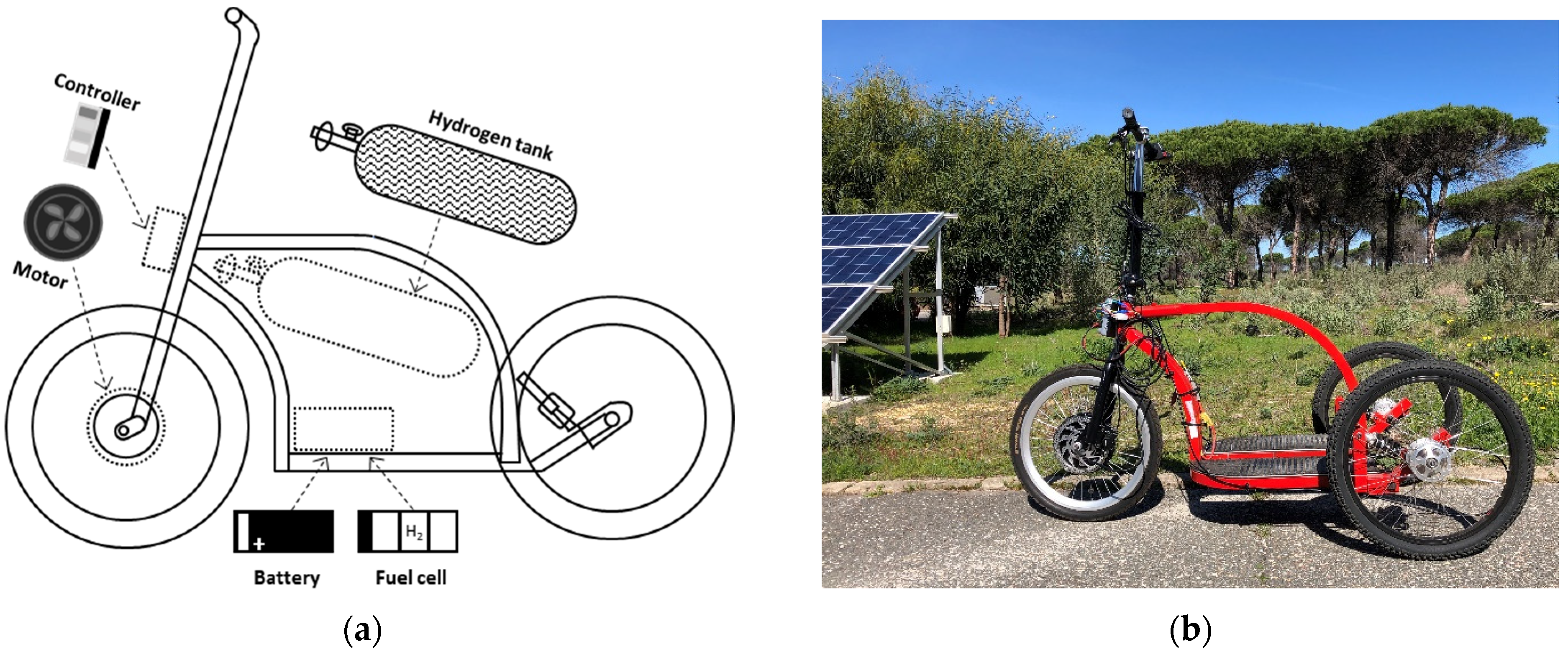
To demonstrate the capabilities of hydrogen hybridization in electric urban transport versus battery-based technology, two unipersonal vehicles were designed: a battery-powered unipersonal electric vehicle and a hydrogen-based unipersonal electric vehicle. The goal was to mount the battery-based and the hydrogen-based powertrains on similar platforms and ensuring the total weight of the unipersonal electric vehicle was the same in both cases.
Figure 1 shows the platform built with an iron chassis including all the components of the propulsion system. It should be noted that the hydrogen used in these facilities was green hydrogen, produced from renewable sources [
28,
29,
30].
The platform integrated an electric motor of 24 V and 250 W by Golden Motor
®, model MP3-20F Magic Pie
® 3, attached to the front 20-inch wheel. It was sized in a range to meet the typical energy requirements in commercial batteries and fuel cells [
31,
32,
33,
34], promoting design scalability. The system was regulated through the programmable controller, model Magic
® MX25 BAC-281P by Golden Motor
®. System specifications are summarized in
Table 2.
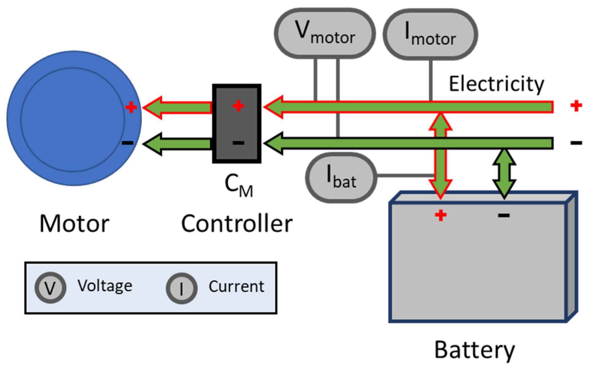
2.1. Battery-Powered Unipersonal Electric Vehicle Configuration
The first design was based on the implementation of an electric unipersonal vehicle powered by battery,
Figure 2 The motor, managed though its controller C
M, receives the necessary current directly from the battery, and the motor operating voltage matches with battery nominal voltage. In addition to the specific parameters previously described, motor voltage V
motor, current I
motor and battery current I
bat were monitored. Battery technical characteristics are summarized in
Table 3.
2.2. Hydrogen-Powered Unipersonal Electric Vehicle Configuration
The hydrogen-based propulsion system bases its energy input on hydrogen technology together with a buffer battery,
Figure 3.
The hydrogen-powered unipersonal electric vehicle has a hydrogen storage tank able to store up to 7 L, at a maximum pressure of 350 bar. The pressure of the stored hydrogen is reduced through the regulator RFC. This reduction is carried out to adapt the hydrogen to the range of inlet pressure in the fuel cell. The selected fuel cell was the BMPower® 500, with a nominal power of 500 W. Due to commercial availability and cost/nominal power effective ratio, this model was the most suitable according to the requirements of the application (the objective is to compare two platforms with similar weight). To guarantee a safe operation, both inlet pressure, PI, and output pressure, PO, obtained at the ends of the regulator were monitored.
To allow hydrogen flow into the fuel cell, the inlet solenoid valve, EI, is activated. The fuel cell produces electricity and water, from hydrogen and oxygen. A fan was used to blow the air from outside to provide oxygen to the cathode and to cool the fuel cell.
The electricity produced by the fuel cell passes through a DC/DC power converter that, through the controller CFC, regulates the output according to the power demanded by the motor and the buffer battery’s state of charge. The integration of the buffer battery aims to provide greater specific power and flexibility to the system in the face of demand peaks from the motor.
The motor controller, CM, is based on the electromechanical systems of the electric vehicle, which are accelerator and brake. The fuel cell controller, CFC, monitors hydrogen pressures PI and PO, fuel cell temperature TFC, fuel cell voltage Vfuel cell, fuel cell current before the converter Ifuel cell and after the converter Ifuel cell DC/DC, buffer battery current Ibat, motor voltage Vmotor, and motor current Imotor. Based on these variables, and the operating instructions, the controller acts on the hydrogen inlet, EI, to supply the hydrogen to the fuel cell, and on the purge solenoid valve, EO, to periodically purge the hydrogen not consumed by the fuel cell, ventilation system and air supply, and establishes a power command for the output of the DC/DC converter.
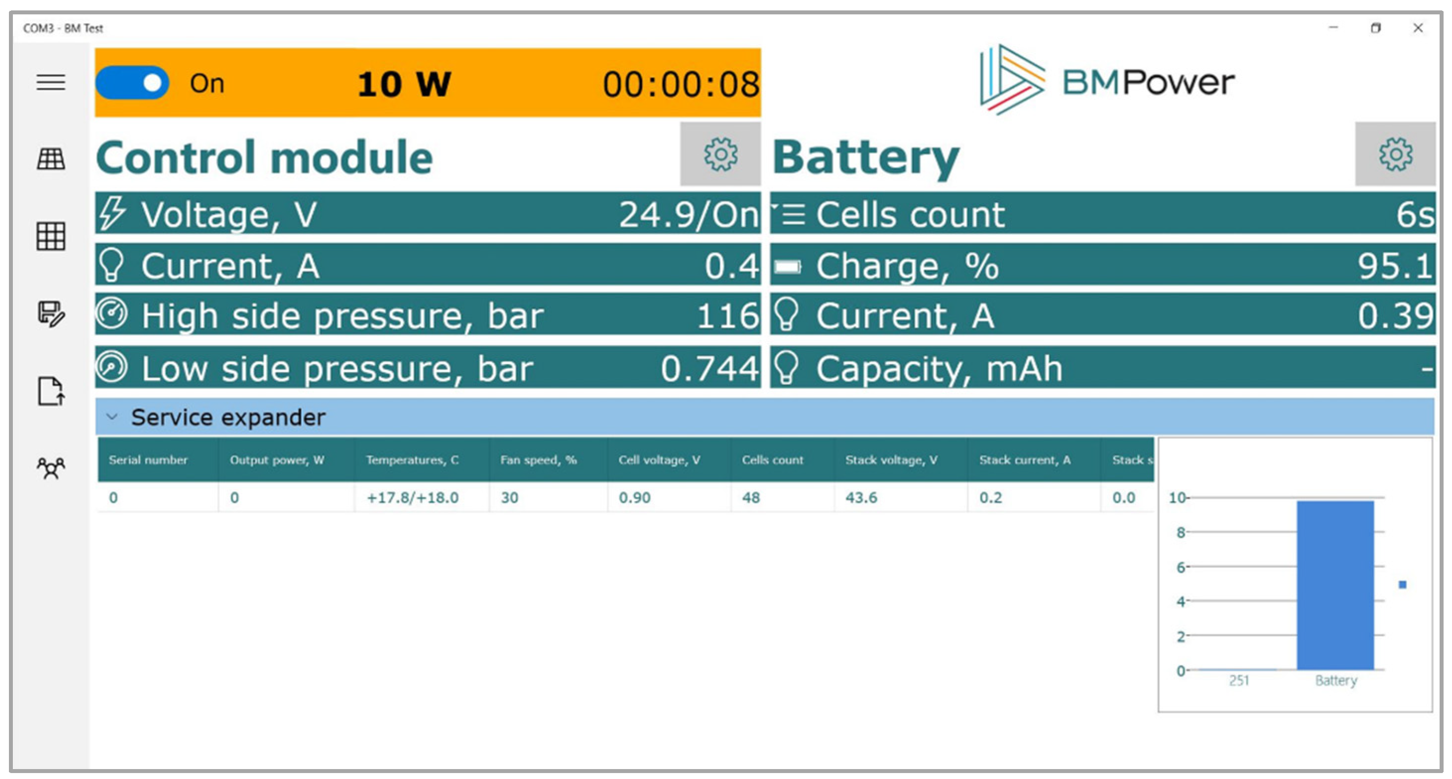
These parameters were monitored through a Wi-Fi connection and recorded during the experimental tests of the system. The BM Power
® software tool is intended for monitoring and controlling the operation of the propulsion system,
Figure 4. Technical specifications of the hybrid propulsion system are shown in
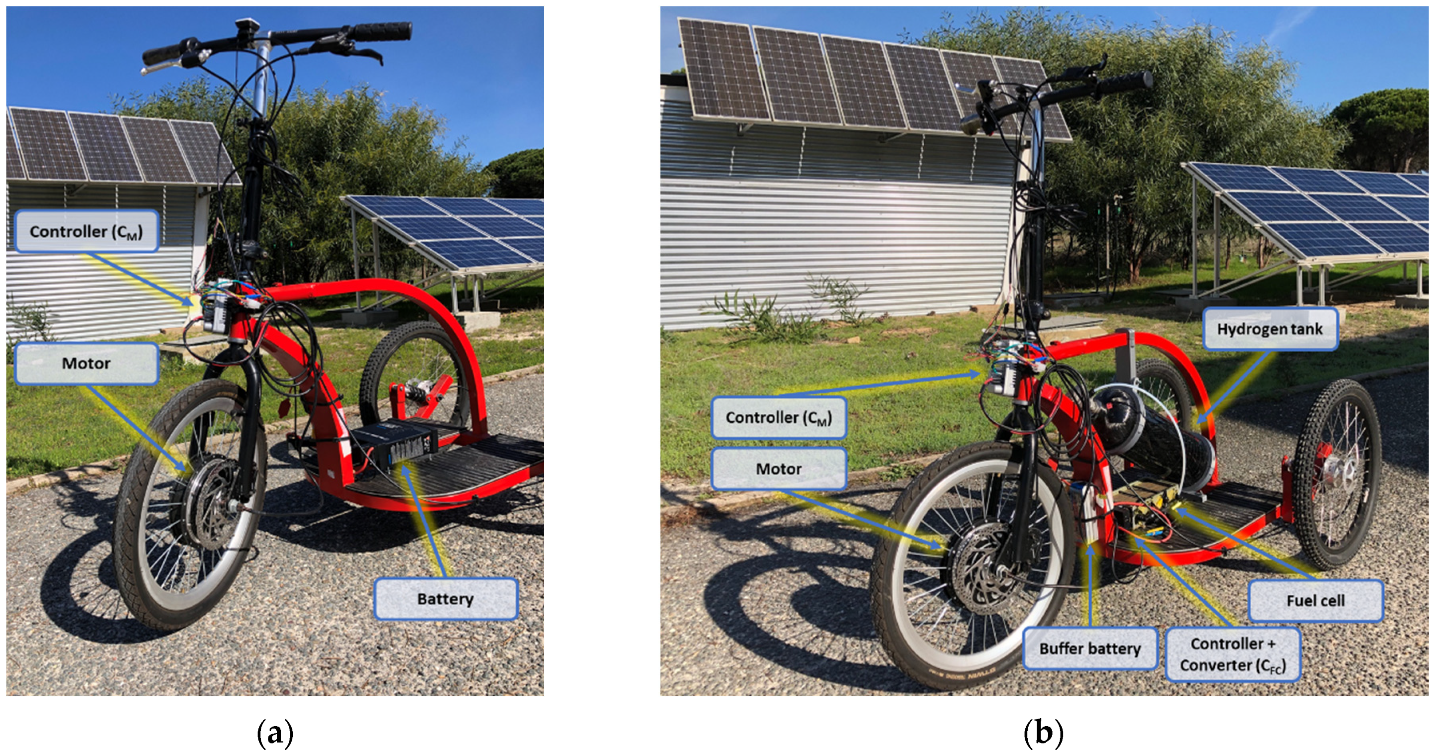
Table 4 2.3. Physical Implementation—Battery vs. Hydrogen Technology Comparison
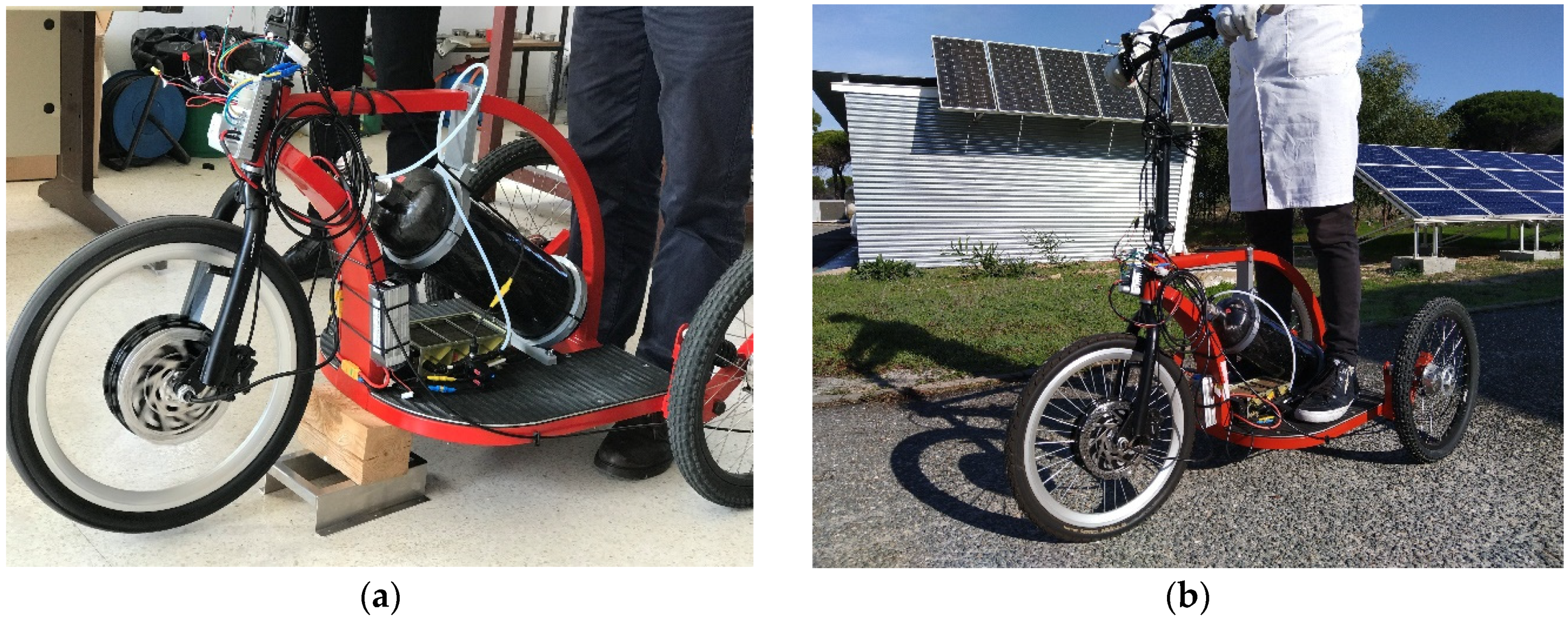
Figure 5 shows the physical implementation of the battery-based and the hybridized hydrogen-based unipersonal electrical vehicle. Both were implemented in the same platform, with an arrangement that allowed the pilot to manage and guaranteed an adequate air flow for correct ventilation and air supply.
The technology comparison was carried out regarding the energy capacity of each design.
The specific energy supplied by the battery-based system is calculated by applying Equation (1):
where:
Then, the battery specific energy is 74 Wh/kg.
In the hydrogen-based system, to calculate the specific energy it is necessary to know the amount of hydrogen stored in the tank. The hydrogen moles number,
, can be obtained from Equation (2):
where:
Therefore, the hydrogen tank provides 78.9359 mol of H2.
To obtain the hydrogen energy, hydrogen properties considered are:
HHVH2 (hydrogen higher heating value) = 141.86 MJ/kg.
The hydrogen energy provided is 6221 Wh; and the hydrogen specific energy supplied is obtained by applying Equation (3):
where:
Then, the hydrogen specific energy provided is 1481 Wh/kg.
The hybridized hydrogen-based system also included a buffer battery of 73 Wh and 0.5 kg. Applying the Equation (1), the buffer battery specific energy is 146 Wh/kg, while full hybrid system specific energy is 1339 Wh/kg.
Additionally, to compare the energy–volume relation in both powertrains, it is necessary to know the whole volume of each system. The battery-based powertrain volume is 2139 cm3. In the hydrogen-based powertrain, the tank volume is 7958 cm3, fuel cell volume is 3289 cm3 and buffer battery volume is 243 cm3. Therefore, the battery-based powertrain energy-volume relation is 124,357 Wh/m3, while in the hydrogen-based powertrain the relation is 541,426 Wh/m3.
Quantitative comparison of both platforms is shown in
Table 5; improvements were verified both in specific energy and energy–volume relation for the hydrogen-based design. This can be quantified as an increase of 1790% in specific energy and 335% in energy–volume relation.
3. Results
To obtain the experimental data results, dynamic laboratory and dynamic road tests were carried out over the two configurations: battery-based and hydrogen-based unipersonal electric vehicle,
Figure 6.
The dynamic laboratory test consisted of applying acceleration over the motor, and then provoking friction or manual braking. For the dynamic road test, a real driving test was applied over the unipersonal electric vehicle in movement.
3.1. Experimental Test from Battery-Powered Unipersonal Vehicle
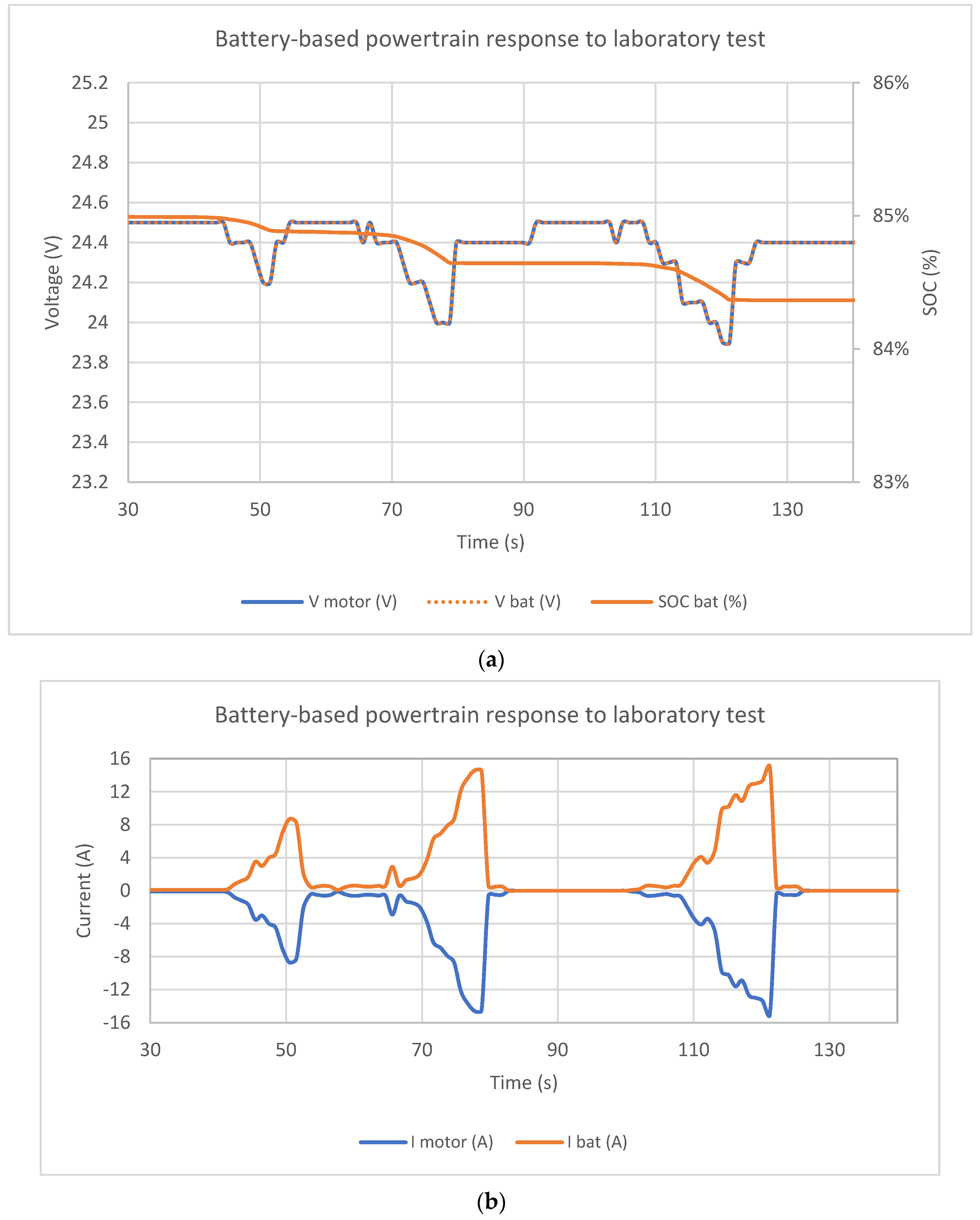
To check the battery-powered unipersonal vehicle platform, it was firstly subjected to a dynamic laboratory driving profile,
Figure 7. Different acceleration stages were applied, causing friction or manual braking. As it can be observed, the battery current followed the motor current demand, I
bat = −I
motor (authors considered a positive sign when current was leaving the device, and negative sign when current was entering the device). State of charge [
35] of the battery (SOC) was calculated applying Equation (4):
where:
is state of charge in a time ;
is the SOC at the previous instant;
is the battery current (A);
is nominal capacity of the battery (Ah);
is time differential (s).
The second test consisted of an evaluation of the battery-based unipersonal electric vehicle behavior, when it was put on-road. Battery supplied the motor demand, and as a consequence, the battery SOC decreased with time,
Figure 8.
3.2. Experimental Test from Hydrogen-Powered Unipersonal Vehicle
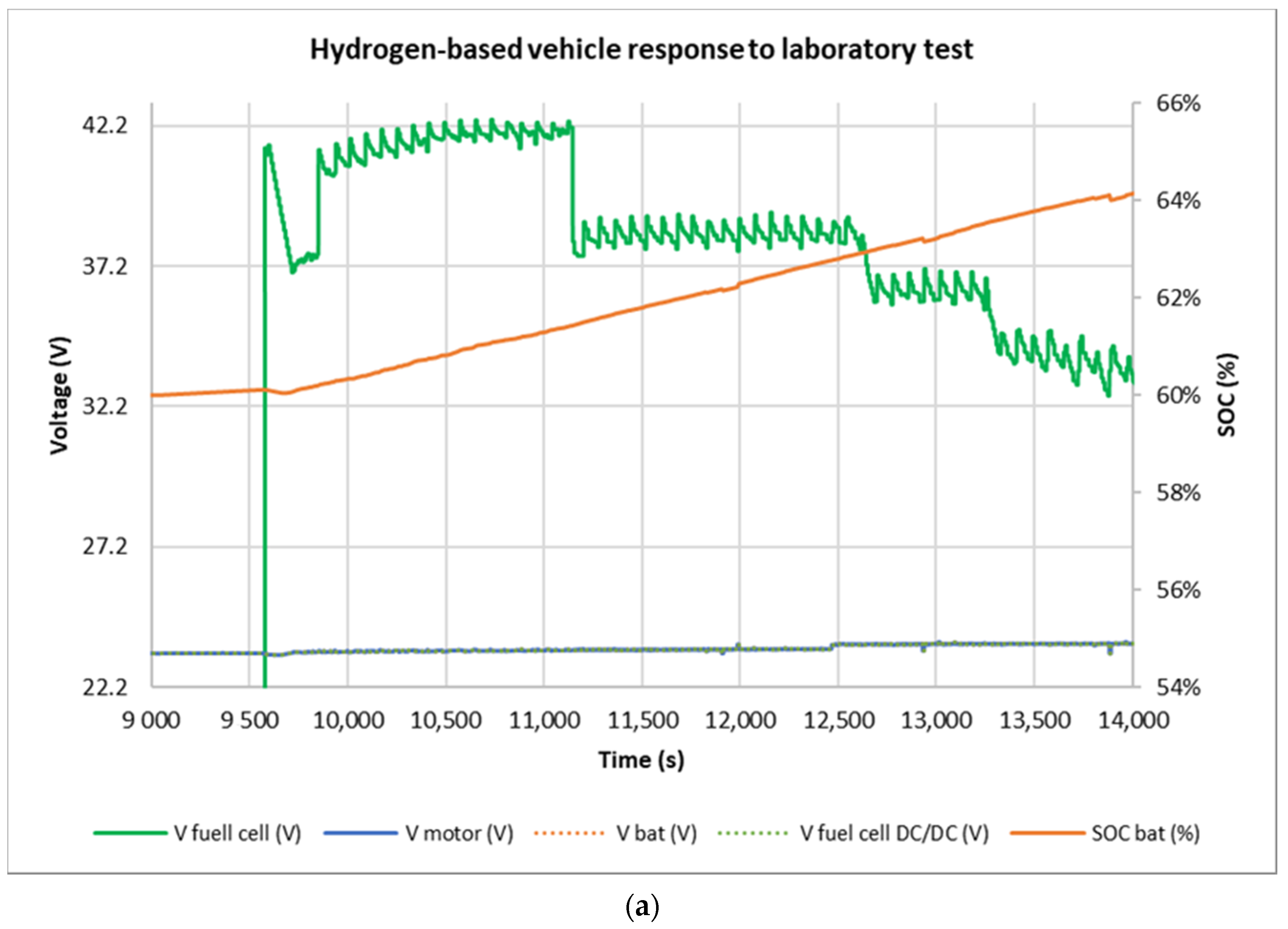
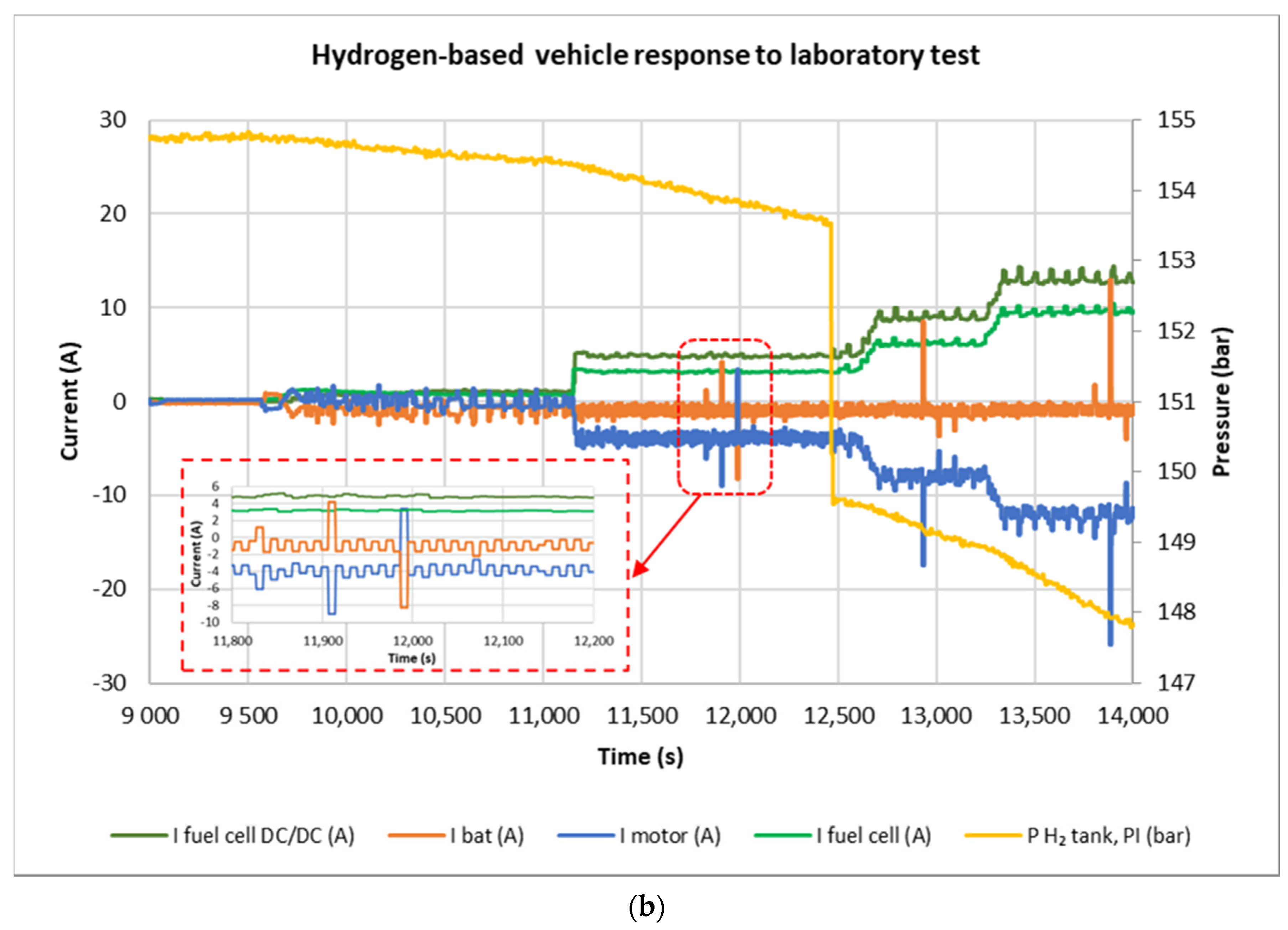
In this case, the test consisted of evaluating the unipersonal electric vehicle behavior when the powertrain was hybridized with a fuel cell and the battery. As demonstrated above, in the first test, the hybrid hydrogen-based unipersonal vehicle was subjected to a laboratory dynamic driving profile. This test observed the initial current hybridization between the fuel cell current and the buffer battery current to satisfy the current demanded by the motor. The motor voltage was fixed by the battery (nominal voltage 24 V), and the fuel cell converter acted as step-down stage (fuel cell voltage varied between 42.2 V and 33.2 V, and it reduced to 24 V). Based on the difference between the motor demand and the maximum current supplied by the fuel cell, the controller varied the converter duty-cycle with the aim to put the fuel cell into the appropriate operating point.
When the motor demand was lower than the maximum fuel cell current, the controller adjusted the DC/DC converter to put the fuel cell operating at the point that satisfies the motor demand, and the remaining current was used to recharge the battery (I
bat = −1 A),
Figure 9. Note that the fuel cell provided almost all of the motor current demand. Sudden changes in the demand were reflected in the fuel cell. The battery filtered instabilities and provided current peaks when the demand was higher than the fuel cell nominal current. Through the test, as the battery absorbed current from fuel cell, the battery SOC increased gradually. Hydrogen was consumed, so the pressure in the tank was reduced. Power balance can be at each operating point; for example, at t = 12,000 s, I
fuelcell = 4.2 A, which converted to I
fuel cell DC/DC = 5.1 A. Fuel cell converter output current was consumed by the motor (I
motor = −4.1 A) and the battery (I
bat = −1 A).
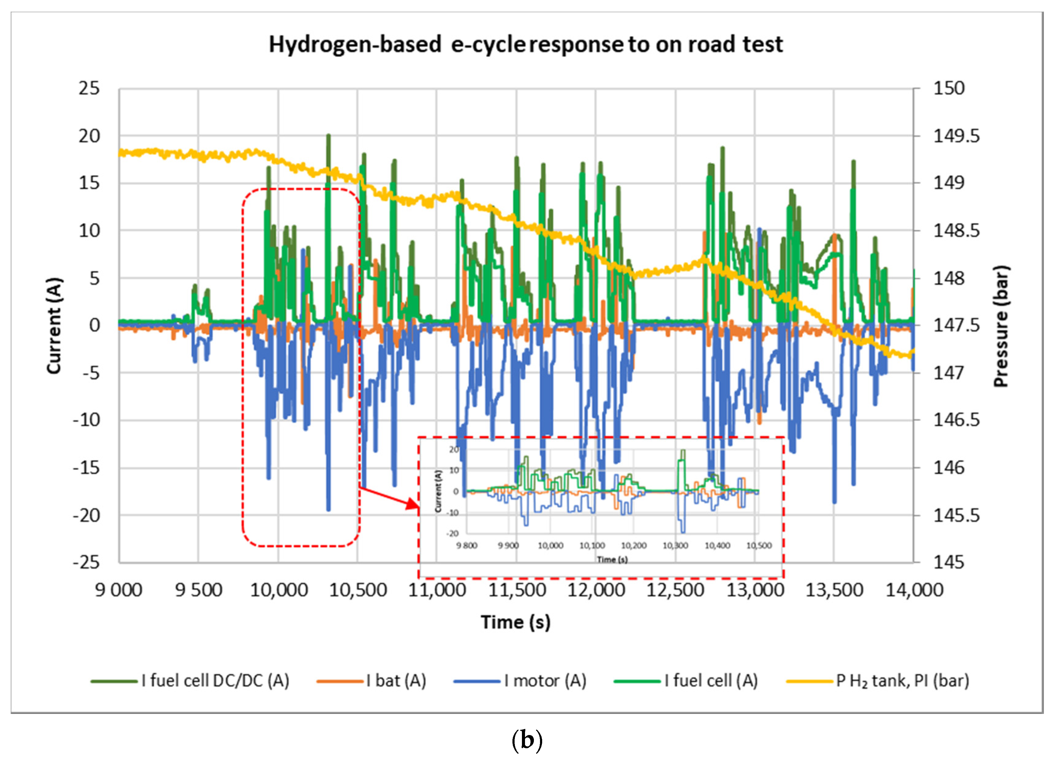
The last test consisted of an on-road dynamic test to assess the capability of the designed powertrain in meeting the requirements of a real driving profile,
Figure 10.
In this test, the hydrogen-based powertrain was subjected to sudden changes in the driving profile. Note that the fuel cell provided almost all the current while the battery filtered instabilities and provided current peaks. Battery SOC started at 93%, as it was continuously charging, meanwhile it did not provide the required current peaks. When motor current peaks needed to be provided by the battery, its SOC decreased instantaneously. Hydrogen pressure in the storage tank reduced and can be measured to later estimate the autonomy of the system. Overall, the fuel cell responded with enough power to meet the motor demand and to charge the battery, validating the hybrid design along the buffer battery.
3.3. Temperature Test
During the on-road tests of the hybridized hydrogen-based unipersonal electric vehicle, it was verified that the temperature remained in an adequate range, with the corresponding increase in the fan speed for cooling during higher peaks of current supplied by the fuel cell. Although the system guarantees good cooling, it is interesting to consider innovative solutions in battery cooling [
36] to scale the hybrid propulsion system to higher power developments. The temperature evolution during on-road test according to the current and the fan interaction is verified in
Figure 11.
3.4. On-Road Autonomy Test
The on-road autonomy test covered a total of 48 km at an average speed of 12 km/h. The unipersonal electric vehicle was first operated with battery-based powertrain and then with hydrogen-based powertrain, on a bicycle path, from INTA facilities to the town of Mazagón. Taking into account the hydrogen-based system, initially the hydrogen pressure tank achieved 350 bar. At the end of the test, pressure was reduced 68 bar. Using the Redlkich–Kwong equation of state [
37], a hydrogen consumption of 26.5 g was obtained, assuming that the tank was at 25 °C during the entire test. This resulted in an energy consumption of 1044 Wh (HHV). On the other hand, according to
Table 5,
Section 2.3, the total amount of energy available in hydrogen-based system was 6294 Wh (HHV), and 266 Wh in battery-based system. This means there was a maximum autonomy of 290 km for the hydrogen-based system while just 15 km for the battery-based system.
4. Discussion
This section presents an analysis of the main results obtained in the tests. Both battery-based and hydrogen-based unipersonal electric vehicles developed in this work have been exposed to real laboratory and on-road driving test conditions, according to the urban mobility conditions for which they have been developed.
4.1. Battery-Based System Response
The battery system has a direct energy exchange between the motor demand and the battery supply. In this way, as the motor accelerates, it demands more electrical current, supplied directly from the electrical energy stored in the battery. This causes a reduction in the battery SOC and, thus, the battery voltage. The system limits its flexibility to that provided by the characteristics of the battery. Therefore, for a battery-based unipersonal electric vehicle, it must be scaled based on the selected battery since the entire propulsion system—acceleration, autonomy, recharging, etc.—is directly linked to the battery selection.
4.2. Hydrogen-Based System Response
In the hydrogen-based hybrid system, in response to the demand of the motor, there is a stabilized supply from the fuel cell, through its DC/DC converter. In this system, the battery acts as a buffer, providing current and energy, in cases where the fuel cell is not able to supply instantaneous high current demand peaks from the motor. Slow motor demand transients can be supplied by the fuel cell. In short transient demand peaks, the battery supplies the necessary current. Likewise, the battery undergoes instantaneous SOC decreases, which are recovered in the next driving step. Regarding the hydrogen consumption, it also decreases the pressure in the hydrogen tank as it is consumed by the fuel cell for the electricity production. Therefore, the system shows an energy flexibility scalable to the supply capacity of the hydrogen system. The greater the storage tank capacity, the greater the autonomy, the larger the fuel cell and its converter, and the more energy that can be supplied directly. Power flexibility depends not only on the hydrogen system, but also on the buffer battery. Once it has been verified that it provides the current peaks demanded by the motor, it must be scaled based on the corresponding urban mobility application.
5. Conclusions
In this work, a test platform was built to establish a comparison between a unipersonal electric vehicle powered only by batteries, and the same one powered by a hybrid system based on hydrogen and batteries. Both systems had similar weight. In this way, it is possible to compare both technologies, their advantages and disadvantages, in the same platform. The autonomy of the hybrid hydrogen-based system was 290 km, being much greater than that of the battery-based system that reached approximately 15 km. Preliminary conclusions allow us to recognize that energy hybridization provides great specific advantages to urban mobility applications. Indeed, the improvements can be quantified as an increase of 1790% in specific energy and 335% in energy–volume relation. The results show that the unipersonal electric vehicle equipped with a hydrogen-based powertrain provides not only greater autonomy, but also has shorter recharge times.
The capacities obtained in terms of autonomy, recharging time and, above all, environmental advantages regarding the reduction in pollutants, make this a promising and scalable proposal for use in sustainable cities.


 ,
, 


