
Interval Type-2 Fuzzy Logic Anti-Lock Braking Control for Electric Vehicles under Complex Road Conditions


1
Faculty of Mechanical Engineering and Automation, Zhejiang Sci-Tech University, Hangzhou 310018, China
2
School of Mechanical and Electrical Engineering, Wenzhou University, Wenzhou 325035, China
*
Author to whom correspondence should be addressed.
Sustainability 2021, 13(20), 11531; https://0-doi-org.brum.beds.ac.uk/10.3390/su132011531
Submission received: 9 September 2021
/
Revised: 13 October 2021
/
Accepted: 14 October 2021
/
Published: 19 October 2021
(This article belongs to the Special Issue Intelligent Technologies in Energy Management of New Energy Vehicle)
Abstract
:To simultaneously track the ideal slip rate and realize ideal energy recovery efficiency under different complex road conditions, an electro-hydraulic compound anti-lock braking system based on interval type-2 fuzzy logic control strategy and its corresponding braking torque allocation strategy have been developed for electric vehicles. The proposed interval type-2 fuzzy logic controller aims to calculate the ideal total braking torque by four steps, namely, fuzzification, fuzzy inference, type reduction, and defuzzification. The slip rate error and the change rate of slip rate error are utilized as inputs in the fuzzification, and then, the membership degree interval of fuzzy variables determined by the upper and lower membership functions is used to calculate the activation degree interval of different fuzzy rules in the fuzzy inference process, which enhances the anti-interference ability to external uncertainties and internal uncertainties. The braking torque allocation strategy is proposed to maintain the maximum energy recovery efficiency on the premise of safe braking. The software of MATLAB/Simulink is applied to simulate the process of anti-lock braking control under two complex road conditions. Simulation results corroborate the proposed interval type-2 fuzzy logic anti-lock braking control system can not only obtain better slip rate control effect and outstanding robustness but also achieve ideal regenerative braking energy recovery efficiency under both joint-μ and split-μ road surfaces.
1. Introduction
In the face of the problems of environmental pollution and energy shortage, electric vehicles (EVs) have become the main development direction of the automotive industry [1]. Taking advantage of both regenerative braking subsystem in braking energy recovery and traditional hydraulic braking subsystem in high power density, the electro-hydraulic compound braking system has great potential to make a trade-off between energy saving and braking control effect for EVs [2]. With the increase of both driving velocity and driving condition complexity of EVs, the anti-lock braking system (ABS) is regarded as one of the necessary auxiliary systems of electric vehicles to decline the rate of traffic accidents. A cooperative control algorithm for electric vehicles was proposed to improve the ABS working performance [3]; additionally, a nonlinear model predictive control was used on ABS and tested on a high-end vehicle simulator to verify the performance and robustness of the ABS controller [4]. Compared with traditional vehicles, the EVs can implement regenerative braking technology to enhance energy utilization efficiency by recovering kinetic energy during the braking process [5]. Thus, the anti-lock braking function of EVs can be done by the electro-hydraulic compound braking system to make a trade-off between the energy saving and anti-lock braking control effects.
The ABS control strategy can be regarded as one of the main key technologies for EVs to realize the anti-lock braking function, which is used to calculate the demand braking torque of every wheel [6]. At present, some traditional control algorithms have been widely applied in designing the vehicle ABS controller, which is mainly including logic threshold control, proportion integral differential (PID) control, and sliding mode control. Chiang et al. [7] proposed a logic threshold ABS control system to realize the anti-lock control function by constraining the motor reference torque with an allowable value. Yang et al. [8] designed a logic threshold control with phase plane theory to analyze the relation between slip rate and braking torque, and then, the composition rule of expected braking torque was studied to improve the anti-lock braking control effect. However, by analyzing these ABS control strategies on the basis of the logic threshold control method, it can be seen that the rule database for various road conditions is difficult to be established. Feng proposed the discrete fuzzy adaptive PID to accurately track the ideal wheel slip rate [9]. Moreover, to enhance the robustness of a control system regardless of system parameter variations, sliding mode control is still widely applied in ABS control. Sun et al. [10] investigated a sliding mode wheel slip rate control to yield anti-lock control of wheels with an adaptive sliding surface, and Rahul et al. [11] proposed a multiple surface sliding controller to maintain the optimal slip rate in unknown road surface conditions. However, note that the common sliding mode ABS controller is always robust but not optimal. In summary, the control effects of traditional control algorithms always depend on the accuracy of mathematic modeling. Due to the massive nonlinear, time-varying and lagging influencing factors in the anti-lock braking control process, the mathematical dynamics model of ABS is difficult to be accurately described, especially for EVs.
With the rapid development of intelligent technology, intelligent control algorithms have great advantages, which mainly include fuzzy control [12], neural network [13], and genetic algorithm [14]. Due to a large number of nonlinear, time-varying, and hysteretic factors in the process of vehicle ABS control, the ABS control model is difficult to be accurately described. Therefore, fuzzy control, which does not depend on the precise mathematical model of the controlled object, has been widely studied by experts and scholars. Fargione et al. [15] proposed a fuzzy control strategy integrated optimization of genetic algorithm to realize the anti-lock braking function of the electro-hydraulic braking system. Andrei et al. [16] improved the vehicle braking stability and regenerated the maximum possible amount of energy by designing a fuzzy control algorithm on the basis of road recognition. Mokarram et al. [17] studied a fuzzy logic controller in 0.35 μm standard complementary metal oxide semiconductor (CMOS) process and used adaptive neural-fuzzy inference systems of software to define the parameters of the fuzzy logic controller; the simulation results show the controller have a high speed of calculation and low power consumption in ABS. However, the proposed controller lacks adaptive ability because the fuzzy logic parameters are invariable. In summary, the shape of the membership function and the corresponding membership degree of each point in the domain for the fuzzy logic control algorithm mentioned above are determined, so it can be collectively referred to as ‘type-1 fuzzy logic control’. However, the shape of the membership function and the membership degree corresponding to each point in the domain are single and invariable in the type-1 fuzzy logic controller. Moreover, in the process of EVs anti-lock braking control, the information of different road adhesion coefficient and optimal slip rate has strong uncertainty, and the type-1 fuzzy logic control is lack of adaption for environmental variation with more uncertain information. Therefore, the type-1 fuzzy logic control has unsatisfactory performance in tracking optimal slip rate and energy recovery when road surface abruptly changed or the EVs wheels braking on different road surface respectively.
On the basis of the traditional fuzzy set, the type-2 fuzzy set has carried on the expanded dimension processing. A single fuzzy variable is described by two different levels of membership function, which can simultaneously mode both intra-personal uncertainty and inter-personal uncertainty [18,19]. Hence, in many applications, such as system controlling, decision making, and machine learning, the type-2 fuzzy control algorithm have been demonstrated better performances compared with the traditional type-1 fuzzy control. Claudia I et al. [20] proposed a generalized type-2 fuzzy logic system with the limitation of complexity by the theory of alpha-planes. Zhang [21] used trapezoidal interval type-2 fuzzy sets to investigate the multiple attribute group decision-making problems. Gaxiola [22] et al. used an improved type-2 inference system to estimate the type-2 fuzzy weights of backpropagation neural network, and the simulation results illustrate the advantages of the bio-inspired methods optimizing type-2 fuzzy systems. Sanchez et al. [23] used a mobile robot in conjunction with three types of external perturbations to contrast the control performance of generalized type-2 fuzzy systems and interval type-2 fuzzy systems and type-1 fuzzy systems; the results show the type-2 fuzzy logic control has better anti-interference ability than type-1 fuzzy logic control. It is noted that there has been no research about the ABS control method based on type-2 fuzzy logic algorithm until now. The possible reasons are that the computing process is complex and time-consuming, which is unfit for the time-varying ABS model, and the fuzzy rules are difficult to be formulated without sufficient experience.
This present study aims to fulfill the excellent optimal slip rate tracking effect under complex road conditions by introducing an electro-hydraulic compound anti-lock braking control system. The proposed anti-lock braking control system utilizes an interval type-2 fuzzy logic algorithm to calculate the expected braking force tracking ideal slip rate, which differs from conventional type-1 fuzzy logic control. The membership degrees of fuzzy variables in different fuzzy sets of conventional type-1 fuzzy logic are constant, which reduce the anti-interference ability of the controller, resulting in unsatisfactory performance of slip rate control when the working conditions are variable. The proposed control algorithm utilizes upper and lower membership functions to describe the membership degree of fuzzy variables so that the anti-interference ability and adaptation of the controller can be enhanced when external conditions are changing.
This research considers the following contributions:
- (1)
- The structure composition and operating principle of the proposed interval type-2 fuzzy logic electro-hydraulic compound anti-lock braking system is given out in detail, and the allocation strategy is designed by considering the balance between the energy recovery efficiency and braking safety.
- (2)
- Considering the uncertain road conditions of anti-lock braking control, the single fuzzy variable is described by membership function of two different levels by using the membership function expansion method and set the secondary membership degree of fuzzy variable to a constant value of 1 to enhance the ability of anti-interference for fuzzy control under massive uncertainty information during the braking process, and Karnik–Mendel (KM) algorithm fuzzy type reduction method is adopted to solve the complex calculation problem of generalized type-2 fuzzy reasoning.
2. System Model
2.1. Dynamic Model of Automobile Brake System
Establish the vehicle coordinate system consolidated to the center of mass, with the x-axis pointing forward parallel to the ground, the y-axis pointing forward parallel to the driver’s left, and the z-axis pointing upward through the center of mass.
Ignoring the dynamic effects of suspension, the vehicle only moves parallel to the ground, and ignoring the changes in tire characteristics caused by load changes of left and right tires and the effect of tire righting torque, the vehicle is simplified to the dynamic model [24,25] shown in Figure 1.
The equation of motion of the electric vehicle is expressed as follows:
where m is the mass of the electric vehicle; vx, vy, , and represent the velocity and acceleration of electric vehicle along the x- and y-axis, respectively. β is the angle between the air resistance and the driving direction. FD illustrates the air resistance. γ, , and Iz are the vehicle’s yaw angle, yaw angular velocity, and moment of inertia around the z-axis, respectively. la and lb are the distances between the mass center of the vehicle and the front and rear axles, respectively. tf and tr indicate, respectively, the front and rear wheelbases. , , and stand for the moment of inertia, angular velocity, and angular acceleration of the wheel, respectively. , , and are the wheel driving torque, braking torque, and rolling resistance torque, respectively. is the rolling radius of the wheel. and are the longitudinal force, lateral force, and steering angle of the wheel, respectively. The subscript i are 1, 2, 3, and 4, indicating the front right wheel, front left wheel, rear right wheel, and rear left wheel, respectively.
2.2. Tire Model
The Magic Formula tire model [26] is used to describe the dynamic behavior of vehicle.
where Y is the output variable, namely longitudinal force; λ is the slip rate of the electric wheel; B, C, and E represent the stiffness, shape, and curvature coefficients, respectively; D is the peak value; SH and SV stand for the horizontal and vertical biases, respectively.
The slip rate of the electric wheel is defined as follows:
2.3. Hydraulic Braking System Model
The typical dynamic model of ABS hydraulic system is described as follows [27]:
where Pm, Pw, and Pr are the pressure of the main cylinder, wheel cylinder, and low-pressure accumulator, respectively; Ce is the equivalent liquid capacity characteristic coefficient of the pipeline and wheel cylinder; Re and are the equivalent liquid resistance characteristic coefficient of the pipeline and wheel cylinder when the pressure is increased and reduced, respectively; and are the transmission lag time of solenoid valve and pipeline during pressurization and decompression, respectively; u1 and u2 are the control command signal of solenoid valve:
Considering the influences of oil pressure, friction coefficient, temperature, and other factors, the first-order inertia link is used to represent the time delay in the process of applying brake pressure to the actual braking torque output:
where P(s) and P0(s) are the actual and target oil pressure of the brake, respectively; τ is a constant reflecting the dynamic characteristics of the brake.
The hydraulic braking torque Th produced by the brake can be written as follows:
where Af indicates the area of the brake wheel cylinder piston. μb represents the friction coefficient; η is wheel cylinder efficiency, and Rb stands for the effective radius of friction.
2.4. Regenerative Braking Dynamics Model
In this research, the front and rear wheels of the electric vehicle are equipped with an in-wheel motor which can drive/brake independently of each other. The type of the in-wheel motor is set as the permanent magnet synchronous motor (PMSM), and the mathematical model of the motor is expressed as follows:
where ud and uq are the voltage of d and q axes, respectively; id and iq indicate the current of d- and q-axis, respectively; Ld and Lq represent the inductor of d- and q-axis, respectively; p is the number of pole-pairs; ψf illustrates the motor magnetic chain; ωd is the rotor angular velocity of the motor, and Tr is the braking torque of the motor.
The in-wheel motor is adopted with a round rotor structure, and the Ld equals to Lq, which means the Tr can be simplified as follows:
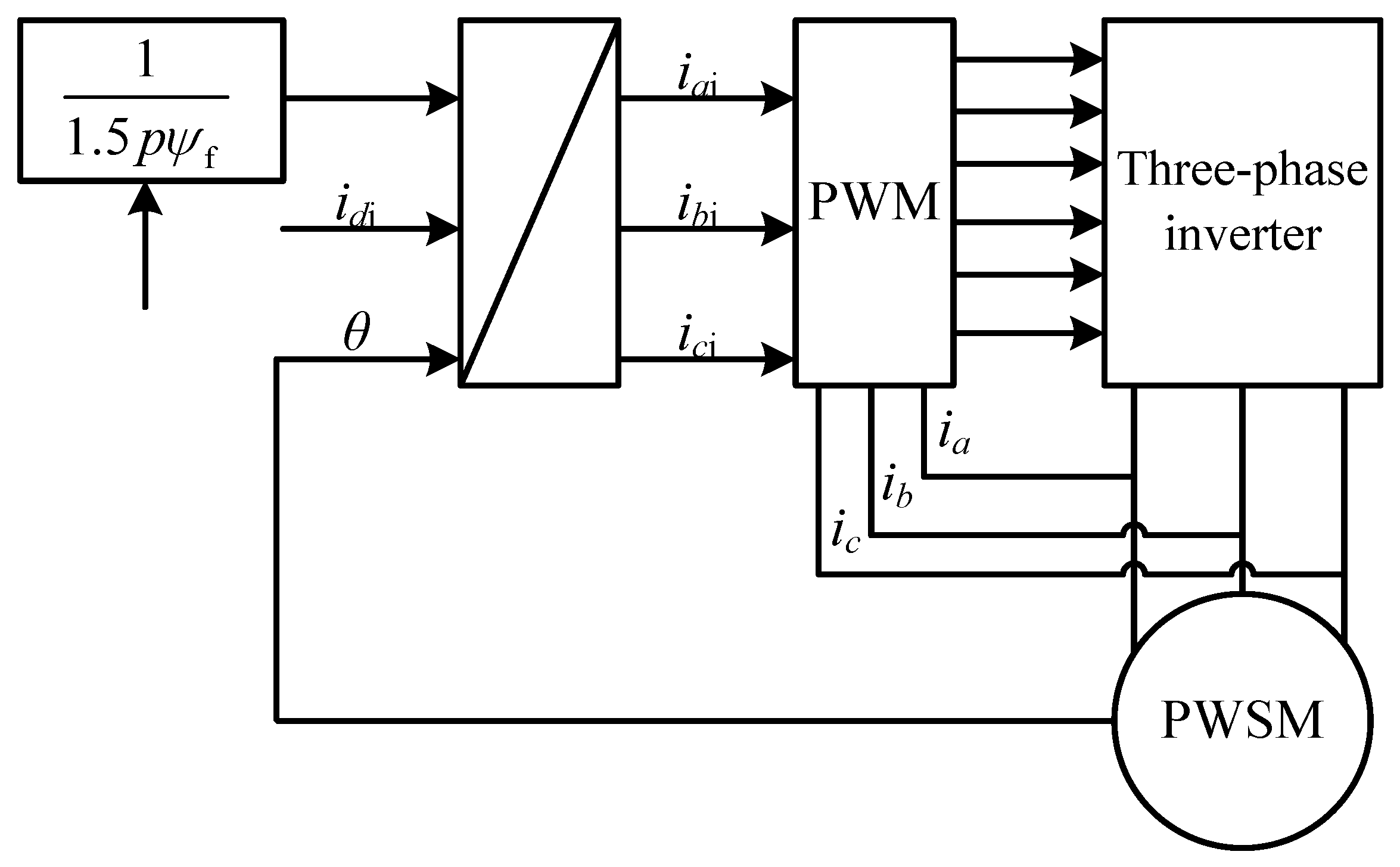
Thus, the braking torque of the motor can be gained by controlling the iq of q-axis. The tracing torque control theory of PMSM’s can be described in Figure 2. The θ is the rotation angle of rotor, the iqi and idi are the expected current of q- and d-axis, respectively; the iai, ibi, and ici are the expected currents of phase a, b, and c, respectively; ia, ib, nd ic are the actual currents of phase a, b, and c, respectively.
The coordinate transformation formula of three-phase expected current iai, ibi, and ici is described as follows:
Input the respective different values between iai, ibi, and ici and ia, ib, and ic into the hysteresis current control unit to get the control switch signals of six switching devices of the three-phase inverter, and then control the switch on and off. Finally, torque tracking control of the PMSM motor is realized.
3. Design of Interval Type-2 Fuzzy Logic Anti-Lock Braking Control System
3.1. Overview of Interval Type-2 Fuzzy Logic Control Strategy
Type-2 fuzzy set is an extension of type-1 fuzzy set, which has larger membership space, better anti-interference ability, and accurate ability of fuzzy logic to approximate unknown function when dealing with highly uncertain information. The type-2 fuzzy set can be described as follows [28]:
where x and u are respectively the first and second variables of the type-2 fuzzy set; Jx and are respectively the primary and secondary membership degree.
The membership function of the type-2 fuzzy set is composed of upper membership function (UMF) and lower membership function (LMF), and the corresponding relationships are shown in Figure 3.
The interval type-2 fuzzy set is a special case of type-2 fuzzy set where the secondary membership degree of variable x is identically equal to 1 and can be described as follows:
Since the secondary membership degree of fuzzy variables in the interval type-2 fuzzy set is always equal to 1, the problem of massive calculation in the process of type-2 fuzzy inference can be avoided, which means the results of fuzzy inference can be obtained quickly. At the same time, the description of the uncertainty between individuals in the uncertainty domain composed of the upper and lower membership functions of fuzzy variables enhances the ability of fuzzy logic to model the anti-lock braking system and the adaptability of the fuzzy logic to different external disturbances such as the abrupt change of road adhesion coefficient and the optimal slip rate, and the interval type-2 fuzzy logic has the advantage of the uncertainty processing ability to generalize type-2 fuzzy logic. Therefore, for the characteristics of complex, dynamic, nonlinear, time-varying, and parameter uncertainty of the anti-lock process in emergency braking, interval type 2 fuzzy logic has better anti-lock braking control potential.
3.2. Design of Interval Type-2 Fuzzy Logic Anti-Lock Braking Control System
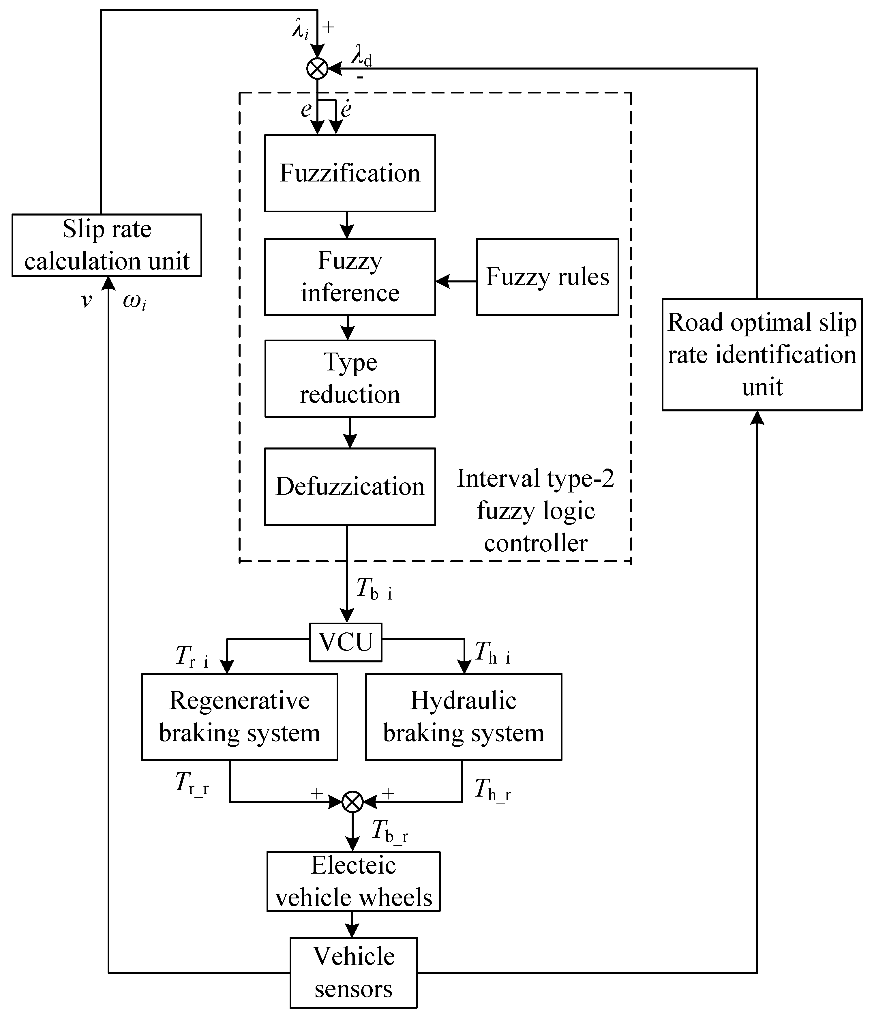
The working principle of an electro-hydraulic compound anti-lock braking system is to track the ideal slip rate λd by controlling the longitudinal slip rate of the wheel and make the fluctuation near the value of the ideal slip rate. The working principle of the designed interval type-2 fuzzy logic electro-hydraulic compound anti-lock braking control system is shown in Figure 4.
As shown in Figure 4, the interval type-2 fuzzy logic electro-hydraulic compound anti-lock braking control system is mainly composed of the interval type-2 fuzzy logic controller, slip rate calculation unit, ideal slip rate identification unit, vehicle control unit (VCU), regenerative braking system, hydraulic braking system, electric vehicle wheels, and vehicle sensors.
The interval type-2 fuzzy logic controller takes the difference value e = λ − λd between the wheel actual slip rate and the ideal slip rate and its change rate as inputs and then calculates the ideal anti-lock braking torque Tb_i through four steps, which include fuzzification, fuzzy inference, type reduction, and defuzzification. Then, it outputs the calculation results into VCU. VCU sends signals to the regenerative and hydraulic braking systems to generate the regenerative and hydraulic braking torque on the wheels. The wheel angular velocity and vehicle velocity are detected by the vehicle sensors, and vehicle sensors output the result into the slip rate calculation unit and ideal slip rate identification unit. The slip calculation unit and the ideal slip rate identification unit outputs the wheel slip rate λi and the ideal slip rate λd to interval type-2 fuzzy logic controller, respectively.
The specific design steps of interval type-2 fuzzy logic electric-hydraulic compound anti-lock braking controller are described in detail as follows:
Step 1: fuzzification
The Mamdani type is adopted in the proposed interval type-2 fuzzy logic controller. The difference value of the wheel slip rate and the ideal slip rate e = λ – λd and its change rate are token as the input variables, and the ideal anti-lock braking torque Tb_i is the output variable.
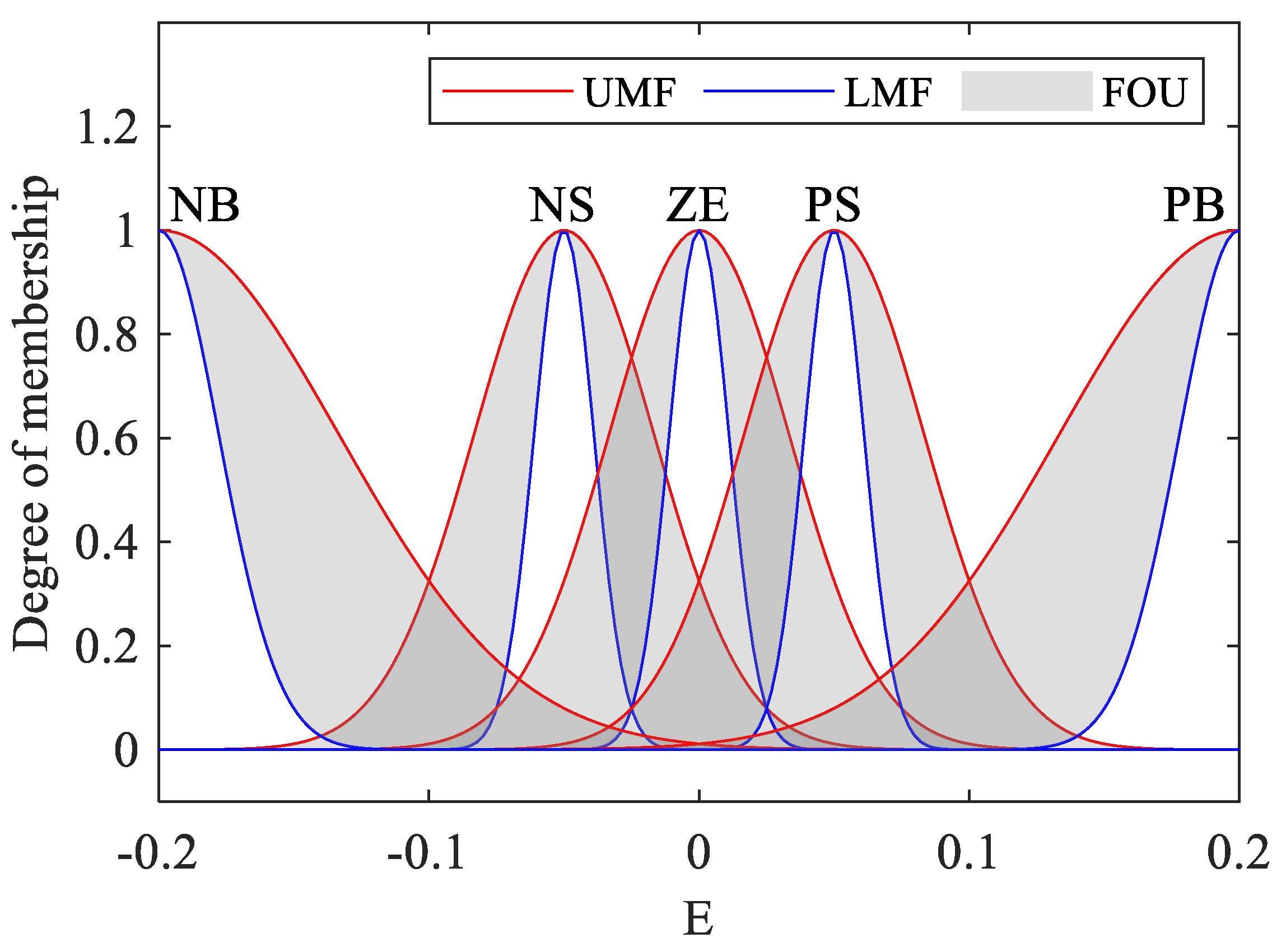
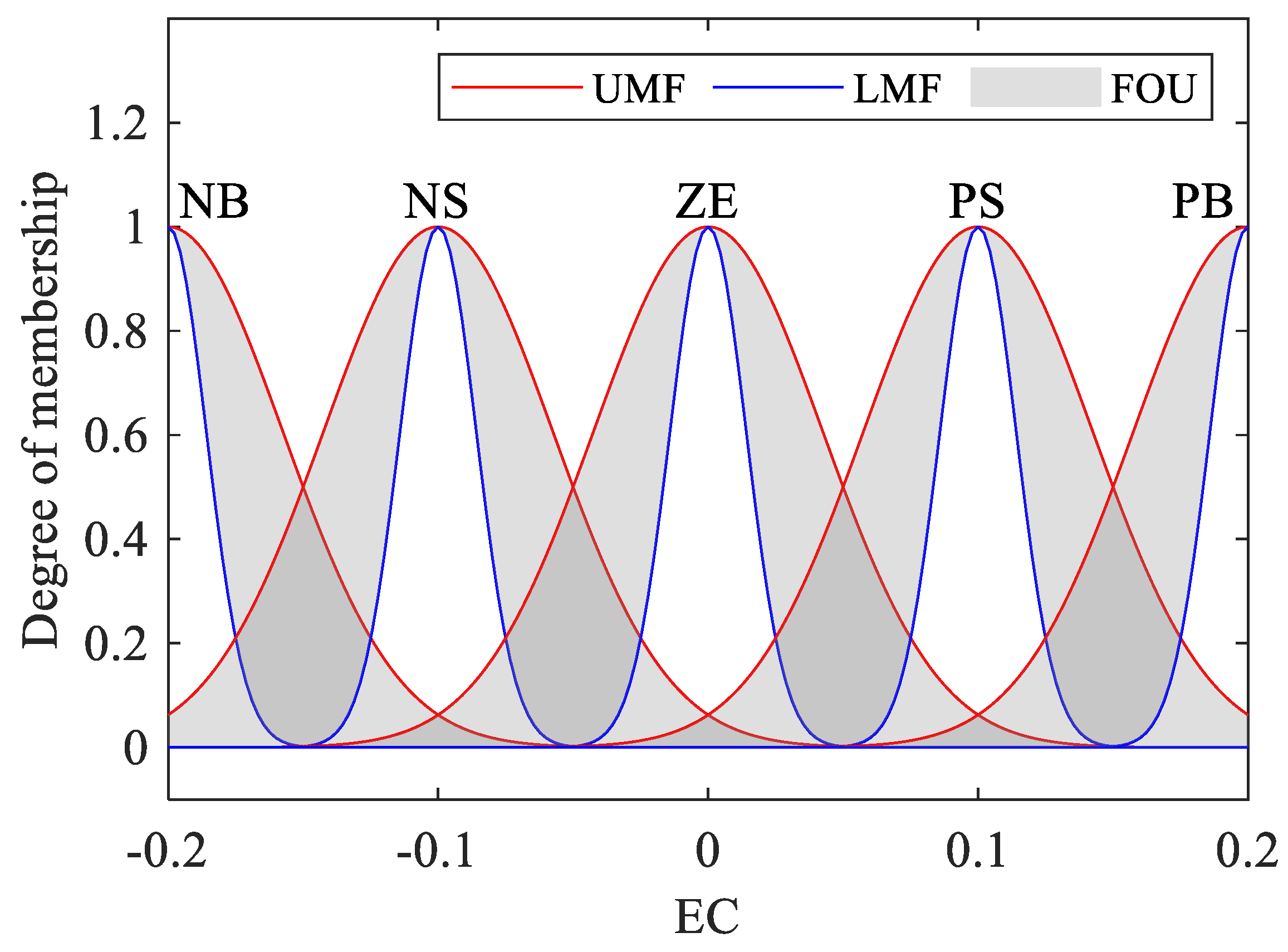
The type-2 fuzzy set of e is = {NB, NS, ZE, PS, PB}; the subscript m values are 1, 2, 3, 4, AND 5, which stands in order for a subset of the type-2 fuzzy set. The type-2 fuzzy set of is = {NB, NS, ZE, PS, PB}; the subscript n values are 1, 2, 3, 4, and 5 and respectively stand in order for a subset of the type-2 fuzzy set. NB, NS, ZE, PS, and PB represent the negative big, negative small, zero, positive small, and positive big, respectively.
The type-2 fuzzy set of Tb_i is = {SR, SM, MI, BI, BR}; the subscript k values are 1, 2, 3, 4, and 5 and respectively stand in order for a subset of the type-2 fuzzy set. SR, SM, MI, BI, and BR indicate the smaller, small, middle, big, and bigger, respectively.
The upper and lower membership functions of inputs and output are gaussmf, expressed as follows:
where c determines the center position of the function; σ determines the width of the curve of the function.
Figure 5, Figure 6 and Figure 7 illustrate the shape of the membership function of the input variables and output variable.
.
Step 2: fuzzy inference
The purpose of anti-lock braking control is to control the wheel slip rate tracking the ideal slip rate. Therefore, when the different e between the wheel slip rate and the ideal slip rate is negative and the absolute value is large, the ideal anti-lock braking torque Tb_i should be increased to increase the real braking torque. Therefore, the wheel slip rate increases and approaches the ideal slip rate. On the contrary, when the difference e is positive and the absolute value is large, it is necessary to reduce the real braking torque, so that the decreased wheel slip rate is close to the ideal slip rate. Therefore, the interval type-2 fuzzy logic control rule is: if e is and is , then Tb_i is .
Table 1 shows the designed fuzzy control rules.
The calculation process of interval type-2 fuzzy controller is described as follows:
- (1)
- Calculate the membership interval of the fuzzy input variable e and the membership interval of the fuzzy input variable .
- (2)
- Calculate the activation degree interval Fmn (e,) of each rule. The computational formula is as follows:where is the lower edge of the activate interval for the number mn rule; is the upper edge of the activate interval for the number mn rule. “” stands for the minimum value t-norm.
Step 3: type reduction
The activation degree interval of each rule is integrated with the membership function of the output variable, and the KM algorithm [29] is used to simplify the type of fuzzy set output obtained by integrated. The result of fuzzy inference can be expressed as
where Tb_il and Tb_ir represent the left and right endpoints of the interval type-2 fuzzy set output; f and g are the upper and lower bounds of the interval type-2 fuzzy output interval in the fuzzy set domain, respectively; L is the left transition point, and R is the right transition point.
Step 4: defuzzification
The final ideal anti-lock braking torque Tb_i can be calculated as follows:
3.3. Allocation Strategies of Anti-Lock Braking Wheel Cylinder Pressure
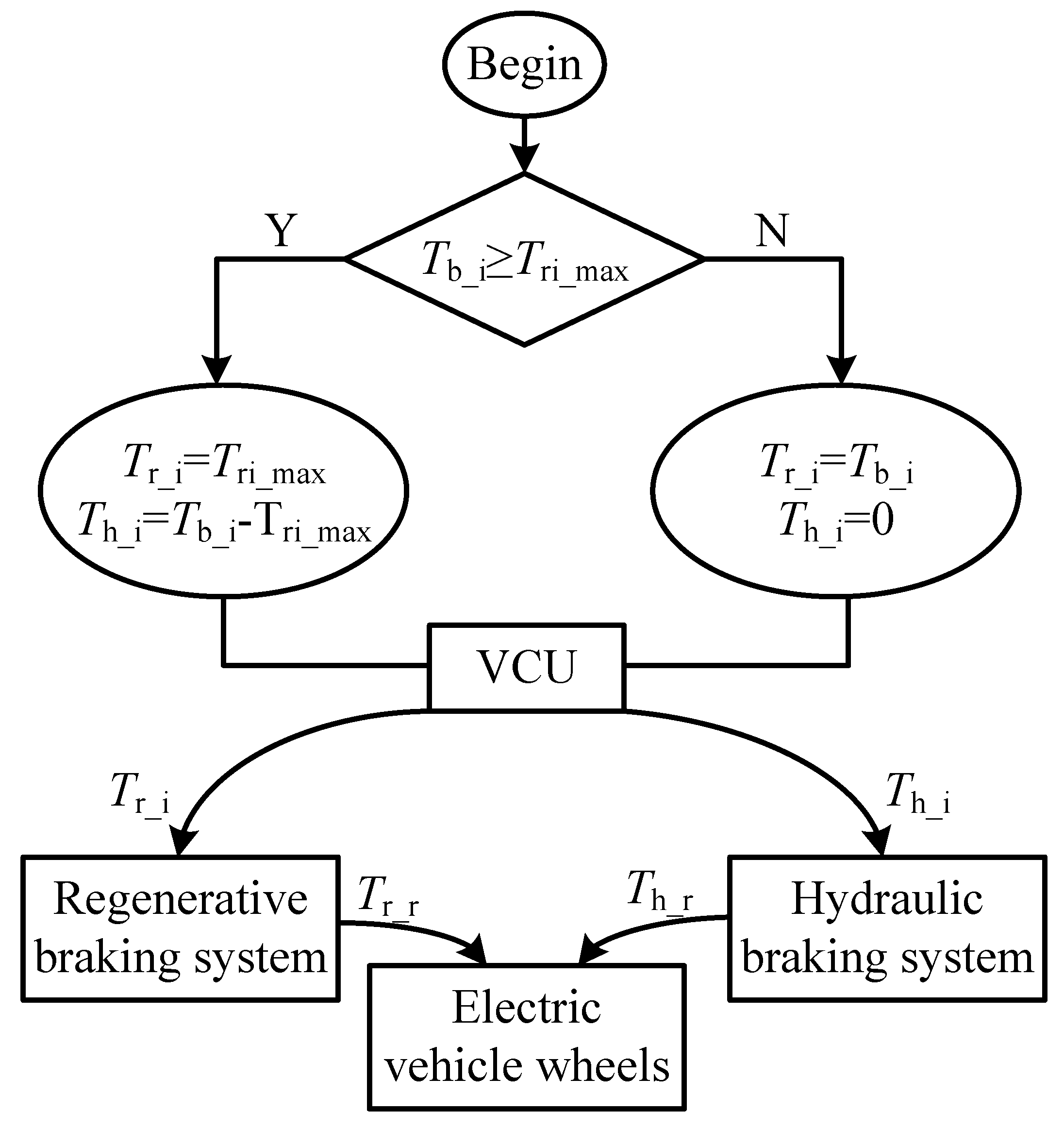
In this study, the electro-hydraulic compound anti-lock braking control aims to realize the maximum energy recovery efficiency on the premise of safe braking, so the ideal anti-lock braking torque Tb_i should be ensured that the regenerative braking torque is always equal to the maximum energy recovery regenerative braking torque Tri_max and the rest braking torque provided by hydraulic braking system under every kind of braking conditions except when the ideal anti-lock braking torque Tb_i is smaller than the motor’s maximum energy recovery regenerative braking torque Tri_max. Furthermore, when the ideal anti-lock braking torque Tb_i is smaller than the maximum energy recovery regenerative braking torque Tri_max, the pattern of braking is switched from composite braking to pure regenerative.
The proposed allocation strategies flowchart is described in Figure 8.
VCU adjusts the liquid output solenoid valve current of the wheel cylinder according to Equation (18) based on the difference between ideal hydraulic braking torque Th_i and the real hydraulic braking torque Th_r.
Thereby, the VCU controls the regenerative braking system working according to the ideal regenerative braking torque Tr_i and produces real regenerative braking torque Tr_r.
4. Simulation Results and Discussion
In this section, simulations are conducted to demonstrate the control effects of the proposed electro-hydraulic compound anti-lock braking control on the basis of interval type-2 fuzzy logic anti-lock braking control method. The MATLAB/Simulink software is widely used to simulate the real process of car driving [30]. Table 2 shows the main parameters of the electric vehicle.
To verify the effectiveness of the proposed interval type-2 fuzzy logic control, the braking performance is compared using two controllers as follows:
Electro-hydraulic compound anti-lock braking controller 1: the controller is applied with an interval type-2 fuzzy logic control algorithm.
Electro-hydraulic compound anti-lock braking controller 2: the controller is applied with a type-1 fuzzy logic control algorithm.
The initial vehicle velocity is set to 108 km/h. The ABS control quit to work and increase the braking torque to a certain value to make the wheels locked when the vehicle velocity decelerates to 10 km/h. Furthermore, the control precision of slip rate utilizes the root-mean-square (RMS) of slip rate error to be quantified. The error is defined as follows:
where indicates the error of slip rate.
Two working conditions are simulated in this research to demonstrate the control effects of the interval type-2 fuzzy logic anti-lock braking control method.
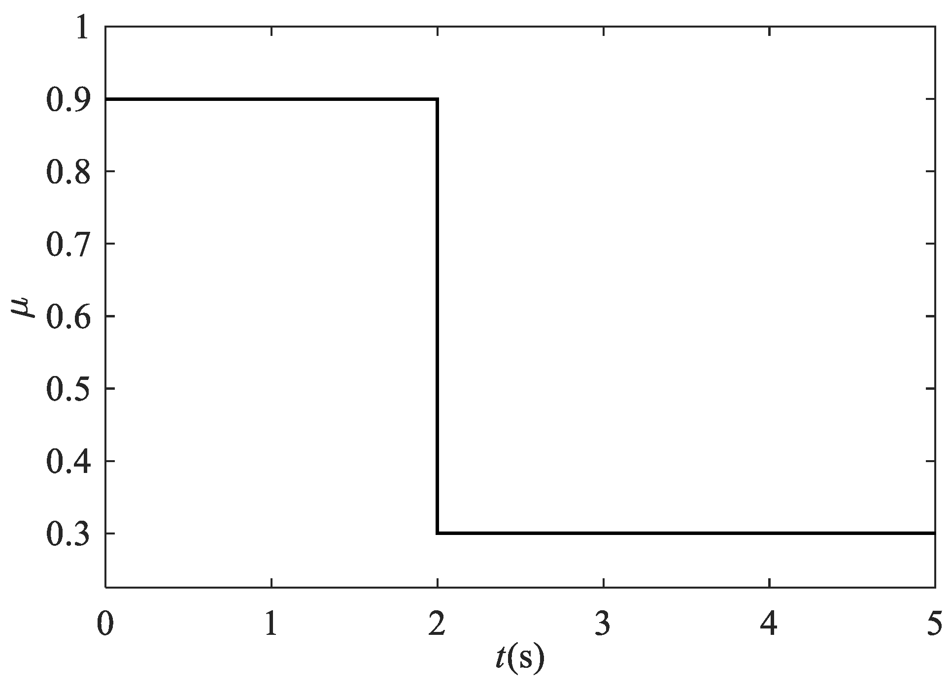
Working condition 1: the joint-μ road, which means the road peak friction coefficient suddenly changed from the high value to low value at 2 s, which is referenced from [31].
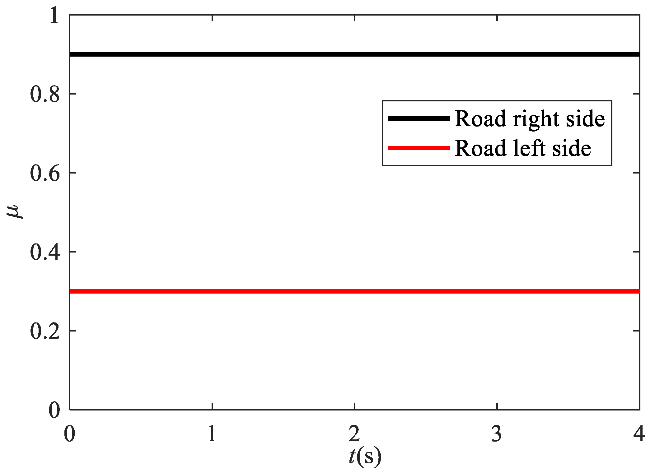
Working condition 2: the split-μ road, which means the left side of the road is dry with the high friction coefficient and the right side is snow with a low coefficient, which is referenced from [32].
4.1. Braking Performance Comparison under the Joint-μ Road Surface
Figure 9 shows the curve for the change of road peak adhesion coefficient μ. The μ alters from 0.9 of dry road to 0.3 of snow road at 2 s.
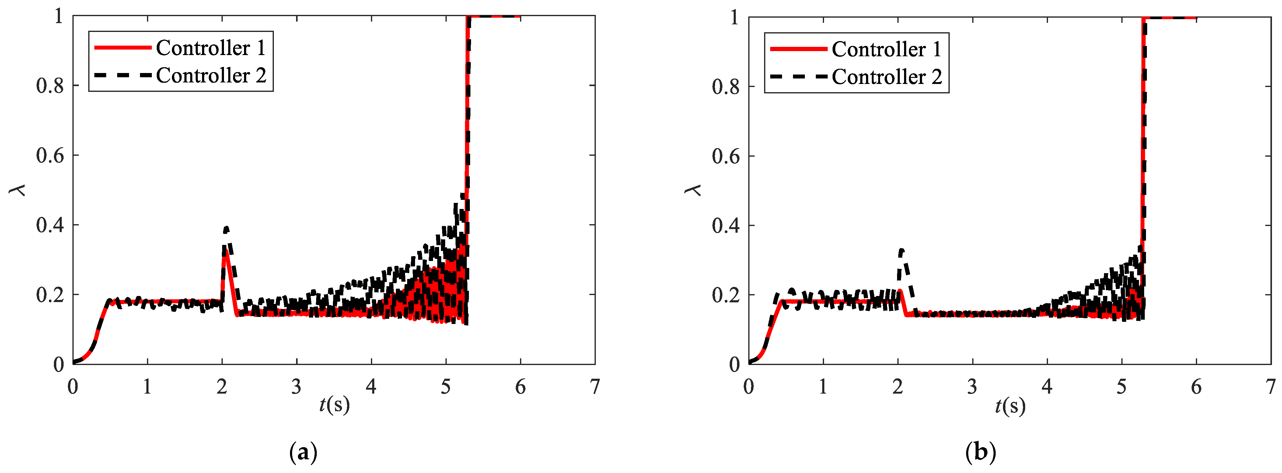
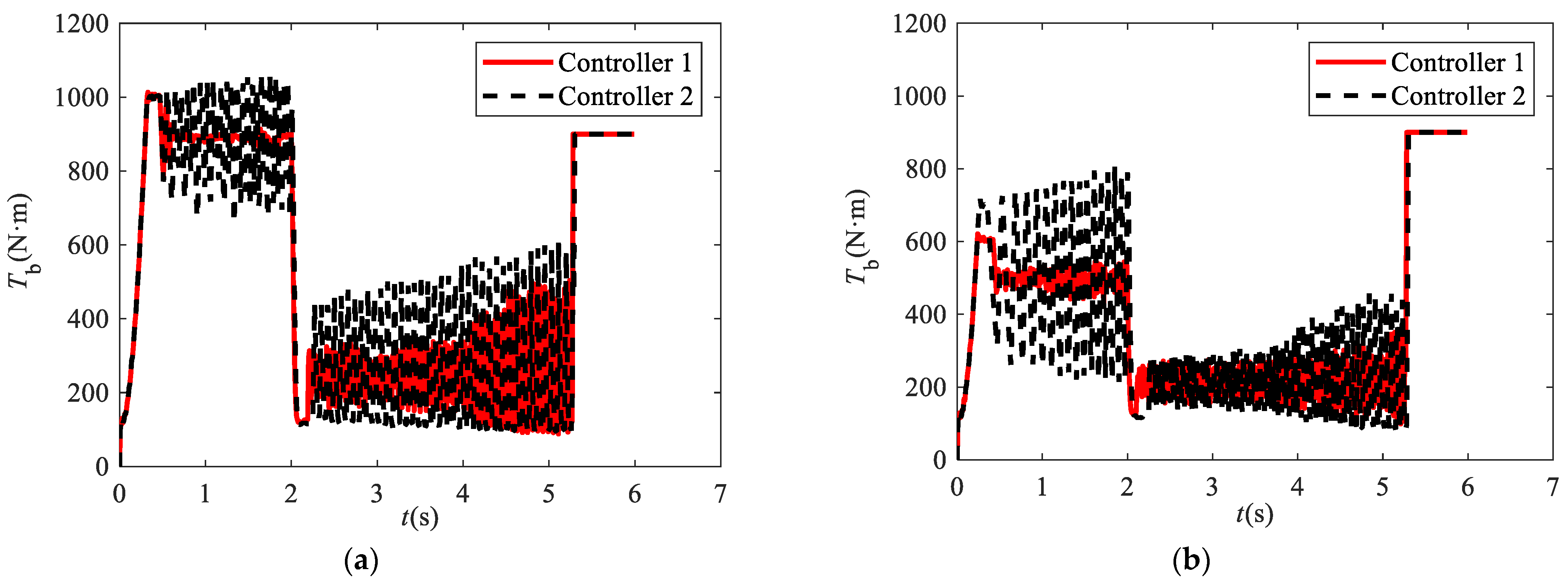
Figure 10, Figure 11 and Figure 12 exhibit the comparison curves of slip rate, total braking torque, regenerative braking torque, hydraulic braking torque, and velocities under condition 1.
As shown in Figure 10, the RMS of slip rate error of front and rear wheels with controller 1 are reduced by 54.44% and 57.28% compared to controller 2, respectively, which illustrates the control effects of the proposed interval type-2 fuzzy logic strategy with the change of peak adhesion coefficient have smaller fluctuations than type-1 fuzzy logic. Moreover, there is an abrupt jitter at 2 s where the road surface changed for both two controllers, but the degree of jitter of controller 1 is lower than controller 2, which indicates the slip rate control transition of interval type-2 fuzzy control is more stable than type-1 fuzzy logic at the time of 2 s when the road surface suddenly altered and illustrates the interval type-2 fuzzy logic anti-lock braking control has better anti-interference ability than type-1 fuzzy logic anti-lock braking control. Therefore, the interval type-2 fuzzy logic ABS control not only has strong robustness against uncertainties in road adhesion coefficient but also achieves an outstanding slip rate control for the vehicle.
Figure 11 exhibits the total braking torque and braking torque of subsystems. The total braking torque and hydraulic braking torque of controller 1 have smaller fluctuations than that of controller 2 when tracking the ideal slip rate. Moreover, the control of torque could maintain stability when the road surface changed and the vertical load was transferred in the braking process, which indicates the interval type-2 fuzzy logic control has better performances when it confronts external and internal interference.
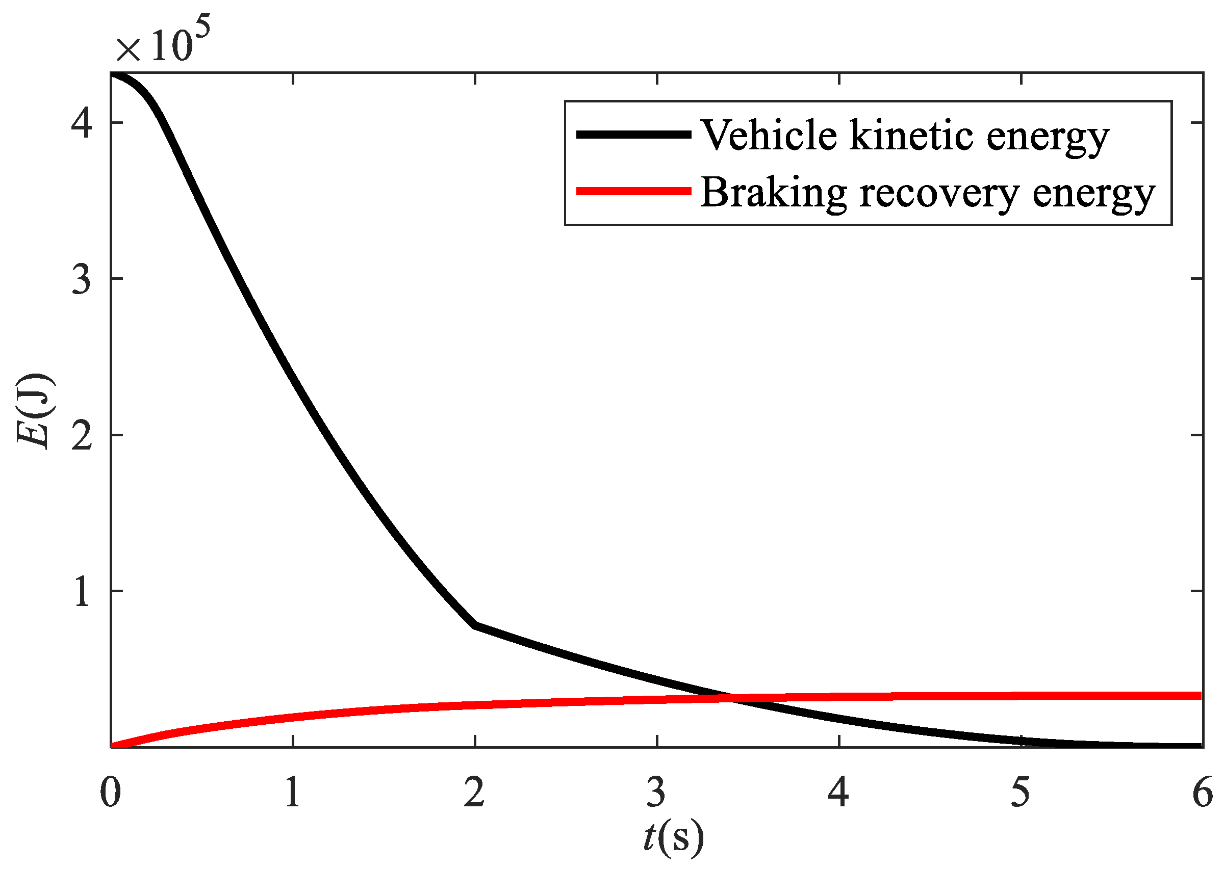
Figure 12 shows the velocity change of vehicle and wheels. The vehicle velocity is close to the wheel velocity, and the dangerous situation of locked does not occur during the braking process, which means better effect of slip control, and the wheel’s velocity variation of controller 1 have low-frequency jitter than that of controller 2 during the whole ABS control, which demonstrates the smaller fluctuations of regenerative braking torque of controller 1. Figure 13 exhibits the curves of the vehicle’s kinetic energy and reclaimed regenerative braking energy, and the energy recovery efficiency could reach 7.6%, which illustrates better energy recovery efficiency of the electric vehicle under a joint-μ road.
4.2. Braking Performance Comparison under the Spilt-μ Road Surface
Figure 14 exhibits the peak adhesion coefficient μ of joint-μ road, the right side of the road with high value of friction coefficient while the left side with a low value of friction coefficient. This working condition aggravates the uncertain environment of the braking process.
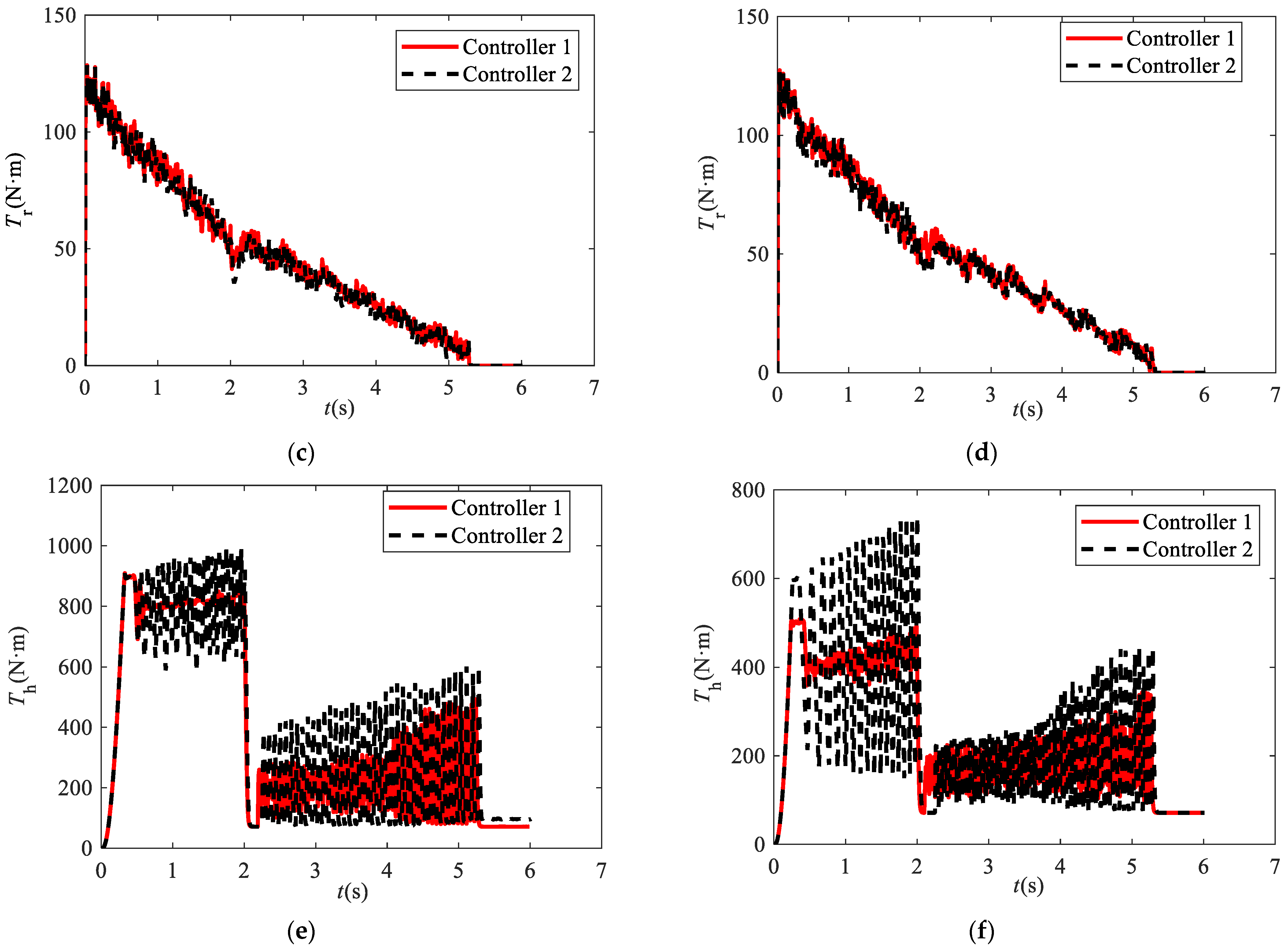
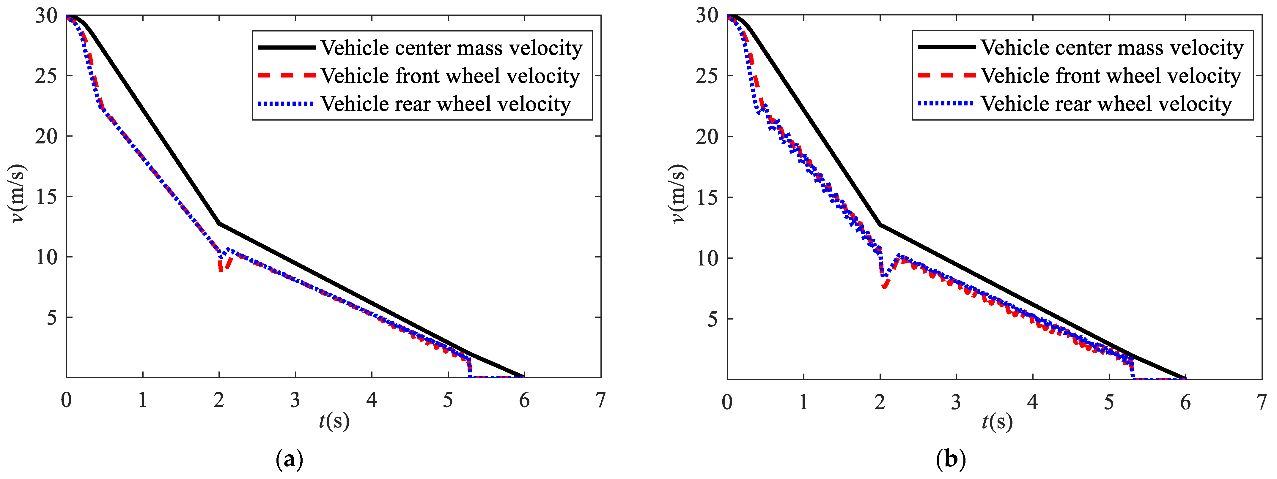
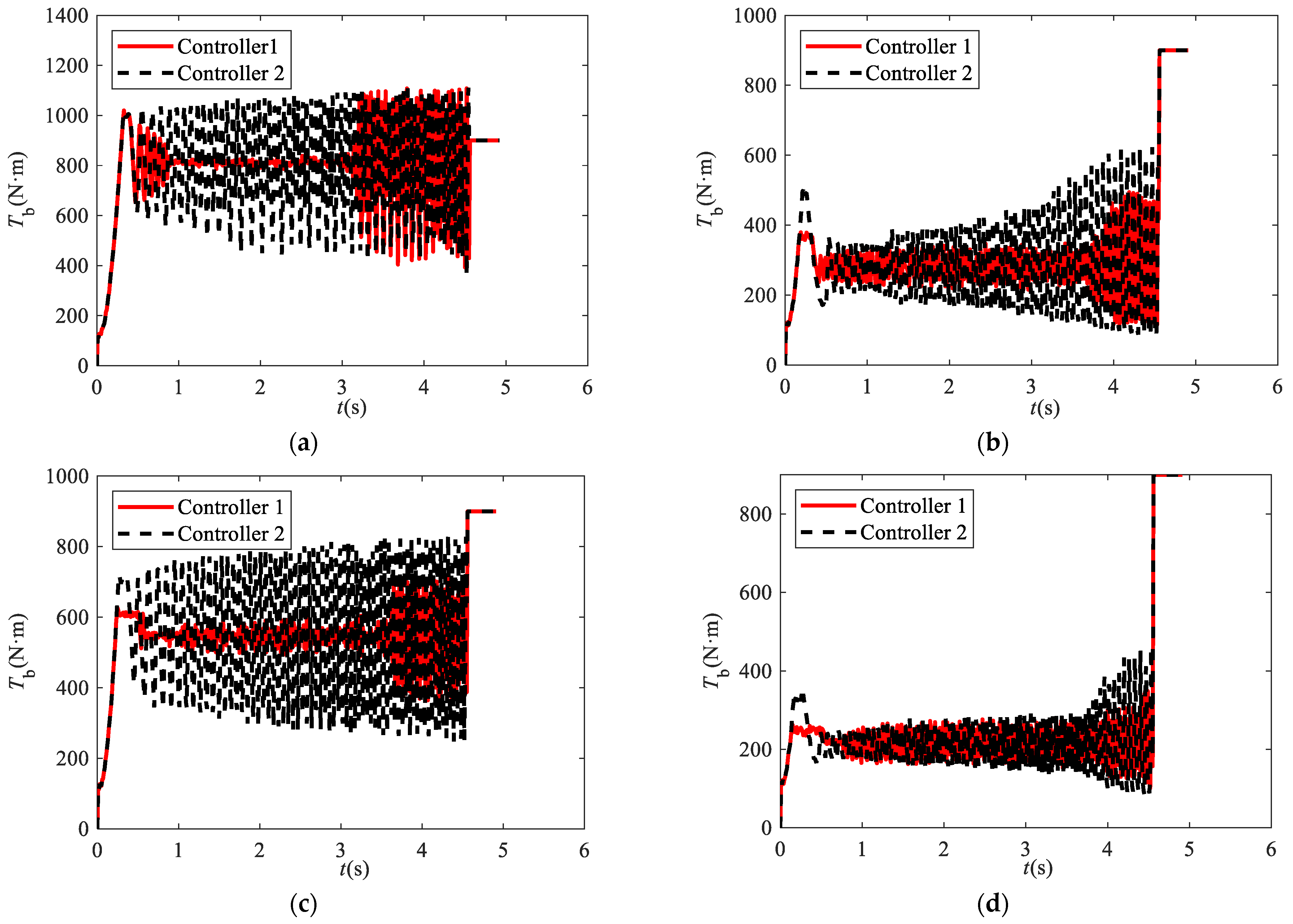
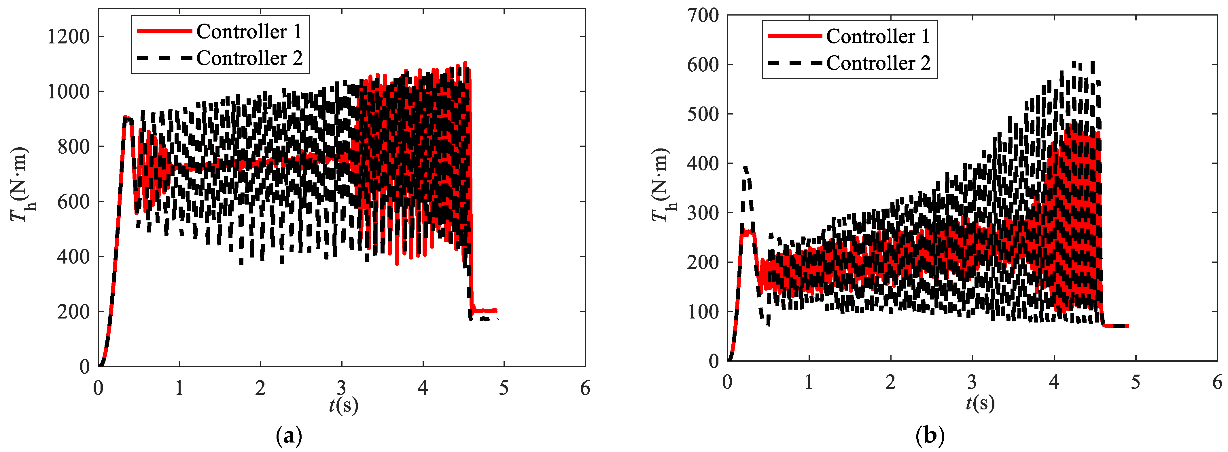
Figure 15, Figure 16, Figure 17, Figure 18 and Figure 19 exhibit the comparison curves of slip rate, total braking torque, regenerative braking torque, hydraulic braking torque, and velocity between controllers 1 and 2 under condition 2.
As shown in Figure 15, all the controllers could remain optimal slip rate tracking; however, the RMS of slip rate error for each wheel of controller 1 is reduced by 33.92%, 67.61%, 28.27%, and 46.30%, respectively. The slip control curves of interval type-2 fuzzy logic have smaller fluctuations than that of type-1 fuzzy logic before 4 s, which illustrates the control effect of interval type-2 fuzzy logic with the different road surfaces for wheels better than type-1 fuzzy logic and preferable adaption of diverse working conditions.
Figure 16, Figure 17 and Figure 18 illustrate the braking torque variation of controller 1 are more stable than that of controller 2 when the right wheels are braking on high friction coefficient and the left are braking on low friction coefficient. Due to the too small wheels velocity, the fluctuations of hydraulic braking torque become larger; however, the vehicle velocity has already reached to a low value, which means the fluctuations have less impact on the braking safety.
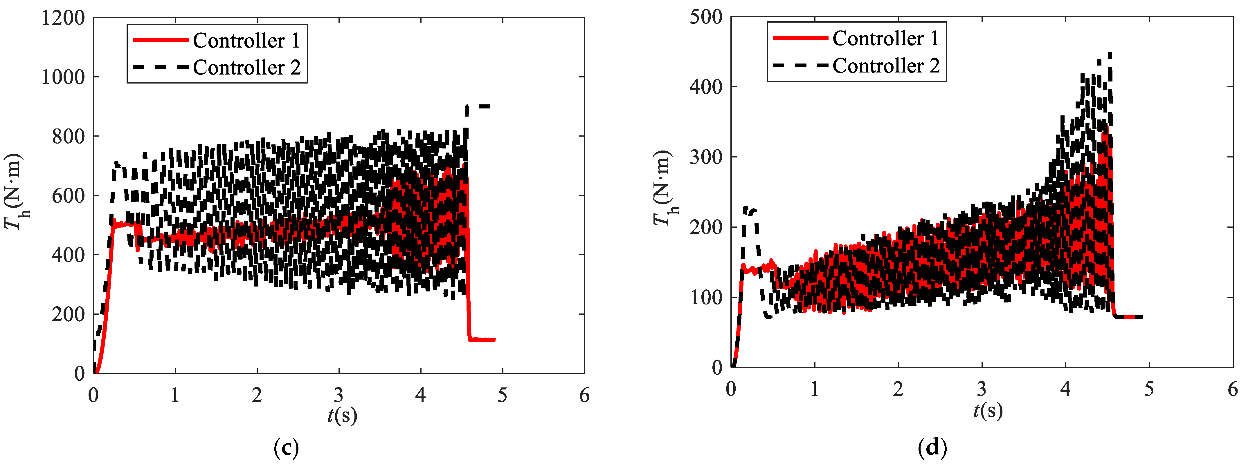
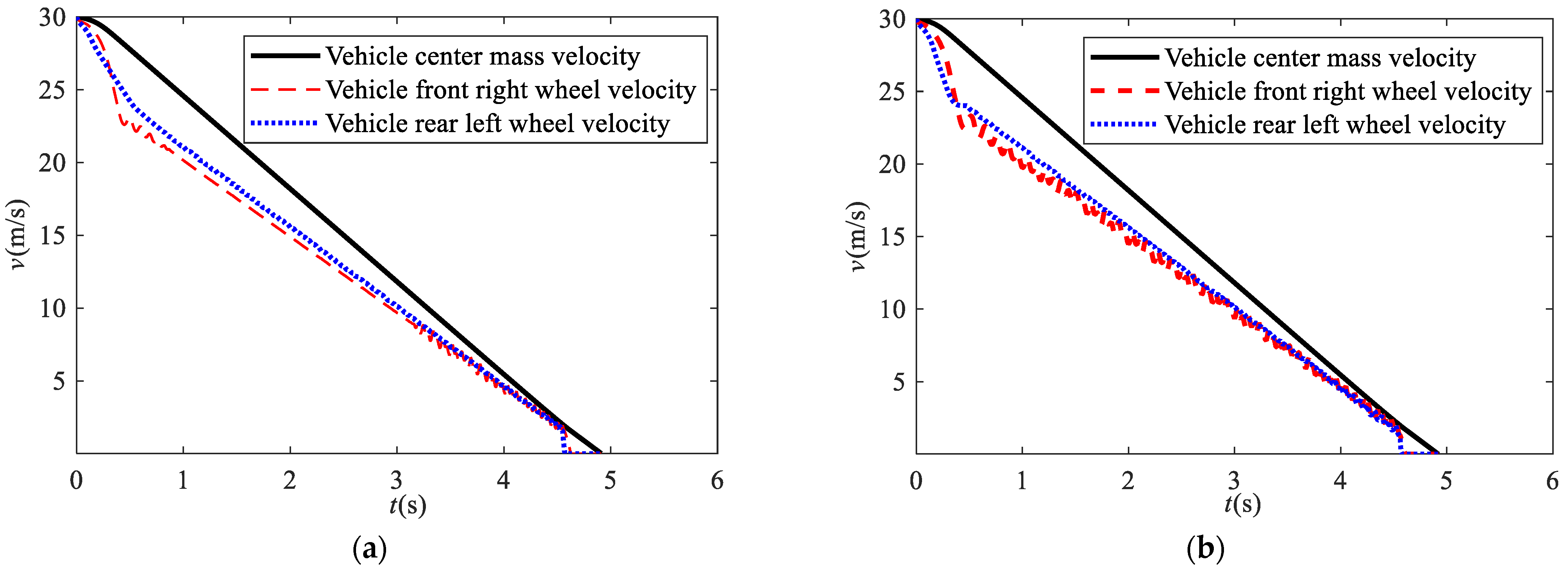
Figure 19 exhibits the velocity of the vehicle and wheels. The velocity variation of the rear left wheel for the two controllers are similar under a low value of friction coefficient refer to wet road. However, the vehicle front right wheel velocity of controller 1 has less jitters than that of controller 2 under a high value of friction coefficient, which means better braking safety and braking comfort ability when the wheels braking on different surfaces simultaneously. The results illustrate the interval type-2 fuzzy logic anti-lock braking control has better anti-interference ability and better adaption of different working conditions than the traditional type-1 fuzzy logic control.
5. Conclusions
In this present study, an efficient interval type-2 fuzzy logic control method is developed and successfully applied in an electro-hydraulic compound anti-lock braking controller. The interval type-2 fuzzy logic enhances the ability of anti-interference for fuzzy control during the braking process by the membership function expansion method. It means every single fuzzy variable is described by both lower and upper membership functions. Furthermore, to fully exert the advantages of regenerative braking and recapture more lost kinetic energy, the corresponding braking torque allocation strategy is designed to maintain the maximum energy recovery efficiency on the premise of safe braking. Additionally, to verify the braking performances of the proposed controller, simulations of two working conditions specified to complex and changing road surface are conducted to illustrate the effectiveness of the proposed controller compared with type-1 fuzzy logic control. The simulation results show that the wheel slip rate tracking RMS of interval type-2 fuzzy logic controller for front and rear wheels decreased by 54.44% and 57.28%, respectively, compared with type-1 fuzzy logic control under the joint-μ road, and for each wheel, the RMS reduced by 33.92%, 67.61%, 28.27%, and 46.30%, compared with type-1 fuzzy logic control under the spilt-μ road. Moreover, ideal regenerative braking energy recovery efficiencies of 7.6% and 9.38% can be achieved by the proposed electro-hydraulic compound anti-lock braking system under joint-μ and split-μ road surfaces, respectively. In addition, the braking torque variation curve of type-2 fuzzy control is more stable and with minor fluctuation than type-1 fuzzy control, which indicates the better robustness of braking torque control in the process of anti-lock braking and bring preferable braking feeling to the driver. Therefore, the interval type-2 fuzzy logic control ensures the function of energy recovery and anti-lock braking with fully improving the anti-interference, stability, and robustness of slip rate control in the uncertain process of electro-hydraulic compound anti-lock braking.
In further research, our future concentrated work is about improving the interval type-2 fuzzy controller from two main aspects. Innovative braking torque allocation strategy is a key issue to solve, which is useful for interval type-2 fuzzy logic controllers to obtain a better braking energy recovery. Furthermore, a less time-consuming type reduction method would be studied to optimize the interval type-2 fuzzy logic algorithm.
Author Contributions
Conceptualization, L.L. and J.W.; methodology, L.L.; software, L.L.; validation, L.L. and J.W.; formal analysis, L.L.; investigation, J.W.; resources, J.L.; data curation, L.L. and J.L.; writing—original draft preparation, L.L.; writing—review and editing, J.W. and J.L.; visualization, J.L.; supervision, J.W. All authors have read and agreed to the published version of the manuscript.
Funding
This work was supported by the Zhejiang Provincial Department of Education Scientific Research Project (Grant No. 20020060-F); Open Research Fund of Anhui Engineering Technology Research Center of Automotive New Technique (Grant No. QCKJ202102); Wenzhou Major Science and Technology Innovation Project of China (ZG2021028); and Scientific Research Start-up Project at Zhejiang Sci-Tech University (Grant No. 20022303-Y).
Institutional Review Board Statement
Not applicable.
Informed Consent Statement
Not applicable.
Data Availability Statement
Data are available upon request by contacting the first author.
Acknowledgments
Thank you to all reviewers for their suggestions to make this paper better.
Conflicts of Interest
The authors declare no conflict of interest.
Nomenclature
| A | windward area of vehicle | Rω | rolling radius of wheel |
| type-2 fuzzy set of e | RΩ | internal resistance of motor | |
| Af | area of brake wheel cylinder piston | SH | horizontal bias of Magic Formula tire model |
| B | stiffness coefficient of Magic Formula tire model | SV | vertical bias of Magic Formula tire model |
| type-2 fuzzy set of | Tb | braking torque | |
| C | shape coefficient of Magic Formula tire model | Tb_i | ideal anti-lock braking torque |
| type-2 fuzzy set of Tb_i | Tb_il | left endpoint of the interval type-2 fuzzy set output | |
| Ce | equivalent liquid capacity characteristic coefficient of the pipeline and wheel cylinder | Tb_ir | right endpoint of the interval type-2 fuzzy set output |
| c | the center position of the membership function | Tb_r | real anti-lock braking torque |
| D | peak value of Magic Formula tire model | Td | driving torque |
| d | d-axis of permanent magnet synchronous motor | Tf | rolling resistance torque |
| E | curvature coefficient of Magic Formula tire model | Th | hydraulic braking torque |
| e | difference value of wheel slip rate and the ideal slip rate | Th_i | ideal hydraulic braking torque |
| change rate of e | Th_r | real hydraulic braking torque | |
| slip rate error | Tr | regenerative braking torque | |
| Fx | longitudinal force | Tr_i | ideal regenerative braking torque |
| Fy | lateral force | Tr_r | real regenerative braking torque |
| FD | air resistance force | Tri_max | maximum energy recovery regenerative braking torque |
| Ff | rolling resistance force | tf | front wheelbase |
| Fmn | activation degree interval of mn rule | tr | rear wheelbase |
| f | upper bound of the interval type-2 fuzzy output interval | u | second variables of type-2 fuzzy set |
| g | lower bound of the interval type-2 fuzzy output interval | ud | voltage motor d-axis |
| Iz | vehicle’s moment of inertia around the z-axis | uq | voltage motor q-axis |
| ia | actual current of phase a | vx | velocity of electric vehicle along the x-axis |
| ib | actual current of phase b | vy | velocity of electric vehicle along the y-axis |
| ic | actual current of phase c | acceleration of electric vehicle along the x-axis | |
| iai | expected current of phase a | acceleration of electric vehicle along the y-axis | |
| ibi | expected current of phase b | X | fuzzy domain |
| ici | expected current of phase c | x | first variable of type-2 fuzzy set |
| id | current of motor d-axis | Y | output variable of Magic Formula tire model |
| iq | current of motor q-axis | β | angle between the air resistance and the driving direction |
| idi | expected current of motor d-axis | γ | vehicle yaw angle |
| iqi | expected current of motor q-axis | yaw angular velocity | |
| Jx | primary membership degree | steering angle of the wheel | |
| Jw | wheel’s moment of inertia | η | wheel cylinder efficiency |
| L | left transition point | θ | rotation angle of rotor |
| Ld | inductor of motor d-axis | λ | slip rate |
| Lq | inductor of motor q-axis | λd | ideal slip rate |
| la | distances between the mass center of the vehicle and the front axle | μ | road peak adhesion coefficient |
| lb | distances between the mass center of the vehicle and the rear axle | μb | friction coefficient of brake |
| m | the mass of the electric vehicle | secondary membership degree | |
| Pm | pressure of the main cylinder | ψf | motor magnetic chain |
| Pr | pressure of low-pressure accumulator | τ | time delay of brake |
| Pw | pressure of the wheel cylinder | transmission lag time of solenoid valve and pipeline during pressurization | |
| p | number of pole-pairs | transmission lag time of solenoid valve and pipeline during decompression | |
| q | q-axis of permanent magnet synchronous motor | ω | angular velocity of wheel |
| R | the right transition point | angular acceleration of the wheel | |
| Rb | brake effective radius of friction | ωd | rotor angular velocity of motor |
| Re | equivalent liquid resistance characteristic coefficient of the pipeline and wheel cylinder when the pressure is increased | lower edge of the activate interval for number mn rule | |
| equivalent liquid resistance characteristic coefficient of the pipeline and wheel cylinder when the pressure is reduced | upper edge of the activate interval for number mn rule |
References
- Hu, D.H.; Wang, Y.T.; Li, J.W.; Yang, Q.Q.; Wang, J. Investigation of optimal operating temperature for the PEMFC and its tracking control for energy saving in vehicle applications. Energy Convers. Manag. 2021, 249, 114842. [Google Scholar] [CrossRef]
- Liu, B.H.; Li, L.; Wang, X.Y.; Cheng, S. Hybrid electric vehicle downshifting strategy based on stochastic dynamic programming during regenerative braking process. IEEE Trans. Veh. Technol. 2018, 67, 4716–4727. [Google Scholar] [CrossRef]
- Ko, S.; Song, C.; Kim, H. Cooperative control of the motor and the electric booster braking to improve the stability of an in-wheel electric vehicle. Int. J. Automot. Technol. 2016, 17, 447–456. [Google Scholar] [CrossRef]
- Pretagostini, F.; Ferranti, L.; Berardo, G.; Ivanov, V.; Shyrokau, B. Survey on wheel slip control design strategies, evaluation and application to antilock braking systems. IEEE Access 2020, 8, 10951–10970. [Google Scholar] [CrossRef]
- Yuan, Y.; Zhang, J.Z.; Li, Y.T.; Li, C. A novel regenerative electrohydraulic brake system: Development and hardware-in-loop tests. IEEE Trans. Veh. Technol. 2018, 67, 11440–11452. [Google Scholar] [CrossRef]
- Rajendran, S.; Spurgeon, S.K.; Tsampardoukas, G.; Hampson, R. Estimation of road frictional force and wheel slip for effective anti-lock braking system (ABS) control. Int. J. Robust Nonlinear Control 2019, 29, 736–765. [Google Scholar] [CrossRef] [Green Version]
- Chiang, W.P.; Yin, D.J.; Shimizu, H. Slip-based regenerative ABS control for in-wheel-motor drive EV. J. Chin. Inst. Eng. 2015, 38, 220–231. [Google Scholar] [CrossRef]
- Yang, Y.; Tang, Q.S.; Bolin, L.; Fu, C.Y. Dynamic coordinated control for regenerative braking system and anti-lock braking system for electrified vehicles under emergency braking conditions. IEEE Access 2020, 8, 172664–172667. [Google Scholar] [CrossRef]
- Feng, X.L.; Hu, J. Discrete fuzzy adaptive PID control algorithm for automotive anti-lock braking system. J. Ambient. Intell. Humaniz. Comput. 2021, 1–10. [Google Scholar] [CrossRef]
- Sun, J.H.; Xue, X.D.; Cheng, K.W.E. Fuzzy sliding mode wheel slip ratio control for smart vehicle anti-lock braking system. Energies 2019, 12, 2501. [Google Scholar] [CrossRef] [Green Version]
- Verma, R.; Ginoya, D.; Shendge, P.D.; Phadke, S.B. Slip regulation for anti-lock braking system using multiple surface sliding controller combined with inertial delay control. Veh. Syst. Dyn. 2015, 53, 1150–1171. [Google Scholar] [CrossRef]
- Nguyen, A.-T.; Taniguchi, T.; Eciolaza, L.; Campos, V.; Palhares, R.; Sugeno, M. Fuzzy control systems: Past, present and future. IEEE Comput. Intell. Mag. 2019, 14, 56–58. [Google Scholar] [CrossRef]
- Wang, T.C.; Sui, S.; Tong, S.C. Data-based adaptive neural network optimal output feedback control for nonlinear systems with actuator saturation. Neurocomputing 2017, 247, 192–201. [Google Scholar] [CrossRef]
- Banaei, A.; Alamatian, J. New genetic algorithm for structural active control by considering the effect of time delay. J. Vib. Control 2021, 27, 743–758. [Google Scholar] [CrossRef]
- Fargione, G.; Tringali, D.; Risitano, G. A fuzzy-genetic control system in the ABS for the control of semi-active vehicle suspensions. Mechatronics 2016, 3, 89–102. [Google Scholar] [CrossRef]
- Aksjonov, A.; Vodovozov, V.; Augsburg, K.; Petlenkov, E. Design of regenerative anti-lock braking system controller for 4 in-wheel-motor drive electric vehicle with road surface estimation. Int. J. Automot. Technol. 2018, 19, 727–742. [Google Scholar] [CrossRef] [Green Version]
- Mokarram, M.; Khoei, A.; Hadidi, K. A fuzzy Anti-lock braking system (ABS) controller using CMOS circuits. Microprocess. Microsyst. 2019, 70, 47–52. [Google Scholar] [CrossRef]
- Castillo, O.; Amador-Angulo, L.; Castro, J.R.; Garcia-Valdez, M. A comparative study of type-1 fuzzy logic systems, interval type-2 fuzzy logic systems and generalized type-2 fuzzy logic systems in control problems. Inf. Sci. 2016, 354, 257–274. [Google Scholar] [CrossRef]
- Hailemichael, A.; Salaken, S.M.; Karimoddini, A.; Homaifar, A.; Abbas, K.; Nahavandi, S. Developing a computationally effective interval type-2 TSK fuzzy logic controller. J. Intell. Fuzzy Syst. 2020, 38, 1915–1928. [Google Scholar] [CrossRef]
- Gonzalez, C.I.; Melin, P.; Castro, J.R.; Mendoza, O.; Castillo, O. An improved sobel edge detection method based on generalized type-2 fuzzy logic. Soft Comput. 2016, 20, 773–784. [Google Scholar] [CrossRef]
- Zhang, Z.M. Trapezoidal interval type-2 fuzzy aggregation operators and their application to multiple attribute group decision making. Neural Comput. Appl. 2018, 29, 1039–1054. [Google Scholar] [CrossRef]
- Gaxiola, F.; Melin, P.; Valdez, F.; Castro, J.R.; Castillo, O. Optimization of type-2 fuzzy weights in backpropagation learning for neural networks using Gas and PSO. Appl. Soft Comput. 2016, 38, 860–871. [Google Scholar] [CrossRef]
- Sanchez, M.A.; Castillo, O.; Castro, J.R. Generalized type-2 fuzzy systems for controlling a mobile robot and a performance comparison with interval type-2 and type-1 fuzzy systems. Expert Syst. Appl. 2015, 42, 5904–5914. [Google Scholar] [CrossRef]
- Bin Peeie, M.H.; Ogino, H.; Oshinoya, Y. Skid control of a small electric vehicle with two in-wheel motors: Simulation model of ABS and regenerative brake control. Int. J. Crashworthiness 2016, 21, 396–406. [Google Scholar] [CrossRef] [Green Version]
- Yu, D.L.; Wang, W.S.; Zhang, H.B. Research on Anti-Lock Braking Control Strategy of Distributed-Driven Electric Vehicle. IEEE Access 2020, 8, 162467–162478. [Google Scholar] [CrossRef]
- Vignati, M.; Sabbioni, E. Force-based braking control algorithm for vehicles with electric motors. Veh. Syst. Dyn. 2020, 58, 1348–1366. [Google Scholar] [CrossRef]
- Wang, J.C.; He, R.; Kim, Y.-B. Optimal Anti-Lock Braking Control with Nonlinear Variable Voltage Charging Scheme for an Electric Vehicle. IEEE Trans. Veh. Technol. 2020, 69, 7211–7222. [Google Scholar] [CrossRef]
- Zhao, X.M.; Mo, H.; Yan, K.F.; Li, L.X. Type-2 fuzzy control for driving state and behavioral decisions of unmanned vehicle. IEEE-CAA J. Autom. Sin. 2020, 7, 178–186. [Google Scholar] [CrossRef]
- Karnik, N.N.; Mendel, J.M.; Liang, Q.L. Type-2 fuzzy logic system. IEEE Trans. Fuzzy Syst. 1999, 7, 643–658. [Google Scholar] [CrossRef] [Green Version]
- Wang, J.C.; Lv, L.F.; Ren, J.Y.; Chen, S.A. Time delay compensation using a Taylor series compound robust scheme for a semi-active suspension with magneto rheological damper. Asian J. Control. 2021. [CrossRef]
- Wang, J.C.; He, R.; Kim, Y.-B. Optimal control of regenerative hydraulic composite braking system based on a voltage variable charging control scheme. Proc. Inst. Mech. Eng. Part D-J. Automob. Eng. 2020, 234, 536–551. [Google Scholar] [CrossRef]
- Aksjonov, A.; Augsburg, K.; Vodovozov, V. Design and simulation of the robust ABS and ESP fuzzy logic controller on the complex braking maneuvers. Appl. Sci. 2016, 6, 382. [Google Scholar] [CrossRef]
Figure 1.
Vehicle dynamic model: (a) dynamic model of electric vehicle and (b) dynamic model of tire.
Figure 1.
Vehicle dynamic model: (a) dynamic model of electric vehicle and (b) dynamic model of tire.

Figure 2.
Scheme of PMSM’s torque tracking control.

Figure 3.
The elements of a type-2 fuzzy set.

Figure 4.
Schematic diagram of interval type-2 fuzzy logic electro-hydraulic compound anti-lock braking control system.
Figure 4.
Schematic diagram of interval type-2 fuzzy logic electro-hydraulic compound anti-lock braking control system.

Figure 5.
Membership function of e.

Figure 6.
Membership function of .

Figure 7.
Membership function of Tb_i.

Figure 8.
Flowchart of the braking torque distribution strategy.

Figure 9.
The change of road peak adhesion coefficient under condition 1.

Figure 10.
The slip rate under condition 1: (a) the slip rate of front wheels; (b) the slip rate of rear wheels.
Figure 10.
The slip rate under condition 1: (a) the slip rate of front wheels; (b) the slip rate of rear wheels.

Figure 11.
The braking torques under condition 1: (a) the total braking torque of front wheels; (b) the total braking torque of rear wheels; (c) the regenerative braking torque of front wheels; (d) the regenerative braking torque of rear wheels; (e) the hydraulic braking torque of front wheels; (f) the hydraulic braking torque of rear wheels.


Figure 12.
The vehicle and wheels velocity for two controllers under condition 1: (a) the vehicle and wheels velocity for controller 1; (b) the vehicle and wheels velocity for controller 2.
Figure 12.
The vehicle and wheels velocity for two controllers under condition 1: (a) the vehicle and wheels velocity for controller 1; (b) the vehicle and wheels velocity for controller 2.

Figure 13.
The energy change of vehicle with controller 1 under condition 1.

Figure 14.
The road peak adhesion coefficient of condition 2.

Figure 15.
The slip rate under condition 2: (a) the slip rate of front right wheel; (b) the slip rate of front left wheel; (c) the slip rate of rear right wheel; (d) the slip rate of rear left wheel.
Figure 15.
The slip rate under condition 2: (a) the slip rate of front right wheel; (b) the slip rate of front left wheel; (c) the slip rate of rear right wheel; (d) the slip rate of rear left wheel.

Figure 16.
The total braking torques under condition 2: (a) the total braking torque of front right wheel; (b) the total braking torque of front left wheel; (c) the total braking torque of rear right wheel; (d) the total braking torque of rear left wheel.
Figure 16.
The total braking torques under condition 2: (a) the total braking torque of front right wheel; (b) the total braking torque of front left wheel; (c) the total braking torque of rear right wheel; (d) the total braking torque of rear left wheel.

Figure 17.
The regenerative braking torques under condition 2: (a) the regenerative braking torque of front right wheel; (b) the regenerative braking torque of front left wheel; (c) the regenerative braking torque of rear right wheel; (d) the regenerative braking torque of rear left wheel.
Figure 17.
The regenerative braking torques under condition 2: (a) the regenerative braking torque of front right wheel; (b) the regenerative braking torque of front left wheel; (c) the regenerative braking torque of rear right wheel; (d) the regenerative braking torque of rear left wheel.

Figure 18.
The hydraulic braking torques under condition 2: (a) the hydraulic braking torque of front right wheel; (b) the hydraulic braking torque of front left wheel; (c) the hydraulic braking torque of rear right wheel; (d) the hydraulic braking torque of rear left wheel.
Figure 18.
The hydraulic braking torques under condition 2: (a) the hydraulic braking torque of front right wheel; (b) the hydraulic braking torque of front left wheel; (c) the hydraulic braking torque of rear right wheel; (d) the hydraulic braking torque of rear left wheel.


Figure 19.
The vehicle and wheel velocities for two controllers under condition 2: (a) the vehicle and wheel velocities for controller 1; (b) the vehicle and wheel velocities for controller 2.
Figure 19.
The vehicle and wheel velocities for two controllers under condition 2: (a) the vehicle and wheel velocities for controller 1; (b) the vehicle and wheel velocities for controller 2.

Figure 20.
The energy change of vehicle with controller 1 under condition 2.


Table 1.
Fuzzy control rules.
| Tb_i | ||||||
|---|---|---|---|---|---|---|
| NB | NS | ZE | PS | PM | ||
| e | NB | BR | BR | BR | BR | BR |
| NS | BI | BI | BI | BI | BI | |
| ZE | MI | MI | MI | MI | MI | |
| PS | SM | SM | SM | SM | SM | |
| PB | SR | SR | SR | SR | SR | |
Table 2.
Main parameters.
| Variables | Values | Variables | Values |
|---|---|---|---|
| m (kg) | 960 | δ | 0 |
| A (m2) | 2.57 | Pr (MPa) | 0.375 |
| Iz (m·kg2) | 1600 | Rω (m) | 0.29 |
| Pm (MPa) | 15 | Jω (m·kg2) | 2.1 |
Table 3.
Road surface parameters.
| Road Condition | Slip Rate (Optimal) | Coefficient (Maximum) | Coefficient (Slip Rate = 1) |
|---|---|---|---|
| Dry | 0.18 | 0.90 | 0.80 |
| Snow | 0.14 | 0.30 | 0.20 |
Publisher’s Note: MDPI stays neutral with regard to jurisdictional claims in published maps and institutional affiliations. |
© 2021 by the authors. Licensee MDPI, Basel, Switzerland. This article is an open access article distributed under the terms and conditions of the Creative Commons Attribution (CC BY) license (https://creativecommons.org/licenses/by/4.0/).
Share and Cite
MDPI and ACS Style
Lv, L.; Wang, J.; Long, J. Interval Type-2 Fuzzy Logic Anti-Lock Braking Control for Electric Vehicles under Complex Road Conditions. Sustainability 2021, 13, 11531. https://0-doi-org.brum.beds.ac.uk/10.3390/su132011531
AMA Style
Lv L, Wang J, Long J. Interval Type-2 Fuzzy Logic Anti-Lock Braking Control for Electric Vehicles under Complex Road Conditions. Sustainability. 2021; 13(20):11531. https://0-doi-org.brum.beds.ac.uk/10.3390/su132011531
Chicago/Turabian StyleLv, Linfeng, Juncheng Wang, and Jiangqi Long. 2021. "Interval Type-2 Fuzzy Logic Anti-Lock Braking Control for Electric Vehicles under Complex Road Conditions" Sustainability 13, no. 20: 11531. https://0-doi-org.brum.beds.ac.uk/10.3390/su132011531
Note that from the first issue of 2016, this journal uses article numbers instead of page numbers. See further details here.