Article

Synthesis and Electrochemical Properties of Lignin-Derived High Surface Area Carbons

1
Department of Chemistry, Illinois Institute of Technology, Chicago, IL 60616, USA
2
Department of Physics & CSRRI, Illinois Institute of Technology, Chicago, IL 60616, USA
*
Author to whom correspondence should be addressed.
Submission received: 28 February 2022 / Revised: 22 March 2022 / Accepted: 30 March 2022 / Published: 6 April 2022
(This article belongs to the Collection Featured Articles for Surfaces)

Abstract

:
Activated carbons play an essential role in developing new electrodes for renewable energy devices due to their electrochemical and physical properties. They have been the subject of much research due to their prominent surface areas, porosity, light weight, and excellent conductivity. The performance of electric double-layer capacitors (EDLCs) is highly related to the morphology of porous carbon electrodes, where high surface area and pore size distribution are proportional to capacitance to a significant extent. In this work, we designed and synthesized several activated carbons based on lignin for both supercapacitors and Li-S batteries. Our most favorable synthesized carbon material had a very high specific surface area (1832 m2·g−1) and excellent pore diameter (3.6 nm), delivering a specific capacitance of 131 F·g−1 in our EDLC for the initial cycle. This translates to an energy density of the supercapacitor cell at 55.6 Wh·kg−1. Using this material for Li-S cells, composited with a nickel-rich phosphide and sulfur, showed good retention of soluble lithium polysulfide intermediates by maintaining a specific capacity of 545 mA·h·g−1 for more than 180 cycles at 0.2 C.

1. Introduction

Lignin is the second most abundant renewable bio-resource in nature, after cellulose. It is an amorphous high molecular weight complex biopolymer with heterogeneous aromatic structure, derived mainly from p-coumaryl, coniferyl and sinapyl alcohols, with a total worldwide production of approximately 26 million tons per year. Unlike cellulose, which consists of single intermonomeric linkages, lignin has no structural regularity within its polymeric framework. In lignin macromolecules, the monomeric units p-hydroxyphenyl (H), guaiacyl (G) and syringyl (S) are linked by a variety of carbon–oxygen and carbon–carbon bonds (Figure 1). Lignin is manufactured from low-cost natural precursors, such as woody plants and paper mill wastes. The use of lignin as a precursor to carbonaceous materials has gained interest due to its high percentage of aromatic residues, low cost, and high availability [1,2,3,4].
Due to lignin’s high carbon content and functionalized phenolic structure, it can be considered one of the ideal precursors for activated carbons, albeit the activation of lignin produces mostly micropores. The control of pore sizes during carbon synthesis is challenging, primarily due to mass shrinking upon pyrolysis and the resulting collapse of pore walls [5]. However, notable efforts have been made to produce porous carbons from lignin because of their high aromatic contents. Recently, lignin-containing nanocomposites have been developed with enhanced functionality for energy storage, such as lignin-polypyrrole and lignin-graphene hybrid electrodes [6].
Electric double-layer capacitors (EDLCs), the most studied class of supercapacitors, have matured technologically and served a good segment of the electrical energy storage market where Li-ion batteries (LIBs) are not applicable. EDLCs are vital for memory backup systems, instantaneous electricity compensators, auxiliary power units, electric vehicle starters, and many other energy storage devices owing to their ability to provide high specific power (or power density) (Ps > 10 kW·kg−1), high-speed charge/discharge capability (within seconds), a high safety rating, a broad range of operating temperatures (−40 to 80 °C), and outstanding cycling stability (>100,000 cycles) compared to batteries [7,8,9,10,11,12]. However, one significant drawback of EDLCs limiting their broad-range application is specific energy (Es) or energy density, which harbors ~10–25 Wh·kg−1. That means this value is at least an order of magnitude lower than LIBs (Es ~200–250 Wh·kg−1) [13]. Supercapacitors capable of delivering high Es without sacrificing power density and cycle life are critically needed for numerous practical applications, viz., hybrid electric vehicles, mobile electronics, fuel cells, industrial forks, wind turbine energy storage, regenerative braking and uninterrupted power supply devices [14,15,16,17,18,19,20].
EDLCs store and release electrical energy through ion adsorption and desorption on the electrode–electrolyte interface. While their specific capacitance (C) is proportional to the specific surface area of the electrodes, the specific energy has a square relationship with the maximum safe operating voltage (V) of the electrolyte system, where Es = 0.5 CV2. Thus, the preparation of high surface area electrodes and electrochemically stable electrolytes is critical to fabricating superior EDLCs. In the past decade, extensive research studies have been conducted worldwide to achieve levels of specific energy for EDLCs similar to those of batteries. Towards this effort, only a few research groups have been able to pass the specific energy barrier of 100 Wh·kg−1, either by creating very high surface area electrode materials (for high C) or by designing new electrolytes with high electrochemical stability (for high V) [21,22,23].
Up to now, a variety of carbon-based electrode materials, viz., activated carbons, carbon aerogels, carbon nanotubes, carbon nanofibers, graphene sheets, carbide-derived carbons, and composite materials containing metal oxides have been investigated [24,25,26,27,28,29,30]. Among these, activated carbons (ACs) have been widely employed as the primary electrode material in EDLCs because of their highly porous structure, cost-effectiveness, and high cycling durability. Recently, environmental issues have been pushing the preparation of ACs towards exploiting renewable resources or bio-wastes, including wood sawdust, dead neem leaves, coconut shells, bamboo, seaweed and others [31,32,33,34,35,36].
The energy density of EDLCs is strongly correlated to the morphology of the porous carbon electrodes, where high surface area and pore size distribution are proportional to capacitance to a significant extent. However, according to Barbieri et al., carbon-specific surface areas with values above 1200 m2·g−1 show a plateau with respect to capacitance, where it stops increasing linearly due to a saturation of charge [37]. Nonetheless, carbon materials have been the subject of much research due to their high surface area, porosity, light weight, and excellent conductivity in EDLCs and batteries, such as Li-S batteries (LSB). The most used conductive material to decrease resistance is active carbon black with high surface area and abundant micropores [37]. In the case of LSBs, porous carbon materials with high surface area well dispersed with sulfur ensure sufficient S loading, electron transport between the electrical conductor and the active materials, and the utilization of active materials [37,38]. Besides high surface area, which enables high sulfur loading, wrapping the cathode structure with a polysulfide absorbing material is essential. This will significantly enhance the retention of polysulfide intermediates in the cathode structure, leading to superior capacity retention [39]. Since S is not conductive but rather an insulator, the use of active carbon is the solution to electrical resistance. In addition to carbon black, other carbon materials, as already mentioned, are being researched for Li-S technology as they offer specific architectures and functionalities based on their morphologies, many of which can apply to EDLCs as well [40].
In this project, we selected lignin as the carbon precursor to prepare high surface area porous carbon (Void@C) materials for use in both EDLC and LSB (S@C@Ni12P5) electrodes due to the presence of a large number of aromatic rings in its chemical structure, which should lead to more graphitic structure and high yield. For the sulfur cathode host, the higher the surface area, the higher the contact of carbon with the active material, which means more active material utilization, especially when sulfur is an insulator. Similarly, for EDLC, the higher the surface area, the higher the ion adsorption on the surface, meaning high specific capacitance. Another important aspect of this research work was the use of more environmentally benign activation agents (Na2S2O3 and KCl vs. harsh/corrosive reagents such as KOH and ZnCl2). The work-up was also very simple (only water wash to remove all water-soluble salts). We also compared our research work with an industry standard activated carbon, Ketjen black (KB), which possesses surface area ~1450 m2·g−1; pore volume ~2.5 cm3·g−1 and pore diameter ~6.27 nm [41].

2. Experimental Section

2.1. Materials

Lignin (TCI), sodium thiosulfate (Na2S2O3, 99.9%, Fisher), and potassium chloride (KCl, 99.7%, Fisher) were used for the synthesis of high surface area carbons. Ethanol (EtOH, 99.5%), ammonium molybdate ((NH4)6Mo7O24·4H2O, ~83%), and urea (99.6%) were purchased from Fisher Scientific Chemicals, Waltham, MA, USA. Nickel(II) acetate tetrahydrate (Ni(Ac)2·4H2O, 98%), carboxymethyl cellulose binder (CMC), 1,3-dioxolane (DOL, 99.5%), polyacrylic acid (PAA, Mw ~450,000), sublimed sulfur (~100 mesh, 99.5%), and carbon black (Super-P carbon) were purchased from Alfa Aesar, Haverhill, MA, USA. Melamine (99%), dimethoxyethane (DME, 99.5%), lithium bis(trifluoromethanesulfonic)imide (LiTFSI, ≥99.0%) and lithium methoxide (LiOMe, 1.0 solution in methanol) were purchased from Sigma-Aldrich, St. Louis, MO, USA. Ionic liquid [1-butyl-2,3-dimethylimidazolium bis(trifluoromethanesulfonic)imide, 98.0%] was purchased from Tokyo Chemical Industry (TCI, Portland, OR, USA). All reagents were used as received. High purity nitrogen gas (99.998%) and argon gas (99.998%) were supplied by Wisco, Chicago, IL, USA.

2.2. Preparation of Void@C

Table 1 summarizes standard formulations and critical components for the preparation of high surface area carbons (HSACs). Void@C was prepared by modifying the method reported by Xiao-Fei Yu et al. [42]. An amount of 5.00 g of lignin was dissolved in 30 mL of deionized water, and an appropriate amount of Na2S2O3 and KCl was dissolved separately in 30 mL of deionized water. After stirring for 0.5 h, the two solutions were mixed and stirred for another 0.5 h. The mixed solution was placed in −70 °C for a day and then lyophilized for 3 days, resulting in a completely dehydrated and brittle material. The mixture was carbonized in a horizontal tube furnace at 800 °C for 1 h with a heating rate of 5.0 °C·min−1 under continuous nitrogen flow. The carbonized material was washed with water for 2 h at room temperature and centrifuged. After further filtration with ethanol and acetone, the sample was dried overnight in a 90 °C oven.

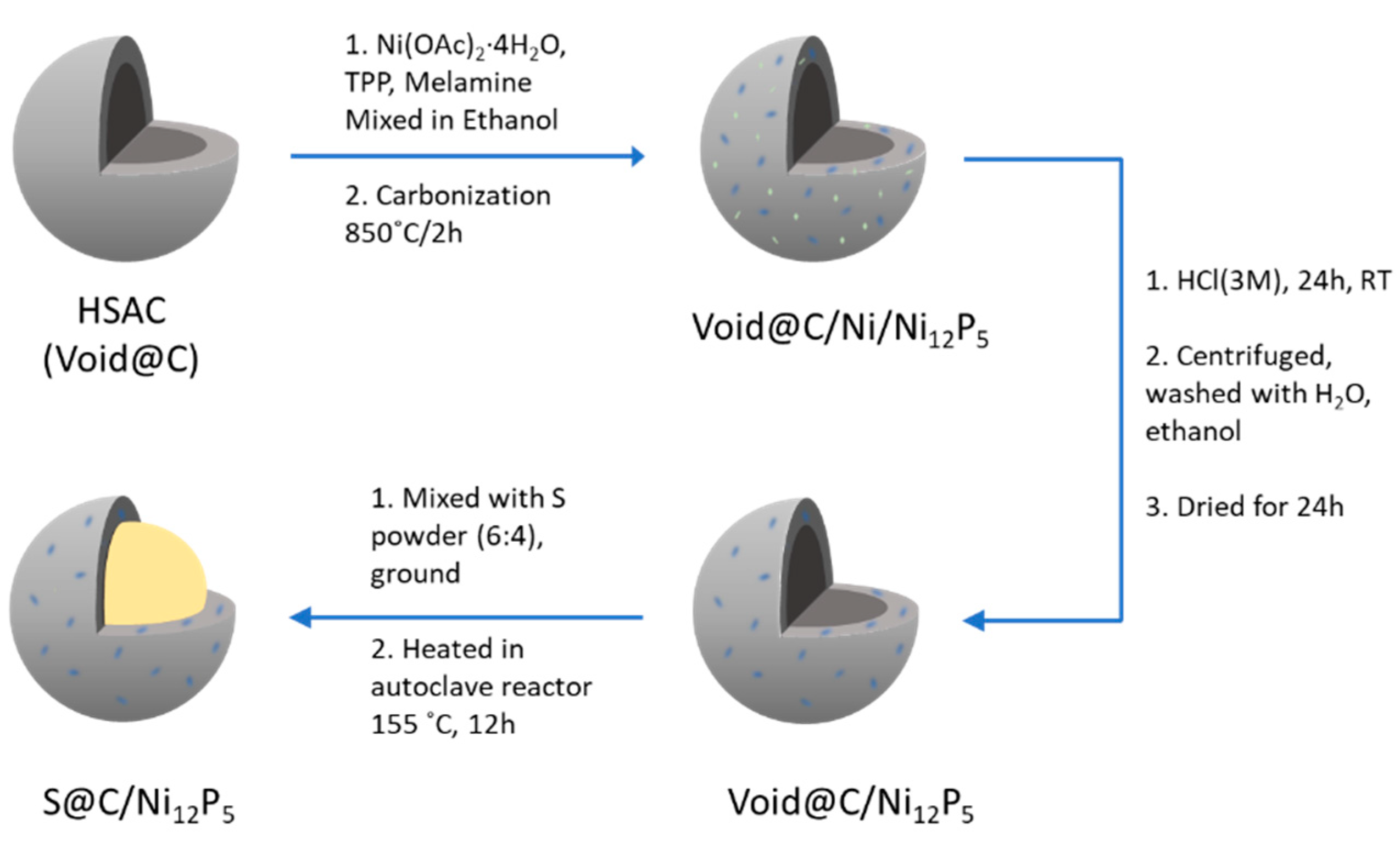
2.3. Preparation of C@Ni12P5

A 150 mg amount of an HSAC sample was ground and dispersed into 50 mL of ethanol solution, to which 500 mg of nickel(II) acetate tetrahydrate (Ni(OAc)2·4H2O) and 1.00 g of triphenyl phosphine were added under stirring. Then, melamine (250 mg) was added into the slurry. After 0.5 h of stirring, ethanol was removed in a rotary evaporator, leaving behind a greenish-brown powder. The mixture was then carbonized in a tube furnace at 850 °C in an argon atmosphere for 2 h at a heating rate of 5 °C·min−1 to obtain C@Ni/Ni12P5 composite. After the carbonization, the sample was treated with 3 M hydrochloric acid under stirring for 24 h at room temperature to remove reduced nickel particles. The solution was centrifuged and washed with water 5 times. After further filtration with ethanol and acetone, the sample was dried in a 90 °C oven overnight.

2.4. Preparation of S@C/Ni12P5

A 300 mg amount of C@Ni12P5 sample was ground with 470 mg of sulfur powder, forming a 4:6 mixture. The resulting fine powdery sample was placed in a Teflon-lined autoclave and heated at 155 °C for 12 h for sulfur infiltration to take place via the melt-diffusion process. A total of 720 mg of S@C/Ni12P5 was obtained after the sulfur infiltration.

2.5. Preparation of Polyacrylic Acid Lithium Salt (LiPAA)

LiPAA was prepared by partial neutralization of PAA using LiOMe. A 1 g amount of PAA was dissolved in 40 mL of 1:1 aqueous methanol. Then, 10 mL of LiOMe (0.5 eq. with respect to the PAA repeating unit) solution was added slowly under vigorous stirring for 1 h at room temperature. The solution was completely evaporated in a 50 °C oven and then a 70 °C oven to obtain dry LiPAA binder material.

2.6. Material Characterization

X-ray diffraction analysis (XRD) of Void@C/Ni12P5 and S@C/Ni12P5 samples was performed using a Bruker D2 Phaser X-ray diffractometer (Billerica, MA, USA) with an X-ray wavelength of 1.5406 Å. Scanning electron microscopy (SEM) and energy dispersive spectroscopy (EDS) (Phenom ProX, Phoenix, AZ, USA) were used to capture images and evaluate the nano-structure of the electrode materials. Nitrogen adsorption isotherms were measured at 77.4 K with a NOVA220e analyzer (Quantachrome 2014). The Brunauer-Emmett-Teller (BET) and Barrett-Joyner-Halenda (BJH) methods were used to calculate the surface area and pore size distribution of the HSACs. Thermogravimetric analysis (TGA) of sulfur cathode materials was accomplished under the nitrogen environment in the range of 25–600 °C at a heating rate of 10 °C·min−1 using a Thermogravimetric Analyzer (Mettler Toledo TGA2, Columbus, OH, USA).

2.7. Electrochemical Measurements

A slurry was prepared prior to the casting of supercapacitor electrodes. A 10 mg amount of carboxymethyl cellulose binder (CMC) was dissolved in 700 mg of H2O:EtOH (1:1) solution and dispersed in a Beadbug microtube homogenizer. Then, 80 mg of the selected HSAC sample (active material) and 10 mg of conductive carbon black (Super P) were added to the solution. After further mixing in the homogenizer for 0.5 h, the slurry microtube was vortexed for 12 h to obtain a smooth ink-like slurry. For the LSB cathode, S@C/Ni12P5 was used as the active material. LiPAA was added to 750 mg of water. After mixing in the homogenizer for 10 min, 80 mg of S@C/Ni12P5 and 10 mg of Super P were added to the solution in the same way as for the supercapacitor slurry preparation.
The prepared slurry was then painted on stainless steel spacers. The loading of the active material for both supercapacitor and LSB electrodes was in the range of 0.8 mg to 1.3 mg. 1-butyl-2,3-dimethylimidazolium bis(trifluoromethanesulfonyl)imide (BDMI), imidazolium ionic liquid was used as the electrolyte for the supercapacitor cells. For the LSB, 1 M LiTFSI in DME/DOL (1:1 v/v) containing 2 wt.% of LiNO3 solution was used as the electrolyte. CR2032-type coin cells were fabricated to evaluate the electrochemical performance using a lithium metal foil as the anode and a polypropylene separator in an argon-protected glove box. Cyclic voltammetry (CV) was performed using a scan rate of 0.0001 V/s. Electrochemical impedance spectroscopy (EIS) was performed in the range of 100,000 Hz to 0.01 Hz.

3. Results and Discussion

The control of pore size of a porous carbon material depends on many parameters and is very important in designing a host for both EDLCs and sulfur cathodes. The most important parameters are: temperature of activation, type of activating agents, rate of heating, carbon sources and preparation of samples (freeze-drying vs. thermal drying). While a variety of activating agents, such as KOH and ZnCl2, are available [43], we chose potassium chloride (KCl) and sodium thiosulfate (Na2S2O3)-based activating reagents, primarily due to environmentally friendly aqueous work-up after the carbonization step. During carbonization at around 800 °C, KCl melts into smaller particles and functions as a pore creating agent.
It is well known that sulfate can also oxidize carbon at high temperatures. At temperatures over 340 °C, oxidation of carbon by sodium sulfate to CO2 can occur. Then, at over 520 °C, carbon oxidizes sulfate ions to form CO. In this study, we used sodium thiosulfate rather than sodium sulfate because it gives higher carbon yields and better textural properties. Sodium thiosulfate decomposes to sodium sulfate at ~250 °C [44]. Since both KCl and Na2S2O3 are soluble in water, the workup to remove the by-products is very simple, requiring only water. The yield of the carbonization reaction was very good compared to that of most non-aromatic natural precursors, such as glucose (22 wt.% vs. 15 wt.% for glucose) [44].
4Na2S2O3 → 3Na2SO4 + Na2S5
Na2SO4 + 2C → Na2S + 2CO2
Na2SO4 + 4C → Na2S + 4CO
Figure 2 depicts the total synthetic scheme for the S@C/Ni12P5 cathode material. Nickel-rich phosphides are polar and show conductivity similar to that of metals (>5000 S·cm−1) [45]. As a result, they can bond with polysulfides, relieve the shuttle effect, and amplify redox reactions. In this study, we decided to synthesize Ni12P5 rather than Ni2P because the higher Ni content was expected to have a higher conductivity [46]. During the synthetic reaction, Ni2+ was reduced to metallic nickel as a catalyst, leading to the growth of N-doped HSACs and phosphorus released from triphenylphosphine combined with Ni to generate Ni12P5 nanoparticles. We selected melamine because it is known to disintegrate into intermediate C2N2+, C3N2+ or C3N3+ species as carbon and nitrogen sources [47]. HCl was used to etch away Ni metal formed during the phosphinylation process, leading to the formation of Void@C/N12P5. The S@C/Ni12P5 cathode was obtained by sulfur infiltration of Void@C/N12P5.
Figure 3 shows the result of the TGA analysis used to quantify the amount of infiltrated sulfur in the cathode. We targeted ~60 wt.% of sulfur loading because if too much sulfur was added, it could cover the outer surface of the carbon host and block the flow of Li+ ions through the cathode structure [48]. TGA showed that sulfur was completely evaporated from the sample in the range of 150–400 °C in the amount of 63.4% of the mass of the sulfur–carbon composite.
Figure 4a displays the BET absorption and desorption characteristics of the carbon host (Void@C). The sample possessed a very high SSA (1832 m2·g−1), high pore volume (0.738 cm3·g−1), and suitable pore diameter (3.608 nm) (Table 1). These numbers are far superior compared to the industry standard, KB (vide supra). Especially, low pore diameter is very important for high depth of discharge of sulfur, which is an insulator. The HSAC sample displayed a sorption type IV isotherm shape with low adsorption at low relative pressures and a significant rise at P/P0 > 0.8. This isotherm is common in many mesoporous industrial adsorbents, where the mono-layered surface coverage of the pore walls is followed by capillary condensation or pore-filling [49]. The data demonstrated that the carbon material possessed both micro and meso pores (Figure 4b). A higher surface area gives a higher contact interface between the sulfur and the carbon matrix, leading to good electron transport properties. A higher pore volume is also an essential factor because it gives the housing space needed for sulfur impregnation. This prevents the coating of sulfur on the surface when the pore size is not of adequate size and/or sulfur exceeds 60 wt.% [48].
Figure 5 displays SEM images where Figure 5a,b reveal the morphology of the selected high surface area carbon material. This type of agglomerated structure is common to high surface area carbons. The strong and dense collectives of nanoparticles denote particle aggregation, where the loosely joined agglomeration may be caused by mechanical stresses [50]. The images in Figure 5c,d belong to the product after phosphinylation of HSAC (i.e., Void@C/Ni12P5), which showed similar structures of carbon material after the application of the Ni12P5 coating. It is important to note that a large number of nanoparticles were deposited on the carbon surface. According to the EDS analysis shown in Figure 5e, these nanoparticles were concluded to be a mixture of metallic nickel and Ni12P5. The EDS analysis also confirmed the presence of >60 atomic wt.% of sulfur in the final sulfur-infiltrated cathode material.
Figure 6 presents XRD patterns showing the existence of nickel-rich metal in the product. Compared with Ni metal, our product’s peak composition was very close to the one of Ni12P5. The peaks at 38.4°, 41.8°, 44.4°, 47.0° and 49.0° can be identified as characteristic planes of Ni12P5. For the final product, the strong peaks at 23.1°, 25.9°, 26.7°, 27.7° and 31.4° demonstrated the existence of sulfur when compared to the XRD reference database.
Figure 7 presents the CV results of the performance of both the supercapacitor (Void@C) and Li-S (S@C/Ni12P5) cell samples. The supercapacitor cell was measured in three different voltage windows: 0 to 3.0 V, 3.25 V and 3.5 V at a scan rate of 1 mV·s−1. All of the CV profiles maintained a near-rectangular shape in the middle, indicating ideal reversible capacitive behavior. As the voltage increased, however, it caused the shape of the curves to distort slightly. This is due to oxidation or reduction reactions involving charge transfer across the electrolyte–electrode interfaces, displaying sharp increases or well-defined peaks in the current [51]. The specific capacitance (Cp) with respect to the integral CV area was calculated using the following equation:
C p = A mk V
where A is the integral area of the CV curve, k is the scan rate (V·s−1), m is the mass of the active material (g), and ∆V is the potential discharge window [52]. The maximum specific capacitance of our cell was calculated at 130.8 F·g−1 in the 0–3.5 V range. This value translates to an energy density of the supercapacitor cell at 55.63 Wh·kg−1. Recently, our research group published another work on supercapacitors in which the Void@C was derived from KOH activation of melamine-formaldehyde resin (another highly concentrated aromatic ring-based carbon precursor). This study led to an energy density of 47.9 Wh·kg−1 [53].
The CV of the Li-S cells was measured in the voltage window of 1.7–2.8 V. The oxidation peak at near 2.5 V indicates the typical delithiation of Li cells during the charging process. The reduction peak at 2.3 V corresponds to the conversion from elemental sulfur to the long-chain polysulfide (Li2Sn, 4 ≤ n ≤ 8) in the discharging process. The broad reduction peak between 1.7 V to 2.1 V is most likely due to the reduction of soluble, long-chain polysulfides to Li2S. As the cycle number increased, all three oxidation and reduction peaks increased, as more of the sulfur was engaged in the redox process.
Figure 8 shows the Nyquist plots of both of the energy storage devices. The supercapacitor (Figure 8a) shows a single semicircle with an ohmic resistance (R0, Z’ intercept) of 12 Ω and a charge transfer resistance (Rct, semicircle radius) of 12 Ω. The inclined line of NN degrees at low frequencies (high Z’) indicates the electrical double layer capacitive properties and fast ion transport through the electrolyte to the inner pores [54]. A typical impedance plot for an Li-S cell is composed of one or more flattened semicircles at the high and middle-frequency regions and one linear diffusion drift at the low-frequency region. The semicircles in the high-frequency (HF) and middle-frequency (MF) regions are related to charge-transfer resistance and the formation of a solid film of Li2S and Li2S2, respectively [55]. However, some literature suggests that the MF semicircles may be caused by polysulfide generation, and the inclined line in the low-frequency region is indicative of inner diffusion processes [54,56]. For the Li-S cell (Figure 8b), the HF resistances, R0 and Rct, are 16 Ω and 48 Ω, respectively. The beginnings of a second semicircle are visible but cut off by the diffusion response at low frequencies. Furthermore, both EIS plots can be fitted with an equivalent circuit as in the inset in Figure 8b, where CPE is the constant phase element, R0 represents the electrolyte ohmic resistance displayed by the semicircle in the high-frequency region, Rct corresponds to the charge transfer resistance as well as the diameter of the semicircle, and W0 denotes the Warburg impedance and is displayed by the inclined line (dotted) in the low-frequency region [57,58].
Figure 9 and Figure 10 give the step-cycling performance of the supercapacitor and Li-S cells at different current densities and cycling rates, respectively. Measuring cycling performance is essential since it shows optimal charge/discharge rates for the most efficient capacity. Reasonable cycling parameters can minimize capacity fading, which leads to long cycling life of the energy storage system [59]. Figure 9a shows the performance of the HSAC material under various current densities, from 0.1 to 3.0 A·g−1. Although the specific capacitance decreases with increasing current density, the capacitance retention remains very good for all different charge-discharge conditions. The capacitance of the sample did not show any significant decrease at low current densities after achieving high current charge-discharge, indicating that the electrochemical performance of the capacitor is reasonably stable. The difference in specific capacitance of all samples becomes more distinct with increased current density (Figure 9b). The Cp with respect to current can be calculated with the following equation:
C p = I t m V
in which I is the current (A), t is the discharge time (s), m is the mass of active materials (g) (0.78 mg in this sample), and ∆V is the potential window of discharge (V) [60]. The device delivered a specific capacitance of 161 F·g−1 at a current density of 0.1 A·g−1. The value decreased to 92.3 F·g−1 at a current density of 3.0 A·g−1, still indicating favorable performance during a drastic current density change.
Figure 10a displays the step-cycling discharge capacity of the Li-S cell for 8 cycles at each designated current density. A dramatic decrease in the discharge capacity occurred when the rate switched from 1.0 C to 2.0 C. The specific capacity of the 5th cycle at 1.0 C was measured to be 538 mA·h·g−1, whereas the specific capacity was only 192 mA·h·g−1 at 2.0 C. In addition, during the current density change from 1.0 C to 2.0 C, it took 4 cycles to stabilize the cell. The reason for the drastic drop might be due to stagnant electrode kinetics. When the current density was switched back to 0.2 C, the specific capacity of the cathode recovered to ~90% of its previous capacity (644 and 582 mA·h·g−1).
The galvanostatic charge-discharge curves of the Li-S cell at the 5th cycle of each current density are depicted in (Figure 10b). As indicated in the cycling performance, a noticeable capacity difference was observed when the current density changed to 2.0 C. In addition, the two typical discharge plateaus were barely observed after 0.2 C. The likely cause is the occurrence of sluggish redox kinetics and deleterious effects of soluble lithium polysulfides on the electrolyte, which resulted in a limited cell charge-discharge rate and poor response to high current density.
Figure 11 exhibits the long-term cycling stability of the supercapacitor (Figure 11a) and Li-S cells (Figure 11b). For the supercapacitor, the long-term cycling was performed at a current density of 0.2·A·g−1. After about 60 cycles, slight capacity fading began to occur (65 to 56 mA·h·g−1); however, the supercapacitor cell displayed excellent cycling stability beyond 2000 cycles. The coulombic efficiency also showed good stability (93 to 96%) at 2000 cycles. The 10% CMC binder composition allowed the carbon to adhere to the current collectors effectively and thus adequately support the active materials. In general, the supercapacitor properties of our material were very good (both energy density and long-term stability) compared to KB, which displayed energy density near 22 Wh·kg−1 [61].
The long-term cycling of the S@C/Ni12P5 cathode was also studied at 0.2 C for ~200 cycles (Figure 11b). During this period, the capacity gradually faded from 660 to 545 mA·h·g−1. The cathode displayed good reversibility, following a rapid capacity decay during the first 40 cycles (from 660 to 541 mA·h·g−1, i.e., 18% capacity fading); the capacity increased back to 652 mA·h·g−1 and then faintly reduced. Stable electrochemical reactions can be attained as long as the lower plateau region controls the charge capacity. By contrast, as reported by Wu et al., the capacity fading was very rapid for S/KB cathode (fails around 100 cycles with a capacity of 300 mA·h·g−1) [62]. In this study, our sample capacity was almost double that of the control after 100 cycles. We believe that our material with high surface area and low pore diameter played a role in achieving better electrochemical performance.

4. Conclusions

We designed and synthesized several high surface area carbons in this work and selected the one with the most favorable parameters (1832.2 m2·g−1 SSA, 0.738 cm3·g−1 PV, and 3.608 nm PD) for EDLCs and Li-S cells. The specific capacity performance of our HSAC (Void@C) was recorded at 130.79 F·g−1 in the 0–3.5 V window at 1 m·V·s−1 scan rate. An energy density of 55.6 Wh·kg−1 was recorded for the supercapacitor cell. The cycling performance of Void@C demonstrated very stable capacity, maintaining high coulombic efficiency for >2000 cycles and robust properties during cycling at various current densities. Our new sulfur cathode structure (S@C/Ni12P5) displayed good electrochemical cycling properties (545 mA·h·g−1 for more than 180 cycles at 0.2 C). These respectable cycling properties compared to KB, especially after and beyond 100 cycles, are believed to derive from the supporting polysulfide anchoring ability of Ni12P5. We believe that there might be difficulty in Ni12P5 capturing soluble lithium polysulfide intermediates at higher current rates. Further structural optimization and/or design is necessary to address this issue.

Author Contributions

Conceptualization: A.M.S., Y.L., B.K.M.; Methodology: A.M.S., Y.L., B.K.M.; A.S., Writing—original draft: A.M.S., Y.L.; Writing—review and editing: C.U.S.; B.K.M.; Software: Y.L.; Data Curation: Y.L.; A.S.; Cell fabrication and testing: O.J.J.M.; Cell fabrication and testing: H.L.; Data interpretation: C.U.S.; Supervision: C.U.S., B.K.M. All authors have read and agreed to the published version of the manuscript.

Funding

This research received no external funding.

Acknowledgments

We thank the Wanger Institute for Sustainable Energy Research (WISER# 6-1-19) Foundation for the partial financial support of this research work.

Conflicts of Interest

The authors declare no conflict of interest.

References

  1. Braun, J.; Holtman, K.; Kadla, J. Lignin-Based Carbon Fibers: Oxidative Thermostabilization of Kraft Lignin. Carbon 2005, 43, 385–394. [Google Scholar] [CrossRef]
  2. Kadla, J.F.; Kubo, S.; Venditti, R.A.; Gilbert, R.D.; Compere, A.L.; Griffith, W. Lignin Based Carbon Fibers for Composite Fiber Applications. Carbon 2002, 40, 2913–2920. [Google Scholar] [CrossRef]
  3. Ruiz-Rosas, R.; Bedia, J.; Lallave, M.; Loscertales, I.G.; Barrero, A.; Rodríguez-Mirasol, J.; Cordero, T. The Production of Submicron Diameter Carbon Fibers by the Electrospinning of Lignin. Carbon 2010, 48, 696–705. [Google Scholar] [CrossRef]
  4. Chatterjee, S.; Saito, T. Lignin-Derived Advanced Carbon Materials. ChemSusChem 2015, 8, 3941–3958. [Google Scholar] [CrossRef]
  5. Cao, J.; Xiao, G.; Xu, X.; Shen, D.; Jin, B. Study on Carbonization of Lignin by TG-FTIR and High-Temperature Carbonization Reactor. Fuel Process. Technol. 2013, 106, 41–47. [Google Scholar] [CrossRef]
  6. Jeon, J.W.; Zhang, L.; Lutkenhaus, J.L.; Laskar, D.D.; Lemmon, J.P.; Choi, D.; Nandasiri, M.I.; Hashmi, A.; Xu, J.; Motkuri, R.K.; et al. Controlling Porosity in Lignin-Derived Nanoporous Carbon for Supercapacitor Applications. ChemSusChem 2015, 8, 428–432. [Google Scholar] [CrossRef] [PubMed]
  7. Gogotsi, Y.; Simon, P. True Performance Metrics in Electrochemical Energy Storage. Science 2011, 334, 917–918. [Google Scholar] [CrossRef] [Green Version]
  8. Naoi, K.; Ishimoto, S.; Miyamoto, J.; Naoi, W. Second Generation “Nanohybrid Supercapacitor”: Evolution of Capacitive Energy Storage Devices. Energy Environ. Sci. 2012, 5, 9363–9373. [Google Scholar] [CrossRef]
  9. Yan, J.; Wang, Q.; Wei, T.; Fan, Z. Recent Advances in Design and Fabrication of Electrochemical Supercapacitors with High Energy Densities. Adv. Energy Mater. 2014, 4, 1300816. [Google Scholar] [CrossRef]
  10. Yetiman, S.; Peçenek, H.; Dokan, F.K.; Onses, M.S.; Yılmaz, E.; Sahmetlioglu, E. Microwave-Assisted Fabrication of High-Performance Supercapacitors Based on Electrodes Composed of Cobalt Oxide Decorated with Reduced Graphene Oxide and Carbon Dots. J. Energy Storage 2022, 49, 104103. [Google Scholar] [CrossRef]
  11. Peçenek, H.; Yetiman, S.; Dokan, F.K.; Onses, M.S.; Yılmaz, E.; Sahmetlioglu, E. Effects of Carbon Nanomaterials and MXene Addition on the Performance of Nitrogen Doped MnO2 Based Supercapacitors. Ceram. Int. 2022, 48, 7253–7260. [Google Scholar] [CrossRef]
  12. Peçenek, H.; Dokan, F.K.; Onses, M.S.; Yılmaz, E.; Sahmetlioglu, E. Outstanding Supercapacitor Performance with Intertwined Flower-like NiO/MnO2/CNT Electrodes. Mater. Res. Bull. 2022, 149, 111745. [Google Scholar] [CrossRef]
  13. Pal, B.; Yang, S.; Ramesh, S.; Thangadurai, V.; Jose, R. Electrolyte Selection for Supercapacitive Devices: A Critical Review. Nanoscale Adv. 2019, 1, 3807–3835. [Google Scholar] [CrossRef] [Green Version]
  14. Paladini, V.; Donateo, T.; de Risi, A.; Laforgia, D. Super-Capacitors Fuel-Cell Hybrid Electric Vehicle Optimization and Control Strategy Development. Energy Convers. Manag. 2007, 48, 3001–3008. [Google Scholar] [CrossRef]
  15. Miller, M.J.; Simon, P. Electrochemical Capacitors for Energy Management. Science 2008, 321, 651–652. [Google Scholar] [CrossRef] [PubMed] [Green Version]
  16. Winter, M.; Brodd, R.J. What Are Batteries, Fuel Cells, and Supercapacitors? Chem. Rev. 2004, 104, 4245–4270. [Google Scholar] [CrossRef] [PubMed] [Green Version]
  17. Simon, P.; Gogotsi, Y. Materials for Electrochemical Capacitors. Nat. Mater. 2008, 7, 845–854. [Google Scholar] [CrossRef] [PubMed] [Green Version]
  18. Abbey, C.; Joos, G. Supercapacitor Energy Storage for Wind Energy Applications. IEEE Trans. Ind. Appl. 2007, 43, 769–776. [Google Scholar] [CrossRef]
  19. Naseri, F.; Farjah, E.; Ghanbari, T. An Efficient Regenerative Braking System Based on Battery/Supercapacitor for Electric, Hybrid, and Plug-In Hybrid Electric Vehicles with BLDC Motor. IEEE Trans. Veh. Technol. 2017, 66, 3724–3738. [Google Scholar] [CrossRef]
  20. Lahyani, A.; Venet, P.; Guermazi, A.; Troudi, A. Battery/Supercapacitors Combination in Uninterruptible Power Supply (UPS). IEEE Trans. Power Electron. 2013, 28, 1509–1522. [Google Scholar] [CrossRef]
  21. Yang, H.; Kannappan, S.; Pandian, A.S.; Jang, J.-H.; Lee, Y.S.; Lu, W. Graphene Supercapacitor with Both High Power and Energy Density. Nanotechnology 2017, 28, 445401. [Google Scholar] [CrossRef]
  22. Choi, J.-H.; Lee, C.; Cho, S.; Moon, G.D.; Kim, B.; Chang, H.; Jang, H.D. High Capacitance and Energy Density Supercapacitor Based on Biomass-Derived Activated Carbons with Reduced Graphene Oxide Binder. Carbon 2018, 132, 16–24. [Google Scholar] [CrossRef]
  23. Rani, J.; Thangavel, R.; Oh, S.-I.; Lee, Y.S.; Jang, J.-H. An Ultra-High Energy Density Supercapacitor; Fabrication Based on Thiol-Functionalized Graphene Oxide Scrolls. Nanomaterials 2019, 9, 148. [Google Scholar] [CrossRef] [PubMed] [Green Version]
  24. Moreno-Castilla, C.; Dawidziuk, M.B.; Carrasco-Marín, F.; Zapata-Benabithe, Z. Surface Characteristics and Electrochemical Capacitances of Carbon Aerogels Obtained from Resorcinol and Pyrocatechol Using Boric and Oxalic Acids as Polymerization Catalysts. Carbon 2011, 49, 3808–3819. [Google Scholar] [CrossRef]
  25. Wu, G.; Tan, P.; Wang, D.; Li, Z.; Peng, L.; Hu, Y.; Wang, C.; Zhu, W.; Chen, S.; Chen, W. High-Performance Supercapacitors Based on Electrochemical-Induced Vertical-Aligned Carbon Nanotubes and Polyaniline Nanocomposite Electrodes. Sci. Rep. 2017, 7, 43676. [Google Scholar] [CrossRef] [Green Version]
  26. Ra, E.J.; Raymundo-Piñero, E.; Lee, Y.H.; Béguin, F. High Power Supercapacitors Using Polyacrylonitrile-Based Carbon Nanofiber Paper. Carbon 2009, 47, 2984–2992. [Google Scholar] [CrossRef]
  27. Rakhi, R.; Chen, W.; Cha, D.; Alshareef, H. Nanostructured Ternary Electrodes for Energy Storage Applications. Adv. Energy Mater. 2012, 2, 381–389. [Google Scholar] [CrossRef]
  28. Lu, X.; Dou, H.; Gao, B.; Yuan, C.; Yang, S.; Hao, L.; Shen, L.; Zhang, X. A Flexible Graphene/Multiwalled Carbon Nanotube Film as a High Performance Electrode Material for Supercapacitors. Electrochim. Acta 2011, 56, 5115–5121. [Google Scholar] [CrossRef]
  29. Presser, V.; Zhang, L.; Niu, J.J.; McDonough, J.; Perez, C.; Fong, H.; Gogotsi, Y. Flexible Nano-Felts of Carbide-Derived Carbon with Ultra-High Power Handling Capability. Adv. Energy Mater. 2011, 1, 423–430. [Google Scholar] [CrossRef]
  30. Perera, S.D.; Patel, B.; Nijem, N.; Roodenko, K.; Seitz, O.; Ferraris, J.P.; Chabal, Y.J.; Balkus, K.J., Jr. Vanadium Oxide Nanowire–Carbon Nanotube Binder-Free Flexible Electrodes for Supercapacitors. Adv. Energy Mater. 2011, 1, 936–945. [Google Scholar] [CrossRef]
  31. Wei, L.; Sevilla, M.; Fuertes, A.B.; Mokaya, R.; Yushin, G. Hydrothermal Carbonization of Abundant Renewable Natural Organic Chemicals for High-Performance Supercapacitor Electrodes. Adv. Energy Mater. 2011, 1, 356–361. [Google Scholar] [CrossRef] [Green Version]
  32. Biswal, M.; Banerjee, A.; Deo, M.; Ogale, S. From Dead Leaves to High Energy Density Supercapacitors. Energy Environ. Sci. 2013, 6, 1249–1259. [Google Scholar] [CrossRef]
  33. Mi, J.; Wang, X.-R.; Fan, R.-J.; Qu, W.-H.; Li, W.-C. Coconut-Shell-Based Porous Carbons with a Tunable Micro/Mesopore Ratio for High-Performance Supercapacitors. Energy Fuels 2012, 26, 5321–5329. [Google Scholar] [CrossRef]
  34. Tian, W.; Gao, Q.; Tan, Y.; Yang, K.; Zhu, L.; Yang, C.; Zhang, H. Bio-Inspired Beehive like Hierarchical Nanoporous Carbon Derived from Bamboo-Based Industrial by-Product as a High Performance Supercapacitor Electrode Material. J. Mater. Chem. A 2015, 3, 5656–5664. [Google Scholar] [CrossRef]
  35. Raymundo-Piñero, E.; Cadek, M.; Béguin, F. Tuning Carbon Materials for Supercapacitors by Direct Pyrolysis of Seaweeds. Adv. Funct. Mater. 2009, 19, 1032–1039. [Google Scholar] [CrossRef]
  36. Lu, H.; Zhao, X.S. Biomass-Derived Carbon Electrode Materials for Supercapacitors. Sustain. Energy Fuels 2017, 1, 1265–1281. [Google Scholar] [CrossRef]
  37. Barbieri, O.; Hahn, M.; Herzog, A.; Kötz, R. Capacitance Limits of High Surface Area Activated Carbons for Double Layer Capacitors. Carbon 2005, 43, 1303–1310. [Google Scholar] [CrossRef]
  38. Dunya, H.; Ashuri, M.; Alramahi, D.; Yue, Z.; Kucuk, K.; Segre, C.U.; Mandal, B.K. MnO2-Coated Dual Core–Shell Spindle-Like Nanorods for Improved Capacity Retention of Lithium–Sulfur Batteries. ChemEngineering 2020, 4, 42. [Google Scholar] [CrossRef]
  39. Shi, Y.; Zhang, B. Recent Advances in Transition Metal Phosphide Nanomaterials: Synthesis and Applications in Hydrogen Evolution Reaction. Chem. Soc. Rev. 2016, 45, 1529–1541. [Google Scholar] [CrossRef] [PubMed]
  40. Mcnulty, D.; Landgraf, V.; Trabesinger, S. The importance of sulfur host structural preservation for lithium-sulfur battery performance. J. Mater. Chem. A 2020, 8, 26085–26097. [Google Scholar] [CrossRef]
  41. Taniguchi, M.; Tashima, D.; Otsubo, M. Temperature Dependence of Capacitance in Electrochemical Super Capacitor. In Proceedings of the Annual Report—Conference on Electrical Insulation and Dielectric Phenomena, CEIDP, Vancouver, BC, Canada, 14–17 October 2007; pp. 396–399. [Google Scholar] [CrossRef]
  42. Yu, X.F.; Tian, D.X.; Li, W.C.; He, B.; Zhang, Y.; Chen, Z.Y.; Lu, A.H. One-Pot Synthesis of Highly Conductive Nickel-Rich Phosphide/CNTs Hybrid as a Polar Sulfur Host for High-Rate and Long-Cycle Li-S Battery. Nano Res. 2019, 12, 1193–1197. [Google Scholar] [CrossRef]
  43. Yorgun, S.; Vural, N.; Demiral, H. Preparation of High-Surface Area Activated Carbons from Paulownia Wood by ZnCl2 Activation. Microporous Mesoporous Mater. 2009, 122, 189–194. [Google Scholar] [CrossRef]
  44. Fuertes, A.B.; Ferrero, G.A.; Diez, N.; Sevilla, M. A Green Route to High-Surface Area Carbons by Chemical Activation of Biomass-Based Products with Sodium Thiosulfate. ACS Sustain. Chem. Eng. 2018, 6, 16323–16331. [Google Scholar] [CrossRef] [Green Version]
  45. Xu, Y.; Duan, S.; Li, H.; Yang, M.; Wang, S.; Wang, X.; Wang, R. Au/Ni12P5 Core/Shell Single-Crystal Nanoparticles as Oxygen Evolution Reaction Catalyst. Nano Res. 2017, 10, 3103–3112. [Google Scholar] [CrossRef]
  46. Mi, K.; Ni, Y.; Hong, J. Solvent-Controlled Syntheses of Ni12P5 and Ni2PNanocrystals and Photocatalytic Property Comparison. J. Phys. Chem. Solids 2011, 72, 1452–1456. [Google Scholar] [CrossRef]
  47. Balamurugan, J.; Thanh, T.D.; Kim, N.H.; Lee, J.H. Facile Synthesis of 3D Hierarchical N Doped Graphene Nanosheet/Cobalt Encapsulated Carbon Nanotubes for High Energy Density Asymmetric Supercapacitors. J. Mater. Chem. A 2016, 4, 9555–9565. [Google Scholar] [CrossRef]
  48. Yue, Z.; Dunya, H.; Kucuk, K.; Aryal, S.; Ma, Q.; Antonov, S.; Ashuri, M.; Alabbad, B.; Lin, Y.; Segre, C.; et al. MnO2-Coated Sulfur-Filled Hollow Carbon Nanosphere-Based Cathode Materials for Enhancing Electrochemical Performance of Li-S Cells. J. Electrochem. Soc. 2019, 166, A1355–A1362. [Google Scholar] [CrossRef]
  49. Naderi, M. Chapter Fourteen—Surface Area: Brunauer–Emmett–Teller (BET). In Progress in Filtration and Separation; Tarleton, S., Ed.; Academic Press: Cambridge, MA, USA, 2015; pp. 585–608. [Google Scholar] [CrossRef]
  50. Ashraf, M.A.; Peng, W.; Zare, Y.; Rhee, K.Y. Effects of Size and Aggregation/Agglomeration of Nanoparticles on the Interfacial/Interphase Properties and Tensile Strength of Polymer Nanocomposites. Nanoscale Res. Lett. 2018, 13, 214. [Google Scholar] [CrossRef] [PubMed]
  51. Lv, H.; Pan, Q.; Song, Y.; Liu, X.-X.; Liu, T. A Review on Nano-/Microstructured Materials Constructed by Electrochemical Technologies for Supercapacitors. Nano-Micro Lett. 2020, 12, 118. [Google Scholar] [CrossRef]
  52. Yang, W.; Gao, Z.; Wang, J.; Ma, J.; Zhang, M.; Liu, L. Solvothermal One-Step Synthesis of Ni–Al Layered Double Hydroxide/Carbon Nanotube/Reduced Graphene Oxide Sheet Ternary Nanocomposite with Ultrahigh Capacitance for Supercapacitors. ACS Appl. Mater. Interfaces 2013, 5, 5443–5454. [Google Scholar] [CrossRef] [PubMed]
  53. Yue, Z.; Dunya, H.; Ashuri, M.; Kucuk, K.; Aryal, S.; Antonov, S.; Alabbad, B.; Segre, C.U.; Mandal, B.K. Synthesis of a Very High Specific Surface Area Active Carbon and Its Electrical Double-Layer Capacitor Properties in Organic Electrolytes. ChemEngineering 2020, 4, 43. [Google Scholar] [CrossRef]
  54. Kolosnitsyn, V.S.; Kuzmina, E.V.; Karaseva, E.V.; Mochalov, S.E. A Study of the Electrochemical Processes in Lithium–Sulphur Cells by Impedance Spectroscopy. J. Power Sources 2011, 196, 1478–1482. [Google Scholar] [CrossRef]
  55. Zeng, P.; Han, Y.; Duan, X.; Jia, G.; Huang, L.; Chen, Y. A Stable Graphite Electrode in Superconcentrated LiTFSI-DME/DOL Electrolyte and Its Application in Lithium-Sulfur Full Battery. Mater. Res. Bull. 2017, 95, 61–70. [Google Scholar] [CrossRef]
  56. Barchasz, C.; Leprêtre, J.-C.; Alloin, F.; Patoux, S. New Insights into the Limiting Parameters of the Li/S Rechargeable Cell. J. Power Sources 2012, 199, 322–330. [Google Scholar] [CrossRef]
  57. Wang, X.; Li, G.; Li, J.; Zhang, Y.; Wook, A.; Yu, A.; Chen, Z. Structural and Chemical Synergistic Encapsulation of Polysulfides Enables Ultralong-Life Lithium–Sulfur Batteries. Energy Environ. Sci. 2016, 9, 2533–2538. [Google Scholar] [CrossRef]
  58. Li, Q.; Liu, J.; Bai, A.; Li, P.; Li, J.; Zhang, X.; Yu, M.; Wang, J.; Sun, H. Preparation of a Nitrogen-Doped Reduced Graphene Oxide-Modified Graphite Felt Electrode for VO2+/VO2+ Reaction by Freeze-Drying and Pyrolysis Method. J. Chem. 2019, 2019, 8958946. [Google Scholar] [CrossRef] [Green Version]
  59. Yao, M.; Taguchi, N.; Ando, H.; Takeichi, N.; Kiyobayashi, T. Improved Gravimetric Energy Density and Cycle Life in Organic Lithium-Ion Batteries with Naphthazarin-Based Electrode Materials. Commun. Mater. 2020, 1, 70. [Google Scholar] [CrossRef]
  60. Mutuma, B.K.; Matsoso, B.J.; Momodu, D.; Oyedotun, K.O.; Coville, N.J.; Manyala, N. Deciphering the Structural, Textural, and Electrochemical Properties of Activated BN-Doped Spherical Carbons. Nanomaterials 2019, 9, 446. [Google Scholar] [CrossRef] [PubMed] [Green Version]
  61. Yang, M.; Cheng, H.; Gu, Y.; Sun, Z.; Hu, J.; Cao, L.; Lv, F.; Li, M.; Wang, W.; Wang, Z.; et al. Facile Electrodeposition of 3D Concentration-Gradient Ni-Co Hydroxide Nanostructures on Nickel Foam as High Performance Electrodes for Asymmetric Supercapacitors. Nano Res. 2015, 8, 2744–2754. [Google Scholar] [CrossRef]
  62. Wu, X.; Yao, S.; Liu, M.; Pang, S.; Shen, X.; Li, T.; Qin, S. The Composite of Ketjen Black and Ti4O7-Modified Separator for Enhancing the Electrochemical Properties of Lithium Sulfur Battery. Ionics 2021, 27, 2397–2408. [Google Scholar] [CrossRef]
Figure 1. Aromatic structural moieties and common chemical bonds in lignin.
Surfaces 05 00019 g001
Figure 2. Synthetic steps for developing LSB sulfur cathodes from a lignin-derived HSAC.
Surfaces 05 00019 g002
Figure 3. Thermogravimetric curve of S@C/Ni12P5.
Surfaces 05 00019 g003
Figure 4. (a) Nitrogen adsorption-desorption isotherm curves and (b) pore size distribution of HSAC (Void@C).
Surfaces 05 00019 g004
Figure 5. SEM images of (a) and (b): HSAC; (c) and (d): Void@C/Ni12P5; (e) EDS analysis of S@C/Ni12P5.
Surfaces 05 00019 g005
Figure 6. XRD analysis of (a) Void@C/Ni12P5 and (b) S@C/Ni12P5.
Surfaces 05 00019 g006
Figure 7. CV analysis of (a) supercapacitor and (b) Li-S cells.
Surfaces 05 00019 g007
Figure 8. EIS analysis of (a) supercapacitor and (b) Li-S cells.
Surfaces 05 00019 g008
Figure 9. (a) Step-cycling data of supercapacitor in different current densities. (b) The initial charging–discharging curves at different current rates.
Surfaces 05 00019 g009
Figure 10. Electrochemical properties of the Li-S cell: (a) Step-cycling data and (b) voltage profiles.
Surfaces 05 00019 g010
Figure 11. Long-term cycling of (a) supercapacitor (b) Li-S cells.
Surfaces 05 00019 g011
Table 1. HSAC key components and formulations.
HSAC No.Formulation
(g)
Method aCarbonizationYield
(%)
Surface
Area
(m2 g−1)
Pore
Volume
(cm3 g−1)
Pore
Diameter
(nm)
Comments
1Lignin (5)M/F800 °C, 1 h
5 °C·min−1
21.91832.20.7833.608Used in this project
KCl (15)
Na2S2O3 (15)
2Lignin (5)M/F800 °C, 4 h
5 °C·min−1
12.31735.21.2463.609-
KCl (15)
Na2S2O3 (15)
CaCO₃ (15)
Triton X100 (1.5)
3Lignin (10)M/T800 °C, 4 h
2.5 °C·min−1
6.41677.21.4990.614B-doped
KCl (30)
Na2S2O3 (20)
CaCO₃ (3)
H₃BO₃ (1.5)
4Lignin (10)M/T800 °C, 4 h
2.5 °C·min−1
9.41734.71.1380.785N-doped
KCl (30)
Na2S2O3 (20)
CaCO₃ (3)
Urea (4)
5Lignin (5)M/F800 °C, 4 h
5 °C·min−1
20.31892.40.9443.605B-doped
KCl (15)
Na2S2O3 (15)
H₃BO₃ (0.5)
6Lignin (5)M/F800 °C, 4 h
5 °C·min−1
17.82112.30.6673.61N-doped
KCl (15)
Na2S2O3 (15)
Urea (7)
a M/F = Solution mixing followed by freeze-drying; M/T = Solution mixing followed by thermal evaporation at 80 °C.
Publisher’s Note: MDPI stays neutral with regard to jurisdictional claims in published maps and institutional affiliations.

