Article

Evaluation of the Cortical Deformation Induced by Distal Cantilevers Supported by Extra-Short Implants: A Finite Elements Analysis Study

by
Enrique Fernández-Bodereau
1,*,
Viviana Yolanda Flores
2,
Rafael Arcesio Delgado-Ruiz
3,
Juan Manuel Aragoneses
4 and
José Luis Calvo-Guirado
5
1
Department of Fixed Prosthodontics, Faculty of Dentistry, Universidad Nacional de Córdoba, Córdoba 5000, Argentine
2
Department of Oral Biology, Faculty of Dentistry, Universidad Nacional de Córdoba, Córdoba 5000, Argentine
3
Department of Prosthodontics, School of Dental Dental Medicine, Stony Brook, NY 1103, USA
4
Department of Dental Research in Universidad Federico Henríquez y Carvajal (UFHEC), Santo Domingo 10107, Dominicana Republic
5
Department of Oral and Implant Surgery, Faculty of Health Sciences, Universidad Católica San Antonio de Murcia (UCAM), Murcia 30002, Spain
*
Author to whom correspondence should be addressed.
Submission received: 10 November 2018 / Revised: 7 December 2018 / Accepted: 11 December 2018 / Published: 17 December 2018
(This article belongs to the Special Issue Dental Implant Macrogeometry and Biomaterials)

Abstract

:
Background: The aim of the study was to analyze the distribution of stresses caused by an axial force in a three-dimensional model with the finite element method in the implant-supported fixed partial denture with distal overhang (PPFIVD) on short dental implants in the posterior edentulous maxilla. Methods: geometrical models of the maxilla with a bone remnant of 9 and 5 mm were created. Straumann SP® (Base, Switzerland) implants were placed in the premolar area. Two groups with subgroups were designed. Group A (GA): PPFIVD on two implants (GA1: 4.1 × 8 mm and GA2: 4.1 × 4 mm); Group B (GB): PPFIVD on the single implant (GB1: 4.1 × 8 mm and GB2: 4.1 × 4 mm). It was applied to a static force of 100 N to 30°. Results: PPFIVD on two implants reached the maximum tension in GA2 with respect to GA1; the difference was not significant in implants. In the maxilla GA2 was lower in relation to GA1; the difference was not significant. In PPFIVD over an implant, the stress was greater in GB2 with respect to GB1; the difference was significant in maxilla and implants. Peri-implant bone micro deformations and prosthesis-implant displacements were observed. Conclusions: PPFIVD over short splinted implants could be viable in the maxilla with reduced bone height, being an option when lifting the floor of the maxillary sinus. The rehabilitation with unitary implant (4 mm) did not provide adequate results. The dominant tensions evidenced bone micro-distortions with a displacement of the prosthesis-implant set. The real statement of this paper was to define that short splinted implants can be used in soft bone with high success rate in reducing bending forces.

1. Introduction

The Brånemark system defined osseointegration as the direct bonding between titanium implants and the surrounding bone, maintained during functional loads [1,2]. After extraction of the teeth in the posterior edentulous maxilla, the resorption of the bony crest, the pneumatization of the maxillary sinus, or the combination of both are evidenced, which reduces the possibility of placing fixings of standard length and is generally accompanied by complex surgical procedures [3,4]. In general, these surgical treatments include: maxillary floor elevation and grafts, other procedures combine grafting and the use of membranes [5,6]. An alternative technique to complex surgical procedures is the use of short implants (implants with lengths of ≤8 mm) [7,8].
Recently, extra-short implants of 4 mm in length have emerged. Extra-short implants are destined to zones with noticeable bony resorption unable to support a short implant, thus, avoiding the use invasive techniques, potential reduction of the time of healing and the financial burden for the patients. In the case of using extra-short implants, the crown/implant ratio can be of 2–3:1 varying with the prosthetic space [9,10].
During the mechanical load of the implant restoration, adaptive processes occur at the peri-implant supporting tissues that influence the healing, remodeling, and resorption of the surrounding bone [11,12]. Physiological bone deformation happens between 1000 µε and 1500 µε (µε = microstrains) in the normal bite [13,14,15]. However, in extra-short implants, these values may increase, affecting bone healing and regeneration. [14,16].
Indeed, measurements of static bite force indicate that magnitude is in average 100–150 N in adult men [17,18]; the location of the implants in the edentulous maxilla determines the force intensity, being the posterior areas those with the higher registered forces [19]. Of preference, a balanced occlusion can grant a better distribution of forces [20].
Important parameters were established for the use of cantilevers with standard and long implants [21]. However, there is a lack of information of the long-term effects cantilevers supported by extra-short implants [22,23,24]. Finite element analysis (FEA) has been used to evaluate the biomechanics of extra-short implants under axial forces [2,14,15].
The hypothesis of the present study is that that the forces generated during the mastication in the posterior region of the maxilla transmitted through the prosthetic restoration with a distal cantilever to the standard and extra-short implants could affect the osseous tissue in a similar fashion.
The objective of the present research was to analyze with FEA, the distribution of tensions produced by an axial force applied to the fixed partial prosthesis with distal cantilever, supported by extra-short implants of 4 mm length in the posterior sector of the partially edentulous maxilla.

2. Materials and Methods

For this experimental FEA study, the following variables considered: Standard Plus® (Straumann, Basel, Switzerland) implants with a diameter of 4.1 mm by 8 mm in length and extra-short implant with a diameter of 4.1 mm by 4 mm in length.
The behavior of the bone and the prosthesis under simulated static load was evaluated. The distribution of the tensions was studied as per ISO 14801:2003 and ISO 1942-1 standards. The geometric model of a unilateral edentulous maxilla was generated using Abaqus®, 6.4 Version (Abaqus Inc., Providence, RI, USA) through the use of optical scanners [25].
The distribution of the tensions in bone when applying an axial force on the fixed partial prosthesis was also evaluated. The geometry of a partially edentulous maxillary segment was determined with a frontal cut around the first premolar; dimensions in the three axes of the space were registered.
The dimensions of the implant, abutment, and prosthetic components were settled down with a digital caliper; a representative average with the projection of the profiles was registered, using a TAF003 profilometer from Mitutoyo® (Tokyo, Japan).
The coefficient and modulus of elasticity (e) of Poisson (V) were assigned as follows: Cortical bone (E13700 MPa; V0.3), trabecular bone (E13700 MPa; V0.3), titanium implants (E110000 MPa; V0.3), and chromium-nickel prosthesis (E171000 MPa; V0.3) did not include the cement because its modulus of elasticity is low with respect to the used materials [13,26]. The geometric model was characterized as a trabecular core surrounded by a cortical layer that resembles the characteristics of a partially toothless maxilla [27].
Available bone heights were 9 and 5 mm. In the edentulous section of the first and second premolar and first molar, short and extra-short implants were inserted, a connection of the abutments to the fixed partial denture with the distal cantilever (PPFIVD) was simulated. The mesiodistal distance of each cantilever averages 7 mm.
Two groups were analyzed: group A (GA) constituted by two subgroups: GA1, two short implants of 4.1 × 8 mm; and GA2, two extra-short implants of 4.1 × 4 mm. Group B (GB), also had two subgroups: GB1, a short implant of 4.1 × 8 mm, and GB2, with an extra short implant of 4.1 × 4 mm.
The osseous tissue was modeled in close relation with the implant threads to accentuate the precision of the results (Table 1) with a mechanically ideal interface and assuming 100% of bone-to-implant contact.
Algorithmic calculations were applied to define the geometry, to generate the mesh, the load conditions, and the properties of the materials. Afterward, a set of n-equations and n-incognito were solved with an algorithm for the system [26]. Linear homogeneous and isotropic equations were applied. With all the registered data, magnitudes derived from the nodes were calculated (Table 1).
A physiological static load of 100 N (Newton) with an angulation of 30° was applied [18,19] by means of a standard circular piece whose purpose was to distribute the load uniformly. The application point was standardized for all the models in mesial of the triangular crest of the palatal peak.
The present investigation was completed on the base of the criterion of three-dimensional tensions of Von Mises, expressed in the following formula:
σ_ (VM √ (((σ_1 〖σ〗 _2) ^2 (σ_ (2) - σ_3) ^2 (σ_3 σ_1) ^2)/2))
where σVM is the tension of Von Mises and σ1; σ2; σ3 the principal stresses.

3. Results

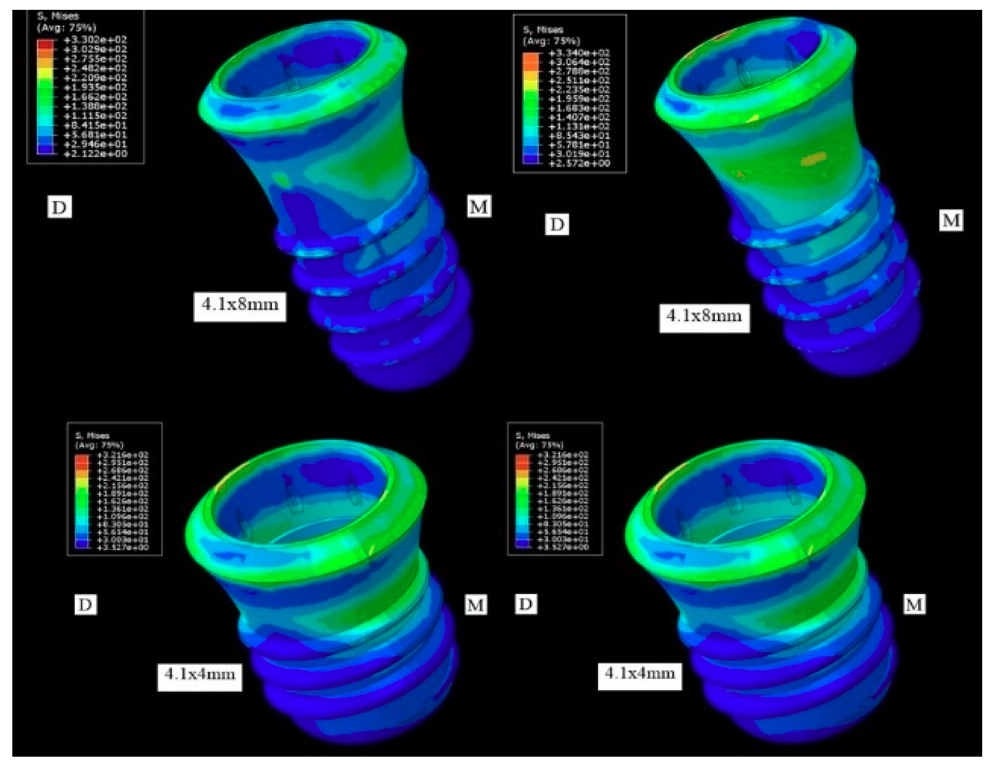
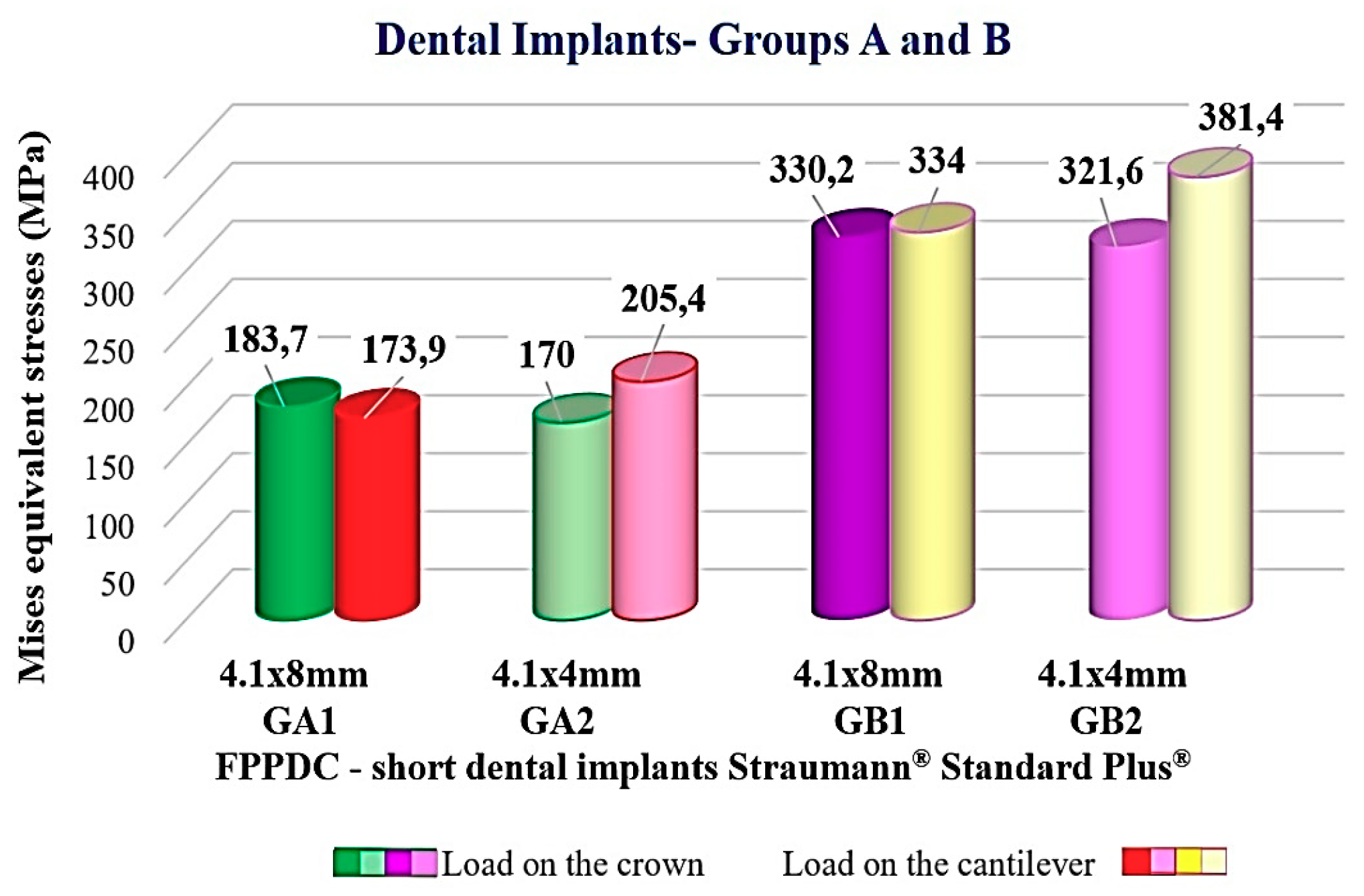
3.1. Distribution of the Tensions in the Implant

In GA1 and GA2, the load applied in the crown it distributed the principal stresses in the cervical third of both implants; in the cantilever area, the tension increased at the cervical third of both implants, also including the middle third the second implant located at the level of the second premolar.
GA2 was greater with respect to GA1, but without significant difference. The distribution of the tensions in GB1 and GB2 was observed in the cervical third of both implants in the cantilever, the principal stresses included the cervical third and middle in both sub-groups. GB2 was greater in relation to GB1 (Table 2; Figure 1, Figure 2 and Figure 3).

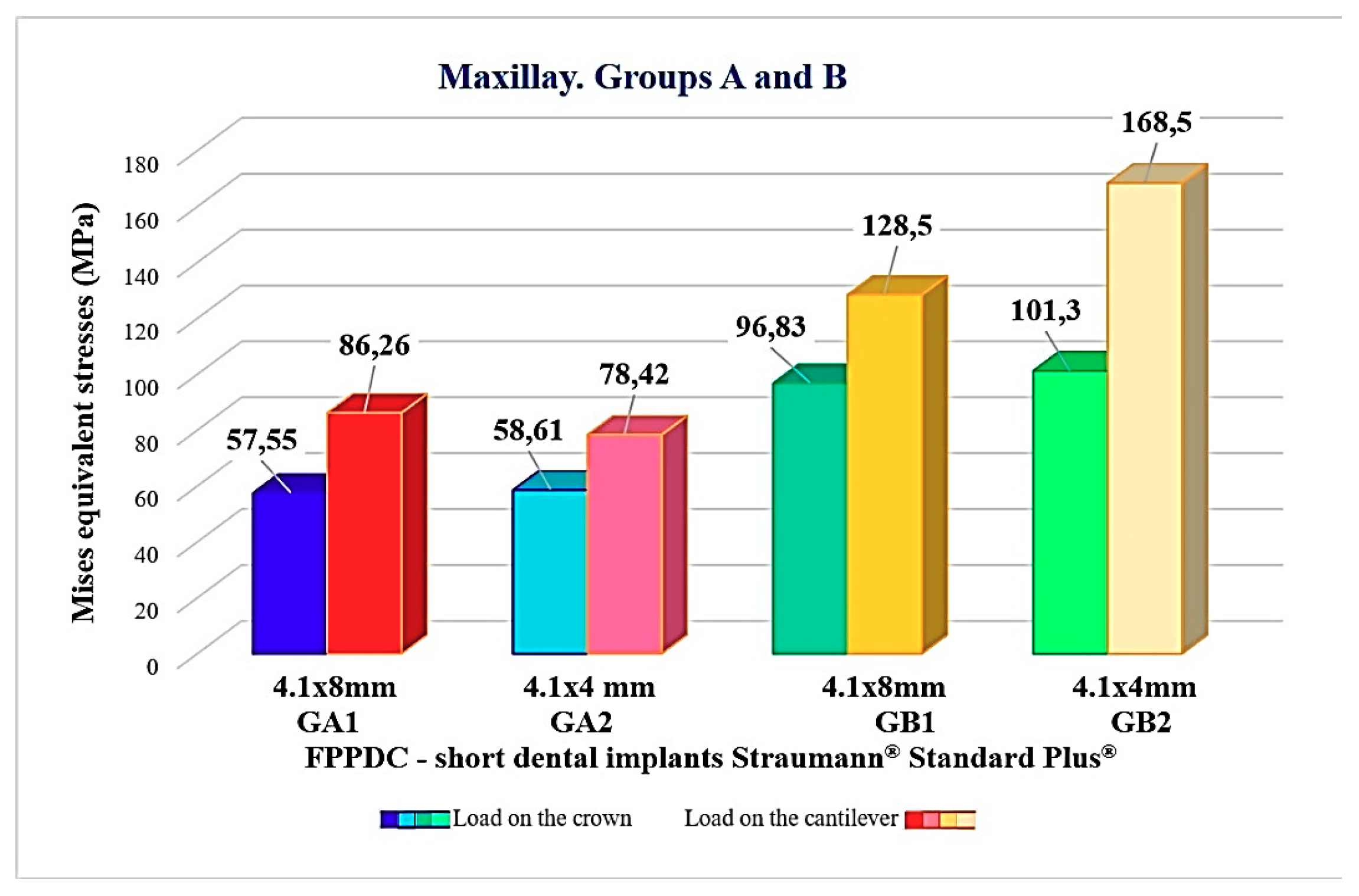
3.2. Distribution of the Tensions in the Solid Model
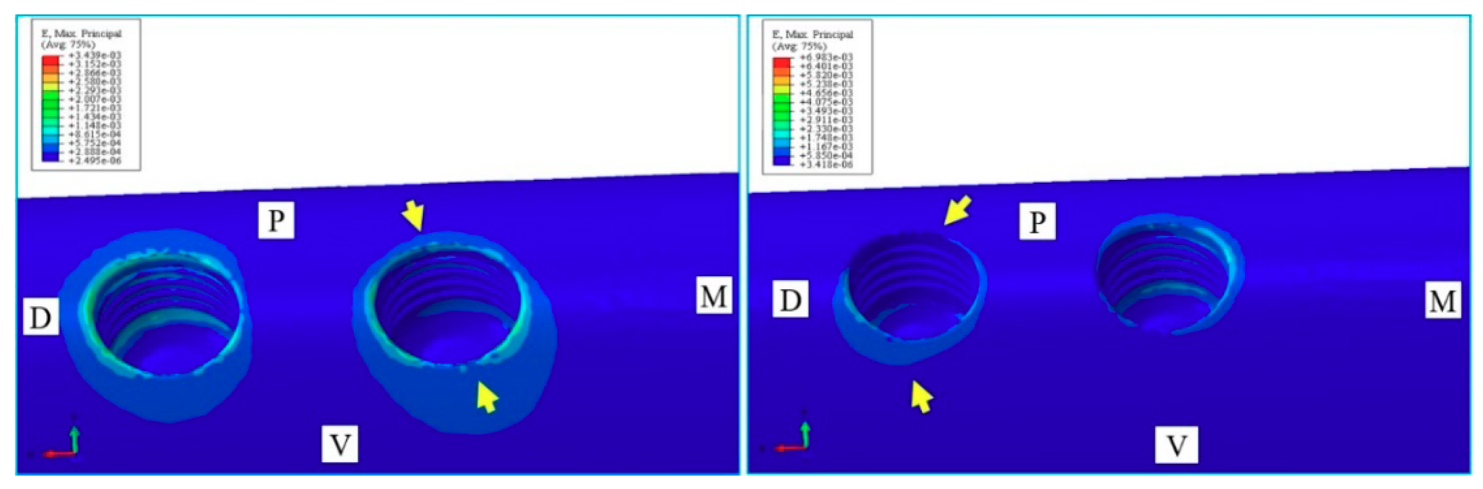
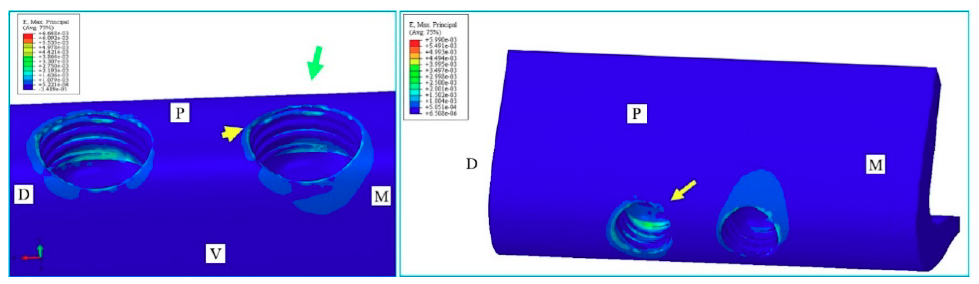
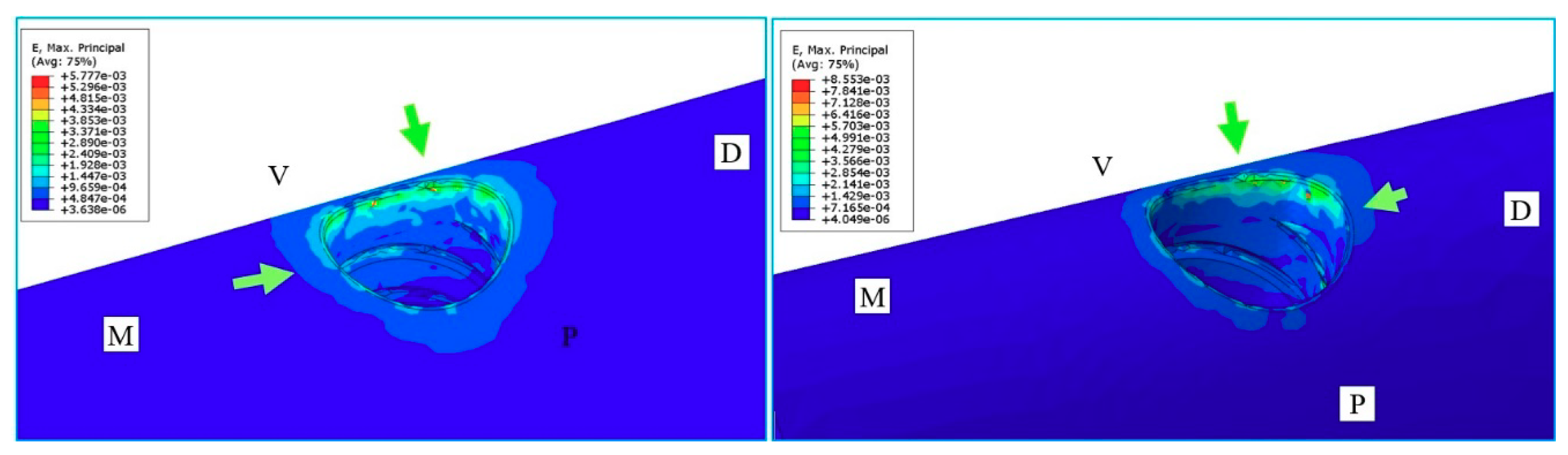
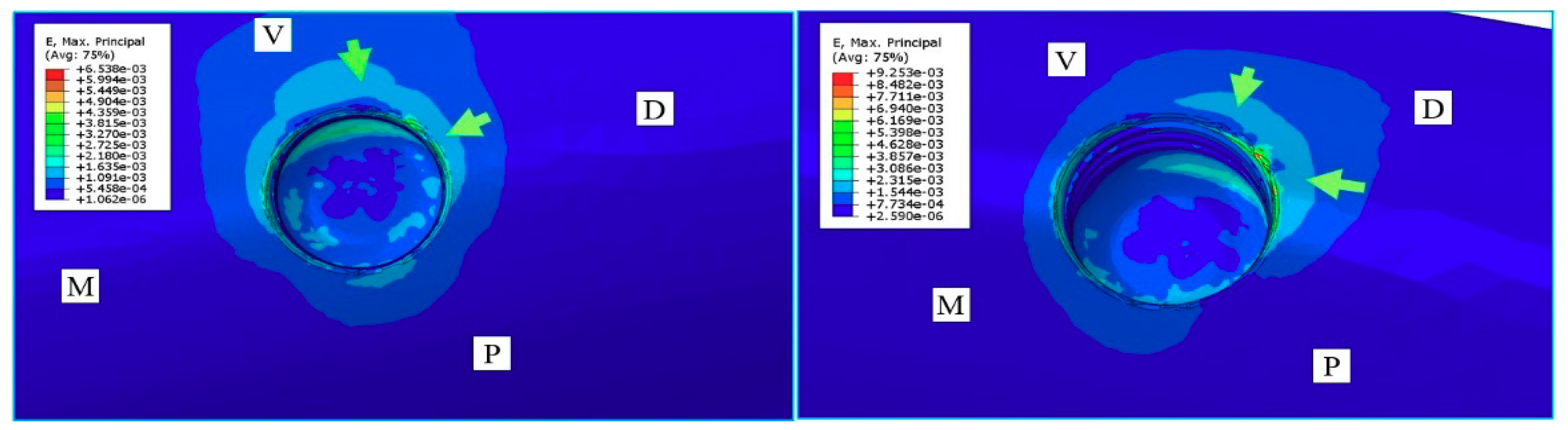
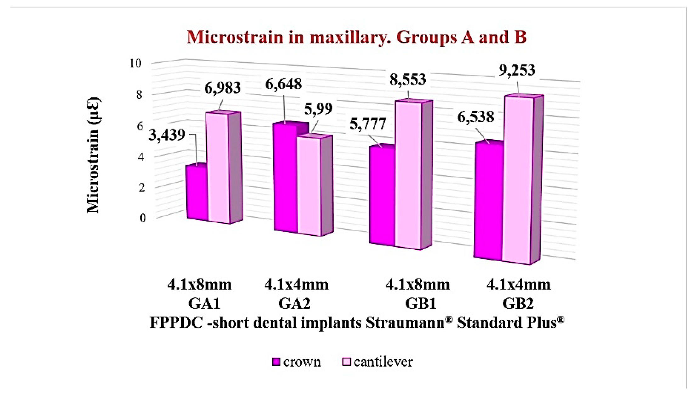
The load in the crown distributed the tensions in the cervical third of GA1 and GA2; in the cantilever, tensions were observed in the cervical third corresponding to the first premolar, and in the cervical and middle third of the second premolar, in both sub-groups. GA1 was greater with respect to GA2, without significant difference among them.
In GB1 and GB2 the distribution of the principal stresses was demonstrated in the cervical third; in the cantilever, increased tensional values were observed in the cervical and middle third, in both sub-groups. GB2 was larger than GB1, with significant differences among them, marking a critical situation on a map for GB2 (Table 3; Figure 4).

3.3. Bone Behavior

The high tensions brought bone micro deformations in a proportional way (higher tensions then more deformation). In GB2 there were higher values with respect to GB1, with significant differences (Table 4 and Figure 5, Figure 6, Figure 7, Figure 8 and Figure 9).

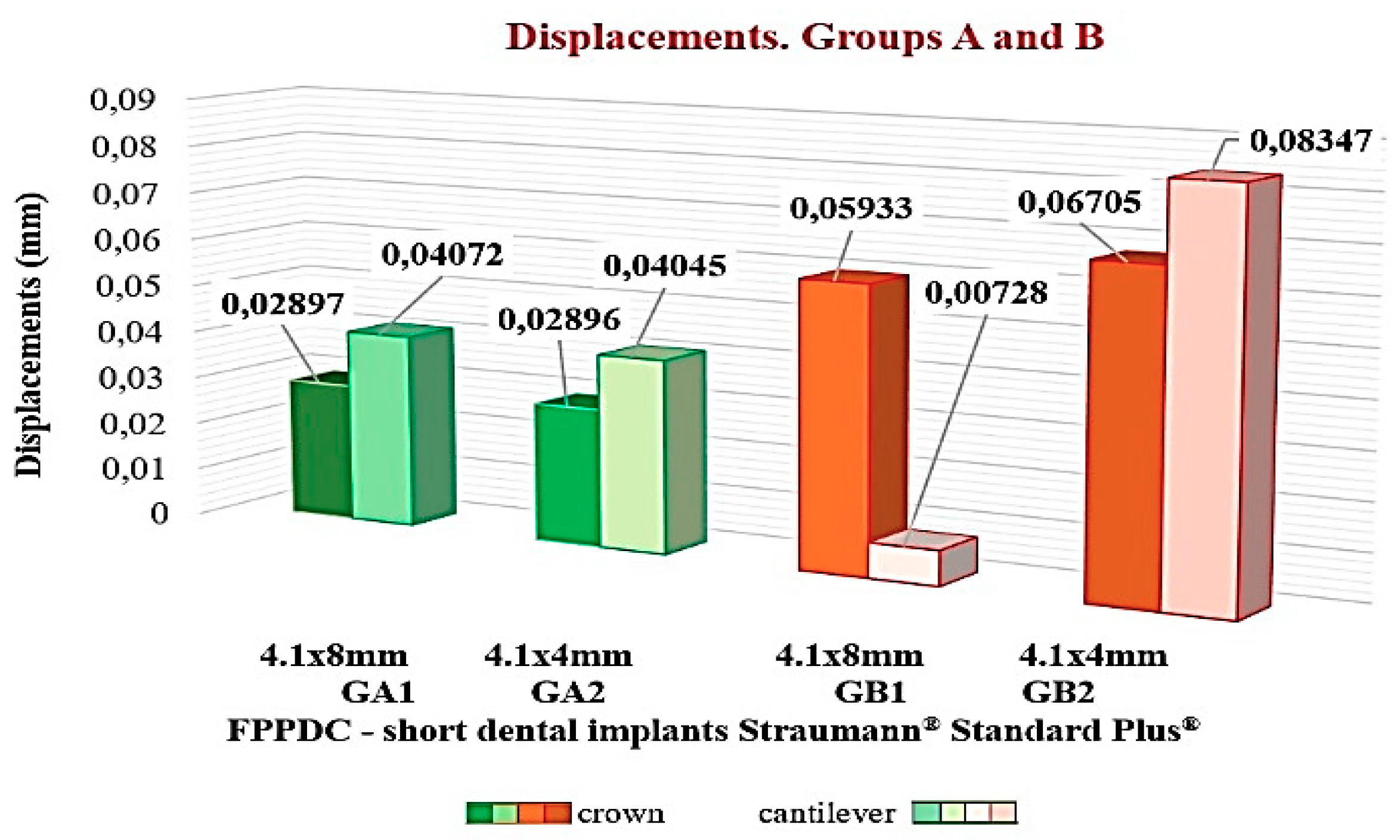
3.4. Prosthesis Behavior

The micro-deformations facilitated the displacement of the joint prosthesis-implant. In GA1 and GA2 it was oriented through the buccal side. In GB1 and GB2 the displacement was in the buccal-distal direction. GB2 was a major that GB1, with significant difference (Table 5; Figure 10).

4. Discussion

The obtained data were described in agreement with a Ceá hypothesis, the error committed in the approach of an exact solution was limited by the error of approach of the obtained solution [27]. The approach error depended crucially on the size and amount of the elements and the equality of other factors that caused this to be smaller, and it was limited to the error of the solution of finite elements. The distribution of short implants in the posterior sector of the maxilla is a challenge when the available bony height is reduced and is next to the floor of the maxillary sinus.
The tension of Von Mises is a physical magnitude of the distortion energy, and is a compound tension that indicates to the average level of tension whose maximum value indicates the possibility of damage occurring. The variables can be manipulated; the software eliminates the variation of the resulting probability of the error of the sample. The initial deformation of the majority of solids is elastic, which implies that the deformation is reversible when stopping applying the tension, and the reason why the solid recovers its initial form.
In the majority of cases, and in agreement with the Hooke’s Law, the relation tension-deformation in the elastic regime is linear, and it expresses σ = E · ε, where σ is the tension expressed in MPa and is the Young’s modulus or modulus of elasticity, and ε is the deformation. If the modulus of elasticity is sprightly, the following formula is obtained whose obtained value indicates that the piece in the study can reconstitute its original form: E = σ/ε. However, when the maximum tensional values surpass the reversible capacity of the material it produces a permanent dimensional change. The deformation formula can be established simply: ε = σ/E. However, the three-dimensional resolution is more complex.
Sotto Maior et al. [28], described the stress concentration in short single implants of 5 mm in diameter by 7 mm in length in 32 partially-edentulous atrophic jaws. They simulated traumatic occlusion and a crown-implant relation of 2:1 or 2.5:1. The crown created high bending stresses which produced a peri-implant bone loss. Bolle et al. [29] used implants 4 mm in diameter and 10 mm in length over the mandibular channel with and without bone augmentation. Additionally, the inserted implants were 4 to 5 mm in length below the maxillary sinus with and without sinus elevation. After one year of load, the short implants obtained similar results compared to implants of conventional lengths (10 mm). They concluded that short implants could be an option to the surgical procedures since the treatment is less invasive, faster, and economical.
Toti et al. [30] inserted short implants in the posterior atrophic zone of partially-edentulous jaws, and their results showed better compared with implants of standard length placed in the augmented bone. Additionally, the short implants presented less crestal bone loss. Tabrizi et al. [31] evaluated the bone loss in 65 short implants in the jaw. There were no significant differences in the marginal bone loss between the three groups analyzed. However, the authors found that increasing the number of short implants reduced the percentages of crestal bone loss given a better force distribution. Gastaldi et al. [32] compared prosthesis on short implants of 5 × 5 mm or of 5 × 10 mm. inserted in atrophic jaws with augmented bone and maxillary bilateral sinus elevation. After three years of load, short implants obtained results similar to standard implants. They concluded that short implants can be a preferable option to the vertical bone augmentation.
Chou et al. [33], compared the stress distribution around the peri-implant bone of narrow implants with standard length (3.5 mm wide by 10.7 mm length) compared with short and wide implants (5 mm diameter by 7 mm length) in the mandible. It was demonstrated that the development of tension in the cervical region is inevitable, with more uniform distributions in the peri-implant tissue in the short and wide implants. Sahrmann et al. [34], compared implants 6 and 10 mm in length through X-rays. Higher mineralization percentages were observed around short implants compared to standard implants. This was related to the capacity of bone adaptation.
Peixoto et al. [35] used digital images to calculate the deformations of the prosthesis supported by splinted short dental implants during an occlusal load of 250 N. It was found that the veneering material did not influence the distribution of the deformation. Esfahrood et al. [36] performed a prospective study comparing the fixed prosthesis with overdentures supported by short implants (<10 mm). The cumulative success in the implant with rough surfaces was higher than in implants with machined surfaces. The survival of short implants in edentulous maxilla was high when the implants were placed under strict clinical protocols. Therefore, the authors consider the short implants as a safe and predictable technique.
On the other hand, Lemos et al. [37] compared short implants (≤8 mm) with standard implants (>8 mm) placed in the posterior regions of the maxilla and the mandible and found that shorter implants >8 mm presented a greater risk of failure. Block et al. [38] analyzed the level of bone deformation when changing the prosthetic design and different occlusal schemes. It was found that the restorations with splinted implants reduced the levels of deformation in the area of the neck of the implants and provide a better deformation distribution under cyclic load. De Souza Batista et al. [39] compared the influence of the pontic designs and the effect of mesial and distal cantilevers in prostheses supported by standard implants (4 × 10 mm). Axial forces of 400 N and of 200 N were applied in an oblique direction. In the group with two implants supporting a distal cantilever, an unfavorable biomechanical behavior with higher stresses was observed.
In the present work, there were no observed differences between GA1 and GA2 implants. The tensions in GB2 were, principally, greater than those of GB1. However, GB2 (4.1 × 4 mm) exerted higher tensions, an unpredictable situation for implants of short height. Ormianer et al. [40] studied the marginal bone loss related to implants of different designs, (different threads, thread direction, and apical design). In the long-term, there was minor bone loss in implants with greater interthread distances, deep apical turns, and narrow cores. Their results favored a single-piece implant design with a “V” thread design. Wolff et al. [14] demonstrated that the effective tensions take place in the bone–implant interface under unidirectional axial load. Four types of implants showed bone loss resulting from pathological tensions >3000 µε. The groups analyzed in the present work were in the rank of pathological overload; this favored the micro deformations and the displacements of the implant/abutment connections.
Villarinho et al. [41] inserted 46 single implants of 4.1 × 6 mm in the posterior areas of the maxilla and the mandible in 20 patients; after 45 ± 9 months the percentages of success were 65.2% and 95%, with more probabilities of implant loss in the jaw than in the maxilla. The crown–implant ratio and the time were significant predictive values for bone loss (p < 0.001). In this research that GA two splinted short implants were observed, which would have the best stress distribution and, therefore, more possibility of permanence in the mouth, and which would give the joint prosthesis-implant greater stability in the long-term.

5. Conclusions

Within the limitations of this FEA:
-
PPFIVD on two extra-short dental implants could be used as a viable option;
-
The tensions are distributed in the cervical third of the implants and to the implant/abutment interface in the form of micro deformations;
-
PPFIVD over single extra short implants of 4.1 × 4 mm possess a high risk or mechanical failure; and
-
The forces generated during the functional load in the posterior area of the maxilla would affect the prosthetic restoration with distal cantilever and would affect the peri-implant bone that surrounds the extra-short dental implants.

Author Contributions

Conceptualization, Enrique Fernández Bodereau.; methodology, Rafael Arcesio Delgado Ruiz, Viviana Yolanda Flores.; software, Viviana Yolanda Flores.; validation, Enrique Fernández Bodereau. and Viviana Yolanda Flores.; formal analysis, Juan Manuel Aragoneses, Viviana Yolanda Flores.; investigation, Viviana Yolanda Flores.; resources, José Luis Calvo Guirado.; data curation, Viviana Yolanda Flores.; writing—original draft preparation, Rafael Arcesio Delgado Ruiz, José Luis Calvo Guirado.; writing—review and editing, Enrique Fernández Bodereau and Viviana Yolanda Flores.; visualization, Juan Manuel AragonesesViviana Yolanda Flores and José Luis Calvo Guirado.; supervision, Enrique Fernández Bodereau.; project administration, Enrique Fernández Bodereau.; funding acquisition, Enrique Fernández Bodereau.”

Funding

This research received no external funding.

Acknowledgments

To the engineer Domínguez A., for his technical collaboration in obtaining the consigned data.

Conflicts of Interest

The authors declare no conflict of interest

References

  1. Brånemark, P.I. Osseointegration and its experimental background. J. Prosthet. Dent. 1983, 50, 399–410. [Google Scholar] [CrossRef]
  2. Cervino, G.; Romeo, U.; Lauritano, F.; Bramanti, E.; Fiorillo, L.; D’Amico, C.; Milone, D.; Laino, L.; Campolongo, F.; Rapisarda, S.; et al. Fem and Von Mises Analysis of OSSTEM® Dental Implant Structural Components: Evaluation of Different Direction Dynamic Loads. Open Dent. J. 2018, 12, 219–229. [Google Scholar] [CrossRef] [PubMed]
  3. Moraschini, V.; Poubel, L.; Ferreira, V.; Barboza Edos, S. Evaluation of survival and success rates of dental implants reported in longitudinal studies with a follow-up period of at least 10 years: A systematic review. Int. J. Oral Maxillofac. Surg. 2015, 44, 377–388. [Google Scholar] [CrossRef] [PubMed]
  4. Ibáñez, J.C.; Tahhan, M.J.; Zamar, J.A. Performance of Double Acid-Etched Surface External Hex Titanium Implants in relation to One-and Two-Stage Surgical Procedures. J. Periodontol. 2003, 74, 1575–1581. [Google Scholar] [CrossRef] [PubMed]
  5. Dawson, J.H.; Hyde, B.; Hurst, M.; Harris, B.T.; Lin, W.S. Polyetherketoneketone (PEKK), a framework material for complete fixed and removable dental prostheses: A clinical report. J. Prosthet. Dent. 2018, 119, 867–872. [Google Scholar] [CrossRef] [PubMed]
  6. Najeeb, S.; Zafar, M.S.; Khurshid, Z.; Siddiqui, F. Applications of polyetheretherketone (PEEK) in oral implantology and prosthodontics. J. Prosthodont. Res. 2016, 60, 12–19. [Google Scholar] [CrossRef] [PubMed]
  7. Thoma, S.D.; Cha, J.K.; Jung, U.W. Treatment concepts for the posterior maxilla and mandible: Short implants vs long implants in augmented bone. J. Periodont. Implant Sci. 2017, 47, 2–12. [Google Scholar] [CrossRef] [PubMed]
  8. Raviv, E.; Turcotte, A.; Harel Raviv, M. Short dental implants in reduced alveolar bone height. Quintessence Int. 2010, 41, 505–509. [Google Scholar]
  9. Felice, P.; Checchi, L.; Barausse, C.; Pistilli, R.; Sammartino, G.; Masi, I.; Ippolito, D.R.; Esposito, M. Posterior jaws rehabilitated with partial prostheses supported by 4.0 × 4.0 mm or by longer implants: One-year post-loading results from a multicenter randomized controlled trial. Eur. J. Oral Implantol. 2016, 9, 35–45. [Google Scholar]
  10. Blanes, R.J.; Bernard, J.P.; Blanes, Z.M.; Belser, U.C. A 10-year prospective study of ITI dental implants placed in the posterior region. II: Influence of the crown-to-implant ratio and different prosthetic treatment modalities on crestal bone loss. Clin. Oral Implants Res. 2007, 18, 707–714. [Google Scholar] [CrossRef]
  11. Urdaneta, R.A.; Rodriguez, S.; McNeil, D.C.; Weed, M.; Chuang, S.K. The effect of increased Crown-to-Implant Ratio on Single Tooth Locking Taper Implants. Int. J. Oral Maxillofac. Implants 2010, 25, 709–743. [Google Scholar]
  12. Zurdo, J.; Romao, C.; Wennstrom, J.L. Survival and complication rates of implant-supported fixed partial dentures with cantilevers: A systematic review. Clin. Oral Implants Res. 2009, 20, 59–66. [Google Scholar] [CrossRef] [PubMed]
  13. Salvi, G.E.; Brägger, U. Mechanical and technical risks in implant therapy. Int. J. Oral Maxillofac. Implants 2009, 24, 69–85. [Google Scholar] [PubMed]
  14. Wolff, J.; Narra, N.; Antalainen, A.K.; Valášek, J.; Kaiser, J.; Sándor, G.K.; Marcián, P. Finite element analysis of bone loss around failing implants. Mater. Des. 2014, 61, 177–184. [Google Scholar] [CrossRef]
  15. Cicciù, M.; Cervino, G.; Milone, D.; Risitano, G. FEM Investigation of the Stress Distribution over Mandibular Bone Due to Screwed Overdenture Positioned on Dental Implants. Materials 2018, 11, 1512. [Google Scholar]
  16. Lauritano, F.; Runci, M.; Cervino, G.; Fiorillo, L.; Bramanti, E.; Cicciù, M. Three-dimensional evaluation of different prosthesis retention systems using finite element analysis and the Von Mises stress test. Minerva Stomatol. 2016, 65, 353–367. [Google Scholar] [PubMed]
  17. Sahin, S.; Cehreli, M.C.; Yalcin, E. The influence of functional forces on the biomechanics of implant-supported prosthesis—A review. J. Dent. 2002, 30, 271–282. [Google Scholar] [CrossRef]
  18. Mellal, A.; Wiskott, H.W.; Botsis, J.; Scherer, S.S.; Belser, U.C. Stimulating effect of implant loading on the surrounding bone. Comparison of three numerical models and validation by in vivo data. Clin. Oral Implants Res. 2004, 15, 239–248. [Google Scholar] [CrossRef] [PubMed]
  19. Geng, J.P.; Tan, K.B.C.; Liu, G.R. Application of finite element analysis in implant dentistry: A review of the literature. J. Prosthet. Dent. 2001, 85, 585–598. [Google Scholar] [CrossRef]
  20. Sohn, B.S.; Heo, S.J.; Koak, J.Y.; Kim, S.K.; Lee, S.Y. Strain of implants depending on occlusion types in mandibular implant-supported fixed prostheses. J. Adv. Prosthodont. 2011, 3, 1–9. [Google Scholar] [CrossRef] [PubMed]
  21. Fernández Bodereau, E., Jr.; Fernández Bodereaum, E. Prótesis a Puente. Selección y valoración de places. In Prótesis Fija e Implantes. Práctica Clínica; Ed Avances Médico-Dentales SL: Madrid, Spain, 1996; pp. 295–320. [Google Scholar]
  22. Fazi, G.; Tellini, S.; Vangi, D.; Branchi, R. Three-dimensional finite element analysis of different implant configuration for mandibular fixed prosthesis. Int. J. Oral Maxillofac. Implants 2011, 26, 752–759. [Google Scholar] [PubMed]
  23. Turner, M.J. Stiffness and Deflection Analysis of Complex Structures. J. Aeronaut. Sci. 1956, 23, 805–823. [Google Scholar] [CrossRef]
  24. Okumura, N.; Stegaroiu, R.; Kitamura, E.; Kurokawa, K.; Nomura, S. Influence of maxillary cortical bone thickness, implant design and implant diameter on stress around implants: A three-dimensional finite element analysis. J. Prosthodont. Res. 2010, 54, 133–142. [Google Scholar] [CrossRef] [PubMed]
  25. De Almeida, E.O.; Rocha, E.P.; Freitas, A.C., Jr.; Freitas, M.M., Jr. Finite Element Stress Analysis of Edentulous Mandibles with Different Bone Types Supporting Multiple-Implant Superstructures. Int. J. Oral Maxillofac. Implants 2010, 25, 1108–1114. [Google Scholar] [PubMed]
  26. Romeo, E.; Tomasi, C.; Finini, I.; Casentini, P.; Lops, D. Implant-supported fixed cantilever prosthesis in partially edentulous jaws: A cohort prospective study. Clin. Oral Implants Res. 2009, 20, 1278–1285. [Google Scholar] [CrossRef] [PubMed]
  27. Céa, J. Approximation Variationnelle des Problèmes aux Limites. Ann. Inst. Fourier. 1964, 14, 345–444. [Google Scholar] [CrossRef]
  28. Sotto Maior, B.S.; Senna, P.M.; da Silva, W.J.; Rocha, E.P.; Del Bel Cury, A.A. Influence of crown-to-implant ratio. Retention system, restorative material, and occlusal loading on stress concentrations in single short implants. Int. J. Oral Maxillofac. Implants 2012, 27, 13–18. [Google Scholar]
  29. Bolle, C.; Felice, P.; Barausse, C.; Pistilli, V.; Trullenque-Eriksson, A.; Esposito, M. 4 mm long vs longer implants in augmented bone in posterior atrophic jaws: 1-Year post-loading results from a multicentre randomized controlled trial. Eur. J. Oral Implantol. 2018, 11, 31–47. [Google Scholar]
  30. Toti, P.; Marchionni, S.; Menchini-Fabris, G.B.; Marconcini, S.; Covani, U.; Barone, A. Surgical techniques used in the rehabilitation of partially edentulous patients with atrophic posterior mandible: A systematic review and meta-analysis of randomized controlled clinical trials. J. Craniomaxillofac. Surg. 2017, 45, 1236–1245. [Google Scholar] [CrossRef]
  31. Tabrizi, R.; Arabion, H.; Aliabadi, E.; Hasanzadeh, F. Does increasing the number of short implants reduce marginal bone loss in the posterior mandible? A prospective study. Br. J. Oral Maxillofac. Surg. 2016, 54, 731–735. [Google Scholar] [CrossRef]
  32. Gastaldi, G.; Felice, P.; Pistilli, V.; Barausse, C.; Ippolito, D.R.; Esposito, M. Posterior atrophic jaws rehabilitated with prostheses supported by 5 × 5 mm implants with a nanostructured calcium-incorporated titanium surface o by longer implants in augmented bone. 3-Year results from a randomized controlled trial. Eur. J. Oral Implantol. 2018, 11, 49–61. [Google Scholar] [PubMed]
  33. Chou, H.Y.; Müftü, S.; Bozkava, D. Combined effects of implants insertion depth and alveolar bone quality on peri-implant bone strain induced by a wide-diameter, short implant, and a narrow-diameter, long implant. J. Prosthet. Dent. 2010, 104, 293–300. [Google Scholar] [CrossRef]
  34. Sahrmann, P.; Schoen, P.; Naenni, N.; Jung, R.; Attin, T.; Schmidlin, P.R. Peri-implant Bone Density around Implants of Different Length: A 3-year Follow-up of Randomized Clinical Trial. J. Clin. Periodontol. 2017, 44, 762–768. [Google Scholar] [CrossRef] [PubMed]
  35. Peixoto, R.F.; Macedo, A.P.; Martinelli, J.; Faria, A.C.; Tiossi, R.; Ribeiro, R.F.; de Mattos, M.D. A Digital Image Correlation Analysis of Strain Generated by 3-Unit Implant-Supported Fixed Dental Prosthesis: An In Vitro Study. Implant Dent. 2017, 26, 567–573. [Google Scholar] [CrossRef] [PubMed]
  36. Esfahrood, Z.R.; Ahmadi, L.; Karami, E.; Asghari, S. Short dental implants in the posterior maxilla: A review of the literature. J. Korean Assoc. Oral Maxillofac. Surg. 2017, 43, 70–76. [Google Scholar] [CrossRef] [PubMed]
  37. Lemos, C.A.; Ferros-Alves, M.L.; Okamoto, R.; Mendonca, M.R.; Pellizzer, E.P. Short dental implants vs standard dental implants placed in the posterior jaw: A systematic review and meta-analysis. J. Dent. 2016, 47, 8–17. [Google Scholar] [CrossRef] [PubMed]
  38. Block, J.; Matalon, S.; Tanase, G.; Ormianer, Z. Effect of Restorative Configurations and Occlusal Schemes on Strain Levels on Bone Surrounding Implants. Implant Dent. 2017, 26, 574–580. [Google Scholar] [CrossRef]
  39. De Souza Batista, V.E.; Verri, F.R.; Almeida, D.A.; Santiago Junior, J.F.; Lemos, C.A.; Pellizzer, E.P. Finite element analysis of implant-supported prosthesis with pontic and cantilever in the posterior maxilla. Comput. Methods Biomech. Biomed. Eng. 2017, 20, 663–670. [Google Scholar] [CrossRef]
  40. Ormianer, Z.; Matalon, S.; Block, J.; Kohen, J. Dental Implant Thread Design and the Consequences on Long-Term Marginal Bone Loss. Implant Dent. 2016, 25, 471–477. [Google Scholar] [CrossRef]
  41. Villarinho, E.A.; Triches, D.F.; Alonso, F.R.; Mezzomo, L.A.M.; Teixeira, E.R.; Shinkai, R.S.A. Risk factors for single crowns supported by shorts (6-mm) implants in the posterior region: A prospective clinical and radiographic study. Clin. Implant Dent. Relat. Res. 2017, 19, 671–680. [Google Scholar] [CrossRef]
Figure 1. Distribution of the main stresses in short implants. On the left of the figure, the load on the crown of the implant-supported fixed partial prosthesis on two implants of 4.1 × 8 mm (top) and 4.1 × 4 mm (below) observed. To the right of the figure, the load in the cantilever is observed. A. Implant located at the level of the first upper premolar and B at the level of the second upper premolar. Cervical tensions are observed in both A and B.
Symmetry 10 00762 g001
Figure 2. Distribution of the main tensions in the short implants located at the level of the first upper premolar. On the left of the figure, the load on the crown of the implant-supported fixed partial prosthesis is observed on an implant of 4.1 × 8 mm (on top) and 4.1 × 4 mm (below). To the right of the figure, the load in the cantilever is observed. Tensions are observed in the cervical and middle third.
Symmetry 10 00762 g002
Figure 3. Distribution principal stresses in implants. Fixed partial prosthesis with distal cantilever, supported by ultrashort implants -FPPDC-.
Symmetry 10 00762 g003
Figure 4. Distribution principal stresses in maxillary. Fixed implant-supported partial prosthesis with distal cantilever -FPPDC-.
Symmetry 10 00762 g004
Figure 5. Microdeformations in the maxillary. Load on the crown (left) and the cantilever (right) of PPDC supported by two ultrashort implants of 4.1 × 8 mm. Arrows indicate microstrain in the bone crest.
Symmetry 10 00762 g005
Figure 6. Microstrain in the maxillary. Load on the crown (left) and the cantilever (right) of the PPFIVD supported by two ultrashort implants of 4.1 × 4 mm. Arrows indicate microstrain in the bone crest.
Symmetry 10 00762 g006
Figure 7. Microdeformations in the maxilla. Load on the crown (left) and on the cantilever (right) of the PPFIVD supported by an ultrashort implant of 4.1 × 8 mm. Arrows indicate microstrain in the bone crest.
Symmetry 10 00762 g007
Figure 8. Microdeformations in the maxilla. Load on the crown (left) and the cantilever (right) of the PPFIVD supported by an ultrashort 4.1 × 4mm. Arrows indicate microstrain in the bone crest.
Symmetry 10 00762 g008
Figure 9. Microstrain in maxillary. Fixed partial prosthesis with distal cantilever, supported by ultrashort implants -FPPDC-.
Symmetry 10 00762 g009
Figure 10. Displacements of the fixed partial prosthesis with distal cantilever, supported by ultrashort implants -FPPDC-.
Symmetry 10 00762 g010
Table 1. Numeric detail geometric patterns made for this investigation.
ModelsAmount of ElementsNumber of NodesTypes of ElementsBone Height
(mm)
Implants Dimensions
(mm)
Two implants321,06665,826Tetrahedron94.1 × 8
Two implants424,67285,442Tetrahedron54.1 × 4
An implant199,44340,776Tetrahedron94.1 × 8
An implant264,07653,261Tetrahedron54.1 × 4
Table 2. Distribution of the principal stresses in ultrashort implants.
ModelsCrown (MPa)Cantilever
(MPa)
Load
(N)
Implant Dimensions
(mm)
A
Two implants
183.7173.91004.1 × 8
170205.41004.1 × 4
B
An implant
330.23341004.1 × 8
321.6381.41004.1 × 4
Table 3. Distribution of the principal stresses in the maxillary.
ModelsCrown (MPa)Cantilever
(MPa)
Load
(N)
Implant Dimensions
(mm)
A
Two implants
57.5586.261004.1 × 8
58.6178.421004.1 × 4
B
An implant
96.83128.51004.1 × 8
101.3168.51004.1 × 4
Table 4. Distribution of the microstrain in the solid model. Fixed partial prosthesis with distal cantilever, supported by ultrashort implants.
ModelsCrown (Maximum Tensile)
με
Cantilever
(Maximum Tensile)
με
Load
(N)
Implants Dimensions
(mm)
A
Two implants
3.4396.9831004.1 × 8
6.6485.9901004.1 × 4
B
An implant
5.7778.5531004.1 × 8
6.5389.2531004.1 × 4
Table 5. Displacements of the fixed partial prosthesis with distal cantilever supported by ultrashort implants.
ModelsDisplacement Crown
(mm)
Displacement Cantilever
(mm)
Load
(N)
Implant Dimensions
(mm)
A
Two short implants
0.028970.040721004.1 × 8
0.028960.040451004.1 × 4
B
A short implant
0.059330.007281004.1 × 8
0.067050.083471004.1 × 4

